- Table of Contents
- Related Documents
-
| Title | Size | Download |
|---|---|---|
| 02-ER G3 Routers Inter-VLAN Access Control Configuration Examples | 396.65 KB |
ERG3 Routers
Inter-VLAN Access Control Configuration Examples
|
Copyright © 2024 New H3C Technologies Co., Ltd. All rights reserved. No part of this manual may be reproduced or transmitted in any form or by any means without prior written consent of New H3C Technologies Co., Ltd. Except for the trademarks of New H3C Technologies Co., Ltd., any trademarks that may be mentioned in this document are the property of their respective owners. The information in this document is subject to change without notice. |
Introduction
The following information provides an example of denying inter-VLAN accesses.
Prerequisites
This document is not restricted to specific software or hardware versions. Procedures and information in the examples might be slightly different depending on the software or hardware version of the device.
The configuration examples were created and verified in a lab environment, and all the devices were started with the factory default configuration. When you are working on a live network, make sure you understand the potential impact of every command on your network.
The following information is provided based on the assumption that you have basic knowledge of ACL and QoS.
Example: Denying inter-VLAN accesses
Network configuration
As shown in Figure 1, the device acts as the egress router for the enterprise network. Create two VLANs, VLAN 2 and VLAN 3, on the device. The subnet for VLAN 2 is 192.168.2.0/24, and the subnet for VLAN 3 is 192.168.3.0/24. Configure the device to meet the following requirements:
· Allow users in VLAN 2 and VLAN 3 to access the Internet.
· Denying accesses between VLAN 2 and VLAN 3.

Software versions used
This configuration example was created and verified on Release 0136 of the ER3200G3 router.
Procedures
Configuring WAN1 to connect to the Internet
1. On the Web interface of the device, select Network Settings > External Networks.
2. Click the WAN Settings tab.
3. Click the Edit icon in the Actions column for WAN1.
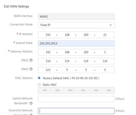
4. In the Connection Mode field, select Fixed IP.
5. In the IP Address field, enter 192.168.200.21.
6. In the Subnet Mask field, enter 255.255.255.0.
7. In the Gateway Address field, enter 192.168.200.1.
8. Use the default settings for the other parameters, and then click Apply.
Figure 2 Editing WAN settings
Configuring VLAN 2 and the interface IP address
# On the router, configure VLAN 2 and configure its interface IP address as 192.168.2.1/24.
1. On the Web interface of the device, select Network Settings > LANs. Click the VLAN Settings tab.
2. Click Add.
3. In the VLAN ID field, enter 2.
4. In the IP Address field, enter 192.168.2.1.
5. In the Subnet Mask field, enter 255.255.255.0.
6. Select Enable DHCP.
7. Use the default settings for the other parameters, and then click Apply.
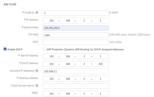
Figure 3 Configuring VLAN 2

Configuring VLAN 3 and the interface IP address
# On the router, configure VLAN 3 and configure its interface IP address as 192.168.3.1/24.
1. On the Web interface of the device, select Network Settings > LANs. Click the VLAN Settings tab.
2. Click Add.
3. In the VLAN ID field, enter 3.
4. In the IP Address field, enter 192.168.3.1.
5. In the Subnet Mask field, enter 255.255.255.0.
6. Select Enable DHCP.
7. Use the default settings for the other parameters, and then click Apply.
Figure 4 Configuring VLAN 3
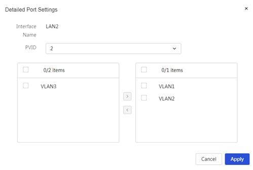
Assigning interface LAN2 to VLAN 2
1. On the Web interface of the device, select Network Settings > LANs.
2. Click the Edit icon in the Actions column for interface LAN2.
3. In the PVID field, select 2.
4. Click Apply.
Figure 5 Assigning interface LAN2 to VLAN 2
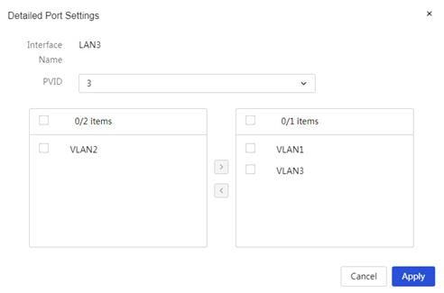
Assigning interface LAN3 to VLAN 3
1. On the Web interface of the device, select Network Settings > LANs.
2. Click the Edit icon in the Actions column for interface LAN3.
3. In the PVID field, select 3.
4. Click Apply.
Figure 6 Assigning interface LAN3 to VLAN 3
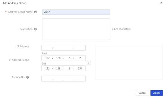
Configuring address groups
# Set the subnet for VLAN 2 (192.168.2.1/24) as address group vlan2.
1. On the Web interface of the device, select Network Settings > Address Groups page.
2. Click Add.
3. In the Address Group Name field, enter vlan2.
4. In the IP Address Range field, enter start IP address 192.168.2.2 and end IP address 192.168.2.254.
5. Click àà.
6. Click Apply.
Figure 7 Configuring address group vlan2
# Set the subnet for VLAN 3 (192.168.3.1/24) as address group vlan3.
1. On the Web interface of the device, select Network Settings > Address Groups page.
2. Click Add.
3. In the Address Group Name field, enter vlan3.
4. In the IP Address Range field, enter start IP address 192.168.3.2 and end IP address 192.168.3.254.
5. Click àà.
6. Click Apply.
Figure 8 Configuring address group vlan3

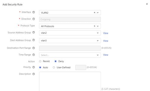
Denying accesses between VLAN 2 and VLAN 3
# Enable the firewall feature and deny accesses between VLAN 2 and VLAN 3.
1. On the Web interface of the device, select Security > Firewall.
2. Select the Enable Firewall option.
3. Use the default action of Permit in the Default Filtering Rule field.
4. Add a security rule to deny accesses between VLAN 2 and VLAN 3.
a. Click Add to add a security rule.
b. In the Interface field, select VLAN2.
c. In the Protocol Type field, select All Protocols.
d. In the Source Address Group field, select vlan2.
e. In the Dest Address Group field, select vlan3.
f. In the Action field, select Deny.
g. In the Priority field, select Auto.
h. Use the default settings for the other parameters, and then click Apply.
Figure 9 Denying accesses between VLAN 2 and VLAN 3
Verifying the configuration
# Users in VLAN 2 cannot access users in VLAN 3.
C:\Users\vlan2a>ping –S 192.168.2.2 192.168.3.2
Ping 192.168.3.2 from 192.168.2.2 with 32 Bytes of data:
Request timed out.
Request timed out.
Request timed out.
Request timed out.
