- Table of Contents
-
- 09-L2TP Configuration
- 01-ER G3 Routers L2TP VPN Configuration Examples
- 02-Set Up L2TP VPN Connection by Using Custom iNode Client for Windows
- 03-MER Routers L2TP (LAC-Auto-Initiated Mode) Configuration Examples
- 04-MER Routers L2TP VPN Configuration Examples
- 05-MSR Routers LAC-Auto-Initiated L2TP Tunnel Configuration Examples
- 06-MSR Routers L2TP VPN+RADIUS Server Configuration Examples
- 07-MSR Routers L2TP VPN Configuration Examples (CLI)
- 08-MSR Routers L2TP VPN Configuration Examples
- 09-Setting Up L2TP VPN in macOS
- Related Documents
-
| Title | Size | Download |
|---|---|---|
| 07-MSR Routers L2TP VPN Configuration Examples (CLI) | 375.45 KB |
MSR Routers
L2TP VPN Configuration Examples (CLI)
Copyright © 2024 New H3C Technologies Co., Ltd. All rights reserved.
No part of this manual may be reproduced or transmitted in any form or by any means without prior written consent of New H3C Technologies Co., Ltd.
Except for the trademarks of New H3C Technologies Co., Ltd., any trademarks that may be mentioned in this document are the property of their respective owners.
The information in this document is subject to change without notice.
Contents
Introduction
This document provides examples for configuring L2TP VPNs on routers.
Prerequisites
This document is not restricted to specific software or hardware versions. Procedures and information in the examples might be slightly different depending on the software or hardware version of the device.
The configuration examples were created and verified in a lab environment, and all the devices were started with the factory default configuration. When you are working on a live network, make sure you understand the potential impact of every command on your network.
The following information is provided based on the assumption that you have basic knowledge of L2TP VPN.
Software versions used
This configuration example was created and verified on Version 7.1.064 Feature 6749L15 of the MSR3610 router.
Configuration example
Network configuration
As shown in Figure 1, a company requires external office staff to access the internal network through L2TP VPN.

Analysis
1. Configure an address pool for allocating IP addresses to hosts.
2. Host accesses the company's internal server by establishing an L2TP VPN.
Procedures
Configuring the router
Configuring IP addresses for interfaces
# Enter the view of interface GigabitEthernet 0/1 and configure its IP address as 20.1.1.1/24.
<Router> system-view
[Router] interface gigabitethernet 0/1
[Router-GigabitEthernet0/1] ip address 20.1.1.1 24
[Router-GigabitEthernet0/1] quit
# Enter the view of interface GigabitEthernet 0/2 and configure its IP address as 192.168.2.1/24.
[Router] interface gigabitethernet 0/2
[Router-GigabitEthernet0/2] ip address 192.168.2.1 24
[Router-GigabitEthernet0/2] quit
Configuring the default route
# Configure the default route to the Internet.
[Router] ip route-static 0.0.0.0 0 20.1.1.1
Configuring address pools
# Enable DHCP.
[Router] dhcp enable
# Create address pool pool1 for address allocation.
[Router] ip pool pool1 192.168.1.2 192.168.1.100
[Router] ip pool pool1 gateway 192.168.1.1
Configuring ISP domains
# Create ISP domain L2TP, and enter its view.
[Router] domain l2tp
[Router-isp-l2tp] authentication ppp radius-scheme l2tp
[Router-isp-l2tp] accounting ppp radius-scheme l2tp
[Router-isp-l2tp] authorization ppp radius-scheme l2tp
[Router-isp-l2tp] quit
Configuring users
# Create a local user named vpdnuser.
[Router] local-user vpdnuser class network
# Configure the password as user1234.
[Router-luser-network-vpdnuser] password cipher user1234
# Specify the service type as PPP.
[Router-luser-network-vpdnuser] service-type ppp
[Router-luser-network-vpdnuser] quit
Configuring a virtual template
# Create VT interface 1.
[Router] int Virtual-Template 1
# Configure the interface to authenticate the endpoint by using CHAP certification and ISP domain system.
[Router-Virtual-Template1] ppp authentication-mode chap domain system
# Configure Virtual-Template 1 to use address pool pool1 for allocating IP addresses to hosts.
[Router-Virtual-Template1] remote address pool pool1
# Configure the IP address of Virtual-Template 1 as 192.168.1.2/24.
[Router-Virtual-Template1] ip address 192.168.1.1 24
[Router-Virtual-Template1] quit
Configuring L2TP
# Enable L2TP.
[Router] l2tp enable
# Create L2TP group 1 and specify the L2TP group mode as LNS.
[Router] l2tp-group 1 mode lns
# Specify interface Virtual-Template 1 for setting up an L2TP tunnel.
[Router-l2tp1] allow l2tp virtual-template 1
# Disable tunnel authentication.
[Router-l2tp1] undo tunnel authentication
[Router-l2tp1] quit
Configuring the L2TP client
|
|
NOTE: On Host, configure the L2TP client. In this example, the PC is installed with Windows 7. |
# Log in to Host. Click the Network ![]() icon
in the lower right corner of the PC, and click Open
Network and Sharing Center.
icon
in the lower right corner of the PC, and click Open
Network and Sharing Center.
Figure 2 Opening the network and sharing center window
![]()
# Click Set up a new connection or network to create an L2TP client.
Figure 3 Setting up a new connection or network

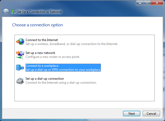
# In the Set up a Connection or Network window, select Connect to a workplace, and then click Next.
Figure 4 Connecting to the workspace
# Select Use my Internet connection (VPN), and then select I’ll set up an Internet connection later. Then, you can configure the Internet address for the connection.
Figure 5 Using my Internet connection (VPN)

# In the Internet address field, enter the IP address to be connected, 20.1.1.1 in this example. In the Destination name field, enter the name of the L2TP client connection, l2tp in this example. Then, click Next.
Figure 6 Entering the Internet address you want to connect to

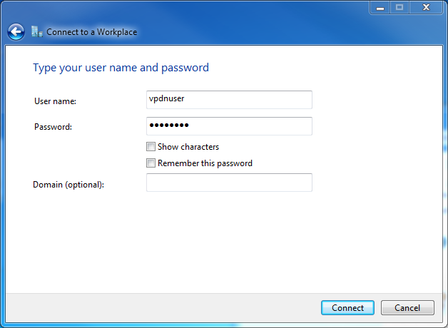
# In the User name and Password fields, enter the username and password set on the L2TP server, vpdnuser and user1234 in this example. Click Create.
Figure 7 Entering the username and password
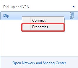
# Click the Network![]() icon in the lower right corner of the desktop. Right-click the L2TP client name
(for example, l2tp), and select Properties.
icon in the lower right corner of the desktop. Right-click the L2TP client name
(for example, l2tp), and select Properties.
Figure 8 L2TP client properties
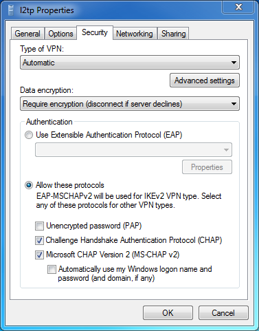
# In the Properties dialog box that opens, click the Security tab. On this tab, select Layer 2 Tunneling Protocol with IPsec (L2TP/IPsec) from the Type of VPN list, select Optional encryption (connect even if no encryption) from the Data encryption list, and then click OK.
Figure 9 Configuring security properties
# Open the dialup terminal for L2TP, and enter username vpdnuser and password user1234 in the Connect dialog box that opens. Then, click Connect.
Figure 10 L2TP connection

Verifying the configuration
After successfully establishing the L2TP connection, Host can ping the internal network server (RADIUS server).
ping 192.168.2.2
Pinging 192.168.2.2 with 32 bytes of data:
Reply from 192.168.2.2: Bytes=32 time=26ms TTL=126
Reply from 192.168.2.2: Bytes=32 time<1ms TTL=128
Reply from 192.168.2.2: Bytes=32 time<1ms TTL=128
Reply from 192.168.2.2: Bytes=32 time<1ms TTL=128
Ping statistics for 192.168.2.2:
Packets Sent = 4, Received = 4, Lost = 0 (0% loss),
Approximate round trip time in milli-seconds:
Minimum = 0ms, Maximum = 26ms, Average = 6ms
Configuration files
#
sysname Router
#
dhcp enable
#
ip pool pool1 192.168.1.2 192.168.1.100
ip pool pool1 gateway 192.168.1.1
#
interface Virtual-Template1
ppp authentication-mode chap domain system
remote address pool pool1
ip address 192.168.1.1 255.255.255.0
#
interface GigabitEthernet0/1
ip address 20.1.1.1 255.255.255.0
#
interface GigabitEthernet0/2
ip address 192.168.2.1 255.255.255.0
#
ip route-static 0.0.0.0 0 20.1.1.1
#
local-user vpdnuser class network
service-type ppp
authorization-attribute user-role network-operator
#
l2tp-group 1 mode lns
allow l2tp virtual-template 1
undo tunnel authentication
#
l2tp enable
