- Table of Contents
-
- 09-L2TP Configuration
- 01-ER G3 Routers L2TP VPN Configuration Examples
- 02-Set Up L2TP VPN Connection by Using Custom iNode Client for Windows
- 03-MER Routers L2TP (LAC-Auto-Initiated Mode) Configuration Examples
- 04-MER Routers L2TP VPN Configuration Examples
- 05-MSR Routers LAC-Auto-Initiated L2TP Tunnel Configuration Examples
- 06-MSR Routers L2TP VPN+RADIUS Server Configuration Examples
- 07-MSR Routers L2TP VPN Configuration Examples (CLI)
- 08-MSR Routers L2TP VPN Configuration Examples
- 09-Setting Up L2TP VPN in macOS
- Related Documents
-
| Title | Size | Download |
|---|---|---|
| 03-MER Routers L2TP (LAC-Auto-Initiated Mode) Configuration Examples | 386.15 KB |
MER Routers
L2TP (LAC-Auto-Initiated Mode) Configuration Examples
Copyright © 2024 New H3C Technologies Co., Ltd. All rights reserved.
No part of this manual may be reproduced or transmitted in any form or by any means without prior written consent of New H3C Technologies Co., Ltd.
Except for the trademarks of New H3C Technologies Co., Ltd., any trademarks that may be mentioned in this document are the property of their respective owners.
The information in this document is subject to change without notice.
Contents
Introduction
The following information provides L2TP (LAC-auto-initiated) configuration examples.
Prerequisites
This document is not restricted to specific software or hardware versions. Procedures and information in the examples might be slightly different depending on the software or hardware version of the device.
The configuration examples were created and verified in a lab environment, and all the devices were started with the factory default configuration. When you are working on a live network, make sure you understand the potential impact of every command on your network.
The following information is provided based on the assumption that you have basic knowledge of PPP and L2TP.
Software version used
This configuration example was created and verified on MER8300 Release 6749P14.
Configuration example
Network configuration
As shown in Figure 1, an L2TP tunnel is established in LAC-auto-initiated mode between the branch-side router (LAC) and the enterprise HQ-side router (LNS) to enable mutual access between the branch and the enterprise HQ network.

Procedures
Configuring the L2TP server (LNS)
Configuring a WAN interface
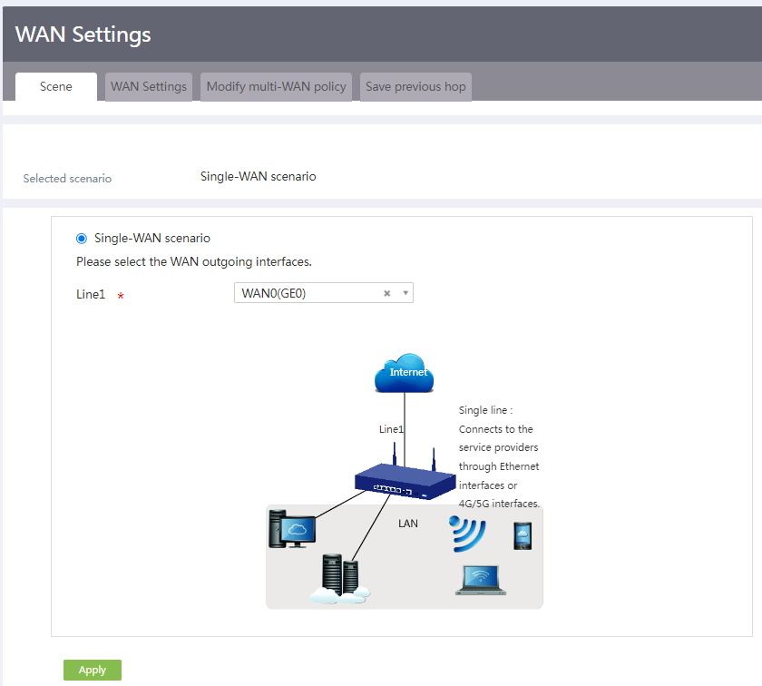
# From the navigation pane, select Network > WAN Settings. Click the Scene tab, select the single-WAN scenario, and select interface WAN0, as shown in the following figure.
Figure 2 Scene

# Click Apply.
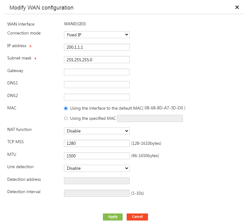
# Select WAN Settings. Click the Edit icon for interface WAN0. On the page that opens, disable NAT, as shown in the following figure.
Figure 3 Configuring a WAN interface

# Click OK.
Configuring a LAN interface
# From the navigation pane, select Network > LAN Settings. Click the Edit icon in the Actions column for interface VLAN-interface 1. On the page that opens, configure the parameters as shown in the following figure.
Figure 4 Configuring a LAN interface
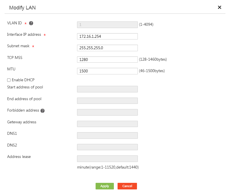
# Click OK.
Creating a PPP user
# From the navigation pane, select Authentication > User Management. Click Add. On the Add User page that opens, configure parameters as shown in the following figure (the user password is 123456).
Figure 5 Creating a PPP user

# Click OK.
Configuring the L2TP server (LNS)
# Select Virtual Private Network > L2TP Server > L2TP Config. Select Enable to enable the L2TP server feature, as shown in the following figure.
Figure 6 Enabling the L2TP server feature

# Click Add to access the L2TP server configuration page. Configure the parameters as shown in the following figure (configure the tunnel authentication password as abc123).
Figure 7 Configuring the L2TP server
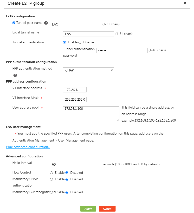
# Click OK.
Configuring static routes
# From the navigation pane, select Advanced Settings > Static Routing. Click Add. On the static route configuration page that opens, configure the route to the branch private network address as shown in the following figure:
Figure 8 Configuring a static route

# Click OK.
Configuring the L2TP client (LAC)
Configuring a WAN interface
# From the navigation pane, select Network > WAN Settings. Click the Scene tab, select the single-WAN scenario, and select interface WAN0, as shown in the following figure.
Figure 9 Scene
# Click Apply.
# Select WAN Settings. Click the Edit icon for interface WAN0. On the page that opens, disable NAT, as shown in the following figure.
Figure 10 Configuring a WAN interface
# Click OK.
Configuring a LAN interface
# From the navigation pane, select Network > LAN Settings. Click the Edit icon in the Actions column for interface VLAN-interface 1. On the page that opens, configure the parameters as shown in the following figure.
Figure 11 Configuring a LAN interface

# Click OK.
Configuring the L2TP client (LAC)
# Select Virtual Private Network > L2TP Client > L2TP Config. Select Enable to enable the L2TP client feature, as shown in the following figure.
Figure 12 Enabling the L2TP client feature

# Click Add to access the L2TP client configuration page. Configure the parameters as shown in the following figure (configure the tunnel authentication password as abc123 and the user password as 123456).
Figure 13 Configuring the L2TP client
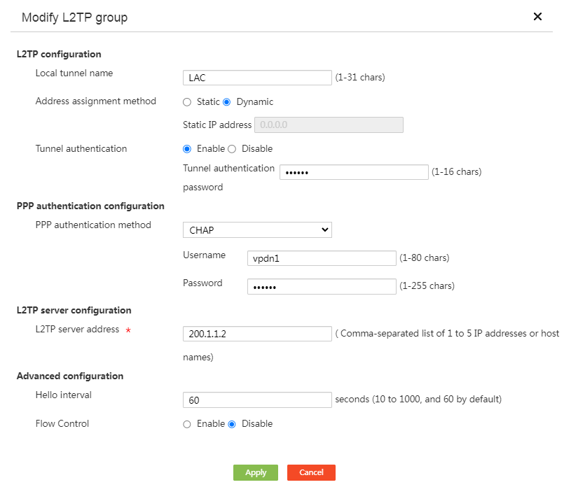
# Click OK.
Configuring static routes
# From the navigation pane, select Advanced Settings > Static Routing. Click Add. On the static route configuration page that opens, configure parameters as shown in the following figure.
Figure 14 Configuring a static route
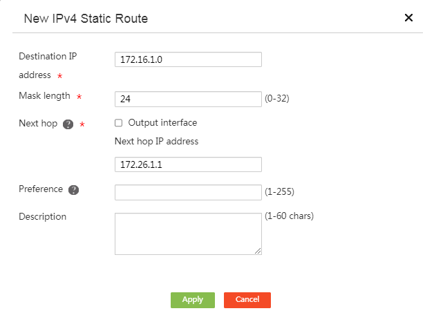
# Click OK.
Configuring the host
# Configure the host to automatically obtain an IP address.
Figure 15 Configuring the host to automatically obtain an IP address

Verifying the configuration
Viewing tunnel information on the L2TP server (LNS)
# From the navigation pane, select Virtual Network > L2TP Server. Click the Tunnel Information tab. On this tab, you can view information about the established L2TP tunnels.
Figure 16 Tunnel information on the L2TP server
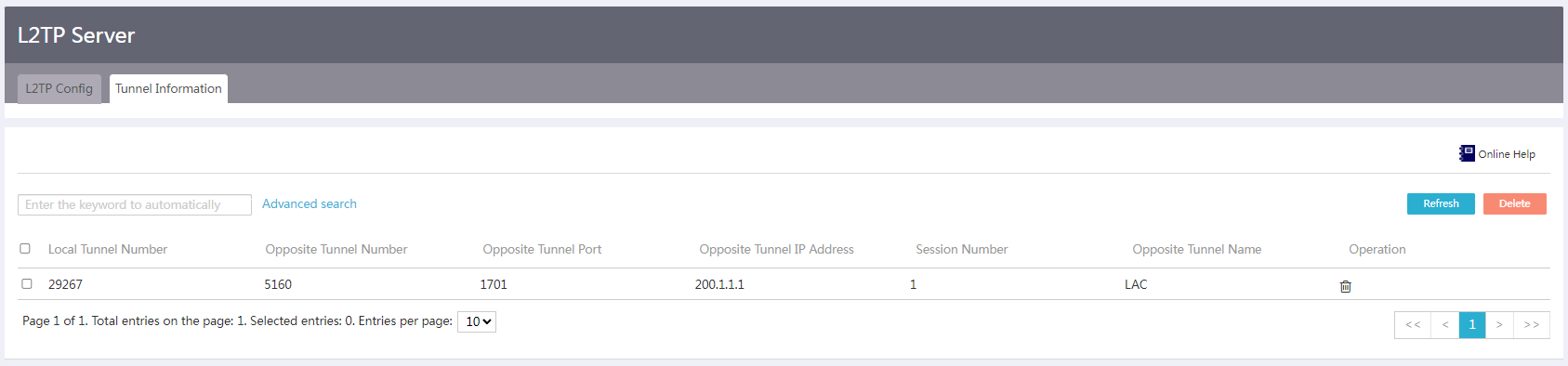
# Verify that the L2TP server (LNS) has successfully established an L2TP tunnel with the L2TP client (LAC).
Viewing tunnel information on the L2TP client (LAC)
# From the navigation pane, select Virtual Network > L2TP Client. Click the Tunnel Information tab. On this tab, you can view information about the established L2TP tunnels.
Figure 17 Viewing tunnel information on the L2TP client
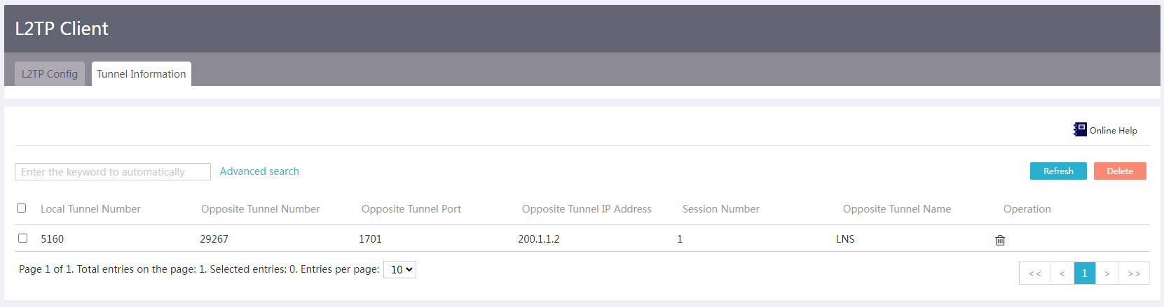
# Verify that the L2TP client (LAC) has successfully established an L2TP tunnel with the L2TP server (LNS).
Accessing the HQ-side internal network server from the branch-side host
# Use the ping command on the branch-side host to test the connectivity to the HQ-side internal network server.
Ping 192.168.100.100 (192.168.100.100): 56 bytes
56 bytes from 192.168.100.100: Sequence number=0, TTL=255, time=1.281 milliseconds
56 bytes from 192.168.100.100: Sequence number=1, TTL=255, time=0.687 milliseconds
56 bytes from 192.168.100.100: Sequence number=2, TTL=255, time=0.671 milliseconds
56 bytes from 192.168.100.100: Sequence number=3, TTL=255, time=0.692 milliseconds
56 bytes from 192.168.100.100: Sequence number=4, TTL=255, time=0.609 milliseconds
--- Ping statistics for 192.168.100.100 ---
5 packets sent
5 packets received
0% loss
Round-trip time: minimum/average/maximum/standard deviation=0.609/0.788/1.281/0.248 ms
Accessing the branch-side host from the HQ-side internal network
# Use the ping command to test the connectivity to the branch-side host from the HQ-side internal network device.
Ping 192.168.100.100 (192.168.100.100): 56 bytes
56 bytes from 192.168.100.100: Sequence number=0, TTL=255, time=1.101 milliseconds
56 bytes from 192.168.100.100: Sequence number=1, TTL=255, time=0.736 milliseconds
56 bytes from 192.168.100.100: Sequence number=2, TTL=255, time==0.681 milliseconds
56 bytes from 192.168.100.100: Sequence number=3, TTL=255, time=0.749 milliseconds
56 bytes from 192.168.100.100: Sequence number=4, TTL=255, time=0.620 milliseconds
--- Ping statistics for 192.168.100.100 ---
5 packets sent
5 packets received
0% loss
Round-trip time: minimum/average/maximum/standard deviation=0.620/0.777/1.101/0.168 ms
