- Table of Contents
-
- 01-Fundamentals Configuration Guide
- 00-Preface
- 01-CLI Configuration
- 02-Login Management Configuration
- 03-FTP and TFTP Configuration
- 04-File System Management Configuration
- 05-Configuration File Management Configuration
- 06-Software Upgrade Configuration
- 07-License Management
- 08-Device Management Configuration
- 09-Automatic Configuration
- Related Documents
-
| Title | Size | Download |
|---|---|---|
| 08-Device Management Configuration | 166.95 KB |
Enabling displaying the copyright statement
Configuring the maximum number of concurrent users
Configuring the exception handling method
Rebooting devices immediately at the CLI
Scheduling a job in the non-modular approach
Scheduling a job in the modular approach·
Scheduled job configuration example
Setting the port status detection timer
Configuring temperature thresholds for a card
Configuring the temperature thresholds (basic)
Configuring temperature thresholds (advanced)
Configuring the alarm resend function
Monitoring an NMS-connected interface
Clearing unused 16-bit interface indexes
Verifying and diagnosing transceiver modules
Diagnosing transceiver modules
Displaying and maintaining device management
Managing the device
Overview
Device management includes monitoring the operating status of devices and configuring their running parameters.
The configuration tasks in this document are order independent. You can perform these tasks in any order.
Storage media include Flash, CF card, USB disk, and hard disk. Different devices support different storage media. For more information, see About the H3C Access Controllers Configuration Guides. Flash and CF card are used in the examples throughout this chapter.
Configuring the device name
A device name identifies a device in a network and works as the user view prompt at the CLI. For example, if the device name is Sysname, the user view prompt is <Sysname>.
To configure the device name:
|
Step |
Command |
Remarks |
|
1. Enter system view. |
system-view |
N/A |
|
2. Configure the device name. |
sysname sysname |
The default device name is H3C. |
Changing the system time
You must synchronize your device with a trusted time source by using NTP or changing the system time before you run it on the network. Network management depends on an accurate system time setting, because the timestamps of system messages and logs use the system time. For NTP configuration, see Network Management and Monitoring Configuration Guide.
In a small-sized network, you can manually set the system time of each device.
Configuration guidelines
You can change the system time by configuring the relative time, time zone, and daylight saving time. The configuration result depends on their configuration order (see Table 1). In the first column of this table, 1 represents the clock datetime command, 2 represents the clock timezone command, and 3 represents the clock summer-time command. To verify the system time setting, use the display clock command. This table assumes that the original system time is 2005/1/1 1:00:00.
Table 1 System time configuration results
|
Command |
Effective system time |
Configuration example |
System time |
|
1 |
date-time |
01:00:00 UTC Mon 01/01/2007. |
|
|
2 |
Original system time ± zone-offset |
02:00:00 zone-time Sat 01/01/2005. |
|
|
1, 2 |
date-time ± zone-offset |
03:00:00 zone-time Fri 02/02/2007. |
|
|
2, 1 |
date-time |
03:00:00 zone-time Sat 03/03/2007. |
|
|
3 |
The original system time outside the daylight saving time range: The system time does not change until it falls into the daylight saving time range. |
01:00:00 UTC Sat 01/01/2005. |
|
|
The original system time in the daylight saving time range: The system time increases by summer-offset. |
03:00:00 ss Sat 01/01/2005. If the original system time plus summer-offset is beyond the daylight saving time range, the original system time does not change. After you disable the daylight saving setting, the system time automatically decreases by summer-offset. |
||
|
1, 3 |
date-time outside the daylight saving time range: date-time |
01:00:00 UTC Mon 01/01/2007. |
|
|
date-time in the daylight saving time range: date-time + summer-offset |
10:00:00 ss Mon 01/01/2007. If the date-time plus summer-offset is outside the daylight saving time range, the system time equals date-time. After you disable the daylight saving setting, the system time automatically decreases by summer-offset. |
||
|
3, 1 (date-time outside the daylight saving time range) |
date-time |
01:00:00 UTC Tue 01/01/2008. |
|
|
3, 1 (date-time in the daylight saving time range) |
date-time – summer-offset outside the daylight saving time range: date-time – summer-offset |
23:30:00 UTC Sun 12/31/2006. |
|
|
date-time – summer-offset in the daylight saving time range: date-time |
03:00:00 ss Mon 01/01/2007. |
||
|
2, 3 or 3, 2 |
Original system clock ± zone-offset outside the daylight saving time range: Original system clock ± zone-offset |
02:00:00 zone-time Sat 01/01/2005. |
|
|
Original system clock ± zone-offset outside the daylight saving time range: Original system clock ± zone-offset + summer-offset |
System clock configured: 04:00:00 ss Sat 01/01/2005. |
||
|
1, 2, 3 or 1, 3, 2 |
date-time ± zone-offset outside the daylight saving time range: date-time ± zone-offset |
02:00:00 zone-time Mon 01/01/2007. |
|
|
date-time ± zone-offset outside the daylight saving time range: date-time ± zone-offset + summer-offset |
04:00:00 ss Mon 01/01/2007. |
||
|
2, 3, 1 or 3, 2, 1 |
date-time outside the daylight saving time range: date-time |
01:00:00 zone-time Mon 01/01/2007. |
|
|
date-time in the daylight saving time range, but date-time – summer-offset outside the summer-time range: date-time – summer-offset |
23:30:00 zone-time Mon 12/31/2007. |
||
|
Both date-time and date-time – summer-offset in the daylight saving time range: date-time |
03:00:00 ss Tue 01/01/2008. |
Configuration procedure
To change the system time:
|
Step |
Command |
Remarks |
|
1. Set the system time and date. |
clock datetime time date |
Optional. Available in user view. |
|
2. Enter system view. |
system-view |
N/A |
|
3. Set the time zone. |
clock timezone zone-name { add | minus } zone-offset |
Optional. Coordinated UTC time zone by default. |
|
4. Set a daylight saving time scheme. |
· Set a non-recurring scheme: · Set a recurring scheme: |
Optional. Use either command. By default, daylight saving time is disabled, and the UTC time zone applies. |
Enabling displaying the copyright statement
The device by default displays the copyright statement when a Telnet or SSH user logs in, or when a console user quits user view. You can disable or enable the function as needed. The following is a sample copyright statement:
******************************************************************************
* Copyright (c) 2004-2017 New H3C Technologies Co., Ltd. All rights reserved.*
* Without the owner's prior written consent, *
* no decompiling or reverse-engineering shall be allowed. *
******************************************************************************
To enable displaying the copyright statement:
|
Step |
Command |
Remarks |
|
1. Enter system view. |
system-view |
N/A |
|
2. Enable displaying the copyright statement. |
copyright-info enable |
Enabled by default. |
Configuring banners
Banners are messages that the system displays during user login.
The system supports the following banners:
· Legal banner—Appears after the copyright or license statement. To continue login, the user must enter Y or press Enter. To quit the process, the user must enter N. Y and N are case-insensitive.
· Message of the Day (MOTD) banner—Appears after the legal banner and before the login banner.
· Login banner—Appears only when password or scheme authentication has been configured.
· Incoming banner—Appears for modem users.
· Shell banner—Appears for non-modem users.
Banner message input modes
You can configure a banner in one of the following ways:
· Single-line input
Input the entire banner in the same line as the command. The start and end delimiters for the banner must be the same, but can be any visible character. The input text, including the command keywords and the delimiters cannot exceed 510 characters. In this mode, do not press Enter before you input the end delimiter. For example, you can configure the shell banner "Have a nice day." as follows:
<System> system-view
[System] header shell %Have a nice day.%
· Multiple-line input
Input message text in multiple lines. In this approach, the message text can be up to 2000 characters. Use one of the following methods to implement multi-line input mode:
¡ Method 1—Press Enter after the last command keyword. At the system prompt, enter the banner message and end with the delimiter character %. For example, you can configure the banner "Have a nice day. Please input the password." as follows:
<System> system-view
[System] header shell
Please input banner content, and quit with the character '%'.
Have a nice day.
Please input the password.%
¡ Method 2—After you type the last command keyword, type any single character as the start delimiter for the banner and press Enter. At the system prompt, type the banner and end the last line with a delimiter that is the same as the start delimiter. For example, you can configure the banner "Have a nice day. Please input the password." as follows:
<System> system-view
[System] header shell A
Please input banner content, and quit with the character 'A'.
Have a nice day.
Please input the password.A
¡ Method 3—After you type the last keyword, type the start delimiter and part of the banner and press Enter. At the system prompt, enter the rest of the banner and end the last line with a delimiter that is the same as the start delimiter. For example, you can configure the banner "Have a nice day. Please input the password." as follows:
<System> system-view
[System] header shell AHave a nice day.
Please input banner content, and quit with the character 'A'.
Please input the password.A
Configuration procedure
To configure banners:
|
Step |
Command |
|
1. Enter system view. |
system-view |
|
2. Configure the incoming banner. |
header incoming text |
|
3. Configure the login banner. |
header login text |
|
4. Configure the legal banner. |
header legal text |
|
5. Configure the shell banner. |
header shell text |
|
6. Configure the MOTD banner. |
header motd text |
Configuring the maximum number of concurrent users
You can configure this command to limit the number of users that can enter the system view simultaneously. When the number of concurrent users reaches the upper limit, other users cannot enter system view.
When multiple users configure a setting in system view, only the last configuration applies.
To configure the maximum number of concurrent users:
|
Step |
Command |
Remarks |
|
1. Enter system view. |
system-view |
N/A |
|
2. Configure the maximum number of concurrent users. |
configure-user count number |
By default, up to two users can perform operations in system view at the same time. |
Configuring the exception handling method
You can configure the device to handle system exceptions in one of the following methods:
· reboot—The device automatically reboots to recover from the error condition.
· maintain—The device stays in the error condition so you can collect complete data, including error messages, for diagnosis. In this approach, you must manually reboot the device.
To configure the exception handling method:
|
Step |
Command |
Remarks |
|
1. Enter system view. |
system-view |
N/A |
|
2. Configure the exception handling method for the system. |
system-failure { maintain | reboot } |
By default, the system uses the reboot method when an exception occurs. |
Rebooting the device
|
|
CAUTION: · Device reboot can interrupt network services. · To avoid data loss, use the save command to save the current configuration before a reboot. · Use the display startup and display boot-loader commands to verify that you have correctly set the startup configuration file and the main system software image file. If the main system software image file has been corrupted or does not exist, the device cannot reboot. You must re-specify a main system software image file, or power off the device and then power it on so the system can reboot with the backup system software image file. |
You can reboot the device in one of the following ways to recover from an error condition:
· Reboot the device immediately at the CLI.
· At the CLI, schedule a reboot to occur at a specific time and date or after a delay.
· Power off and then power on the device. This method might cause data loss, and is the least-preferred method.
Reboot at the CLI enables easy remote device maintenance.
Rebooting devices immediately at the CLI
To reboot a device, execute the following command in user view:
|
Task |
Command |
|
Reboot the device immediately. |
reboot |
Scheduling a device reboot
The switch supports only one device reboot schedule. If you configure the schedule reboot delay command multiple times, the last configuration takes effect. The schedule reboot at command and the schedule reboot delay command overwrite each other, and whichever is configured last takes effect.
For data security, if you are performing file operations at the reboot time, the system does not reboot.
To schedule a device reboot, execute one of the following commands in user view:
|
Task |
Command |
Remarks |
|
Schedule a reboot. |
· Schedule a reboot to occur at a specific time
and date: · Schedule a reboot to occur after a delay: |
Use either command. The scheduled reboot function is disabled by default. Changing any clock setting can cancel the reboot schedule. |
Scheduling jobs
You can schedule a job to automatically run a command or a set of commands without administrative interference. The commands in a job are polled every minute. When the scheduled time for a command is reached, the job automatically executes the command. If a confirmation is required while the command is running, the system automatically enters Y or Yes. If characters are required, the system automatically enters a default character string or an empty character string when no default character string is available.
Job configuration approaches
You can configure jobs in a non-modular or modular approach. Use the non-modular approach for a one-time command execution and use non-modular approach for complex maintenance work.
Table 2 A comparison of non-modular and modular approaches
|
Comparison item |
||
|
Configuration method |
Configure all elements in one command. |
Separate job, view, and time settings. |
|
Can multiple jobs be configured? |
No. |
Yes. |
|
Can a job have multiple commands? |
No. If you use the schedule job command multiple times, the most recent configuration takes effect. |
Yes. You can use the time command in job view to configure commands to be executed at different time points. |
|
Supported views |
User view and system view. In the schedule job command, shell represents user view, and system represents system view. |
All views. In the time command, monitor represents user view. |
|
Supported commands |
Commands in user view and system view. |
Commands in all views. |
|
Can a job be executed multiple times? |
No. |
Yes. |
|
Can a job be saved? |
No. |
Yes. |
Configuration guidelines
· To have a job successfully run a command, make sure the specified view and command are valid. The system does not verify their validity.
· After job execution, the configuration interface, view, and user status that you have before job execution restores even if the job ran a command to change the user interface (for example, telnet, ftp, and ssh2), the view (for example, system-view and quit), or the user status (for example, super).
· The jobs run in the background without displaying any messages except log, trap and debugging messages.
· In the modular approach:
¡ Every job can have only one view and up to 10 commands. If you specify multiple views, the one specified last takes effect.
¡ Enter a view name in its complete form. Most commonly used view names include monitor for user view, system for system view, GigabitEthernet x/x/x for Ethernet interface view, and Vlan-interfacex for VLAN interface view.
¡ The time ID (time-id) must be unique in a job. If two time and command bindings have the same time ID, the one configured last takes effect.
Scheduling a job in the non-modular approach
To schedule a job, execute one of the following commands in user view:
|
Task |
Command |
Remarks |
|
Schedule a job. |
· Schedule a job to run a command at a specific
time: · Schedule a job to run a command after a
delay: |
Use either command. NOTE: · If you execute the schedule job command multiple times, the most recent configuration takes effect. · Changing any clock setting can cancel the job set by using the schedule job command. |
Scheduling a job in the modular approach
To configure a scheduled job:
|
Step |
Command |
Remarks |
|
1. Enter system view. |
system-view |
N/A |
|
2. Create a job and enter job view. |
job job-name |
N/A |
|
3. Specify the view in which the commands in the job run. |
view view-name |
You can specify only one view for a job. The job executes all commands in the specified view. |
|
4. Add commands to the job. |
· Configure a command to run at a
specific time and date: · Configure a command to run at a
specific time: · Configure a command to run after a
delay: |
Use any of the commands. NOTE: Changing a clock setting does not affect the schedule set by using the time at or time delay command. |
Scheduled job configuration example
Network requirements
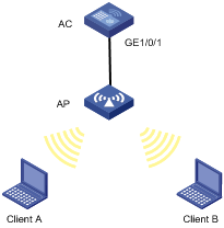
To control access to the AC interface, configure scheduled jobs on the AC to enable interface GigabitEthernet 1/0/1 at 8:00 and disabled it at 18:00 on working days every week.
Figure 1 Network diagram
Configuration procedure
# Enter system view.
<AC> system-view
# Create scheduled job client, and enter its view.
[AC] job client
# Specify the command view.
[AC-job-client] view gigabitethernet1/0/1
# Add a command to enable GigabitEthernet 1/0/1 at 8:00 on working days every week.
[AC-job-client] time 1 repeating at 8:00 week-day mon tue wed thu fri command undo shutdown
# Add a command to disable GigabitEthernet 1/0/1 at 18:00 on working days every week.
[AC-job-client] time 2 repeating at 18:00 week-day mon tue wed thu fri command shutdown
[AC-job-client] quit
# Display information about scheduled jobs.
[AC] display job
Job name: client
Specified view: gigabitethernet1/0/1
Time 1: Execute command undo shutdown at 08:00 Mondays Tuesdays Wednesdays Thursdays Fridays
Time 2: Execute command shutdown at 18:00 Mondays Tuesdays Wednesdays Thursdays Fridays
Setting the port status detection timer
Some protocols might shut down ports under specific circumstances. For example, MSTP shuts down a BPDU guard–enabled port when the port receives a BPDU. In this case, you can set the port status detection timer. If the port is still down when the detection timer expires, the protocol module automatically cancels the shutdown action and restores the port to its original physical status.
To set the port status detection timer:
|
Step |
Command |
Remarks |
|
1. Enter system view. |
system-view |
N/A |
|
2. Set the port status detection timer. |
shutdown-interval time |
By default, the port status detection timer is 30 seconds. |
Configuring temperature thresholds for a card
Configuring the temperature thresholds (basic)
You can set the temperature threshold to monitor the temperature of a card. When the temperature reaches the threshold, the device generates alarms.
Support for this feature depends on your device model. For more information, see About the H3C Access Controllers Configuration Guides.
To configure the temperature threshold:
|
Step |
Command |
Remarks |
|
1. Enter system view. |
system-view |
N/A |
|
2. Configure the temperature threshold for a card. |
temperature-limit slot-number lower-value upper-value |
By default, the temperature threshold varies with devices. For more information, see About the H3C Access Controllers Command References. |
Configuring temperature thresholds (advanced)
You can set the temperature thresholds to monitor the temperature of a card.
· When the temperature drops below the lower threshold or reaches the warning threshold, the device logs the event and outputs a log message and a trap.
· When the temperature reaches the alarming threshold, the device logs the event and outputs a log message and a trap repeatedly in the terminal display, and alerts users through the LED on the device panel.
Support for this feature depends on your device model. For more information, see About the H3C Access Controllers Configuration Guides.
To configure temperature thresholds:
|
Step |
Command |
Remarks |
|
1. Enter system view. |
system-view |
N/A |
|
2. Configure temperature thresholds for a card. |
temperature-limit slot slot-number { inflow | hotspot } sensor-number lowerlimit warninglimit [ alarmlimit ] |
By default, the temperature thresholds for a card vary with devices. For more information, see About the H3C Access Controllers Command References. The warning and alarming thresholds must be higher than the lower temperature threshold. The alarming threshold must be higher than the warning threshold. |
Configuring the alarm resend function
When an AP is running, it may encounter high CPU usage or high memory usage. If you do not configure the alarm resend function on an AC, the AC does not collect CPU or memory statistics or send the statistics though you can use the display cpu or display memory command to view such information.
After you configure the alarm resend function on the AC, the AC collects the CPU or memory statistics of a specific AP at an interval (specified by the collection-interval argument). In a resend interval (specified by the resend-interval argument), if any two of the last three collected usage values reach or exceed the threshold (specified by the cpu-threshold argument or memory-threshold argument), the AC sends a high CPU usage alarm or high memory usage alarm to you when the monitoring period expires, and starts the next resend interval.
When you set the alarm resend interval and the interval for collecting CPU/memory statistics to a non-zero value, you must set the alarm resend interval first and make sure the alarm resend interval is larger than or equal to three times the interval for collecting CPU/memory statistics. When you restore the alarm resend interval and the interval for collecting CPU/memory statistics to their default, set the interval for collecting CPU/memory statistics first. Otherwise, the commands cannot be executed successfully.
To configure the alarm resend function:
|
Step |
Command |
Remarks |
|
|
1. Enter system view. |
system-view |
N/A |
|
|
2. Set the alarm resend interval. |
resend-interval resend-interval |
0 by default. |
|
|
3. Set the interval for collecting CPU/memory statistics. |
collection-interval collection-interval |
0 by default. |
|
|
4. Enter AP template view. |
wlan ap ap-name model model-name [ id ap-id ] |
N/A |
|
|
5. Specify the CPU usage threshold for the AP. |
cpu-usage threshold cpu-threshold |
Optional. The default value is 90%. |
|
|
6. Specify the memory usage threshold for the AP. |
memory-usage threshold memory-threshold |
Optional. The default value is 90%. |
|
Monitoring an NMS-connected interface
Typically, the device does not send notifications to its NMS when the IP address of an interface changes. If the IP address of the interface used by the device to communicate with the NMS changes, the NMS will be unable to communicate with the device unless the new management IP address of the device is updated manually or the device is re-added with the new IP address to the NMS database.
To ensure management continuity, you can configure the device to monitor the NMS connected interface for IP address changes and notify the NMS to update with the new IP address for communicating with the device.
You can configure one primary and one secondary interface for the device to communicate with the NMS, but the device monitors only one of them for IP address change at one time. If the IP address of the monitored interface in UP state changes, whether because of manual reassignment or DHCP reassignment, the device notifies the NMS of the new IP address. The IP address changes of the interface not under monitor will be ignored.
The device preferentially monitors the primary interface. H3C recommends you specify the interface that has better route or more reliable link as the primary.
The device changes the monitored interface only when the interface goes down, the interface IP address is deleted, or the role of the interface is removed by using the undo nms { primary | secondary } monitor-interface command.
Before you specify NMS-connected interfaces, make sure you have configured the NMS as the SNMP notification destination host. For more information, see Network Management and Monitoring Configuration Guide.
To monitor NMS-connected interfaces:
|
Step |
Command |
Remarks |
|
1. Enter system view. |
system-view |
N/A |
|
2. Specify NMS-connected interfaces. |
· Specify the primary interface: · Specify the secondary interface: |
Configure at least one command. By default, no interfaces are configured as NMS-connected interfaces to be monitored. The monitoring function only applies to interfaces that use IPv4 addresses. |
Clearing unused 16-bit interface indexes
The device must maintain persistent 16-bit interface indexes and keep one interface index match one interface name for network management. After deleting a logical interface, the device retains its 16-bit interface index so the same index can be assigned to the interface at interface re-creation.
To avoid index depletion causing interface creation failures, you can clear all 16-bit indexes that have been assigned but not in use. The operation does not affect the interface indexes of the interfaces that have been created but the indexes assigned to re-recreated interfaces might change.
A confirmation is required when you execute this command. The command will not run if you fail to make a confirmation within 30 seconds or enter N to cancel the operation.
To clear unused 16-bit interface indexes, execute one of the following commands in user view:
|
Task |
Command |
|
Clear unused 16-bit interface indexes. |
reset unused porttag |
Verifying and diagnosing transceiver modules
This section describes how to verify and diagnose transceiver modules.
Support for the transceiver modules and the transceiver module type depends on your device model. For more information, see About the H3C Access Controllers Configuration Guides.
Verifying transceiver modules
You can verify the genuineness of a transceiver module in the following ways:
· Display the key parameters of a transceiver module, including its transceiver type, connector type, central wavelength of the transmit laser, transfer distance and vendor name.
· Display its electronic label. The electronic label is a profile of the transceiver module and contains the permanent configuration including the serial number, manufacturing date, and vendor name. The data is written to the storage component during debugging or testing.
To verify transceiver modules, execute the following commands in any view:
|
Task |
Command |
|
Display key parameters of the transceiver modules. |
display transceiver interface [ interface-type interface-number ] [ | { begin | exclude | include } regular-expression ] |
|
Display transceiver modules' electrical label information. |
display transceiver manuinfo interface [ interface-type interface-number ] [ | { begin | exclude | include } regular-expression ] |
Diagnosing transceiver modules
The device provides the alarm function and digital diagnosis function for transceiver modules. When a transceiver module fails or works inappropriately, you can examine the alarms on the transceiver module to identify the fault source or examine the key parameters monitored by the digital diagnosis function, including the temperature, voltage, laser bias current, TX power, and RX power.
To diagnose transceiver modules, execute the following commands in any view:
|
Step |
Command |
|
1. Display alarms on transceiver modules. |
display transceiver alarm interface [ interface-type interface-number ] [ | { begin | exclude | include } regular-expression ] |
|
2. Display the measured values of the digital diagnosis parameters for transceiver modules. |
display transceiver diagnosis interface [ interface-type interface-number ] [ | { begin | exclude | include } regular-expression ] |
|
3. Enter system view. |
system-view |
|
4. Disable alarm traps for transceiver modules. |
transceiver phony-alarm-disable |
Enabling USB power supply
You can enable USB power supply for APs that have USB ports so the APs supply power for devices connected to their USB ports.
To enable USB power supply:
|
Step |
Command |
Remarks |
|
1. Enter system view. |
system-view |
N/A |
|
2. Enter AP template view or AP group view. |
· wlan ap ap-name [ model model-name [ id ap-id ] ] · wlan ap-group group-name |
N/A |
|
3. Enable USB power supply. |
usb-power-supply enable |
By default, USB power supply is enabled. |
Displaying and maintaining device management
For diagnosis or troubleshooting, you can use separate display commands to collect running status data module by module, or use the display diagnostic-information command to bulk collect running data for multiple modules.
|
Task |
Command |
Remarks |
|
Display system version information. |
display version [ | { begin | exclude | include } regular-expression ] |
Available in any view. |
|
Display the system time and date. |
display clock [ | { begin | exclude | include } regular-expression ] |
Available in any view. |
|
Display information about the users that have logged in to the device but are not under user view. |
display configure-user [ | { begin | exclude | include } regular-expression ] |
Available in any view. |
|
Display the software and hardware copyright statements. |
display copyright [ | { begin | exclude | include } regular-expression ] |
Available in any view. |
|
Display or save running status data for multiple feature modules. |
display diagnostic-information [ | { begin | exclude | include } regular-expression ] |
Available in any view. |
|
Display CPU usage statistics. |
display cpu-usage [ entry-number [ offset ] [ verbose ] [ from-device ] ] [ | { begin | exclude | include } regular-expression ] |
Available in any view. |
|
Display historical CPU usage statistics in charts. |
display cpu-usage history [ task task-id ] [ | { begin | exclude | include } regular-expression ] |
Available in any view. |
|
Display device information. |
display device [ cf-card | usb ] [ subslot subslot-number | verbose ] [ | { begin | exclude | include } regular-expression ] |
Available in any view. |
|
Display the electronic label data for the device. |
display device manuinfo [ subslot subslot-number ] [ | { begin | exclude | include } regular-expression ] |
Available in any view. |
|
Display device temperature information. |
display environment [ cpu ] [ | { begin | exclude | include } regular-expression ] |
Available in any view. Support for this command depends on your device model. For more information, see About the H3C Access Controllers Command References. |
|
Display the operating states of fans. |
display fan [ fan-id ] [ | { begin | exclude | include } regular-expression ] |
Available in any view. Support for this command depends on your device model. For more information, see About the H3C Access Controllers Command References. |
|
Display memory usage statistics. |
display memory [ | { begin | exclude | include } regular-expression ] |
Available in any view. |
|
Display the power state. |
display power [ power-id ] [ | { begin | exclude | include } regular-expression ] |
Available in any view. Support for this command depends on your device model. For more information, see About the H3C Access Controllers Command References. |
|
Display RPS state information. |
display rps [ rps-id ] [ | { begin | exclude | include } regular-expression ] |
Available in any view. Support for this command depends on your device model. For more information, see About the H3C Access Controllers Command References. |
|
Display the mode of the last reboot. |
display reboot-type [ subslot subslot-number ] [ | { begin | exclude | include } regular-expression ] |
Available in any view. |
|
Display the configuration of the job configured by using the schedule job command. |
display schedule job [ | { begin | exclude | include } regular-expression ] |
Available in any view. |
|
Display the reboot schedule. |
display schedule reboot [ | { begin | exclude | include } regular-expression ] |
Available in any view. |
|
Display the configuration of jobs configured by using the job command. |
display job [ job-name ] [ | { begin | exclude | include } regular-expression ] |
Available in any view. |
|
Display the exception handling method. |
display system-failure [ | { begin | exclude | include } regular-expression ] |
Available in any view. |
|
Display the system software update history. |
display version-update-record [ | { begin | exclude | include } regular-expression ] |
Available in any view. |
|
Clear the system software update history. |
reset version-update-record |
Available in any view. |