- Table of Contents
- Related Documents
-
| Title | Size | Download |
|---|---|---|
| 03-H3C S12500 VLAN Configuration Examples | 173.11 KB |
Contents
Example: Configuring port-based VLANs
Configuration restrictions and guidelines
Example: Configuring the super VLAN
Configuration restrictions and guidelines
Example: Configuring the private VLAN
Configuration restrictions and guidelines
Introduction
This document provides examples of configuring the port-based VLAN, super VLAN, and private VLAN.
Prerequisites
The configuration examples in this document were created and verified in a lab environment, and all the devices were started with the factory default configuration. When you are working on a live network, make sure you understand the potential impact of every command on your network.
This document assumes that you have basic knowledge of H3C VLANs.
Example: Configuring port-based VLANs
Network requirements
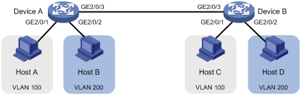
As shown in Figure 1:
· Host A and Host C belong to Department A. VLAN 100 is assigned to Department A.
· Host B and Host D belong to Department B. VLAN 200 is assigned to Department B.
Configure port-based VLANs so that hosts only in the same department can communicate with each other.
Software version used
This configuration example was created and verified on S12500-CMW710-R7328P02.
Configuration restrictions and guidelines
By default, Ethernet, VLAN, and aggregate interfaces are shut down. You must use the undo shutdown command to bring them up. The examples assume that all these interfaces are already up.
Configuration procedures
# Configure the ports GigabitEthernet 2/0/1 through GigabitEthernet 2/0/3 to operate in bridge mode.
[DeviceA] interface range gigabitethernet 2/0/1 to gigabitethernet 2/0/3
[DeviceA-if-range] port link-mode bridge
[DeviceA-if-range] quit
# Create VLAN 100, and assign GigabitEthernet 2/0/1 to VLAN 100.
[DeviceA-vlan100] port gigabitethernet 2/0/1
[DeviceA-vlan100] quit
# Create VLAN 200, and assign GigabitEthernet 2/0/2 to VLAN 200.
[DeviceA-vlan200] port gigabitethernet 2/0/2
[DeviceA-vlan200] quit
# Configure GigabitEthernet 2/0/3 as a trunk port, and assign it to VLANs 100 and 200.
[DeviceA] interface gigabitethernet 2/0/3
[DeviceA-GigabitEthernet2/0/3] port link-type trunk
[DeviceA-GigabitEthernet2/0/3] port trunk permit vlan 100 200
2. Configure Device B in the same way Device A is configured. (Details not shown.)
3. Configure hosts:
a. Configure Host A and Host C to be on the same IP subnet. For example, 192.168.100.0/24.
b. Configure Host B and Host D to be on the same IP subnet. For example, 192.168.200.0/24.
Verifying the configuration
# Verify that Host B and Host D can ping each other, but they both fail to ping Host A or Host C. (Details not shown.)
# Display information about VLANs 100 and 200 on Device A.
[DeviceA-GigabitEthernet2/0/3] display vlan 100
VLAN ID: 100
VLAN type: Static
Route interface: Not configured
Description: VLAN 0100
Name: VLAN 0100
Tagged ports:
GigabitEthernet2/0/3
Untagged ports:
GigabitEthernet2/0/1
[DeviceA-GigabitEthernet2/0/3] display vlan 200
VLAN ID: 200
VLAN type: Static
Route interface: Not configured
Description: VLAN 0200
Name: VLAN 0200
Tagged ports:
GigabitEthernet2/0/3
Untagged ports:
GigabitEthernet2/0/2
The output shows that:
· GigabitEthernet 2/0/3 and GigabitEthernet 2/0/1 permit packets from 100 to pass through.
· GigabitEthernet 2/0/3 and GigabitEthernet 2/0/2 permit packets from 200 to pass through.
Configuration files
Configuration files on both Device B and Device A are the same. The following configuration files use Device A as an example.
#
vlan 100
#
vlan 200
#
interface GigabitEthernet2/0/1
port link-mode bridge
port access vlan 100
#
interface GigabitEthernet2/0/2
port link-mode bridge
port access vlan 200
#
interface GigabitEthernet2/0/3
port link-mode bridge
port link-type trunk
port trunk permit vlan 1 100 200
#
Example: Configuring the super VLAN
Network requirements
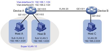
As shown in Figure 2:
· Users in VLAN 2 access the network through GigabitEthernet 1/0/1 of Device A.
· Users in VLAN 3 access the network through GigabitEthernet 1/0/2 of Device A.
· GigabitEthernet 1/0/3 of Device A and GigabitEthernet 1/0/1 of Device B are in VLAN 20.
· Users in VLAN 20 use the gateway address 192.168.2.1 and IP addresses on the IP network segment 192.168.2.0/24.
Configure a super VLAN to meet the following requirements:
· Users in VLAN 2 and VLAN 3 use the gateway address 192.168.1.1 and IP addresses on the IP network segment 192.168.1.0/24.
· Users in VLAN 2, VLAN 3, and VLAN 20 are isolated at Layer 2 but interoperable at Layer 3.
Software version used
This configuration example was created and verified on S12500-CMW710-R7328P02.
Configuration restrictions and guidelines
By default, Ethernet, VLAN, and aggregate interfaces are shut down. You must use the undo shutdown command to bring them up. The examples assume that all these interfaces are already up.
A super VLAN does not have physical ports. A VLAN that has physical ports cannot be configured as a super VLAN.
Configuration procedures
Configuring Device A
# Create VLAN 10 and configure it as a super VLAN.
<DeviceA> system-view
[DeviceA] vlan 10
[DeviceA-vlan10] supervlan
[DeviceA-vlan10] quit
# Create VLAN 2, and assign GigabitEthernet 1/0/1 to VLAN 2.
[DeviceA] vlan 2
[DeviceA-vlan2] port gigabitethernet 1/0/1
[DeviceA-vlan2] quit
# Create VLAN 3, and assign GigabitEthernet 1/0/2 to VLAN 3.
[DeviceA] vlan 3
[DeviceA-vlan3] port gigabitethernet 1/0/2
[DeviceA-vlan3] quit
# Associate super VLAN 10 with VLANs 2 and 3.
[DeviceA] vlan 10
[DeviceA-vlan10] subvlan 2 3
[DeviceA-vlan10] quit
# Create VLAN-interface 10, and assign IP address 192.168.1.1 to it.
[DeviceA] interface vlan-interface 10
[DeviceA-Vlan-interface10] ip address 192.168.1.1 24
# Enable local proxy ARP on VLAN-interface 10.
[DeviceA-Vlan-interface10] local-proxy-arp enable
[DeviceA-Vlan-interface10] quit
# Create VLAN 20.
[DeviceA] vlan 20
[DeviceA-vlan20] quit
# Configure GigabitEthernet 1/0/3 as a trunk port, and remove the port from VLAN 1.
[DeviceA] interface gigabitethernet 1/0/3
[DeviceA-GigabitEthernet1/0/3] port link-type trunk
[DeviceA-GigabitEthernet1/0/3] undo port trunk permit vlan 1
# Assign GigabitEthernet 1/0/3 to VLAN 20.
[DeviceA-GigabitEthernet1/0/3] port trunk permit vlan 20
# Create VLAN-interface 20, and assign IP address 192.168.2.1 to it.
[DeviceA] interface Vlan-interface 20
[DeviceA-Vlan-interface20] ip address 192.168.2.1 24
[DeviceA-Vlan-interface20] quit
Configuring Device B
# Create VLAN 20.
[DeviceB] vlan 20
[DeviceB-vlan20] quit
# Configure GigabitEthernet 1/0/1 as a trunk port, and remove the port from VLAN 1.
[DeviceB] interface gigabitethernet 1/0/1
[DeviceB-GigabitEthernet1/0/1] port link-type trunk
[DeviceB-GigabitEthernet1/0/1] undo port trunk permit vlan 1
# Assign GigabitEthernet 1/0/1 to VLAN 20.
[DeviceB-GigabitEthernet1/0/1] port trunk permit vlan 20
# Assign GigabitEthernet 1/0/2 to VLAN 20.
[DeviceB] vlan 20
[DeviceB-vlan20] port gigabitethernet 1/0/2
[DeviceB-vlan20] quit
Verifying the configuration
# Verify the super VLAN configuration.
[DeviceA] display supervlan
SuperVLAN ID : 10
SubVLAN ID : 2 3
VLAN ID: 10
VLAN Type: static
It is a Super VLAN.
Route Interface: configured
IP Address: 192.168.1.1
Subnet Mask: 255.255.255.0
Description: VLAN 0010
Name: VLAN 0010
Tagged Ports: none
Untagged Ports: none
VLAN ID: 2
VLAN Type: static
It is a Sub VLAN.
Route Interface: configured
IP Address: 192.168.1.1
Subnet Mask: 255.255.255.0
Description: VLAN 0002
Name: VLAN 0002
Tagged Ports: none
Untagged Ports:
GigabitEthernet1/0/1
VLAN ID: 3
VLAN Type: static
It is a Sub VLAN.
Route Interface: configured
IP Address: 192.168.1.1
Subnet Mask: 255.255.255.0
Description: VLAN 0003
Name: VLAN 0003
Tagged Ports: none
Untagged Ports:
GigabitEthernet1/0/2
# Verify that Host A and Host B can ping each other. In the ARP table of Host A, the IP address of Host B corresponds to the MAC address of VLAN-interface 10. In the ARP table of Host B, the IP address of Host A corresponds to the MAC address of VLAN-interface 10. (Details not shown.)
# Verify that Host A and Host C can ping each other. In the ARP table of Host A, no entry about Host C exists. In the ARP table of Host C, no entry about Host A exists. (Details not shown.)
# Verify that Host B and Host C can ping each other. In the ARP table of Host B, no entry about Host C exists. In the ARP table of Host C, no entry about Host B exists. (Details not shown.)
Configuration files
· Device A:
#
vlan 2
#
vlan 3
#
vlan 10
supervlan
subvlan 2 3
#
vlan 20
#
interface Vlan-interface10
ip address 192.168.1.1 255.255.255.0
local-proxy-arp enable
#
interface Vlan-interface20
ip address 192.168.2.1 255.255.255.0
#
interface GigabitEthernet1/0/1
port link-mode bridge
port access vlan 2
#
interface GigabitEthernet1/0/2
port link-mode bridge
port access vlan 3
#
interface GigabitEthernet1/0/3
port link-mode bridge
port link-type trunk
undo port trunk permit vlan 1
port trunk permit vlan 20
#
· Device B:
#
vlan 20
#
interface GigabitEthernet1/0/1
port link-mode bridge
port link-type trunk
undo port trunk permit vlan 1
port trunk permit vlan 20
#
interface GigabitEthernet1/0/2
port link-mode bridge
port access vlan 20
#
Example: Configuring the private VLAN
Network requirements
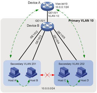
As shown in Figure 3:
· The aggregation-layer device Device A assigns VLAN 10 to Device B. Hosts access the network through VLAN-interface 10.
· Users connected to Device B are on the same subnet 10.0.0.0/24.
· Host A and Host B are in the Marketing department. Host C and Host D are in the Finance department.
Configure the private VLAN feature to meet the following requirements:
· Device A is only aware of the primary VLAN 10.
· Hosts in the same secondary VLAN are interoperable at Layer 2.
· Hosts in different secondary VLANs are isolated at Layer 2.
Requirements analysis
The private VLAN configuration is required only on Device B.
Software version used
This configuration example was created and verified on S12500-CMW710-R7328P02.
Configuration restrictions and guidelines
The system default VLAN (VLAN 1) does not support the private VLAN configuration.
Configuration procedures
Configuring Device B
# Create VLAN 10 and configure it as a primary VLAN.
<DeviceB> system-view
[DeviceB] vlan 10
[DeviceB-vlan10] private-vlan primary
[DeviceB-vlan10] quit
# Create VLANs 201 and 202.
[DeviceB] vlan 201 to 202
# Associate primary VLAN 10 with secondary VLANs 201 and 202.
[DeviceB] vlan 10
[DeviceB-vlan10] private-vlan secondary 201 to 202
[DeviceB-vlan10] quit
# Configure the uplink port GigabitEthernet 1/0/1 as a promiscuous port of VLAN 10.
[DeviceB] interface gigabitethernet 1/0/1
[DeviceB-GigabitEthernet1/0/1] port private-vlan 10 promiscuous
[DeviceB-GigabitEthernet1/0/1] undo shutdown
[DeviceB-GigabitEthernet1/0/1] quit
# Assign the downlink ports GigabitEthernet 1/0/2 and GigabitEthernet 1/0/3 to VLAN 201 as host ports.
[DeviceB] interface range gigabitethernet 1/0/2 to gigabitethernet 1/0/3
[DeviceB-if-range] port link-mode bridge
[DeviceB-if-range] port access vlan 201
[DeviceB-if-range] port private-vlan host
[DeviceB-if-range] undo shutdown
[DeviceB-if-range] quit
# Assign the downlink ports GigabitEthernet 1/0/4 and GigabitEthernet 1/0/5 to VLAN 202 as host ports.
[DeviceB] interface range gigabitethernet 1/0/4 to gigabitethernet 1/0/5
[DeviceB-if-range] port link-mode bridge
[DeviceB-if-range] port access vlan 202
[DeviceB-if-range] port private-vlan host
[DeviceB-if-range] undo shutdown
[DeviceB-if-range] quit
Configuring Device A
# Create VLAN 10.
<DeviceA> system-view
[DeviceA] vlan 10
[DeviceA] quit
# Assign GigabitEthernet 1/0/1 to VLAN 10.
[DeviceA] interface gigabitethernet 1/0/1
[DeviceA-GigabitEthernet1/0/1] port link-mode bridge
[DeviceA-GigabitEthernet1/0/1] port access vlan 10
[DeviceA-GigabitEthernet1/0/1] undo shutdown
[DeviceA-GigabitEthernet1/0/1] quit
# Create VLAN-interface 10, and assign IP address 10.0.0.1 to it.
[DeviceA] interface vlan-interface 10
[DeviceA-Vlan-interface10] ip address 10.0.0.1 24
[DeviceA-Vlan-interface10] undo shutdown
[DeviceA-Vlan-interface10] quit
Verifying the configuration
# Verify that Device A can ping Host A, Host B, Host C, and Host D successfully. (Details not shown.)
# Display the ARP table of Device A.
[DeviceA] display arp
Type: S-Static D-Dynamic O-Openflow M-Multiport I-Invalid
IP address MAC address VLAN Interface Aging Type
10.0.0.2 d485-64a1-7e4a 10 GE1/0/1 19 D
10.0.0.3 7446-a0aa-7774 10 GE1/0/1 19 D
10.0.0.4 6805-ca05-39ae 10 GE1/0/1 20 D
10.0.0.5 6805-ca05-414e 10 GE1/0/1 20 D
# Display the private VLAN configuration on Device B.
[DeviceB] display private-vlan
Primary VLAN ID: 10
Secondary VLAN ID: 201-202
VLAN ID: 10
VLAN type: Static
Private VLAN type: Primary
Route interface: Not configured
Description: VLAN 0010
Name: VLAN 0010
Tagged ports: None
Untagged ports:
GigabitEthernet1/0/1 GigabitEthernet1/0/2
GigabitEthernet1/0/3 GigabitEthernet1/0/4
GigabitEthernet1/0/5
VLAN ID: 201
VLAN type: Static
Private VLAN type: Secondary
Route interface: Not configured
Description: VLAN 0201
Name: VLAN 0201
Tagged ports: None
Untagged ports:
GigabitEthernet1/0/1 GigabitEthernet1/0/2
GigabitEthernet1/0/3
VLAN ID: 202
VLAN type: Static
Private VLAN type: Secondary
Route interface: Not configured
Description: VLAN 0202
Name: VLAN 0202
Tagged ports: None
Untagged ports:
GigabitEthernet1/0/1 GigabitEthernet1/0/4
GigabitEthernet1/0/5
The output shows that:
· The promiscuous port GigabitEthernet1/0/1 is an untagged member of primary VLAN 10 and secondary VLANs 201 and 202.
· The host ports GigabitEthernet 1/0/2 and GigabitEthernet 1/0/3 are untagged members of secondary VLANs 201.
· The host ports GigabitEthernet 1/0/4 and GigabitEthernet 1/0/5 are untagged members of secondary VLANs 202.
# Verify that Hosts in the same secondary VLAN can ping each other, but they fail to ping hosts in the other secondary VLAN. (Details not shown.)
Configuration files
· Device B:
#
vlan 1
#
vlan 10
private-vlan primary
private-vlan secondary 201 to 202
#
vlan 201 to 202
#
interface GigabitEthernet1/0/1
port link-mode bridge
port link-type hybrid
undo port hybrid vlan 1
port hybrid vlan 10 201 to 202 untagged
port hybrid pvid vlan 10
port private-vlan 10 promiscuous
#
interface GigabitEthernet1/0/2
port link-mode bridge
port link-type hybrid
undo port hybrid vlan 1
port hybrid vlan 10 201 untagged
port hybrid pvid vlan 201
port private-vlan host
#
interface GigabitEthernet1/0/3
port link-mode bridge
port link-type hybrid
undo port hybrid vlan 1
port hybrid vlan 10 201 untagged
port hybrid pvid vlan 201
port private-vlan host
#
interface GigabitEthernet1/0/4
port link-mode bridge
port link-type hybrid
undo port hybrid vlan 1
port hybrid vlan 10 202 untagged
port hybrid pvid vlan 202
port private-vlan host
#
interface GigabitEthernet1/0/5
port link-mode bridge
port link-type hybrid
undo port hybrid vlan 1
port hybrid vlan 10 202 untagged
port hybrid pvid vlan 202
port private-vlan host
#
· Device A:
#
vlan 1
#
vlan 10
#
interface Vlan-interface10
ip address 10.0.0.1 255.255.255.0
#
interface GigabitEthernet1/0/1
port link-mode bridge
port access vlan 10
#
Related documentation
· H3C S12500 Routing Switch Series Layer 2—LAN Switching Configuration Guide-Release 7328
· H3C S12500 Routing Switch Series Layer 2—LAN Switching Command Reference-Release 7328