- Table of Contents
- Related Documents
-
| Title | Size | Download |
|---|---|---|
| 01-H3C S12500 Port Isolation Configuration Examples | 156.32 KB |
Contents
General configuration restrictions and guidelines
Example: Configuring port isolation
Configuration restrictions and guidelines
Example: Configuring port isolation with community VLANs
Configuration restrictions and guidelines
Introduction
This document provides port isolation configuration examples.
Prerequisites
This document is not restricted to specific software or hardware versions.
The configuration examples in this document were created and verified in a lab environment, and all the devices were started with the factory default configuration. When you are working on a live network, make sure you understand the potential impact of every command on your network.
This document assumes that you have basic knowledge of port isolation.
General configuration restrictions and guidelines
When you configure port isolation, follow these restrictions and guidelines:
· This feature is not supported on devices enabled with the enhanced IRF feature. For more information about enhanced IRF, see Virtual Technologies Configuration Guide.
· In IRF mode, do not configure lite Layer 2 aggregation groups and port isolation on the same device. Otherwise, packet delivery might fail. For more information about lite Layer 2 aggregation groups, see Layer 2—LAN Switching Configuration Guide.
Example: Configuring port isolation
Network requirements
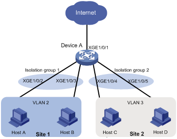
As shown in Figure 1, the company branches Site 1 and Site 2 transfer service traffic in VLAN 2 and VLAN 3. Device A connects to the Internet through Ten-GigabitEthernet 1/0/1.
Configure port isolation on Device A to meet the following requirements:
· All hosts can access the Internet through Device A.
· Host A and Host B are isolated from each other at Layer 2.
· Host C and Host D are isolated from each other at Layer 2.
Software version used
This configuration example was created and verified on S12500-CMW710-R7328P02.
Configuration restrictions and guidelines
When you configure port isolation on the device, follow these restrictions and guidelines:
· By default, Ethernet, VLAN, and aggregate interfaces are shut down. You must use the undo shutdown command to bring them up. The examples assume that all these interfaces are already up.
· Before assigning a port to an isolation group, make sure the isolation group already exists.
· You can assign a port to only one isolation group.
Configuration procedure
# Create VLAN 2 and assign ports Ten-GigabitEthernet 1/0/2 and Ten-GigabitEthernet 1/0/3 to the VLAN.
<DeviceA> system-view
[DeviceA] vlan 2
[DeviceA-vlan2] port ten-gigabitethernet 1/0/2
[DeviceA-vlan2] port ten-gigabitethernet 1/0/3
[DeviceA-vlan2] quit
# Create VLAN 3 and assign ports Ten-GigabitEthernet 1/0/4 and Ten-GigabitEthernet 1/0/5 to the VLAN.
[DeviceA] vlan 3
[DeviceA-vlan3] port ten-gigabitethernet 1/0/4
[DeviceA-vlan3] port ten-gigabitethernet 1/0/5
[DeviceA-vlan3] quit
# Configure port Ten-GigabitEthernet 1/0/1 as a trunk port and assign it to VLAN 2 and VLAN 3.
[DeviceA] interface ten-gigabitethernet 1/0/1
[DeviceA-Ten-GigabitEthernet1/0/1] port link-type trunk
[DeviceA-Ten-GigabitEthernet1/0/1] port trunk permit vlan 2 3
[DeviceA-Ten-GigabitEthernet1/0/1] quit
# Create isolation groups 1 and 2.
[DeviceA] port-isolate group 1
[DeviceA-port-isolate-group1] quit
[DeviceA] port-isolate group 2
[DeviceA-port-isolate-group2] quit
# Assign ports Ten-GigabitEthernet 1/0/2 and Ten-GigabitEthernet 1/0/3 to isolation group 1.
[DeviceA] interface ten-gigabitethernet 1/0/2
[DeviceA-Ten-GigabitEthernet1/0/2] port-isolate enable group 1
[DeviceA-Ten-GigabitEthernet1/0/2] quit
[DeviceA] interface ten-gigabitethernet 1/0/3
[DeviceA-Ten-GigabitEthernet1/0/3] port-isolate enable group 1
[DeviceA-Ten-GigabitEthernet1/0/3] quit
# Assign ports Ten-GigabitEthernet 1/0/4 and Ten-GigabitEthernet 1/0/5 to isolation group 2.
[DeviceA] interface ten-gigabitethernet 1/0/4
[DeviceA-Ten-GigabitEthernet1/0/4] port-isolate enable group 2
[DeviceA-Ten-GigabitEthernet1/0/4] quit
[DeviceA] interface ten-gigabitethernet 1/0/5
[DeviceA-Ten-GigabitEthernet1/0/5] port-isolate enable group 2
[DeviceA-Ten-GigabitEthernet1/0/5] quit
Verifying the configuration
# Display information about all isolation groups.
[DeviceA] display port-isolate group
Port isolation group information:
Group ID: 1
Group members:
Ten-GigabitEthernet1/0/2
Ten-GigabitEthernet1/0/3
Group ID: 2
Group members:
Ten-GigabitEthernet1/0/4
Ten-GigabitEthernet1/0/5
The output shows that:
· Ports Ten-GigabitEthernet 1/0/2 and Ten-GigabitEthernet 1/0/3 are in isolation group 1. As a result, Host A and Host B are isolated from each other at Layer 2.
· Ports Ten-GigabitEthernet 1/0/4 and Ten-GigabitEthernet 1/0/4 are in isolation group 2. As a result, Host C and Host D are isolated from each other at Layer 2.
Configuration files
port-isolate group 1
port-isolate group 2
#
vlan 2 to 3
#
interface Ten-GigabitEthernet1/0/1
port link-mode bridge
port link-type trunk
port trunk permit vlan 1 to 3
#
interface Ten-GigabitEthernet1/0/2
port link-mode bridge
port access vlan 2
port-isolate enable group 1
#
interface Ten-GigabitEthernet1/0/3
port link-mode bridge
port access vlan 2
port-isolate enable group 1
#
interface Ten-GigabitEthernet1/0/4
port link-mode bridge
port access vlan 3
port-isolate enable group 2
#
interface Ten-GigabitEthernet1/0/5
port link-mode bridge
port access vlan 3
port-isolate enable group 2
#
Example: Configuring port isolation with community VLANs
Network requirements
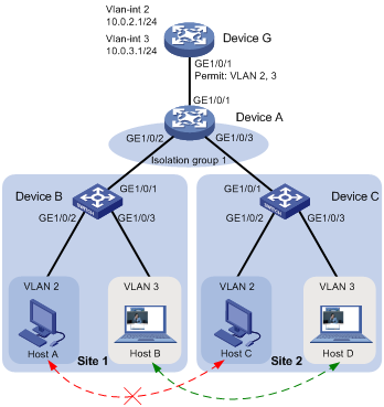
As shown in Figure 2, the company branches Site 1 and Site 2 transfer service traffic in VLAN 2 and VLAN 3. Device G is the gateway that connects to the Internet.
Configure the devices to meet the following requirements:
· Host B can communicate with Host D in VLAN 3.
· Host A and Host C are isolated from each other at Layer 2.
· All hosts can access the Internet through the gateway Device G.
Requirement analysis
To allow Host B and Host D in VLAN 3 to communicate with each other while isolating Host A from Host C in VLAN 2, perform the following tasks on Device A:
1. Assign ports Gigabitethernet 1/0/2 and Gigabitethernet 1/0/3 to isolation group 1.
2. Specify VLAN 3 as the community VLAN in isolation group 1.
Software version used
This configuration example was created and verified on S12500-CMW710-R7328P02.
Configuration restrictions and guidelines
Only devices in standalone mode or in IRF mode with enhanced IRF disabled support community VLANs.
Configuration procedure
1. Configure Device A:
# Create VLAN 2 and VLAN 3.
<DeviceA> system-view
[DeviceA] vlan 2 to 3
# Configure ports Gigabitethernet 1/0/1 through GigabitEthernet 1/0/3 as trunk ports, and assign them to VLAN 2 and VLAN 3.
[DeviceA] interface range gigabitethernet 1/0/1 to gigabitethernet 1/0/3
[DeviceA-if-range] port link-mode bridge
[DeviceA-if-range] port link-type trunk
[DeviceA-if-range] port trunk permit vlan 2 3
[DeviceA-if-range] undo shutdown
[DeviceA-if-range] quit
# Create isolation group 1, and then specify VLAN 3 as a community VLAN in the isolation group.
[DeviceA] port-isolate group 1
[DeviceA-port-isolate-group1] community-vlan vlan 3
[DeviceA-port-isolate-group1] quit
# Assign ports GigabitEthernet 1/0/2 and GigabitEthernet 1/0/3 to isolation group 1.
[DeviceA] interface range gigabitethernet 1/0/2 to gigabitethernet 1/0/3
[DeviceA-if-range] port-isolate enable group 1
[DeviceA-if-range] quit
2. Configure Device B:
# Create VLANs 2 and 3.
<DeviceB> system-view
[DeviceB] vlan 2 to 3
# Assign ports GigabitEthernet 1/0/2 and GigabitEthernet 1/0/3 to VLAN 2 and VLAN 3, respectively.
[DeviceB] interface gigabitethernet 1/0/2
[DeviceB-GigabitEthernet1/0/2] port link-mode bridge
[DeviceB-GigabitEthernet1/0/2] port access vlan 2
[DeviceB-GigabitEthernet1/0/2] undo shutdown
[DeviceB-GigabitEthernet1/0/2] quit
[DeviceB] interface gigabitethernet 1/0/3
[DeviceB-GigabitEthernet1/0/3] port link-mode bridge
[DeviceB-GigabitEthernet1/0/3] port access vlan 3
[DeviceB-GigabitEthernet1/0/3] undo shutdown
[DeviceB-GigabitEthernet1/0/3] quit
# Configure the port that connects to Device A as a trunk port, and assign it to VLAN 2 and VLAN 3.
[DeviceB] interface gigabitethernet 1/0/1
[DeviceB-GigabitEthernet1/0/1] port link-mode bridge
[DeviceB-GigabitEthernet1/0/1] port link-type trunk
[DeviceB-GigabitEthernet1/0/1] port trunk permit vlan 2 3
[DeviceB-GigabitEthernet1/0/1] undo shutdown
[DeviceB-GigabitEthernet1/0/1] quit
3. Configure Device C in the same way Device B is configured. (Details not shown.)
4. Configure Device G:
# Create VLANs 2 and 3.
<DeviceG> system-view
[DeviceG] vlan 2 to 3
# Configure the port that connects to Device A as a trunk port and assign it to VLAN 2 and VLAN 3.
[DeviceG] interface gigabitethernet 1/0/1
[DeviceG-GigabitEthernet1/0/1] port link-mode bridge
[DeviceG-GigabitEthernet1/0/1] port link-type trunk
[DeviceG-GigabitEthernet1/0/1] port trunk permit vlan 2 3
[DeviceG-GigabitEthernet1/0/1] undo shutdown
[DeviceG-GigabitEthernet1/0/1] quit
# Configure IP addresses for VLAN-interface 2 and VLAN-interface 3.
[DeviceG] interface vlan-interface 2
[DeviceG-Vlan-interface2] ip address 10.0.2.1 24
[DeviceG-Vlan-interface2] undo shutdown
[DeviceG-Vlan-interface2] quit
[DeviceG] interface vlan-interface 3
[DeviceG-Vlan-interface3] ip address 10.0.3.1 24
[DeviceG-Vlan-interface3] undo shutdown
[DeviceG-Vlan-interface3] quit
Verifying the configuration
1. Verify the configuration on Device G:
# Ping all hosts. (Details not shown.)
# Verify that Device G has learned the ARP entries for all the hosts in VLAN 2 and VLAN 3.
[DeviceG] display arp
Type: S-Static D-Dynamic O-Openflow M-Multiport I-Invalid
IP address MAC address VLAN Interface Aging Type
10.0.2.2 d485-64a1-7e4a 2 GE1/0/1 19 D
10.0.2.3 7446-a0aa-7774 2 GE1/0/1 19 D
10.0.3.2 6805-ca05-39ae 3 GE1/0/1 20 D
10.0.3.3 6805-ca05-414e 3 GE1/0/1 20 D
2. On Device A, display information about isolation group 1.
[DeviceA] display port-isolate group 1
Port isolation group information:
Group ID: 1
Group members:
GigabitEthernet1/0/2 GigabitEthernet1/0/3
Community VLAN ID: 3
The output shows that:
¡ GigabitEthernet 1/0/2 and GigabitEthernet 1/0/3 are in isolation group 1. As a result, Host A and Host C are isolated from each other.
¡ VLAN 3 is a community VLAN in isolation group 1, indicating that Host B and Host D can communicate with each other.
Configuration files
· Device A:
#
vlan 1
#
vlan 2 to 3
#
port-isolate group 1
community-vlan vlan 3
#
interface GigabitEthernet1/0/1
port link-mode bridge
port link-type trunk
port trunk permit vlan 1 to 3
#
interface GigabitEthernet1/0/2
port link-mode bridge
port link-type trunk
port trunk permit vlan 1 to 3
port-isolate enable group 1
#
interface GigabitEthernet1/0/3
port link-mode bridge
port link-type trunk
port trunk permit vlan 1 to 3
port-isolate enable group 1
#
· Device B and Device C:
#
vlan 1
#
vlan 2 to 3
#
interface GigabitEthernet1/0/1
port link-mode bridge
port link-type trunk
port trunk permit vlan 1 to 3
#
interface GigabitEthernet1/0/2
port link-mode bridge
port access vlan 2
#
interface GigabitEthernet1/0/3
port link-mode bridge
port access vlan 3
#
· Device G:
#
vlan 1
#
vlan 2 to 3
#
interface Vlan-interface2
ip address 10.0.2.1 255.255.255.0
#
interface Vlan-interface3
ip address 10.0.3.1 255.255.255.0
#
interface GigabitEthernet1/0/1
port link-mode bridge
port link-type trunk
port trunk permit vlan 1 to 3
#
Related documentation
· H3C S12500 Routing Switch Series Layer 2—LAN Switching Configuration Guide-Release 7328
· H3C S12500 Routing Switch Series Layer 2—LAN Switching Command Reference-Release 7328