- Table of Contents
- Related Documents
-
| Title | Size | Download |
|---|---|---|
| 00-H3C S12500 Ethernet Link Aggregation Configuration Examples | 188.08 KB |
General configuration restrictions and guidelines
Example: Configuring Layer 2 link aggregation
Configuration restrictions and guidelines
Example: Configuring Layer 2 link aggregation in IRF mode·
Configuration restrictions and guidelines
Example: Configuring Layer 3 link aggregation
Configuration restrictions and guidelines
Introduction
This document provides Ethernet link aggregation configuration examples.
Prerequisites
The configuration examples in this document were created and verified in a lab environment, and all the devices were started with the factory default configuration. When you are working on a live network, make sure you understand the potential impact of every command on your network.
This document assumes that you have basic knowledge of Ethernet link aggregation.
General configuration restrictions and guidelines
You cannot create Layer 3 Ethernet interfaces or subinterfaces, or Layer 3 aggregate interfaces or subinterfaces in the following cases:
· The system is operating in standard mode. For more information about device's operating modes, see H3C S12500 Routing Switch Series Fundamentals Configuration Guide.
· The device is operating in IRF mode and the enhanced IRF mode is enabled. For more information about IRF and the enhanced IRF mode, see H3C S12500 Routing Switch Series Virtual Technologies Configuration Guide.
Example: Configuring Layer 2 link aggregation
Network requirements
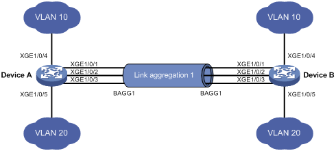
As shown in Figure 1, both Device A and Device B forward traffic from VLAN 10 and VLAN 20.
Configure link aggregation on Device A and Device B to meet the following requirements:
· VLAN 10 on Device A can communicate with VLAN 10 on Device B.
· VLAN 20 on Device A can communicate with VLAN 20 on Device B.
Requirements analysis
To enable traffic from VLAN 10 and VLAN 20 to pass through Layer 2 aggregate interface Bridge-aggregation 1, perform the following tasks:
· Configure Layer 2 aggregate interface Bridge-aggregation 1 as a trunk port.
· Assign the aggregate interface to VLAN 10 and VLAN 20.
Software version used
This configuration example was created and verified on S12500-CMW710-R7328P02.
Configuration restrictions and guidelines
When you configure Layer 2 link aggregation, follow these restrictions and guidelines:
· By default, Ethernet, VLAN, and aggregate interfaces are shut down. You must use the undo shutdown command to bring them up. The examples assume that all these interfaces are already up.
· When you assign a port to an aggregation group, the recommended configuration procedure is as follows:
a. Use the display this command in interface view to check the following attribute configurations of the port:
- Port isolation.
- QinQ.
- VLAN.
- VLAN mapping.
b. If any of the above configurations exist, use the undo forms of the corresponding commands to remove these configurations. This enables the port to use the default attribute configurations.
c. Assign the port to the aggregation group.
· In a static aggregation group, the Selected state of a port is not affected by whether the peer port is added to an aggregation group and is Selected. As a result, the Selected state of a port might be different from the Selected state of the peer port. When both ends support static aggregation and dynamic aggregation, H3C recommends that you use dynamic aggregation.
· You cannot assign a port to a Layer 2 aggregation group when MAC authentication, port security mode, or 802.1X is configured or enabled on the port.
Configuration procedures
1. Configure Device A:
# Create VLAN 10, and assign port Ten-GigabitEthernet 1/0/4 to VLAN 10.
<DeviceA> system-view
[DeviceA] vlan 10
[DeviceA-vlan10] port ten-gigabitethernet 1/0/4
[DeviceA-vlan10] quit
# Create VLAN 20, and assign port Ten-GigabitEthernet 1/0/5 to VLAN 20.
[DeviceA] vlan 20
[DeviceA-vlan20] port ten-gigabitethernet 1/0/5
[DeviceA-vlan20] quit
# Create Layer 2 aggregate interface Bridge-aggregation 1. Use one of the following methods as needed.
? Use the static aggregation mode to create Layer 2 aggregate interface Bridge-aggregation 1.
[DeviceA] interface bridge-aggregation 1
[DeviceA-Bridge-Aggregation1] quit
? Use the dynamic aggregation mode to create Layer 2 aggregate interface Bridge-aggregation 1.
[DeviceA] interface bridge-aggregation 1
[DeviceA-Bridge-Aggregation1] link-aggregation mode dynamic
[DeviceA-Bridge-Aggregation1] quit
# Assign ports Ten-GigabitEthernet 1/0/1 through Ten-GigabitEthernet 1/0/3 to aggregation group 1.
[DeviceA] interface ten-gigabitethernet 1/0/1
[DeviceA-Ten-GigabitEthernet1/0/1] port link-aggregation group 1
[DeviceA-Ten-GigabitEthernet1/0/1] quit
[DeviceA] interface ten-gigabitethernet 1/0/2
[DeviceA-Ten-GigabitEthernet1/0/2] port link-aggregation group 1
[DeviceA-Ten-GigabitEthernet1/0/2] quit
[DeviceA] interface ten-gigabitethernet 1/0/3
[DeviceA-Ten-GigabitEthernet1/0/3] port link-aggregation group 1
[DeviceA-Ten-GigabitEthernet1/0/3] quit
# Configure Layer 2 aggregate interface Bridge-aggregation 1 as a trunk port.
[DeviceA] interface bridge-aggregation 1
[DeviceA-Bridge-Aggregation1] port link-type trunk
Configuring Ten-GigabitEthernet1/0/1 done.
Configuring Ten-GigabitEthernet1/0/2 done.
Configuring Ten-GigabitEthernet1/0/3 done.
# Assign the aggregate interface to VLANs 10 and 20.
[DeviceA-Bridge-Aggregation1] port trunk permit vlan 10 20
Configuring Ten-GigabitEthernet1/0/1 done.
Configuring Ten-GigabitEthernet1/0/2 done.
Configuring Ten-GigabitEthernet1/0/3 done.
[DeviceA-Bridge-Aggregation1] quit
2. Configure Device B in the same way Device A is configured. (Details not shown.)
Verifying the configuration
# Display detailed information about the link aggregation groups on Device A.
· Link aggregation configuration information when the static aggregation mode is used:
[DeviceA] display link-aggregation verbose
Loadsharing Type: Shar -- Loadsharing, NonS -- Non-Loadsharing
Port Status: S -- Selected, U -- Unselected, I -- Individual
Flags: A -- LACP_Activity, B -- LACP_Timeout, C -- Aggregation,
D -- Synchronization, E -- Collecting, F -- Distributing,
G -- Defaulted, H -- Expired
Aggregation Interface: Bridge-Aggregation1
Aggregation Mode: Static
Loadsharing Type: Shar
Port Status Priority Oper-Key
--------------------------------------------------------------------------------
XGE1/0/1 S 32768 1
XGE1/0/2 S 32768 1
XGE1/0/3 S 32768 1
The output shows that all member ports in the local aggregation group are in the Selected state. The Selected states of the local member ports are not affected by the Selected states of the peer member ports.
· Link aggregation configuration information when the dynamic aggregation mode is used:
[DeviceA] display link-aggregation verbose
Loadsharing Type: Shar -- Loadsharing, NonS -- Non-Loadsharing
Port Status: S -- Selected, U -- Unselected, I -- Individual
Flags: A -- LACP_Activity, B -- LACP_Timeout, C -- Aggregation,
D -- Synchronization, E -- Collecting, F -- Distributing,
G -- Defaulted, H -- Expired
Aggregation Interface: Bridge-Aggregation11
Aggregation Mode: Dynamic
Loadsharing Type: Shar
System ID: 0x8000, 000f-e234-5678
Local:
Port Status Priority Oper-Key Flag
--------------------------------------------------------------------------------
XGE1/0/1 S 32768 1 {ACDEF}
XGE1/0/2 S 32768 1 {ACDEF}
XGE1/0/3 S 32768 1 {ACDEF}
Remote:
Actor Partner Priority Oper-Key SystemID Flag
--------------------------------------------------------------------------------
XGE1/0/1 14 32768 1 0x8000, 0000-fc00-7506 {ACDEF}
XGE1/0/2 15 32768 1 0x8000, 0000-fc00-7506 {ACDEF}
XGE1/0/3 16 32768 1 0x8000, 0000-fc00-7506 {ACDEF}
The output shows that the local member ports and the corresponding peer member ports are all Selected. In the dynamic link aggregation mode, each local member port and its peer member port have the same Selected state through exchanging LACPDUs. The user data traffic can be correctly forwarded.
Configuration files
· Device A:
#
vlan 10
#
interface Ten-GigabitEthernet1/0/4
port link-mode bridge
port access vlan 10
#
vlan 20
#
interface Ten-GigabitEthernet1/0/5
port link-mode bridge
port access vlan 20
? In the static aggregation mode:
#
interface Bridge-Aggregation1
port link-type trunk
port trunk permit vlan 10 20
? In the dynamic aggregation mode:
#
interface Bridge-Aggregation1
port link-type trunk
port trunk permit vlan 10 20
link-aggregation mode dynamic
#
interface Ten-GigabitEthernet1/0/1
port link-mode bridge
port link-type trunk
port trunk permit vlan 10 20
port link-aggregation group 1
#
interface Ten-GigabitEthernet1/0/2
port link-mode bridge
port link-type trunk
port trunk permit vlan 10 20
port link-aggregation group 1
#
interface Ten-GigabitEthernet1/0/3
port link-mode bridge
port link-type trunk
port trunk permit vlan 10 20
port link-aggregation group 1
#
· Device B:
The configuration file on Device B is the same as the configuration file on Device A.
Example: Configuring Layer 2 link aggregation in IRF mode
Network requirements
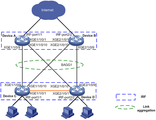
On the network as shown in Figure 2, perform the following tasks:
· Set up a two-chassis IRF fabric at the access layer and a two-chassis IRF fabric at the distribution layer of the enterprise network.
· Configure link aggregation to improve the reliability of the links between the access-layer and distribution-layer IRF fabrics and implement load sharing.
· Run LACP MAD on the two IRF fabrics to detect IRF split.
Software version used
This configuration example was created and verified on S12500-CMW710-R7328P02.
Configuration restrictions and guidelines
When you configure Layer 2 link aggregation in IRF mode, follow these restrictions and guidelines:
· By default, Ethernet, VLAN, and aggregate interfaces are shut down. You must use the undo shutdown command to bring them up. The examples assume that all these interfaces are already up.
· IRF physical ports must be set to the bridge mode.
· When you bind physical ports to an IRF port, you must set all the physical ports to operate in either normal or enhanced mode.
· The physical ports of two connected IRF ports must operate in the same mode: normal or enhanced. For more information about the binding mode of the IRF physical ports, see Virtual technologies Configuration Guide.
· When you assign a port to an aggregation group, the recommended configuration procedure is as follows:
a. Use the display this command in interface view to check the following attribute configurations of the port:
- Port isolation.
- QinQ.
- VLAN.
- VLAN mapping.
b. If any of the above configurations exist, use the undo forms of the corresponding commands to remove these configurations. This enables the port to use the default attribute configurations.
c. Assign the port to the aggregation group.
· In a static aggregation group, the Selected state of a port is not affected by whether the peer port is added to an aggregation group and is Selected. As a result, the Selected state of a port might be different from the Selected state of the peer port. When both ends support static aggregation and dynamic aggregation, H3C recommends that you use dynamic aggregation.
· You cannot assign a port to a Layer 2 aggregation group when MAC authentication, port security mode, or 802.1X is configured or enabled on the port.
Configuration procedures
1. Configure IRF on Device A:
# Assign member ID 1 to Device A.
[DeviceA] irf member 1
# Bind Ten-GigabitEthernet 1/0/1 to IRF port 1.
[DeviceA] irf-port 1
[DeviceA-irf-port1] port group interface ten-gigabitethernet 1/0/1
[DeviceA-irf-port1] quit
# Save the configuration
[DeviceA] quit
<DeviceA> save
# Enable IRF mode.
<DeviceA> system-view
[DeviceA] chassis convert mode irf
The device will switch to IRF mode and reboot.
You are recommended to save the current running configuration and specify the configuration file for the next startup. Continue? [Y/N]:y
Do you want to convert the content of the next startup configuration file flash:/startup.cfg to make it available in IRF mode? [Y/N]:y
Please wait...
Saving the converted configuration file to the main board succeeded.
Slot 1:
Saving the converted configuration file succeeded.
Now rebooting, please wait...
After the reboot, Device A forms a one-chassis IRF fabric. The interface number of Ten-GigabitEthernet 1/0/1 changes to Ten-GigabitEthernet 1/1/0/1.
2. Configure IRF on Device B:
# Assign member ID 2 to Device B.
<DeviceB> system-view
[DeviceB] irf member 2
# Bind Ten-Gigabitethernet 1/0/1 to IRF port 2.
[Sysname] irf-port 2
[DeviceB-irf-port2] port group interface ten-gigabitethernet 1/0/1
[DeviceB-irf-port2] quit
# Save the configuration.
[DeviceB] quit
<DeviceB> save
# Connect the Device A and Device B as shown in Figure 2.
# Enable IRF mode.
<DeviceB> system-view
[DeviceB] chassis convert mode irf
The device will switch to IRF mode and reboot.
You are recommended to save the current running configuration and specify the configuration file for the next startup. Continue? [Y/N]:y
Do you want to convert the content of the next startup configuration file flash:/startup.cfg to make it available in IRF mode? [Y/N]:y
Please wait...
Saving the converted configuration file to the main board succeeded.
Slot 1:
Saving the converted configuration file succeeded.
Now rebooting, please wait...
After the reboot, Device B forms a two-chassis IRF fabric with Device A. The interface number of Ten-GigabitEthernet 1/0/1 changes to Ten-GigabitEthernet 2/1/0/1.
3. Configure a Layer 2 aggregation group on Device A:
# Create Layer 2 aggregate interface Bridge-Aggregation 1, and configure the link aggregation mode as dynamic.
[DeviceA] interface bridge-aggregation 1
[DeviceA-Bridge-Aggregation1] link-aggregation mode dynamic
# Configure Layer 2 aggregation group 1 to load share packets based on source IP addresses.
[DeviceA-Bridge-Aggregation1] link-aggregation load-sharing mode source-ip
[DeviceA-Bridge-Aggregation1] quit
# Assign ports Ten-GigabitEthernet 1/1/0/9, Ten-GigabitEthernet 1/1/0/10, Ten-GigabitEthernet 2/1/0/9, and Ten-GigabitEthernet 2/1/0/10 to link aggregation group 1.
[DeviceA] interface range ten-gigabitethernet 1/1/0/9 to ten-gigabitethernet 1/1/0/10
ten-gigabitethernet 2/1/0/9 to ten-gigabitethernet 2/1/0/10
[DeviceA-if-range] port link-aggregation group 1
[DeviceA-if-range] quit
[DeviceA]
4. Configure LACP MAD on the IRF fabric:
# Set the domain ID of the IRF fabric to 1.
# Enable LACP MAD on Bridge-Aggregation 1.
[DeviceA] interface Bridge-Aggregation 1
[DeviceA-Bridge-Aggregation1] mad enable
You need to assign a domain ID (range: 0-4294967295)
[Current domain is: 1]:
The assigned domain ID is: 1
MAD LACP only enable on dynamic aggregation interface.
5. Configure IRF on Device C in the same way IRF is configured on Device A. (Details not shown.)
6. Configure IRF on Device D in the same way IRF is configured on Device B. (Details not shown.)
Device C and Device D perform master election, and the one that has lost the election reboots to form an IRF fabric with the master. In this example, Device C reboots.
7. Configure a Layer 2 dynamic aggregation group Bridge-Aggregation 1 on Device C in the same way Bridge-Aggregation 1 is configured on Device A. (Details not shown.)
8. Configure LACP MAD on the IRF fabric:
# Set the domain ID of the IRF fabric to 2.
<DeviceC> system-view
[DeviceC] irf domain 2
# Enable LACP MAD on Bridge-Aggregation 1.
[DeviceC] interface Bridge-Aggregation 1
[DeviceC-Bridge-Aggregation1] mad enable
You need to assign a domain ID (range: 0-4294967295)
[Current domain is: 2]:
The assigned domain ID is: 2
MAD LACP only enable on dynamic aggregation interface.
Verifying the configuration
# Display the information about the link aggregation groups on Device A.
[DeviceA] display link-aggregation verbose
Loadsharing Type: Shar -- Loadsharing, NonS -- Non-Loadsharing
Port Status: S -- Selected, U -- Unselected, I -- Individual
Flags: A -- LACP_Activity, B -- LACP_Timeout, C -- Aggregation,
D -- Synchronization, E -- Collecting, F -- Distributing,
G -- Defaulted, H -- Expired
Aggregate Interface: Bridge-Aggregation1
Aggregation Mode: Dynamic
Loadsharing Type: Shar
System ID: 0x8000, 00a0-fc00-5800
Local:
Port Status Priority Oper-Key Flag
--------------------------------------------------------------------------------
XGE1/1/0/9 S 32768 1 {ACDEF}
XGE1/1/0/10 S 32768 1 {ACDEF}
XGE2/1/0/9 S 32768 1 {ACDEF}
XGE2/1/0/10 s 32768 1 {ACDEF}
Remote:
Actor Partner Priority Oper-Key SystemID Flag
--------------------------------------------------------------------------------
XGE1/1/0/9 139 32768 1 0x8000, 0cda-414a-859b {ACDEF}
XGE1/1/0/10 205 32768 1 0x8000, 0cda-414a-859b {ACDEF}
XGE2/1/0/9 204 32768 1 0x8000, 0cda-414a-859b {ACDEF}
XGE2/1/0/10 138 32768 1 0x8000, 0cda-414a-859b {ACDEF}
The output shows that the local member ports and the corresponding peer member ports are all Selected. In the dynamic link aggregation mode, each local member port and its peer member port have the same Selected state through exchanging LACPDUs. The user data traffic can be correctly forwarded.
# Display the load sharing mode of Layer 2 aggregation group 1 on Device A.
[DeviceA] display link-aggregation load-sharing mode interface Bridge-Aggregation 1
Bridge-Aggregation1 Load-Sharing Mode:
source-ip address
The output shows that Layer 2 aggregation group 1 load shares packets based on source IP addresses.
# Shut down physical IRF port Ten-GigabitEthernet 2/1/0/1 on Device B.
A log message appears on Device A.
[DeviceA]%Jan 1 03:12:43:397 2011 Transit STM/3/STM_LINK_STATUS_DOWN: IRF port 2 is down.
%Jan 1 03:12:43:410 2011 Transit DEV/3/BOARD_REMOVED: Board is removed from Slo
t 1, type is MAIN_BOARD_TYPE_52QF.
%Jan 1 03:12:44:385 2011 Transit IFNET/3/PHY_UPDOWN: Ten-GigabitEthernet2/1/0/1
link status is down.
%Jan 1 03:12:44:386 2011 Transit IFNET/5/LINK_UPDOWN: Line protocol on the inte
rface Ten-GigabitEthernet2/1/0/1 is down.
The output shows that IRF split occurs on the distribution layer because Ten-GigabitEthernet 2/1/0/1 that is bound to IRF port 2/2 is physically down.
Configuration files
· Device A:
#
irf domain 1
irf mac-address persistent timer
irf auto-update enable
irf link-delay 0
irf member 1 priority 1
irf member 2 priority 1
#
irf-port 1/1
port group interface Ten-GigabitEthernet1/1/0/1 mode enhanced
#
irf-port 2/2
port group interface Ten-GigabitEthernet2/1/0/1 mode enhanced
#
interface Bridge-Aggregation1
link-aggregation mode dynamic
link-aggregation load-sharing mode source-ip
#
interface Ten-GigabitEthernet1/1/0/9
port link-mode bridge
port link-aggregation group 1
#
interface Ten-GigabitEthernet1/1/0/10
port link-mode bridge
port link-aggregation group 1
#
interface Ten-GigabitEthernet2/1/0/9
port link-mode bridge
port link-aggregation group 1
#
interface Ten-GigabitEthernet2/1/0/10
port link-mode bridge
port link-aggregation group 1
#
· Device C:
The configuration file on Device C is similar as the configuration file on Device A.
Example: Configuring Layer 3 link aggregation
Network requirements
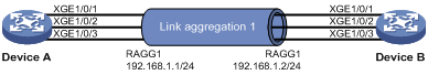
On the network as shown in Figure 3, perform the following tasks:
· Configure a Layer 3 dynamic aggregation group on both Device A and Device B.
· Configure IP addresses and subnet masks for the corresponding Layer 3 aggregate interfaces.
Software version used
This configuration example was created and verified on S12500-CMW710-R7328P02.
Configuration restrictions and guidelines
When you configure Layer 3 link aggregation, follow these restrictions and guidelines:
· By default, Ethernet, VLAN, and aggregate interfaces are shut down. You must use the undo shutdown command to bring them up. The examples assume that all these interfaces are already up.
· In a static aggregation group, the Selected state of a port is not affected by whether the peer port is added to an aggregation group and is Selected. As a result, the Selected state of a port might be different from the Selected state of the peer port. When both ends support static aggregation and dynamic aggregation, H3C recommends that you use dynamic aggregation.
Configuration procedures
# Create Layer 3 aggregate interface Route-Aggregation 1. Use one of the following methods as needed.
? Use the static aggregation mode to create Layer 3 aggregate interface Route-Aggregation 1.
<DeviceA> system-view
[DeviceA] interface route-aggregation 1
? Use the dynamic aggregation mode to create Layer 3 aggregate interface Route-Aggregation 1.
[DeviceA] interface route-aggregation 1
[DeviceA-Route-Aggregation1] link-aggregation mode dynamic
# Configure an IP address and subnet mask for Layer 3 aggregate interface Route-Aggregation 1.
[DeviceA-Route-Aggregation1] ip address 192.168.1.1 24
[DeviceA-Route-Aggregation1] quit
# Assign ports Ten-GigabitEthernet 1/0/1 through Ten-GigabitEthernet 1/0/3 to aggregation group 1.
[DeviceA] interface range ten-gigabitethernet 1/0/1 to ten-gigabitethernet 1/0/3
[DeviceA-if-range] port link-aggregation group 1
2. Configure Device B in the same way Device A is configured. (Details not shown.)
Verifying the configuration
# Display detailed information about the link aggregation groups on Device A.
· Link aggregation configuration information when the static aggregation mode is used:
[DeviceA] display link-aggregation verbose
Loadsharing Type: Shar -- Loadsharing, NonS -- Non-Loadsharing
Port Status: S -- Selected, U -- Unselected
Flags: A -- LACP_Activity, B -- LACP_Timeout, C -- Aggregation,
D -- Synchronization, E -- Collecting, F -- Distributing,
G -- Defaulted, H -- Expired
Aggregate Interface: Route-Aggregation1
Aggregation Mode: Static
Loadsharing Type: Shar
Port Status Priority Oper-Key
--------------------------------------------------------------------------------
XGE1/0/1 S 32768 1
XGE1/0/2 S 32768 1
XGE1/0/3 S 32768 1
The output shows that all member ports in the local aggregation group are in Selected state. The Selected states of the local member ports are not affected by the Selected states of the peer member ports.
· Link aggregation configuration information when the dynamic aggregation mode is used:
[DeviceA] display link-aggregation verbose
Loadsharing Type: Shar -- Loadsharing, NonS -- Non-Loadsharing
Port Status: S -- Selected, U -- Unselected
Flags: A -- LACP_Activity, B -- LACP_Timeout, C -- Aggregation,
D -- Synchronization, E -- Collecting, F -- Distributing,
G -- Defaulted, H -- Expired
Aggregate Interface: Route-Aggregation1
Aggregation Mode: Dynamic
Loadsharing Type: Shar
System ID: 0x8000, 000f-e267-6c6a
Local:
Port Status Priority Oper-Key Flag
--------------------------------------------------------------------------------
XGE1/0/1 S 32768 1 {ACDEF}
XGE1/0/2 S 32768 1 {ACDEF}
XGE1/0/3 S 32768 1 {ACDEF}
Remote:
Actor Partner Priority Oper-Key SystemID Flag
--------------------------------------------------------------------------------
XGE1/0/1 1 32768 1 0x8000, 000f-e267-57ad {ACDEF}
XGE1/0/2 2 32768 1 0x8000, 000f-e267-57ad {ACDEF}
XGE1/0/3 3 32768 1 0x8000, 000f-e267-57ad {ACDEF}
The output shows that the local member ports and the corresponding peer member ports are all Selected. In the dynamic link aggregation mode, each local member port and its peer member port have the same Selected state through exchanging LACPDUs. The user data traffic can be correctly forwarded.
Configuration files
· Device A:
#
? In the static aggregation mode:
#
interface route-aggregation1
ip address 192.168.1.1 255.255.255.0
#
? In the dynamic aggregation mode:
#
interface route-aggregation1
ip address 192.168.1.1 255.255.255.0
link-aggregation mode dynamic
#
interface Ten-GigabitEthernet1/0/1
port link-mode route
port link-aggregation group 1
#
interface Ten-GigabitEthernet1/0/2
port link-mode route
port link-aggregation group 1
#
interface Ten-GigabitEthernet1/0/3
port link-mode route
port link-aggregation group 1
#
· Device B:
The configuration file on Device B is similar as the configuration file on Device A.
Related documentation
· H3C S12500 Routing Switch Series Layer 2—LAN Switching Configuration Guide-Release 7328
· H3C S12500 Routing Switch Series Layer 2—LAN Switching Command Reference-Release 7328