- Table of Contents
- Related Documents
-
| Title | Size | Download |
|---|---|---|
| 04-Frame Relay Configuration | 227.8 KB |
Contents
Data link connection identifier
Frame relay configuration task list
Configuring DTE side frame relay
Configuring basic DTE side frame relay
Configuring frame relay address mappings
Configuring frame relay local virtual circuit
Configuring frame relay subinterface
Configuring DCE side frame relay
Configuring basic DCE side frame relay
Configuring frame relay address mapping
Configuring frame relay local virtual circuit
Configuring frame relay subinterface
Displaying and maintaining frame relay
Frame relay configuration examples
Connecting LANs through a frame relay network
Connecting LANs through a dedicated line
Configuring multilink frame relay·
Configuring multilink frame relay
Configuring an MFR bundle link
Displaying and maintaining multilink frame relay
Multilink frame relay configuration example
Overview
Frame relay is essentially simplified X.25 WAN technology. It uses statistical multiplexing technology and can establish multiple virtual circuits over a single physical cable to make full use of network bandwidth. Frame relay uses data link connection identifiers (DLCIs) to identify virtual circuits and maintain the status of each virtual circuit with the Local Management Interface (LMI) protocol.
Frame relay interface types
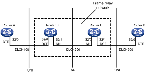
As shown in Figure 1, frame relay enables communication between user devices such as routers and hosts. The user devices are also called “data terminal equipment (DTE)”. They are connected to a frame relay network through the DTE interface. The devices that provide access to the frame relay network for DTEs are called “data communications equipment (DCE)”. A DCE is connected to a DTE with a DCE interface on the user network interface (UNI) side and to a frame relay switch in the frame relay network with a network-to-network interface (NNI) on the NNI side. The switches in the frame relay cloud are interconnected with the NNI.
In actual applications, a DTE interface can connect to only a DCE interface, and an NNI interface can connect to only an NNI interface. On a frame relay switch, the frame relay interface should be an NNI or DCE interface.
As shown in Figure 1, Router B and Router C form a simple frame relay network, to which DTE devices Router A and Router D are attached. You can see that the DTE and DCE are identified on only the UNI interface; a virtual circuit between two DTE devices can be assigned different DLCIs on different segments.
Figure 1 An example frame relay network
Virtual circuit
Virtual circuits fall into permanent virtual circuits (PVCs) and switched virtual circuits (SVCs), depending on how they are set up. Virtual circuits configured manually are called “PVCs”, and those created by protocol negotiation are called “SVCs”, which are automatically created and deleted by the frame relay protocol. The most frequently used in frame relay is the PVC, which is a manually configured virtual circuit.
The PVC status on DTE is completely determined by DCE, and the network determines the PVC status on DCE. If two routers are directly connected, the equipment administrator sets the virtual circuit status of DCE.
Data link connection identifier
A data link connection identifier (DLCI) is a unique number assigned to a virtual circuit endpoint in a frame relay network for the addressing purpose.
A DLCI uniquely identifies a particular virtual circuit on a physical link and has local significance only to that link. A DLCI can be used on different physical ports to address different virtual circuits and a virtual circuit between two DTE devices may be addressed with different DLCIs at the two ends.
Because the virtual circuits in a frame relay network are connection oriented, each DLCI on a physical port is destined for a distinct remote device. DLCIs can be regarded the frame relay addresses of remote devices.
The maximum number of PVCs that can be created on a frame relay interface is 1024. The user configurable DLCIs for the PVCs are in the range 16 to 1007. Other DLCIs are reserved for special purposes. For example, DLCI 0 and DLCI 1023 are reserved for the LMI protocol to transfer control messages.
LMI protocol
Frame relay uses the Local Management Interface (LMI) protocol to set up virtual circuits and maintain their status between DTE and DCE.
The system supports the following LMI standards:
· ITU-T Q.933 Annex A
· ANSI T1.617 Annex D
· Nonstandard LMI (compatible with other vendors)
To communicate properly, the DTE and the DCE must use the same type of LMI.
LMI uses the status inquiry message and the status messages to maintain the link status and PVC status, for example, to advertise new PVCs, detect deleted PVCs, monitor PVC status changes, and verify link integrity. For these purposes, the DTE sends status inquiry messages regularly to the DCE to request for the availability of individual PVCs. On receiving a status inquiry, the DCE responds with a status message that describes the status of each virtual circuit on the physical link.
For a DTE, the status of a PVC is determined by the DCE; as for DCE, by the frame relay network.
Table 1 lists the major parameters ITU-T Q.933 Annex A uses for message exchange. You can configure these parameters to optimize device performance.
Table 1 Parameter description for frame relay protocol
|
Router role |
Parameter description |
Value range |
Default value |
|
DTE |
PVC status enquiry counter (N391) |
1 to 255 |
6 |
|
Error threshold (N392) |
1 to 10 |
3 |
|
|
Event counter (N393) |
1 to 10 |
4 |
|
|
User side polling timer (T391), the value 0 indicates that the LMI protocol is disabled |
0 to 32767 (in seconds) |
10 (in seconds) |
|
|
DCE |
Error threshold (N392) |
1 to 10 |
3 |
|
Event counter (N393) |
1 to 10 |
4 |
|
|
Network side polling timer (T392) |
5 to 30 (in seconds) |
15 (in seconds) |
These parameters are stipulated by Q.933 Appendix A, and their meanings are described in the following sections.
Description on parameters related to DTE
The following parameters are related to DTE:
· N391—Sets the full status polling interval. DTE sends Status-Enquiry messages at a certain interval (determined by T391). Status-Enquiry messages fall into the following types: link integrity verification messages and full link status enquiry messages. N391 defines that the ratio of sent link integrity verification messages to sent full link status enquiry messages equals (N391–1):1.
· N392—Sets the threshold for errors among the observed events.
· N393—Sets the total of observed events.
· T391—Sets the interval for a DTE to send State-Enquiry messages.
A DTE sends Status-Enquiry messages at a certain interval to query the link status. The DCE responds with a Status response message on receiving the message. If the DTE fails to receive any response within a specified period, it will record this error. If the number of errors exceeds a certain error threshold, DTE will regard the physical channel and all virtual circuits unavailable (N392 and N393 together define the error threshold). If the number of errors reaches N392 among the N393 Status-Enquiry messages sent by DTE, DTE will consider that the number of errors has reached the threshold.
|
|
NOTE: Status-Enquiry messages fall into the following types: link integrity verification messages and full link status enquiry messages. The full link status enquiry messages query PVC status in addition to link integrity. |
Description on parameters related to DCE
The following parameters are related to DCE:
· N392 and N393—These two parameters have similar meanings to those related to DTE. However, DCE requires that the fixed time interval for DTE sending a Status-Enquiry message should be determined by T392, and DTE requires that this interval should be determined by T391. If DCE does not receive the Status-Enquiry message from DTE within a period determined by T392, an error recorder is created.
· T392—Sets the time variable, which defines the maximum time that DCE waits for a Status-Enquiry message and should be larger than the value of T391.
Frame relay address mapping
Frame relay address mapping associates the protocol address of a remote router with its frame relay address (local DLCI). Through searching the frame relay address map by protocol address, the upper layer protocol can locate a remote router. Frame relay can bear the IP protocol. When sending an IP packet, the frame relay-enabled router can obtain its next hop address after consulting the routing table, which is inadequate for sending the packet to the correct destination across a frame relay network. To identify the DLCI of the next hop address, the router must search a frame relay address map retaining the associations between remote IP addresses and next hop DLCIs.
A frame relay address map can be manually configured or maintained by Inverse Address Resolution Protocol (InARP).
The following describes how frame relay uses InARP to create an address mapping:
Once a new virtual circuit is created, InARP sends an inverse ARP request over the circuit to request the peer end for its protocol address. This request also conveys the local protocol address. When the peer device receives the request, it creates an address mapping based on the protocol address in the request and responds with its protocol address. When the local end receives the response, it creates the address mapping for the peer.
For virtual circuits that have static address mappings, InARP will not be performed regardless of whether the mappings are correct or not. In addition, the inverse ARP request recipient does not create a mapping based on the protocol address in the request if a static entry is already available for the address.
Frame relay configuration task list
Complete the following tasks to configure frame relay:
|
Task |
Remarks |
|
|
Required |
||
|
Required |
||
|
Required |
||
|
Optional |
||
|
Required |
||
|
Required |
||
|
Required |
||
|
Optional |
||
|
Optional |
||
|
|
CAUTION: · Only PIC-ET32G2L sub-cards and POS sub-cards support Frame Relay. · Before switching the link layer protocol of an interface (from PPP/HDLC to Frame Relay or the other way around), manually remove all configurations related to QoS and ACL policies on the interface first. |
Configuring DTE side frame relay
Configuring basic DTE side frame relay
To configure DTE side frame relay:
|
Step |
Command |
Remarks |
|
1. Enter system view. |
system-view |
N/A |
|
2. Enter interface view. |
interface interface-type interface-number |
N/A |
|
3. Configure the interface encapsulation protocol as frame relay. |
link-protocol fr [ ietf | nonstandard ] |
The default link layer protocol of an interface is PPP. When frame relay is configured as the link layer protocol, the encapsulation format is defaulted to IETF. |
|
4. Configure the frame relay interface type as DTE. |
fr interface-type dte |
Optional. The default frame relay interface type is DTE. |
|
5. Configure frame relay LMI protocol type. |
fr lmi type { ansi | nonstandard | q933a } |
Optional. The default frame relay LMI protocol type is q933a. |
|
6. Configure user side N391. |
fr lmi n391dte n391-value |
Optional. The default value is 6. |
|
7. Configure user side N392. |
fr lmi n392dte n392-value |
Optional. The default value is 3. |
|
8. Configure user side N393. |
fr lmi n393dte n393-value |
Optional. The default value is 4. |
|
9. Configure user side T391. |
timer hold seconds |
Optional. The default value is 10 seconds. |
Configuring frame relay address mappings
Overview
Configure frame relay address mappings in one of the following ways:
· Manually creating static mappings between peer IP addresses and local DLCIs.
Use this approach when the network topology is relatively stable and no new users are expected in a certain period of time. Because static mappings do not change, the network connections are stable, and attacks from unknown users are avoided.
· Using InARP to dynamically create mappings between peer IP addresses and local DLCIs.
Use this approach in complicated networks and make sure that the peer router also supports InARP.
Configuring static frame relay address mappings
To configure static frame relay address mappings:
|
Step |
Command |
Remarks |
|
1. Enter system view. |
system-view |
N/A |
|
2. Enter interface view. |
interface interface-type interface-number |
N/A |
|
3. Create a static frame relay address mapping. |
fr map ip ip-address dlci-number [ broadcast | [ ietf | nonstandard ] ] * |
No static frame relay address mappings are configured by default. |
Configuring dynamic frame relay address mapping
To configure dynamic frame relay address mapping:
|
Step |
Command |
Remarks |
|
1. Enter system view. |
system-view |
N/A |
|
2. Enter interface view. |
interface interface-type interface-number |
N/A |
|
3. Enable frame relay InARP for dynamic address mapping. |
fr inarp [ ip [ dlci-number ] ] |
Optional. By default, frame relay InARP is enabled for dynamic address mapping. |
|
|
NOTE: · You do not need to configure DLCIs for PVCs, if static address mappings are configured. · Do not configure static address mapping on a P2P subinterface. A P2P subinterface carries only one PVC. |
Configuring frame relay local virtual circuit
Overview
When the frame relay interface type is DCE, the interface (either a main interface or subinterface) needs to be manually configured with virtual circuits. When the frame relay interface type is DTE, for the main interface, the virtual circuit can be determined by the system according to the peer router or through manual configuration; for a subinterface, the virtual circuits must be manually configured.
A virtual circuit number is unique on a physical interface.
Configuration procedure
To configure frame relay local virtual circuit
|
Step |
Command |
Remarks |
|
1. Enter system view. |
system-view |
N/A |
|
2. Enter interface view. |
interface interface-type interface-number |
N/A |
|
3. Configure a virtual circuit on the interface. |
fr dlci dlci-number |
By default, no virtual circuits are created on interfaces. |
|
|
NOTE: If the DLCI of a PVC is changed on the DCE interface, you can reset both the DCE and DTE interfaces or execute the reset inarp command on both ends to enable the DTE to re-learn the correct address mappings as soon as possible. Before doing that, make sure that no services will be interrupted. |
Configuring frame relay subinterface
Overview
Frame relay offers the following types of interfaces: main interface and subinterface. The subinterface is of logical structure, which can be configured with protocol address and virtual circuit. One physical interface can include multiple subinterfaces, which do not exist physically. However, for the network layer, the subinterface and main interface make no difference and both can be configured with virtual circuits to connect to remote routers.
The subinterface of frame relay falls into the following types: point-to-point (P2P) subinterface and point-to-multipoint (P2MP) subinterface. A P2P subinterface connects a single remote router and a P2MP subinterface connects multiple remote routers. A P2MP subinterface can be configured with multiple virtual circuits, each of which sets up an address map with its connected remote network address to distinguish different connections. Address maps can be set up manually or dynamically set up by InARP.
The methods to configure a virtual circuit and address map for P2P subinterfaces and P2MP subinterfaces are different, as described below.
· P2P subinterface
Because a P2P subinterface has only one peer address, the peer address is implicitly determined when a virtual circuit is configured for the subinterface. As a result, you do not need to configure dynamic or static address mapping for P2P subinterface.
· P2MP subinterface
For a P2MP subinterface, a peer address can be mapped to the local DLCI through static address mapping or InARP which only needs to be configured on the main interface. If static address mapping is required, it is necessary to set up static address map for each virtual circuit.
Configuration procedure
To configure a frame relay subinterface:
|
Step |
Command |
Remarks |
|
1. Enter system view. |
system-view |
N/A |
|
2. Create a subinterface and enter subinterface view. |
interface interface-type interface-number.subnumber [ p2mp | p2p ] |
By default, no frame relay subinterface is created. On creation, the type of a frame relay subinterface is p2mp by default. |
|
3. Configure a virtual circuit on a frame relay subinterface. |
N/A |
|
|
4. Configure address mapping. |
Optional. For a P2MP subinterface, you must set up an address map. |
Configuring DCE side frame relay
Configuring basic DCE side frame relay
To configure DCE side frame relay:
|
Step |
Command |
Remarks |
|
1. Enter system view. |
system-view |
N/A |
|
2. Enter interface view. |
interface interface-type interface-number |
N/A |
|
3. Configure interface encapsulation protocol as frame relay. |
link-protocol fr [ ietf | nonstandard ] |
The link layer protocol for interface encapsulation is PPP by default. When frame relay is configured as the link layer protocol, the encapsulation format is defaulted to IETF. |
|
4. Configure the frame relay interface type to DCE. |
fr interface-type dce |
Optional. The default frame relay interface type is DTE. |
|
5. Configure the frame relay LMI protocol type. |
fr lmi type { ansi | nonstandard | q933a } |
Optional. The default frame relay LMI protocol type is q933a. |
|
6. Configure network side N392. |
fr lmi n392dce n392-value |
Optional. The default value is 3. |
|
7. Configure network side N393. |
fr lmi n393dce n393-value |
Optional. The default value is 4. |
|
8. Configure network side T392. |
fr lmi t392dce t392-value |
Optional. The default value is 15 seconds. |
Configuring frame relay address mapping
See “Configuring frame relay address mappings.”
Configuring frame relay local virtual circuit
See “Configuring frame relay local virtual circuit.”
Configuring frame relay subinterface
See “Configuring frame relay subinterface.”
Enabling the trap function
With the trap function enabled for frame relay, notifications traps are generated for notifying critical events that occur to frame relay. Thus, when events that should be notified occur to frame relay, traps will be sent to the information center. You can configure the information center to output the trap information matches certain criteria to a desired destination (the console for example) for analysis.
To enable the trap function for the frame relay module:
|
Step |
Command |
Remarks |
|
1. Enter system view. |
system-view |
N/A |
|
2. Enable trap for the frame relay module. |
snmp-agent trap enable fr |
Optional. By default, trap is enabled for the frame relay module. |
|
|
NOTE: · For more information about the snmp-agent trap enable fr command, see Network Management and Monitoring Command Reference. · For how to configure the information center, see Network Management and Monitoring Configuration Guide. |
Displaying and maintaining frame relay
|
Task |
Command |
Remarks |
||
|
Display frame relay protocol status on an interface. |
display fr interface [ interface-type { interface-number | interface-number.subnumber } ] [ | { begin | exclude | include } regular-expression ] |
Available in any view |
||
|
Display the mapping table of protocol address and frame relay address. |
display fr map-info [ interface interface-type { interface-number | interface-number.subnumber } ] [ | { begin | exclude | include } regular-expression ] |
Available in any view |
||
|
Display receiving/sending statistics of frame relay LMI type messages. |
display fr lmi-info [ interface interface-type interface-number ] [ | { begin | exclude | include } regular-expression ] |
Available in any view |
||
|
Display incoming and outgoing frame relay data statistics. |
display fr statistics [ interface interface-type interface-number ] [ | { begin | exclude | include } regular-expression ] |
Available in any view |
||
|
Display frame relay permanent virtual circuit table. |
display fr pvc-info [ interface interface-type { interface-number | interface-number.subnumber } ] [ dlci-number ] [ | { begin | exclude | include } regular-expression ] |
Available in any view |
||
|
Display statistics of frame relay InARP messages. |
display fr inarp-info [ interface interface-type interface-number ] [ | { begin | exclude | include } regular-expression ] |
Available in any view |
||
|
Clear all the automatically established frame relay address mappings. |
reset fr inarp |
Available in user view |
||
|
Clear the statistics on an FR PVC. |
reset fr pvc interface serial interface-number [ dlci dlci-number ] |
Available in user view |
||
Frame relay configuration examples
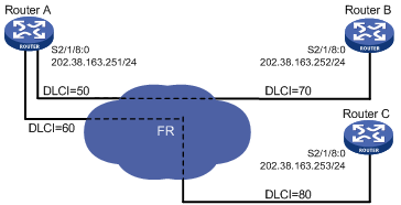
Connecting LANs through a frame relay network
Network requirements
As shown in Figure 2, connect LANs through the public frame relay network. In this implementation, the routers can only work as DTE.
Configuration procedure
1. Configure Router A:
# Assign an IP address to interface Serial 2/1/8:0.
<RouterA> system-view
[RouterA] interface Serial 2/1/8:0
[RouterA-Serial2/1/8:0] ip address 202.38.163.251 255.255.255.0
# Configure interface encapsulation protocol as frame relay.
[RouterA-Serial2/1/8:0] link-protocol fr
[RouterA-Serial2/1/8:0] fr interface-type dte
# If the opposite router supports InARP, configure dynamic address mapping.
[RouterA-Serial2/1/8:0] fr inarp
# Otherwise, configure static address mapping.
[RouterA-Serial2/1/8:0] fr map ip 202.38.163.252 50
[RouterA-Serial2/1/8:0] fr map ip 202.38.163.253 60
2. Configure Router B:
# Assign an IP address.
<RouterB> system-view
[RouterB] interface Serial 2/1/8:0
[RouterB-Serial2/1/8:0] ip address 202.38.163.252 255.255.255.0
# Configure interface encapsulation protocol as frame relay.
[RouterB-Serial2/1/8:0] link-protocol fr
[RouterB-Serial2/1/8:0] fr interface-type dte
# If the opposite router supports InARP, configure dynamic address mapping.
[RouterB-Serial2/1/8:0] fr inarp
# Otherwise, configure static address mapping.
[RouterB-Serial2/1/8:0] fr map ip 202.38.163.251 70
3. Configure Router C:
# Assign an IP address.
<RouterC> system-view
[RouterC] interface Serial 2/1/8:0
[RouterC-Serial2/1/8:0] ip address 202.38.163.253 255.255.255.0
# Configure the interface encapsulation protocol as frame relay.
[RouterC-Serial2/1/8:0] link-protocol fr
[RouterC-Serial2/1/8:0] fr interface-type dte
# If the opposite router supports InARP, configure dynamic address mapping.
[RouterC-Serial2/1/8:0] fr inarp
# Otherwise, configure static address mapping.
[RouterC-Serial2/1/8:0] fr map ip 202.38.163.251 80
Connecting LANs through a dedicated line
Network requirements
As shown in Figure 3, two routers are directly connected through serial interfaces. Router A works in the frame relay DCE mode, and Router B works in the frame relay DTE mode.

Configuration procedure
1. Configure Router A:
# Set the link layer protocol on the interface to frame relay and interface type to DCE.
<RouterA> system-view
[RouterA] interface Serial 2/1/8:0
[RouterA-Serial2/1/8:0] link-protocol fr
[RouterA-Serial2/1/8:0] fr interface-type dce
[RouterA-Serial2/1/8:0] quit
# Configure the IP address of the subinterface and local virtual circuit.
[RouterA] interface Serial 2/1/8:0.1 p2p
[RouterA-Serial2/1/8:0.1] ip address 202.38.13.251 255.255.255.0
[RouterA-Serial2/1/8:0.1] fr dlci 100
2. Configure Router B:
# Set the link layer protocol on the interface to frame relay and interface type to DTE.
<RouterB> system-view
[RouterB] interface Serial 2/1/8:0
[RouterB-Serial2/1/8:0] link-protocol fr
[RouterB-Serial2/1/8:0] quit
# Configure IP address of the subinterface and local virtual circuit.
[RouterB] interface Serial 2/1/8:0.1 p2p
[RouterB-Serial2/1/8:0.1] ip address 202.38.13.252 255.255.255.0
[RouterB-Serial2/1/8:0.1] fr dlci 100
Troubleshooting frame relay
Symptom 1:
The physical layer is in down status.
Solution:
· Check whether the physical line is normal.
· Check whether the remote router runs properly.
Symptom 2:
The physical layer is already up, but the link layer protocol is down.
Solution:
· Make sure that both local router and remote router have been encapsulated with frame relay protocol.
· If two routers are directly connected, check the local router and remote router to make sure that one end is configured as frame relay DTE interface and the other end as frame relay DCE interface.
· Make sure that the LMI protocol type configuration at the two ends is the same.
· If the conditions are satisfied, use the debugging lmi command to enable the monitoring function for the frame relay LMI messages to see whether one Status Request message corresponds to one Status Response message. If not, it indicates the physical layer data is not received/sent correctly. Check the physical layer.
Symptom 3:
The link layer protocol is up, but the remote party cannot be pinged.
Solution:
· Make sure that the routers at both ends have configured (or created) correct address mapping for the peer.
· Make sure that a route to the peer exists if the routers are not in the same subnet segment.
Overview
Multilink frame relay (MFR) is a cost effective bandwidth solution for frame relay users. Based on the FRF.16 protocol of the frame relay forum, it implements the MFR function on DTE/DCE interfaces.
MFR function provides a kind of logical interface, MFR interface. The MFR interface is composed of multiple frame relay physical links bound together, and you can configure subinterfaces for the MFR interface. The MFR interface provides high-speed and broadband links on frame relay networks.
To maximize the bandwidth of bundled interface, bundle physical interfaces of the same rate for the same MFR interface when you configure the MFR interface so as to reduce management cost.
Bundle and bundle link
Bundle and bundle link are two basic concepts related to MFR.
One MFR interface corresponds to one bundle, which may contain multiple bundle links. One bundle link corresponds to one physical interface. A bundle manages its bundle links. The interrelationship between bundle and bundle link is illustrated in Figure 4.
Figure 4 Illustration of bundle and bundle links
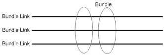
For the actual physical layer, a bundle link is visible. For the actual data link layer, a bundle is visible.
MFR interface and physical interface
An MFR interface is a kind of logic interface. Multiple physical interfaces can be bundled into one MFR interface. One MFR interface corresponds to one bundle and one physical interface corresponds to one bundle link. The configuration on a bundle and bundle links is actually configuration on an MFR interface and physical interfaces.
The function and configuration of the MFR interface is the same with that on the FR interface in common sense. Like the FR interface, the MFR interface supports DTE and DCE interface types as well as QoS queue mechanism. After physical interfaces are bundled into an MFR interface, their original network layer and frame relay link layer parameters become ineffective and they use the parameter settings of the MFR interface instead.
Configuring multilink frame relay
Configuring an MFR bundle
To configure an MFR bundle:
|
Step |
Command |
Remarks |
|
1. Enter system view. |
system-view |
N/A |
|
2. Create an MFR interface and enter MFR interface view. |
interface mfr { interface-number | interface-number.subnumber [ p2mp | p2p ] } |
No MFR interface or subinterface is created by default. On creation, the type of an MFR subinterface is p2mp by default. |
|
3. Configure the MFR bundle identifier. |
mfr bundle-name [ name ] |
Optional. By default, the bundle identifier is MFR + frame relay bundle number. |
|
4. Configure MFR fragmentation. |
mfr fragment |
Optional. Fragmentation is disabled on MFR bundles by default. |
|
5. Configure maximum fragment size for bundle link. |
mfr fragment-size bytes |
Optional. The maximum fragment is of 300 bytes by default. |
|
6. Configure other parameters of the MFR interface. |
See the chapter “Configuring frame relay.” |
Optional. |
Configuring an MFR bundle link
To configure an MFR bundle link:
|
Step |
Command |
Remarks |
|
1. Enter system view. |
system-view |
N/A |
|
2. Enter frame relay interface view. |
interface interface-type interface-number |
N/A |
|
3. Assign the current interface to an MFR interface. |
link-protocol fr mfr interface-number |
An interface is not assigned to any MFR interface by default. |
|
4. Configure the MFR bundle link identifier. |
mfr link-name [ name ] |
Optional. The name of the current interface is used by default. |
|
5. Configure the hello message sending interval for the MFR bundle link. |
mfr timer hello seconds |
Optional. The default setting is 10 seconds. |
|
6. Configure the waiting time before the MFR bundle link resends hello messages. |
mfr timer ack seconds |
Optional. The default setting is 4 seconds. |
|
7. Configure the maximum times that the MFR bundle link can resend hello messages. |
mfr retry number |
Optional. The default setting is 2. |
Displaying and maintaining multilink frame relay
|
Task |
Command |
Remarks |
|
Display configuration and status of an MFR interface. |
display interface mfr [ interface-number | interface-number:subnumber ] [ | { begin | exclude | include } regular-expression ] |
Available in any view |
|
Display configuration and statistics of an MFR bundle and bundle links. |
display mfr [ interface interface-type interface-number | verbose ] [ | { begin | exclude | include } regular-expression ] |
Available in any view |
|
Clear statistics of MFR interfaces. |
reset counters interface [ mfr [ interface-number | interface-number.subnumber ] ] |
Available in user view |
Multilink frame relay configuration example
Network requirements
As shown in Figure 5, use the multilink frame relay protocol to bundle the two serial ports to provide higher bandwidth.
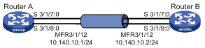
Configuration procedure
1. Configure Router A:
# Create and configure MFR interface MFR 3/1/12.
<RouterA> system-view
[RouterA] interface MFR 3/1/12
[RouterA-MFR3/1/12] ip address 10.140.10.1 255.255.255.0
[RouterA-MFR3/1/12] fr interface-type dte
[RouterA-MFR3/1/12] fr map ip 10.140.10.2 100
[RouterA-MFR3/1/12] quit
# Bundle serial interfaces to MFR 3/1/12.
[RouterA] interface Serial 3/1/7:0
[RouterA-Serial3/1/7:0] link-protocol fr MFR 3/1/12
[RouterA-Serial3/1/7:0] quit
[RouterA] interface Serial 3/1/8:0
[RouterA-Serial3/1/8:0] link-protocol fr MFR 3/1/12
2. Configure Router B:
# Create and configure MFR interface MFR 3/1/12.
<RouterB> system-view
[RouterB] interface MFR 3/1/12
[RouterB-MFR3/1/12] ip address 10.140.10.2 255.255.255.0
[RouterB-MFR3/1/12] fr interface-type dce
[RouterB-MFR3/1/12] fr dlci 100
[RouterB-fr-dlci-MFR3/1/12-100] quit
[RouterB-MFR3/1/12] fr map ip 10.140.10.1 100
[RouterB-MFR3/1/12] quit
# Bundle serial interfaces to MFR 3/1/12.
[RouterB] interface Serial 3/1/7:0
[RouterB-Serial3/1/7:0] link-protocol fr MFR 3/1/12
[RouterB-Serial3/1/7:0] quit
[RouterB] interface Serial 3/1/8:0
[RouterB-Serial3/1/8:0] link-protocol fr MFR 3/1/12