- Table of Contents
- Related Documents
-
| Title | Size | Download |
|---|---|---|
| 02-PPP Configuration | 278.07 KB |
Contents
Configuring PAP authentication
Configuring CHAP authentication
Configuring MS-CHAP or MS-CHAP-V2 authentication
Configuring an MP through an MP-group
Configuring short sequence number header format negotiation
Configuring MP endpoint options
Displaying and maintaining PPP/MP
PPP and MP configuration examples
One-way PAP authentication configuration example
Two-way PAP authentication configuration example
One-way CHAP authentication configuration example
MP binding mode configuration examples
Troubleshooting PPP configuration
A link cannot revert to the up state
A link remains down after IPv6CP negotiation fails
Introduction to PPP and MP
PPP
Point-to-Point Protocol (PPP) is a link layer protocol that carries network layer packets over point-to-point links. It gains popularity because it provides user authentication, supports synchronous/asynchronous communication, and allows for easy extension.
PPP contains a set of protocols, including a link control protocol (LCP), a network control protocol (NCP), and authentication protocols such as Password Authentication Protocol (PAP), Challenge Handshake Authentication Protocol (CHAP), MS-CHAP, and MS-CHAP-V2. Among these protocols,
· The LCP is responsible for establishing, tearing down, and monitoring data links.
· The NCP is used for negotiating the packet format and type of data links.
· PAP, CHAP, MS-CHAP, and MS-CHAP-V2 are for network security.
PAP authentication
PAP is a two-way handshake authentication protocol using plain text passwords. It operates as follows.
1. The requester sends its username and password to the authenticator.
2. The authenticator then checks the local user list to see if the username and password are correct and returns an acknowledgement or negative acknowledge.
Figure 1 PAP Authentication
During PAP authentication, the password is transmitted on the link in plain text. In addition, the supplicant sends the username and the password repeatedly through the established PPP link until the authentication is over. Therefore, PAP is not a secure authentication protocol. It cannot prevent attacks.
CHAP authentication
CHAP is a three-way handshake authentication protocol using cipher text password.
Two types of CHAP authentication exist: one-way CHAP authentication and two-way CHAP authentication. By one-way CHAP authentication, one side of the link acts as the authenticator and the other acts as the supplicant. By two-way authentication, each side serves as both the authenticator and the supplicant. Normally, one-way CHAP authentication is used.
In one-way CHAP authentication, the authenticator may or may not be configured with a username. It is recommended that you configure a username for the authenticator, which makes it easier to identify the authenticator.
If the authenticator is configured with a username, CHAP authentication is performed as follows:
1. The authenticator initiates an authentication by sending a randomly-generated packet (Challenge) to the supplicant. The packet carries the local username with it in addition.
2. When the supplicant receives the authentication request, it searches the local user list for the password of the username carried in the received packet, encrypts the packet using the MD5 algorithm, with the packet ID and the password as the parameters, and then sends the encrypted packet and the local username to the authenticator (Response).
3. The authenticator encrypts the original randomly-generated packet using the MD5 algorithm, with the password of the supplicant it maintains as the parameter, compares the encrypted packet with the one received from the supplicant, and returns an Acknowledge or Not Acknowledge packet depending on the comparison result.
If the authenticator is not configured with a username, the CHAP authentication is performed as follows:
1. The authenticator initiates an authentication by sending a randomly-generated packet (Challenge) to the supplicant.
2. When the supplicant receives the authentication request, it encrypts the packet using the MD5 algorithm, with the packet ID and the default CHAP password as the parameters, and then sends the encrypted packet and its own username to the authenticator (Response).
3. The authenticator encrypts the original randomly-generated packet using the MD5 algorithm, with the password of the supplicant it maintains as the parameter, compares the encrypted packet with the one received from the supplicant, and returns an Acknowledge or Not Acknowledge packet depending on the comparison result.
Figure 2 CHAP Authentication
MS-CHAP authentication
MS-CHAP is a three-way handshake authentication protocol using cipher text password.
Different from CHAP, MS-CHAP is enabled by negotiating CHAP Algorithm 0x80 in LCP option 3. Authentication Protocol, and MS-CHAP provides the authenticator-controlled authentication retry mechanism.
MS-CHAP authentication operates in the following workflow.
1. The authenticator initiates an authentication by sending a randomly-generated packet (Challenge) to the supplicant.
2. When the supplicant receives the authentication request, it encrypts the packet and its own password by using the 0x80 algorithm, and then sends the encrypted packet and its own username to the authenticator (Response).
3. When receiving the Response packet, the authenticator searches the local user list for the password of the username carried in the Response packet, encrypts the packet and the supplicant’s password by using the 0x80 algorithm, with the Challenge packet and the password as the parameters, compares the encrypted packet with the one received from the supplicant, and returns an Acknowledge or Not Acknowledge packet depending on the comparison result.
¡ If the authentication succeeds, the Acknowledge packet carries the greeting information.
¡ If the authentication fails, the Not Acknowledge packet carries errors, retry flag, and new randomly-generated packet (Challenge).
4. When the supplicant receives an Acknowledge packet, the authentication succeeds.
5. When the supplicant receives a Not Acknowledge packet that carries the retry (R) flag set to 1, the supplicant encrypts the Challenge packet and its own password by using the 0x80 algorithm, and sends the encrypted packet and its own username to the authenticator. The authenticator re-authenticates the Response packet. If the R flag in the packet is 0, the authentication fails and the authenticator disconnects from the supplicant. The authenticator allows the supplicant to retry for three times.
MS-CHAP-V2
MS-CHAP-V2 is a three-way handshake authentication protocol using cipher text password.
Different from CHAP, MS-CHAP-V2 is enabled by negotiating CHAP Algorithm 0x81 in LCP option 3, Authentication Protocol, provides mutual authentication between peers by piggybacking a peer challenge on the Response packet and an authenticator response on the Acknowledge packet, and supports the authentication retry and password changing mechanisms.
MS-CHAP-V2 authentication operates in the following workflow.
1. The authenticator initiates an authentication by sending a randomly-generated packet (Challenge) to the supplicant.
2. When the supplicant receives the authentication request, it encrypts the Challenge packet, its own randomly-generated packet (Peer-Challenge), its own username, and password by using the 0x81 algorithm, and then sends the encrypted packet and username to the authenticator (Response).
3. When receiving the Response packet, the authenticator encrypts the supplicant’s Peer-Challenge packet, the Challenge packet, and supplicant’s username and password by using the 0x81 algorithm. The authenticator compares the encrypted packet with the one received from the supplicant, and returns an Acknowledge or Not Acknowledge packet depending on the comparison result.
¡ If the authentication succeeds, the Acknowledge packet carries the encrypted packet from the supplicant for piggybacking authentication. The encrypted packet is generated by using the 0x81 algorithm, with the supplicant’s username and password, the encrypted packet received from the supplicant, the Peer-Challenge packet, and the Challenge packet as the parameters.
¡ If the authentication fails, the Not Acknowledge packet carries error code, retry flag, and new randomly-generated packet (Challenge).
4. When the supplicant receives an Acknowledge packet, it encrypts a packet by using the 0x81 algorithm, with its own username and password, the Challenge packet, Peer-Challenge packet, and the encrypted packet sent to the authenticator as the parameters. The supplicant compares the encrypted packet with the one sent to the authenticator. If they match each other, the authentication succeeds. If not, the link is disconnected.
5. When the supplicant receives a Not Acknowledge packet from the authenticator:
¡ If the error in the packet is due to password expiration, the supplicant encrypts a packet by using the 0x81 algorithm, with a new password, the Challenge packet, Peer-Challenge packet, and its own username as the parameters, and sends the encrypted packet and new password after encryption (change password) to the authenticator. The authenticator re-authenticates the supplicant by using the new password.
¡ If the R flag in the Not Acknowledge packet is 1, the supplicant encrypts a packet by using the 0x81 algorithm, with the Challenge packet, Peer-Challenge packet, its own username and password as the parameters, and sends the encrypted packet and its own username to the authenticator. The authenticator re-authenticates the supplicant by using the encrypted packet. If the R flag in the Not Acknowledge packet is 0, the link is disconnected. The authenticator allows the supplicant to retry for three times.
Operating mechanism of PPP
Figure 3 illustrates the PPP operating mechanism.
1. A PPP link is in the Establish phase when it is about to be established. In this phase, LCP negotiation is performed, where LCP-related settings are determined, including operating mode (SP or MP), the authentication mode, and the Maximum Transmission Unit (MTU). If the negotiation is successful, the link enters the Opened state, indicating that the underlying layer link has been established.
2. If the authentication (the remote verifies the local or the local verifies the remote) is configured, the PPP link goes to the Authenticate phase, where PAP, CHAP, MS-CHAP, or MS-CHAP-V2 authentication is performed.
3. If the authenticate fails to pass the authentication, the link goes to the Terminate phase, where the link is torn down and LCP goes down. If the supplicant passes the authentication, the link goes to the Network phase. In this phase, NCP negotiation is performed, the LCP state remains Opened, and the state of the IP Control Protocol (IPCP) is changed from Initial to Request.
4. NCP negotiation supports the negotiation of IPCP, through which the IP addresses of both sides can be determined. NCP negotiation also determines and configures the network layer protocol to be used. Note that a PPP link can carry a network layer protocol only after the NCP negotiation is successful.
5. After the NCP negotiation is performed, the PPP link remains active until explicit LCP or NCP frames close the link, or until some external events take place (for example, the intervention of a user).
For more information about PPP, see RFC 1661.
Figure 3 PPP operation flow chart
MP
Multilink PPP (MP) provides an approach to increasing bandwidth. It allows multiple PPP links to form an MP bundle. After receiving a packet that is larger than the minimum packet size for fragmentation, MP segments the packet into fragments and distributes them over multiple PPP links to the remote end. After the remote end receives these fragments, it assembles them into a packet and passes the packet to the network layer.
Implementation
You can implement MP using MP-group interfaces. MP-group interfaces are designed only for MP. On an MP-group interface, only one bundle is allowed. In addition, MP-group interfaces do not support bundle creation based on the peer user name.
Negotiation
MP negotiation involves two processes: first LCP negotiation, and then NCP negotiation.
· LCP negotiation, during which both sides negotiate the common LCP parameters and check whether their peer interface is working in the MP mode. If not, the LCP negotiation fails. After the LCP negotiation succeeds, NCP negotiation starts.
· NCP negotiation, which are performed based on the NCP parameters of the MP-group interface. NCP parameters on physical interfaces are not effective.
MP link is established after the NCP negotiation succeeds.
Functions
MP functions to:
· Increase bandwidth
· Perform load sharing
· Perform backup
· Decrease transmission delay through fragmentation
Configuring PPP
Configuring PPP
To configure PPP:
|
Step |
Command |
Remarks |
|
|
1. Enter system view. |
system-view |
N/A |
|
|
2. Enter interface view. |
interface interface-type interface-number |
N/A |
|
|
3. Enable PPP encapsulation on the interface. |
link-protocol ppp |
Optional. By default, PPP is used. |
|
|
4. Set the polling interval. |
timer hold seconds |
Optional. 10 seconds by default |
|
|
5. Configure PPP authentication mode. |
·
Employ PAP: ·
Employ CHAP: ·
Employ MS-CHAP or MS-CHAP-V2: |
Optional. PPP authentication is disabled by default. You can configure several authentication modes simultaneously. In LCP negotiation, the authenticator negotiates with the supplicant in the sequence of configured authentication modes until the LCP negotiation succeeds. If the response packet from the supplicant carries a recommended authentication mode, the authenticator directly uses the authentication mode if it finds the mode configured. |
|
|
6. Configure PPP negotiation. |
See “Configuring PPP negotiation.” |
Optional. |
|
|
|
NOTE: This chapter only discusses local authentication. For more information about remote AAA authentication, see Security Configuration Guide. |
Configuring PAP authentication
Configuring the authenticator
To configure the authenticator:
|
Step |
Command |
Remarks |
|
1. Enter system view. |
system-view |
N/A |
|
2. Enter interface view. |
interface interface-type interface-number |
N/A |
|
3. Configure the local router to authenticate the peer using PAP. |
ppp authentication-mode pap [ [ call-in ] domain isp-name ] |
By default, PPP authentication is not performed. |
|
4. Return to system view. |
quit |
N/A |
|
5. Create a local user account. |
local-user username |
This command also leads you to local user view. |
|
6. Configure a password for the local user. |
password { cipher | simple } password |
N/A |
|
7. Configure the service type of the local user as PPP. |
service-type ppp |
N/A |
|
8. Return to system view. |
quit |
N/A |
|
9. Create an ISP domain or enter an existing ISP domain view. |
domain isp-name |
Optional. To configure the ppp authentication-mode command with an ISP domain specified which is not the default domain system, configure this command before configuring the ppp authentication-mode command. |
|
10. Configure local authentication for the PPP users. |
authentication ppp local |
Optional. |
|
|
NOTE: For more information about local user configuration and domain configuration, see Security Configuration Guide. |
Configuring the supplicant
To configure the supplicant:
|
Step |
Command |
Remarks |
|
11. Enter system view. |
system-view |
N/A |
|
12. Enter interface view. |
interface interface-type interface-number |
N/A |
|
13. Configure the PAP username and password sent by the local router to the peer when the local router is authenticated by the peer using PAP. |
ppp pap local-user username password { cipher | simple } password |
By default, when being authenticated by the peer using PAP, the local router sends null username and password to the peer. |
Configuring CHAP authentication
Depending on whether the authenticator is configured with a username or not, the configuration of CHAP authentication falls into the following two types:
· Configuring CHAP authentication when the authenticator name is configured
· Configuring CHAP authentication when no authenticator name is configured
Configuring CHAP authentication when the authenticator name is configured
1. Configuring the authenticator
To configure the authenticator:
|
Step |
Command |
Remarks |
|
1. Enter system view. |
system-view |
N/A |
|
2. Enter interface view. |
interface interface-type interface-number |
N/A |
|
3. Configure the local router to authenticate the peer using CHAP. |
ppp authentication-mode chap [ [ call-in ] domain isp-name ] |
By default, PPP authentication is not performed. |
|
4. Assign a username to the CHAP authenticator. |
ppp chap user username |
The username you assign to the authenticator here must be the same as the local username you assign to the authenticator on the supplicant. |
|
5. Return to system view. |
quit |
N/A |
|
6. Create a local user account for the supplicant and enter local user view. |
local-user username |
N/A |
|
7. Configure the password for the local user. |
password { cipher | simple } password |
The password of the authenticator user must be the same as that of the supplicant user. |
|
8. Configure the service type of the local user as PPP. |
service-type ppp |
N/A |
|
9. Return to system view. |
quit |
N/A |
|
10. Create an ISP domain, or enter an existing ISP domain view. |
domain isp-name |
Optional. To configure the ppp authentication-mode command with an ISP domain specified which is not the default domain system, configure this command before configuring the ppp authentication-mode command. |
|
11. Configure local authentication for the PPP users. |
authentication ppp local |
Optional. |
|
|
NOTE: For more information about local user configuration and domain configuration, see Security Configuration Guide. |
2. Configuring the supplicant
To configure the supplicant:
|
Step |
Command |
Remarks |
|
1. Enter system view. |
system-view |
N/A |
|
2. Enter interface view. |
interface interface-type interface-number |
N/A |
|
3. Assign a username to the CHAP supplicant. |
ppp chap user username |
The username you assign to the supplicant here must be the same as the local username you assign to the supplicant on the authenticator. |
|
4. Create a local user account for the authenticator and set the password. |
1.
Return to system view: 2.
Create a local user account and enter local
user view: 3.
Set the password: 4.
Configure the service type of the local
user as PPP: |
The password of the authenticator user must be the same as that of the supplicant user. |
|
|
NOTE: · For more information about local user configuration, see Security Configuration Guide. · If the authenticator name is configured, do not configure the ppp chap password command on the interface that connects the supplicant. Otherwise, the authentication may fail. |
Configuring CHAP authentication when no authenticator name is configured
1. Configuring the authenticator
To configure the authenticator:
|
Step |
Command |
Remarks |
|
1. Enter system view. |
system-view |
N/A |
|
2. Enter interface view. |
interface interface-type interface-number |
N/A |
|
3. Configure the local router to authenticate the peer using CHAP. |
ppp authentication-mode chap [ [ call-in ] domain isp-name ] |
By default, PPP authentication is not performed. |
|
4. Return to system view. |
quit |
N/A |
|
5. Create a local user account for the supplicant and enter local user view. |
local-user username |
N/A |
|
6. Configure the password for the local user. |
password { cipher | simple } password |
N/A |
|
7. Configure the service type of the local user as PPP. |
service-type ppp |
N/A |
|
8. Return to system view. |
quit |
N/A |
|
9. Create an ISP domain, or enter an existing ISP domain view. |
domain isp-name |
Optional. To configure the ppp authentication-mode command with an ISP domain specified which is not the default domain system, configure this command before configuring the ppp authentication-mode command. |
|
10. Configure local authentication for the PPP users. |
authentication ppp local |
Optional. |
|
|
NOTE: For more information about local user configuration and domain configuration, see Security Configuration Guide. |
2. Configuring the supplicant
To configure the supplicant:
|
Step |
Command |
Remarks |
|
1. Enter system view. |
system-view |
N/A |
|
2. Enter interface view. |
interface interface-type interface-number |
N/A |
|
3. Assign a username to the CHAP supplicant. |
ppp chap user username |
The username you assign to the supplicant here must be the same as the local username you assign to the supplicant on the authenticator. |
|
4. Set the default CHAP authentication password. |
ppp chap password { cipher | simple } password |
The password you set for the supplicant here must be the same as the password you set for the supplicant on the authenticator. |
Configuring MS-CHAP or MS-CHAP-V2 authentication
|
|
NOTE: · In MS-CHAP or MS-CHAP-V2 authentication, an H3C device can only be an authenticator · Password change in MS-CHAP-V2 authentication does not support local authentication, but is used only in RADIUS authentication. |
To configure the authenticator for MS-CHAP or MS-CHAP-V2 authentication:
|
Step |
Command |
Remarks |
|
1. Enter system view. |
system-view |
N/A |
|
2. Enter interface view. |
interface interface-type interface-number |
N/A |
|
3. Configure the local device to authenticate the peer by using MS-CHAP or MS-CHAP-V2. |
ppp authentication-mode { ms-chap | ms-chap-v2 } [ [ call-in ] domain isp-name ] |
By default, PPP authentication is disabled. |
|
4. Return to system view. |
quit |
N/A |
|
5. Create a local user account for the supplicant and enter local user view. |
local-user username |
N/A |
|
6. Set the password for the local user. |
password { cipher | simple } password |
N/A |
|
7. Set the service type of the local user to PPP. |
service-type ppp |
N/A |
|
8. Return to system view |
quit |
N/A |
|
9. Create an ISP domain, or enter an existing ISP domain view |
domain isp-name |
Optional. To configure the ppp authentication-mode command with an ISP domain specified which is not the default domain system, configure this command before configuring the ppp authentication-mode command. |
|
10. Configure local authentication for the PPP users. |
authentication ppp local |
Optional. |
|
|
NOTE: For how to create the local user and the ISP domain, and set their attributes, see Security Configuration Guide. |
Configuring PPP negotiation
Introduction to PPP negotiation parameters
PPP negotiation parameters that can be configured include:
· Negotiation timeout time
· IP address negotiation
1. Negotiation timeout time
Negotiation timeout time determines the interval for sending request packets. During PPP negotiation, if no response is received from the peer during a specific period after the local router sends a packet, the router sends the request packet again. The period is known as negotiation timeout time, which ranges from 1 to 10 seconds.
2. IP address negotiation
IP address negotiation can be implemented in the following two modes:
¡ The router operating as the client. You can configure the local interface to operate in this mode if it uses PPP as its link layer protocol but does not have an IP address, whereas the peer is configured with an IP address, after which the interface can receive an IP address allocated by its peer. This configuration applies to the situations where you access the Internet through ISP.
¡ The router operating as the server. In this case, you must configure a local IP address pool in domain view or system view to specify the range of the IP addresses to be allocated, and then bind the address pool to the interface.
Configuring PPP negotiation timeout time
To configure PPP negotiation timeout time:
|
Step |
Command |
Remarks |
|
1. Enter system view. |
system-view |
N/A |
|
2. Enter interface view. |
interface interface-type interface-number |
N/A |
|
3. Configure the negotiation timeout time. |
ppp timer negotiate seconds |
Optional 3 seconds by default |
Configuring IP address negotiation
To configure IP address negotiation:
|
Step |
Command |
Remarks |
|
1. Enter system view. |
system-view |
N/A |
|
2. Enter interface view. |
interface interface-type interface-number |
N/A |
|
3. Configure IP address negotiation. |
Perform either configuration. |
1. Configuring the local end as the client
To configure the local end as the client:
|
Step |
Command |
|
1. Enter system view. |
system-view |
|
2. Enter interface view. |
interface interface-type interface-number |
|
3. Enable IP address negotiation. |
ip address ppp-negotiate |
2. Configuring the local end as the server
To configure the local end as the server (for cases where PPP authentication is not enabled):
|
Step |
Command |
Remarks |
|
1. Enter system view. |
system-view |
N/A |
|
2. Assign an IP address of a global address pool for the peer or specify the IP address to be allocated to the peer. |
·
Approach I: a. ip pool pool-number low-ip-address [ high-ip-address ] b. interface interface-type interface-number c. remote address pool [ pool-number ] ·
Approach II: a. interface interface-type interface-number b. remote address ip-address |
Use either approach. As for the remote address pool command, if the pool-number argument is not provided, the global address pool numbered 0 is used. |
To configure the local end as the server (for scenarios where PPP authentication is enabled):
|
Step |
Command |
Remarks |
|
1. Enter system view. |
system-view |
N/A |
|
2. Enter domain view. |
domain domain-name |
N/A |
|
3. Define domain address pool. |
ip pool pool-number low-ip-address [ high-ip-address ] |
N/A |
|
4. Return to system view. |
quit |
N/A |
|
5. Enter interface view. |
interface interface-type interface-number |
N/A |
|
6. Specify the address pool for IP address allocation. |
remote address pool [ pool-number ] |
If you execute the remote address pool command without providing the pool-number argument, all the address pools in the domain are used in turn for IP address allocation. |
|
7. Disable the peer end from using the locally configured IP address. |
ppp ipcp remote-address forced |
Optional. By default, the peer end is allowed to use the locally configured IP address. In this case, the local end does not allocate an IP address to the peer end if the latter already has an IP address. |
Configuring MP
|
|
NOTE: The system does not support cross-card MP bundles. |
Configuring an MP through an MP-group
To configure an MP through an MP-group:
|
Step |
Command |
Remarks |
|
1. Enter system view. |
system-view |
N/A |
|
2. Create an MP-group. |
interface mp-group mp-number |
N/A |
|
3. Set the interface description. |
description text |
Optional. By default, the description of a MP-group interface is interface name Interface. |
|
4. Set the maximum number of links allowed in an MP bundle. |
ppp mp max-bind max-bind-num |
Optional. 16 by default. However, up to 12 links can be brought up simultaneously in an MP bundle. |
|
5. Set the MTU size of the MP-group interface. |
mtu size |
Optional. |
|
6. Restore the default settings. |
default |
Optional. |
|
7. Bring up the interface. |
undo shutdown |
Optional. By default, the interface is up. |
|
8. Enable MP fragmentation. |
ppp mp fragment enable |
Optional. Enabled by default. |
|
9. Set the minimum MP packet size for fragmentation. |
ppp mp min-fragment size |
Optional. 512 bytes by default. |
|
10. Return to system view. |
quit |
N/A |
|
11. Enter interface view. |
interface interface-type interface-number |
N/A |
|
12. Add the interface to the MP-group. |
ppp mp mp-group mp-number |
N/A |
|
CAUTION: · The ppp mp max-bind command and the ppp mp min-fragment command you configured can take effect on an MP bundle only after you re-enable all the physical interfaces in the MP bundle by using the shutdown and undo shutdown commands. · When you set the minimum MP packet size for fragmentation to 1500 bytes on an MP-group interface of a PIC-ET8G8L, PIC-CLP1G8L, or PIC-CLP2G8L sub-card, do not enable packet fragmentation on the remote interface. Otherwise, service interruption will occur. · After you configure the undo ppp mp fragment enable command on an interface, the settings configured with the ppp mp min-fragment command become invalid on the interface. |
Configuring short sequence number header format negotiation
By default, an MP bundle receives and transmits fragments with long sequence numbers.
· If the local end wants to receive fragments with short sequence numbers, it should request the peer to transmit short sequence numbers during LCP negotiation. After the negotiation succeeds, the peer transmits fragments with short sequence numbers.
· If the local end wants to transmit fragments with short sequence numbers, it should ask the peer to send a request for receiving short sequence numbers during LCP negotiation. After the negotiation succeeds, the local end transmits fragments with short sequence numbers.
To configure short sequence number header format negotiation for MP:
|
Step |
Command |
Remarks |
|
1. Enter system view. |
system-view |
N/A |
|
2. Enter interface view. |
interface interface-type interface-number |
N/A |
|
3. Trigger MP short sequence number header negotiation, specifying that the interface receive fragments with short sequence numbers after the negotiation succeeds. |
ppp mp short-sequence |
By default, long sequence number header format negotiation is performed. |
|
|
NOTE: · The sequence number format (long or short) of an MP bundle depends on the configuration of the first channel joining the MP bundle. · To negotiate the use of short sequence numbers, use the command on all its channels. Note that the command will cause PPP re-negotiation. |
Configuring MP endpoint options
During the LCP negotiation for MP, endpoint options are negotiated for bundling.
By default, the endpoint option in the packets sent out an interface is the router name. After you use the ppp mp mp-group command to add the interface to the specified MP-group interface, the endpoint option in the packets sent out the interface is the MP-group interface name. As the endpoint option is of up to 20 bytes, if the default is of more than 20 bytes, the first 20 bytes are taken as the endpoint option.
You can use the following commands to configure the endpoint option in the packets sent out an interface.
To configure the MP endpoint option:
|
Step |
Command |
|
1. Enter system view. |
system-view |
|
2. Enter interface view. |
interface interface-type interface-number |
|
3. Configure the MP endpoint option. |
ppp mp endpoint string char-string |
Displaying and maintaining PPP/MP
|
Task |
Command |
Remarks |
|
Display information about existing MP-group interfaces. |
display interface mp-group [ mp-number ] [ | { begin | exclude | include } regular-expression ] |
Available in any view |
|
Display the information and statistics of MP-group interfaces. |
display ppp mp [ interface mp-group mp-number ] [ | { begin | exclude | include } regular-expression ] |
Available in any view |
|
Clear the statistics of an interface. |
reset counters interface [ interface-type [ interface-number ] ] |
Available in user view |
PPP and MP configuration examples
One-way PAP authentication configuration example
Network requirements
As shown in Figure 4, Router A and Router B are connected through their Serial 4/1/9/1:0 interfaces. Configure Router A to authenticate Router B by using PAP, but Router B not to authenticate Router A.
Configuration procedure
1. Configure Router A:
# Create a user account for Router B.
<RouterA> system-view
[RouterA] local-user userb
# Set a password for the user account.
[RouterA-luser-userb] password simple passb
# Set the service type of the user account to PPP.
[RouterA-luser-userb] service-type ppp
[RouterA-luser-userb] quit
[RouterA] interface Serial 4/1/9/1:0
# Enable PPP encapsulation on interface Serial 4/1/9/1:0.
[RouterA-Serial4/1/9/1:0] link-protocol ppp
# Set the authentication mode to PAP.
[RouterA-Serial4/1/9/1:0] ppp authentication-mode pap domain system
# Assign an IP address to Serial 4/1/9/1:0.
[RouterA-Serial4/1/9/1:0] ip address 200.1.1.1 16
[RouterA-Serial4/1/9/1:0] quit
# Configure local authentication for the PPP users in the default ISP domain system.
[RouterA] domain system
[RouterA-isp-system] authentication ppp local
2. Configure Router B:
# Enable PPP encapsulation on interface Serial 4/1/9/1:0.
<RouterB> system-view
[RouterB] interface Serial 4/1/9/1:0
[RouterB-Serial4/1/9/1:0] link-protocol ppp
# Configure the PAP username and password sent from Router B to Router A when Router B is authenticated by Router A by using PAP.
[RouterB-Serial4/1/9/1:0] ppp pap local-user userb password simple passb
# Assign an IP address to Serial 4/1/9/1:0 of Router B.
[RouterB-Serial4/1/9/1:0] ip address 200.1.1.2 16
3. Verify the configuration:
Use the display interface command to display information about Serial 4/1/9/1:0 of Router B. The physical layer status and link layer status of the interface are both up, and the states of LCP and IPCP are both Opened, indicating that PPP negotiation is successful. Router A and Router B can ping each other.
[RouterB-Serial4/1/9/1:0] display interface Serial 4/1/9/1:0
Serial4/1/9/1:0 current state: UP
Line protocol current state: UP
Description: Serial4/1/9/1:0 Interface
The Maximum Transmit Unit is 1500, Hold timer is 10(sec)
Internet Address is 200.1.1.2/16 Primary
Link layer protocol is PPP
LCP opened, IPCP opened
CRC type is 16-bit
Last 300 seconds input: 0 packets/sec, 3 bytes/sec
Last 300 seconds output: 0 packets/sec, 2 bytes/sec
Input(total): 367 packets, 13212 bytes
Input(Bad): 0 Abort, 0 FCS-Error, 0 FIFO-Abort, 0 Giant, 0 Runt
Output(total): 654 packets, 9156 bytes
Output(Bad): 0 Abort
Peak value of input: 3 bytes/sec, at 2010-11-04 17:02:07
Peak value of output: 2 bytes/sec, at 2010-11-04 17:02:07
[RouterB-Serial4/1/9/1:0] ping 200.1.1.1
PING 200.1.1.1: 56 data bytes, press CTRL_C to break
Reply from 200.1.1.1: bytes=56 Sequence=1 ttl=255 time=103 ms
Reply from 200.1.1.1: bytes=56 Sequence=2 ttl=255 time=1 ms
Reply from 200.1.1.1: bytes=56 Sequence=3 ttl=255 time=1 ms
Reply from 200.1.1.1: bytes=56 Sequence=4 ttl=255 time=1 ms
Reply from 200.1.1.1: bytes=56 Sequence=5 ttl=255 time=10 ms
--- 200.1.1.1 ping statistics ---
5 packet(s) transmitted
5 packet(s) received
0.00% packet loss
round-trip min/avg/max = 1/23/103 ms
Two-way PAP authentication configuration example
Network requirements
As shown in Figure 4, Router A and Router B are connected through their Serial 4/1/9/1:0 interfaces. Configure Router A and Router B to authenticate each other by using PAP.
Configuration procedure
1. Configure Router A:
# Create a user account for Router B.
<RouterA> system-view
[RouterA] local-user userb
# Set a password for the user account.
[RouterA-luser-userb] password simple passb
# Set the service type of the user account to PPP.
[RouterA-luser-userb] service-type ppp
[RouterA-luser-userb] quit
[RouterA] interface Serial 4/1/9/1:0
# Enable PPP encapsulation on interface Serial 4/1/9/1:0.
[RouterA-Serial4/1/9/1:0] link-protocol ppp
# Set the authentication mode to PAP.
[RouterA-Serial4/1/9/1:0] ppp authentication-mode pap domain system
# Configure the PAP username and password sent from Router A to Router B when Router A is authenticated by Router B using PAP.
[RouterA-Serial4/1/9/1:0] ppp pap local-user usera password simple passa
# Assign an IP address to Serial 4/1/9/1:0.
[RouterA-Serial4/1/9/1:0] ip address 200.1.1.1 16
[RouterA-Serial4/1/9/1:0] quit
# Configure local authentication for the PPP users in the default ISP domain system.
[RouterA] domain system
[RouterA-isp-system] authentication ppp local
2. Configure Router B:
# Create a user account for Router A on Router B.
<RouterB> system-view
[RouterB] local-user usera
# Set a password for the user account.
[RouterB-luser-usera] password simple passa
# Set the service type of the user account to PPP.
[RouterB-luser-usera] service-type ppp
[RouterB-luser-usera] quit
[RouterB] interface Serial 4/1/9/1:0
# Enable PPP encapsulation on interface Serial 4/1/9/1:0.
[RouterB-Serial4/1/9/1:0] link-protocol ppp
# Set the authentication mode to PAP.
[RouterB-Serial4/1/9/1:0] ppp authentication-mode pap domain system
# Configure the PAP username and password sent from Router B to Router A when Router B is authenticated by Router A using PAP.
[RouterB-Serial4/1/9/1:0] ppp pap local-user userb password simple passb
# Assign an IP address to Serial 4/1/9/1:0.
[RouterB-Serial4/1/9/1:0] ip address 200.1.1.2 16
[RouterB-Serial4/1/9/1:0] quit
# Configure local authentication for the PPP users in the default ISP domain system.
[RouterB] domain system
[RouterB-isp-system] authentication ppp local
3. Verify the configuration:
Use the display interface command to display information about Serial 4/1/9/1:0 of Router B. The physical layer status and link layer status of the interface are both up, and the states of LCP and IPCP are both Opened, indicating that PPP negotiation is successful. Router A and Router B can ping each other.
One-way CHAP authentication configuration example
Network requirements
As shown in Figure 4, configure Router A to authenticate Router B by using CHAP.
Configuration procedure
Approach I: The authenticator configured with a username authenticates the remote end using CHAP
1. Configure Router A:
# Create a user account for Router B.
<RouterA> system-view
[RouterA] local-user userb
# Set a password for the user account.
[RouterA-luser-userb] password simple hello
# Set the service type of the user account to PPP.
[RouterA-luser-userb] service-type ppp
[RouterA-luser-userb] quit
[RouterA] interface Serial 4/1/9/1:0
# Enable PPP encapsulation on interface Serial 4/1/9/1:0.
[RouterA-Serial4/1/9/1:0] link-protocol ppp
# Configure the username for Router A when Router A authenticates Router B.
[RouterA-Serial4/1/9/1:0] ppp chap user usera
# Set the authentication mode to CHAP.
[RouterA-Serial4/1/9/1:0] ppp authentication-mode chap domain system
# Assign an IP address to Serial 4/1/9/1:0.
[RouterA-Serial4/1/9/1:0] ip address 200.1.1.1 16
[RouterA-Serial4/1/9/1:0] quit
# Configure local authentication for the PPP users in the default ISP domain system.
[RouterA] domain system
[RouterA-isp-system] authentication ppp local
2. Configure Router B:
# Create a user account for Router A on Router B.
<RouterB> system-view
[RouterB] local-user usera
# Set a password for the user account.
[RouterB-luser-usera] password simple hello
# Set the service type of the user account to PPP.
[RouterB-luser-usera] service-type ppp
[RouterB-luser-usera] quit
[RouterB] interface Serial 4/1/9/1:0
# Enable PPP encapsulation on interface Serial 4/1/9/1:0.
[RouterB-Serial4/1/9/1:0] link-protocol ppp
# Configure the username for Router B when Router B is authenticated by using CHAP.
[RouterB-Serial4/1/9/1:0] ppp chap user userb
# Assign an IP address to Serial 4/1/9/1:0.
[RouterB-Serial4/1/9/1:0] ip address 200.1.1.2 16
Approach II: The authenticator with no username configured authenticates the remote end using CHAP.
3. Configure Router A:
# Create a user account for Router B.
<RouterA> system-view
[RouterA] local-user userb
# Set a password for the user account.
[RouterA-luser-userb] password simple hello
# Set the service type of the user account to PPP.
[RouterA-luser-userb] service-type ppp
[RouterA-luser-userb] quit
[RouterA] interface Serial 4/1/9/1:0
# Set the authentication mode to CHAP.
[RouterA-Serial4/1/9/1:0] ppp authentication-mode chap domain system
# Assign an IP address to Serial 4/1/9/1:0.
[RouterA-Serial4/1/9/1:0] ip address 200.1.1.1 16
[RouterA-Serial4/1/9/1:0] quit
# Configure local authentication for the PPP users in the default ISP domain system.
[RouterA] domain system
[RouterA-isp-system] authentication ppp local
4. Configure Router B:
# Configure the username of Router B when Router B is authenticated by using CHAP.
<RouterB> system-view
[RouterB] interface Serial 4/1/9/1:0
[RouterB-Serial4/1/9/1:0] ppp chap user userb
# Set the default CHAP password.
[RouterB-Serial4/1/9/1:0] ppp chap password simple hello
# Assign an IP address to Serial 4/1/9/1:0.
[RouterB-Serial4/1/9/1:0] ip address 200.1.1.2 16
5. Verify the configuration:
Use the display interface command to display information about Serial 4/1/9/1:0 of Router B. The physical layer status and link layer status of the interface are both up, and the states of LCP and IPCP are both Opened, indicating that PPP negotiation is successful. Router A and Router B can ping each other.
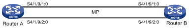
MP binding mode configuration examples
Network requirements
As showed in Figure 5, Router A and Router B are connected together through interfaces Serial 4/1/9/1:0 and Serial 4/1/9/2:0. It is desired to bind the links in MP-group binding mode.
Configuration procedure
1. Configure Router A:
# Configure the username and password of Router B on Router A.
<RouterA> system-view
[RouterA] local-user rtb
[RouterA-luser-rtb] password simple rtbbbbbbbbb
[RouterA-luser-rtb] service-type ppp
[RouterA-luser-rtb] quit
# Create an MP-group interface, and assign an IP address to it.
[RouterA] interface Mp-group 4/1/1
[RouterA-Mp-group4/1/1] ip address 111.1.1.1 24
# Configure Serial 4/1/9/1:0.
[RouterA-Mp-group4/1/1] interface Serial 4/1/9/1:0
[RouterA-Serial4/1/9/1:0] link-protocol ppp
[RouterA-Serial4/1/9/1:0] ppp authentication-mode pap domain system
[RouterA-Serial4/1/9/1:0] ppp pap local-user rta password simple rtaaaaaaaaa
[RouterA-Serial4/1/9/1:0] ppp mp Mp-group 4/1/1
[RouterA-Serial4/1/9/1:0] shutdown
[RouterA-Serial4/1/9/1:0] undo shutdown
[RouterA-Serial4/1/9/1:0] quit
# Configure Serial 4/1/9/2:0.
[RouterA] interface Serial 4/1/9/2:0
[RouterA-Serial4/1/9/2:0] link-protocol ppp
[RouterA-Serial4/1/9/2:0] ppp authentication-mode pap domain system
[RouterA-Serial4/1/9/2:0] ppp pap local-user rta password simple rtaaaaaaaaa
[RouterA-Serial4/1/9/2:0] ppp mp Mp-group 4/1/1
[RouterA-Serial4/1/9/2:0] shutdown
[RouterA-Serial4/1/9/2:0] undo shutdown
[RouterA-Serial4/1/9/2:0] quit
# Configure local authentication for the PPP users in the default ISP domain system.
[RouterA] domain system
[RouterA-isp-system] authentication ppp local
[RouterA-isp-system] quit
2. Configure Router B:
# Configure username and password for Router A on Router B.
<RouterB> system-view
[RouterB] local-user rta
[RouterB-luser-rta] password simple rtaaaaaaaaa
[RouterB-luser-rta] service-type ppp
[RouterB-luser-rta] quit
# Create an MP-group interface and assign an IP address to it.
[RouterB] interface Mp-group 4/1/1
[RouterB-Mp-group4/1/1] ip address 111.1.1.2 24
[RouterB-Mp-group4/1/1] quit
# Configure Serial 4/1/9/1:0.
[RouterB] interface Serial 4/1/9/1:0
[RouterB-Serial4/1/9/1:0] link-protocol ppp
[RouterB-Serial4/1/9/1:0] ppp authentication-mode pap domain system
[RouterB-Serial4/1/9/1:0] ppp pap local-user rtb password simple rtbbbbbbbbb
[RouterB-Serial4/1/9/1:0] ppp mp Mp-group 4/1/1
[RouterB-Serial4/1/9/1:0] shutdown
[RouterB-Serial4/1/9/1:0] undo shutdown
[RouterB-Serial4/1/9/1:0] quit
# Configure Serial 4/1/9/2:0.
[RouterB] interface Serial 4/1/9/2:0
[RouterB-Serial4/1/9/2:0] link-protocol ppp
[RouterB-Serial4/1/9/2:0] ppp authentication-mode pap domain system
[RouterB-Serial4/1/9/2:0] ppp pap local-user rtb password simple rtbbbbbbbbb
[RouterB-Serial4/1/9/2:0] ppp mp Mp-group 4/1/1
[RouterB-Serial4/1/9/2:0] shutdown
[RouterB-Serial4/1/9/2:0] undo shutdown
[RouterB-Serial4/1/9/2:0] quit
# Configure local authentication for the PPP users in the default ISP domain system.
[RouterB] domain system
[RouterB-isp-system] authentication ppp local
[RouterB-isp-system] quit
3. Verify the configuration:
[RouterA] display ppp mp
Mp-group is Mp-group4/1/1
max-bind: 16, fragment:enable, min-fragment: 512
Bundle Multilink, 2 members, Master link is Mp-group4/1/1
Peer's endPoint descriptor: Mp-group4/1/1
Bundle Up Time: 2007/06/29 10:45:11:562
0 lost fragments, 0 reordered, 0 unassigned
Sequence: 0/0 rcvd/sent
The member channels bundled are:
Serial4/1/9/1:0 Up-Time:2007/06/29 11:07:29:167
Serial4/1/9/2:0 Up-Time:2007/06/29 11:07:29:192
# Check the state of MP-group 4/1/1.
[RouterA] display interface Mp-group 4/1/1
Mp-group4/1/1 current state: UP
Line protocol current state: UP
Description: Mp-group4/1/1 Interface
The Maximum Transmit Unit is 1200, Hold timer is 10(sec)
Internet Address is 6.0.0.1/24 Primary
Link layer protocol is PPP
LCP opened, MP opened, IPCP opened, OSICP opened
Physical is MP, baudrate: 18432000 bps
Last 300 seconds input: 84 bytes/sec 1 packets/sec
Last 300 seconds output: 80 bytes/sec 1 packets/sec
846 packets input, 61121 bytes, 0 drops
825 packets output, 61030 bytes, 0 drops
# Ping IP address 111.1.1.2 on Router A.
[RouterA] ping 111.1.1.2
PING 111.1.1.2: 56 data bytes, press CTRL_C to break
Reply from 111.1.1.2: bytes=56 Sequence=1 ttl=255 time=29 ms
Reply from 111.1.1.2: bytes=56 Sequence=2 ttl=255 time=31 ms
Reply from 111.1.1.2: bytes=56 Sequence=3 ttl=255 time=29 ms
Reply from 111.1.1.2: bytes=56 Sequence=4 ttl=255 time=30 ms
Reply from 111.1.1.2: bytes=56 Sequence=5 ttl=255 time=30 ms
--- 111.1.1.2 ping statistics ---
5 packet(s) transmitted
5 packet(s) received
0.00% packet loss
round-trip min/avg/max = 29/29/31 ms
Troubleshooting PPP configuration
A link cannot revert to the up state
Symptom
PPP authentication failed and the link cannot revert to the up state.
Analysis
This problem may arise if the parameters for authentication are incorrect.
Solution
Enable the debugging of PPP, and you will see the information describing that LCP went up upon a successful LCP negotiation but went down after the PAP or CHAP negotiation. Check the PPP authentication settings at the local and peer ends to make sure that they are consistent.
A physical link remains down
Symptom
A physical link remains down.
Analysis
A physical link is in the down state:
· The interface is not brought up.
· The interface is administratively shut down.
· LCP negotiation fails.
Solution
Execute the display interface serial command to check the state of the interface for the failure cause.
The following table describes the possible states of an interface.
Table 1 Description on the states of an interface and the corresponding output
|
Output |
Description |
|
Serial2/1/9/1:0 current state: Administratively DOWN Line protocol current state: DOWN |
The interface has been shut down by the administrator. |
|
Serial2/1/9/2:0 current state: DOWN Line protocol current state: DOWN |
The interface has not been brought up yet or the physical layer is down. |
|
Serial2/1/9/2:0 current state: UP Line protocol current state: UP |
LCP negotiation has succeeded. |
|
Serial2/1/9/2:0 current state: UP Line protocol current state: DOWN |
The interface has been brought up but its LCP negotiation failed. |
A link remains down after IPv6CP negotiation fails
Symptom
Configure an IPv6 address on a PPP-encapsulated interface when IPv6 is disabled. The PPP link fails IPv6CP negotiation and cannot go up. After enabling IPv6, the interface still cannot go up.
Analysis
IPv6CP negotiation cannot succeed when IPv6 is disabled. As IPv6CP does not support re-negotiation, IPv6CP negotiation cannot succeed even if you enable IPv6 subsequently.
Solution
To resolve the problem, do the following:
· Enable IPv6 before configuring an IPv6 address on a PPP link.
· If IPv6CP negotiation fails, re-enable the interface with the shutdown command and the undo shutdown command to re-enable IPv6CP negotiation.