- Table of Contents
- Related Documents
-
| Title | Size | Download |
|---|---|---|
| 01-ATM Configuration | 297.98 KB |
Overview of IPoA, IPoEoA, and EoA
Configuring an ATM subinterface
Configuring an ATM subinterface
Associating the protocol state of an ATM P2P subinterface with the state of its PVC
Configuring applications carried by ATM
Displaying and maintaining ATM
An ATM interface is always down
PVC state is down while ATM interface state is up
Excessive packet drops/CRC errors or interface flapping occurs
Pinging opposite end attempts always fail
Overview
Introduction to ATM
Asynchronous Transfer Mode (ATM) is a technology based on packet transmission mode while incorporating the high speed of circuit transmission mode. It can satisfy the needs of various communication services. ATM was specified as a broadband ISDN transmission and switching mode by the ITU-T in June 1992. Due to its flexibility and support for multimedia services, it is regarded as the core technology for broadband communications.
As defined by the ITU-T, ATM encapsulates data in cells. Each ATM cell is 53 bytes long, among which 5 bytes are the cell header and the remaining 48 bytes are the payload. The major function of the cell header is to identify virtual connection, with limited functions regarding flow control, congestion control, and error control.
ATM connection
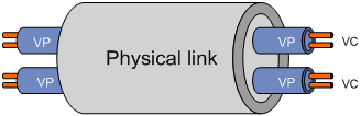
ATM is connection-oriented and ATM connections are logical connections, or virtual circuits. In an ATM network, you can create logical connections called virtual paths (VPs) and virtual circuits (VCs) on physical links. As shown in Figure 1, you can create multiple VPs on a physical link, and each VP can be demultiplexed into multiple VCs. Cells from different users are transmitted over different VPs and VCs, which are identified by virtual path identifier (VPI) and virtual channel identifier (VCI).
Figure 1 Physical link, VP, and VC
|
|
NOTE: ATM uses VPI/VCI pairs to identify a logical connection. When a connection is released, all the involved VPI/VCI pairs are reclaimed for new connections. |
ATM interfaces of the router support permanent virtual circuits (PVCs) only.
ATM architecture
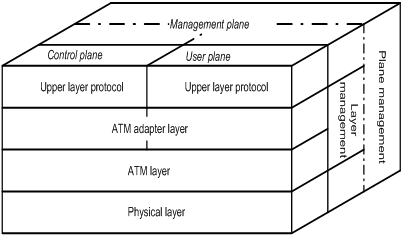
ATM has a three-dimensional architecture. It consists of three planes: user plane, control plane, and management plane. Both the user plane and the control plane are broken down into four layers, namely, physical layer, ATM layer, ATM Adaptation Layer (AAL), and upper layer, each of which are further divided into sub-layers.
· The control plane takes charge of establishing and tearing down connections using signaling protocols.
· The management plane consists of layer management and plane management. The former takes charge of managing the layers in each plane and has a layered structure corresponding to other planes. The latter is responsible for system management and communications between different planes.
The following figure illustrates the relationships between the layers and the planes in ATM.
Figure 2 ATM architecture
The functions of the four ATM layers are as follows:
· The physical layer mainly provides transmission channels for ATM cells. At this layer, cells passed from the ATM layer become continuous bit stream after transmission overheads are added to them. In addition, continuous bit streams received from the physical media are restored to cells on this, which are then passed to the ATM layer.
· The ATM layer, residing over the physical layer, implements cell-based communication with peer layers by invoking the services provided by the physical layer. It is independent of physical media and the implementation of the physical layer, as well as the types of the services being carried. Data passed to this layer takes the form of 48-byte payloads, known as segmentation and reassembly protocol data units (SAR-PDUs); and data passed from this layer to the physical layer is 53-byte cells, with the 48-byte payload being encapsulated in a 5-byte header. Other functions of the ATM layer include VPI/VCI transmission, cell multiplexing/demultiplexing, and generic flow control.
· ATM Adaptation Layer (AAL) provides interfaces between high-level protocols and the ATM Layer. It is responsible for forwarding the information between ATM layer and upper layer protocols. At present, four types of AAL are available: AAL1, AAL2, AAL3/4, and AAL5, each of which supports specific services provided in an ATM network. Most ATM equipment vendors adopt AAL5 for data communication services.
· ATM upper layer protocols take charge of WAN interconnection, voice interconnection, Layer 3 interconnection, encapsulation, LAN emulation, multi-protocol over ATM, and traditional IP.
Overview of IPoA, IPoEoA, and EoA
ATM interfaces support IPoA, IPoEoA, and EoA.
IPoA
IP over ATM (IPoA) enables ATM to carry IP packets. In an IPoA implementation, ATM serves as the data link layer protocol for the IP hosts on the same network. To enable these hosts to communicate across an ATM network, IP packets must be encapsulated in ATM cells.
By making full use of the advantages of ATM, IPoA delivers excellent network performance and ubiquitous mature QoS assurance.
IPoEoA
IPoE over ATM (IPoEoA) adopts a three-layer architecture, with IP at the uppermost layer, IP over Ethernet (IPoE) in the middle, and IPoEoA at the bottom.
IPoEoA is suitable where Ethernet packets are to be forwarded through ATM interfaces. A typical application of IPoEoA is using ATM PVCs to connect your router to a remote access server over a long distance for high-speed access to the Internet. In this application, you must configure IPoEoA on the connecting ATM interfaces.
As for IPoEoA, you can associate multiple PVCs with one virtual Ethernet (VE) interface. PVCs associated with the same VE interface can communicate at Layer 2.
EoA
Ethernet over ATM (EoA) adopts a two-layer architecture, with Ethernet at the upper layer and EoA at the lower layer. It requires that Ethernet packets be forwarded through ATM interfaces.
With EoA, a router can implement Layer 2 unicast, broadcast, and multicast.
You can associate only one PVC with one virtual Ethernet bridge (VE-bridge) interface (also referred to as a Layer 2 VE interface).
ATM service types
ATM supports four service types: constant bit rate (CBR), unspecified bit rate (UBR), real-time variable bit rate (rt_VBR) and non-real-time variable bit rate (nrt_VBR). They are used for the QoS purpose.
CBR
CBR provides ensured and constant bandwidth. The bandwidth assigned to the CBR service is decided by the peak cell rate (PCR). For a station using the CBR service, ATM cells are sent at PCR continuously with assured QoS.
Usually, CBR is suitable for jitter-sensitive real-time applications such as audio and video.
rt_VBR
The rt_VBR service is provided for applications that have strict restrictions on delay and jitter, such as audio and video.
An rt_VBR connection is described by the PCR, sustainable cell rate (SCR) and maximum burst size (MBS). A station using the rt_VBR service is allowed to send burst traffic at PCR with the maximum traffic size being MBS without packet loss while the average cell rate being SCR.
nrt_VBR
The nrt_VBR service supports non-real-time applications with burst traffic. An nrt_VBR connection is described by PCR, SCR and MBS. The nrt_VBR service is suitable for applications that are sensitive to cell loss but not to delay.
UBR
Introduction to InARP
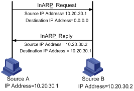
On an ATM PVC connection, you can use the Inverse Address Resolution Protocol (InARP) to obtain the IP address of the remote end connected to the PVC. Thus, you do not need to manually configure the IP address of the remote end. The following figure shows how InARP works:
Figure 3 Inverse address resolution procedure of InARP
ATM OAM
OAM stands for Operation And Maintenance in the ITU-T I.610 recommendation (02/99) and Operation Administration and Maintenance in LUCENT APC User Manual (03/99).
Whichever expansion is adopted, OAM provides a way of detecting faults, isolating faults, and monitoring network performance without interrupting ongoing services. By inserting OAM cells, which are constructed in the standard ATM cell format, in cell streams, you can obtain specific information about the network.
OAM F5 loopback
The OAM F5 loopback function of ATM works as follows on a PVC:
Each side of the PVC sends OAM cells to its peer periodically. On receiving an OAM cell from the sender, the receiver returns the OAM cell to the sender. If the sender receives the cell within the specified period, it considers the PVC as normal. If the sender fails to receive a certain number of consecutive OAM cells sent by itself, the PVC is considered as faulty.
Two approaches are available for implementing the OAM F5 Loopback function: manual (OAMPing) and auto (OAM Frequency). In the OAMPing approach, you need to send OAM cells manually; this approach is usually used for diagnosis. In the OAM Frequency approach, you need to configure an ATM interface to send OAM cells regularly at a certain interval. The latter approach automatically checks link status.
OAM continuity check
When enabled, the OAM Continuity Check (CC) function periodically sends OAM cells to check whether a connection is idle or has failed.
The OAM CC function works as follows on a PVC:
One side of the PVC sends OAM cells to its peer, which checks the connection status based on these OAM cells.
ATM configuration task list
Complete the following tasks to configure ATM:
|
Task |
Remarks |
|
|
Required |
||
|
Optional |
||
|
Associating the protocol state of an ATM P2P subinterface with the state of its PVC |
||
|
Optional |
||
|
Required Use one of the approaches. |
||
Configuring an ATM interface
Depending on the actual networking environment and system requirements, you may be required to modify certain parameters of an ATM interface.
Note that except the mtu command, which can be configured on a subinterface, the ATM settings in this section must be modified in ATM main interface view, although they apply to the ATM main interface and subinterfaces at the same time.
To configure an ATM interface:
|
Step |
Command |
Remarks |
|
1. Enter system view. |
system-view |
N/A |
|
2. Enter ATM main interface view. |
interface atm interface-number |
N/A |
|
3. Set the clock mode. |
clock { master | slave } |
Optional. Slave by default. |
|
4. Set the framing format. |
frame-format { sdh | sonet } |
Optional. SDH STM-1/STM-4 by default. |
|
5. Enable payload scrambling. |
scramble |
Optional. Enabled by default. |
|
6. Enable loopback. |
loopback { cell | local | remote } |
Optional. Disabled by default. |
|
7. Configure the MTU. |
mtu mtu-number |
Optional. 1500 bytes by default. |
|
8. Set the signal degrade (SD) threshold and the signal fail (SF) threshold. |
threshold { sd | sf } value |
Optional. By default, the SD threshold is 10e-6, and the SF threshold is 10e-3. |
Configuring an ATM subinterface
Configuring an ATM subinterface
To configure an ATM subinterface:
|
Step |
Command |
Remarks |
|
1. Enter system view. |
system-view |
N/A |
|
2. Create an ATM subinterface and enter its view. |
interface atm interface-number.subnumber [ p2mp | p2p ] |
By default, the connection type of an ATM subinterface is point-to-multipoint (P2MP). |
|
3. Set the MTU for the ATM subinterface. |
mtu mtu-number |
Optional. 1500 bytes by default. |
|
4. Shut down the ATM subinterface. |
shutdown |
Optional. By default, ATM subinterfaces are up. |
|
|
CAUTION: The keywords p2mp and p2p are available with the interface atm interface-number.subnumber only when you are creating an ATM subinterface. If you are entering an existing ATM subinterface, the two keywords are not available. |
Associating the protocol state of an ATM P2P subinterface with the state of its PVC
By default, the protocol of an ATM P2P subinterface goes up or comes down depending on the state of the physical interface. However, you can configure the protocol state of an ATM P2P subinterface adaptive to the protocol state of the PVC on it in addition to the state of the physical interface. Thus, the protocol state of the subinterface is up only when both the physical interface and the PVC configured on the subinterface are up. Otherwise, the protocol state of the subinterface is down.
To associate the protocol state of an ATM P2P subinterface with the state of the PVC on it:
|
Step |
Command |
Remarks |
|
1. Enter system view. |
system-view |
N/A |
|
2. Create an ATM subinterface and enter its view. |
interface atm interface-number.subnumber p2p |
By default, the connection type of a subinterface is point-to-multipoint (P2MP). |
|
3. Associate the protocol state of the ATM P2P subinterface with the state of the PVC on it. |
atm-link check |
By default, the protocol state of an ATM P2P subinterface is consistent with the state of its physical interface. |
Configuring PVC parameters
|
Step |
Command |
Remarks |
|
1. Enter system view. |
system-view |
N/A |
|
2. Enter ATM main interface view or ATM subinterface view. |
interface atm { interface-number | interface-number.subnumber } |
N/A |
|
3. Configure the maximum number of PVCs allowed on the ATM interface (only available in ATM main interface view). |
pvc max-number max-number |
Optional. 1024 by default. This command restricts the total number of PVCs that can be created on an ATM main interface and its subinterfaces and is available only in ATM main interface view. |
|
4. Create a PVC and enter PVC view. |
pvc { pvc-name [ vpi/vci ] | vpi/vci } |
By default, no PVC is created. |
|
5. Start transmission and retransmission detection using OAM F5 Loopback cells. |
oam frequency frequency [ up up-count down down-count retry-frequency retry-frequency ] |
Optional. By default, OAM F5 Loopback cell transmission is disabled. However, if an OAM F5 Loopback cell is received, it should be responded. By default, up-count is 3, down-count is 5 and retry-frequency is 1 second. |
|
6. Enable the OAM continuity check (CC) function. |
oam cc end-to-end { both | sink | source } |
Optional. By default, OAM CC is disabled. · When you configure OAM CC on a PVC, you must configure one end of the PVC as the source and the other end as the sink. · On a PVC with the OAM CC function enabled, if the detecting end fails to receive CC cells within 3 seconds, the state of the PVC changes to down and will change to up only after CC cells or packets are received again. · When disabling OAM CC on a PVC, you must make sure that the role of the PVC in continuity check is the same as the one that has been enabled. For example, if you have enabled the PVC as both the CC cell source and the sink, you should perform the undo oam cc end-to-end both command rather than the undo oam cc end-to-end sink command to disable the function. · This command cannot be configured on the PVCs in a PVC group. |
|
7. Set the service type and rate-related parameters for the PVC. |
· Set the service type to constant bit rate (CBR): · Set the service type to unspecified bit rate (UBR), and set the
rate-related parameters: · Set the service type to nrt_VBR, and set the rate-related
parameters: · Set the service type to rt_VBR, and set the rate-related
parameters: |
Optional. By default, the service type of a PVC is UBR. You can use any of these four commands to configure a service type and its rate parameters for a PVC. Note the following: · A newly configured service type overwrites the old one. · Setting of the arguments cdvt-value, output-scr, and output-mbs does not take effect on the router. |
Configuring applications carried by ATM
IPoA, IPoEoA, and EoA are mutually exclusive on an ATM PVC.
Configuring IPoA
To configure IPoA on a PVC for it to carry IP packets:
|
Step |
Command |
Remarks |
|
1. Enter system view. |
system-view |
N/A |
|
2. Enter ATM interface view. |
interface atm { interface-number | interface-number.subnumber } |
N/A |
|
3. Create a PVC, and enter PVC view. |
pvc { pvc-name [ vpi/vci ] | vpi/vci } |
N/A |
|
4. Configure an IPoA mapping for the PVC. |
map ip { ip-address | default | inarp [ minutes ] } [ broadcast ] |
By default, no IPoA mapping is configured. If a mapping is configured, pseudo-broadcast is not supported by default. |
|
|
NOTE: · If you execute the map ip command with the broadcast keyword, which specifies pseudo broadcast, any broadcast packets received by the port on which the PVC is created will be duplicated to the PVC. Therefore, to propagate broadcast/multicast packets or enable broadcast/multicast on an ATM PVC, you must specify the broadcast keyword. · On PVCs created on P2P ATM subinterfaces, you must configure the map ip default broadcast command. |
Configuring IPoEoA
IPoEoA enables a PVC to carry Layer 3 Ethernet packets.
To configure IPoEoA on a PVC:
|
Step |
Command |
Remarks |
|
1. Enter system view. |
system-view |
N/A |
|
2. Create a Layer 3 virtual Ethernet (VE) interface. |
interface virtual-ethernet interface-number |
Assign an IP address to the VE interface rather than the ATM interface. The IP address assigned to the ATM interface is invalid for IPoEoA. |
|
3. Return to system view. |
quit |
N/A |
|
4. Enter ATM interface view. |
interface atm { interface-number | interface-number.subnumber } |
N/A |
|
5. Enable packet padding on the interface. |
eoapad enable |
Optional. Disabled by default. |
|
6. Create a PVC and enter its view. |
pvc { pvc-name [ vpi/vci ] | vpi/vci } |
N/A |
|
7. Configure an IPoEoA mapping on the PVC. |
map bridge virtual-ethernet interface-number |
No IPoEoA mapping is configured by default. |
|
|
NOTE: · For more information about Layer 3 VE interfaces, see Interface Configuration Guide. · The eoapad enable command is also enabled on the ATM subinterfaces when it is enabled on the ATM main interface. |
Configure EoA
EoA enables a PVC to carry Layer 2 Ethernet frames.
To configure EoA:
|
Step |
Command |
Remarks |
|
1. Enter system view. |
system-view |
N/A |
|
2. Create a VE-bridge interface. |
interface ve-bridge interface-number |
N/A |
|
3. Return to system view. |
quit |
N/A |
|
4. Enter ATM interface view. |
interface atm { interface-number | interface-number.subnumber } |
N/A |
|
5. Enable packet padding on the interface. |
eoapad enable |
Optional. Disabled by default. |
|
6. Create a PVC and enter the PVC view. |
pvc { pvc-name [ vpi/vci ] | vpi/vci } |
N/A |
|
7. Configure an EoA mapping for the PVC. |
map bridge ve-bridge interface-number |
N/A |
|
|
NOTE: The eoapad enable command is also enabled on the ATM subinterfaces when it is enabled on the ATM main interface. |
Displaying and maintaining ATM
|
Task |
Command |
Remarks |
|
Display ATM interface information. |
display atm interface atm [ interface-number | interface-number.subnumber ] [ | { begin | exclude | include } regular-expression ] |
Available in any view |
|
Display the configuration and state of ATM interfaces. |
display interface atm [ interface-number | interface-number.subnumber ] [ | { begin | exclude | include } regular-expression ] |
Available in any view |
|
Display information about PVCs. |
display atm pvc-info [ interface atm { interface-number | interface-number.subnumber } [ pvc { pvc-name [ vpi/vci ] | vpi/vci } ] ] [ | { begin | exclude | include } regular-expression ] |
Available in any view |
|
Display PVC mappings. |
display atm map-info [ interface atm { interface-number | interface-number.subnumber } [ pvc { pvc-name [ vpi/vci ] | vpi/vci } ] ] [ | { begin | exclude | include } regular-expression ] |
Available in any view |
|
Send OAM cells on a PVC on an ATM interface to test connectivity of the link. |
oamping interface atm { interface-number | interface-number.subnumber } pvc { pvc-name | vpi /vci } [ number timeout ] |
Available in ATM interface view The link is considered as having failed if no response has been returned before the specified timeout time expires. |
|
Shut down an ATM interface view. |
shutdown |
Available in ATM interface view |
|
Clear the statistics about all PVCs on an ATM interface. |
reset atm interface [ atm { interface-number | interface-number.subnumber } ] |
Available in user view |
ATM configuration examples
IPoA configuration example
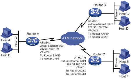
Network requirements
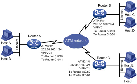
As shown in Figure 4, Router A, B and C are connected to an ATM network. The IP addresses of their ATM interfaces are 202.38.160.1/24, 202.38.160.2/24, and 202.38.160.3/24 respectively.
In the ATM network, the VPI/VCI pairs for the PVCs to Router B and Router C are 0/40 and 0/41 on Router A; the VPI/VCI pairs for the PVCs to Router A and Router C are 0/50 and 0/51 on Router B; and the VPI/VCI pairs for the PVCs to Router A and Router B on are 0/60 and 0/61 on Router C.
Configure IPoA encapsulation on all the PVCs on the ATM interfaces of the three routers.
Configuration procedure
1. Configure Router A:
# Enter the ATM main interface, and configure an IP address for it.
<RouterA> system-view
[RouterA] interface Atm 3/1/1
[RouterA-Atm3/1/1] ip address 202.38.160.1 255.255.255.0
# Create the PVCs to Router B and Router C and configure them to carry IP.
[RouterA-Atm3/1/1] pvc to_b 0/40
[RouterA-atm-pvc-Atm3/1/1-0/40-to_b] map ip 202.38.160.2 broadcast
[RouterA-atm-pvc-Atm3/1/1-0/40-to_b] quit
[RouterA-Atm3/1/1] pvc to_c 0/41
[RouterA-atm-pvc-Atm3/1/1-0/41-to_c] map ip 202.38.160.3 broadcast
2. Configure Router B:
# Enter the ATM main interface, and configure an IP address for it.
<RouterB> system-view
[RouterB] interface Atm 3/1/1
[RouterB-Atm3/1/1] ip address 202.38.160.2 255.255.255.0
# Create the PVCs to Router A and Router C and configure them to carry IP.
[RouterB-Atm3/1/1] pvc to_a 0/50
[RouterB-atm-pvc-Atm3/1/1-0/50-to_a] map ip 202.38.160.1 broadcast
[RouterB-atm-pvc-Atm3/1/1-0/50-to_a] quit
[RouterB-Atm3/1/1] pvc to_c 0/51
[RouterB-atm-pvc-Atm3/1/1-0/51-to_c] map ip 202.38.160.3 broadcast
3. Configure Router C:
# Enter the ATM main interface, and configure an IP address for it.
<RouterC> system-view
[RouterC] interface Atm 3/1/1
[RouterC-Atm3/1/1] ip address 202.38.160.3 255.255.255.0
# Create the PVCs to Router A and Router B and configure them to carry IP.
[RouterC-Atm3/1/1] pvc to_a 0/60
[RouterC-atm-pvc-Atm3/1/1-0/60-to_a] map ip 202.38.160.1 broadcast
[RouterC-atm-pvc-Atm3/1/1-0/60-to_a] quit
[RouterC-Atm3/1/1] pvc to_b 0/61
[RouterC-atm-pvc-Atm3/1/1-0/61-to_b] map ip 202.38.160.2 broadcast
IPoEoA configuration example
Network requirements
As shown in Figure 5, Router A, B, and C are connected to an ATM network. The IP addresses of their Layer 3 VE interfaces are 202.38.160.1/24, 202.38.160.2/24, and 202.38.160.3/24 respectively.
In the ATM network, the VPI/VCI pairs for the PVCs to Router B and Router C are 0/40 and 0/41 on Router A; the VPI/VCI pairs for the PVCs to Router A and Router C are 0/50 and 0/51 on Router B; and the VPI/VCI pairs for the PVCs to Router A and Router B on are 0/60 and 0/61 on Router C.
Configure IPoEoA encapsulation on all the PVCs on the ATM interfaces of the three routers.
Configuration procedure
1. Configure Router A:
# Create a Layer 3 VE interface and configure an IP address for it.
<RouterA> system-view
[RouterA] interface Virtual-Ethernet 3/0/1
[RouterA-Virtual-Ethernet3/0/1] ip address 202.38.160.1 255.255.255.0
[RouterA-Virtual-Ethernet3/0/1] quit
# Create a PVC and enable IPoEoA on it.
[RouterA] interface Atm 3/1/1
[RouterA-Atm3/1/1] pvc to_b 0/40
[RouterA-atm-pvc-Atm3/1/1-0/40-to_b] map bridge Virtual-Ethernet 3/0/1
[RouterA-atm-pvc-Atm3/1/1-0/40-to_b] quit
[RouterA-Atm3/1/1] pvc to_c 0/41
[RouterA-atm-pvc-Atm3/1/1-0/41-to_c] map bridge Virtual-Ethernet 3/0/1
2. Configure Router B:
# Create a Layer 3 VE interface and configure an IP address for it.
<RouterB> system-view
[RouterB] interface Virtual-Ethernet 3/0/1
[RouterB-Virtual-Ethernet3/0/1] ip address 202.38.160.2 255.255.255.0
[RouterB-Virtual-Ethernet3/0/1] quit
# Create the PVCs to Router A and Router C and configure them to carry IPoE.
[RouterB] interface Atm 3/1/1
[RouterB-Atm3/1/1] pvc to_a 0/50
[RouterB-atm-pvc-Atm3/1/1-0/50-to_a] map bridge Virtual-Ethernet 3/0/1
[RouterB-atm-pvc-Atm3/1/1-0/50-to_a] quit
[RouterB-Atm3/1/1] pvc to_c 0/51
[RouterB-atm-pvc-Atm3/1/1-0/51-to_c] map bridge Virtual-Ethernet 3/0/1
3. Configure Router C:
# Create a Layer 3 VE interface and configure an IP address for it.
<RouterC> system-view
[RouterC] interface Virtual-Ethernet 3/0/1
[RouterC-Virtual-Ethernet3/0/1] ip address 202.38.160.3 255.255.255.0
[RouterC-Virtual-Ethernet3/0/1] quit
# Create the PVCs to Router A and Router B and configure them to carry IPoE.
[RouterC] interface Atm 3/1/1
[RouterC-Atm3/1/1] pvc to_a 0/60
[RouterC-atm-pvc-Atm3/1/1-0/60-to_a] map bridge Virtual-Ethernet 3/0/1
[RouterC-atm-pvc-Atm3/1/1-0/60-to_a] quit
[RouterC-Atm3/1/1] pvc to_b 0/61
[RouterC-atm-pvc-Atm3/1/1-0/61-to_b] map bridge Virtual-Ethernet 3/0/1
EoA configuration example
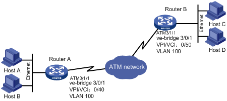
Network requirements
As shown in Figure 6, Router A and Router B are connected to an ATM network.
In the ATM network, the VPI/VCI pair for the PVC to Router B is 0/40 on Router A; the VPI/VCI pair for the PVC to Router A is 0/50 on Router B.
Configure VE-bridge interfaces (Layer 2 interfaces) on Router A and Router B to enable them to communicate at Layer 2 and configure EoA encapsulation on all the PVCs on the ATM interfaces of the routers.
Configuration procedure
1. Configure Router A:
# Create Layer 2 VE interfaces and assign them to the specified VLAN.
<RouterA> system-view
[RouterA] vlan 100
[RouterA-vlan100] quit
[RouterA] interface VE-Bridge 3/0/1
[RouterA-VE-Bridge3/0/1] port access vlan 100
[RouterA-VE-Bridge3/0/1] quit
# Create the PVCs to Router B and Router C and map them to the VE-bridge interfaces.
[RouterA] interface Atm 3/1/1
[RouterA-Atm3/1/1] pvc to_b 0/40
[RouterA-atm-pvc-Atm3/1/1-0/40-to_b] map bridge VE-Bridge 3/0/1
[RouterA-atm-pvc-Atm3/1/1-0/40-to_b] quit
2. Configure Router B:
# Create Layer 2 VE interfaces and assign them to the specified VLAN.
<RouterB> system-view
[RouterB] vlan 100
[RouterB-vlan100] quit
[RouterB] interface VE-Bridge 3/0/1
[RouterB-VE-Bridge3/0/1] port access vlan 100
[RouterB-VE-Bridge3/0/1] quit
# Create the PVCs to Router A and Router C and map them to the VE-bridge interfaces.
[RouterB] interface Atm 3/1/1
[RouterB-Atm3/1/1] pvc to_a 0/50
[RouterB-atm-pvc-Atm3/1/1-0/50-to_a] map bridge VE-Bridge 3/0/1
[RouterB-atm-pvc-Atm3/1/1-0/50-to_a] quit
Troubleshooting ATM
An ATM interface is always down
Symptom
The state of an ATM interface is always down.
Solution
Check the fiber connections of the ATM interface for inverse connections. The ATM interface can go up only when the transmit fiber and receive fiber are correctly connected.
If two routers are connected back-to-back, check the ATM interfaces for the same clock mode. By default, the clock mode on a router is slave, namely, adopting the line clock. If two routers are connected back-to-back, you must configure the clock mode at one side as master to provide clock reference, while the other side adopts the slave clock mode.
PVC state is down while ATM interface state is up
Symptom
The state of a PVC is down while its ATM interface is up.
Solution
Check if this fault results from enabling OAM F5 Loopback cell transmission and retransmission detection or OAM continuity check. When two ATM routers are connected, the VPI/VCI value of the PVCs on the two routers must be the same. Provided that OAM F5 cell transmission and retransmission detection or OAM continuity check is enabled, and the VPI/VCI value of the remote node (connected directly with the local node) is not the same as the local node, the local PVC state cannot change into UP.
Excessive packet drops/CRC errors or interface flapping occurs
Symptom
Two routers are connected back-to-back and can ping each other, but excessive packet drops and CRC errors or interface flapping up and down occurs occasionally.
Solution
Check the connecting ATM interfaces for fiber type inconsistency. If one side is a multi-mode fiber-optic interface while the other side is a single-mode fiber-optic interface, replace one interface to make sure that the same fiber-mode interfaces are used.
The symptom is occasional with the connection between ATM interfaces of different fiber-optic modes, which can work normally in most cases.
Pinging opposite end attempts always fail
Symptom
The physical layer and the line protocol of an ATM interface are both up, but the opposite end cannot be pinged.
Solution
To resolve the problem, do the following:
· If IPoA is used, make sure that the IP protocol address mappings are configured correctly. If the interfaces of two routers are connected back-to-back, the local PVC mapped to the remote IP must be configured with the same VPI/VCI value as the remote PVC mapped to the local IP address. In addition, the IP addresses of the two ends must be in the same network segment.
· If two routers are connected back-to-back, make sure that the connecting interfaces are configured with different clock modes, that is, master at one end and slave at the other end. If you router is connected to an ATM network, the clock mode on the ATM interface must be slave.
· Check the connecting ATM interfaces to make sure that they are of the same fiber-optic mode, that is, both are multimode fiber interfaces or both are single mode fiber interfaces. In addition, make sure that the mode of the connecting fibers is the same as that of the interfaces. (A multi-mode fiber-optic interface can communicate with a directly connected single-mode fiber-optic interface normally, but occasional excessive packet loss and CRC errors may occur sometimes.)
· If large ping packets cannot pass through while small ping packets can, check the MTU settings at the two ends to make sure that the same MTU is configured at the two ends.
· Check that the PVC is up.
· Check that the same AAL5 encapsulation format is used at the two ends.
· Check that the PVC mappings for the PVC are consistent at the two ends.
· Check that the same framing format is configured at the two ends.
· Check that the same overhead byte setting is adopted at the two ends.
· Check that the same scrambling mode is adopted at the two ends.