- Table of Contents
-
- 03-Layer 2 - LAN Switching Configuration Guide
- 00-Preface
- 01-VLAN Configuration
- 02-MAC Address Table Configuration
- 03-Spanning Tree Configuration
- 04-Ethernet Link Aggregation Configuration
- 05-Port Isolation Configuration
- 06-QinQ Configuration
- 07-BPDU Tunneling Configuration
- 08-GVRP Configuration
- 09-VLAN Termination Configuration
- 10-LLDP Configuration
- Related Documents
-
| Title | Size | Download |
|---|---|---|
| 09-VLAN Termination Configuration | 275.84 KB |
Contents
Introduction to VLAN termination
VLAN termination configuration task list
Configuring TPID for VLAN-tagged packets
Configuring TPID on a Layer 3 Ethernet/aggregate subinterface
Configuring TPID on a Layer 2 Ethernet or aggregate interface
Configuring unambiguous QinQ termination
Configuring ambiguous QinQ termination
VLAN termination configuration examples
Unambiguous QinQ termination configuration example
Ambiguous QinQ termination configuration example
Configuration example for QinQ termination supporting DHCP relay
|
|
NOTE: · In this documentation, SPC cards refer to the cards prefixed with SPC, for example, SPC-GT48L, and SPE cards refer to the cards prefixed with SPE, for example, SPE-1020-E-II. · Only the SPE cards support VLAN termination. |
Overview
Introduction to VLAN termination
VLAN termination refers to the following packet processing procedure:
· A port receives a VLAN-tagged packet, removes its VLAN tag(s) and then forwards it via Layer 3 or processes it in other ways. Whether the packet is tagged before being sent out depends on the port configuration.
· Before sending a packet, the port adds related VLAN information to it.
VLAN termination types
Based on the number of tags a VLAN-tagged packet carries, the VLAN-tagged packets falls into the following types:
· Dot1q packet (also known as an 802.1q packet), which carries a single VLAN tag
· QinQ packet, which carries double VLAN tags
Accordingly, VLAN termination falls into the following types:
· Dot1q termination—Terminates Dot1q packets and removes a Dot1q packet’s single VLAN tag.
· QinQ termination—Terminates QinQ packets and removes a QinQ packet’s inner and outer VLAN tags.
|
|
NOTE: · The router only supports QinQ termination. · A Layer 3 Ethernet interface cannot process VLAN-tagged packets, but you can create subinterfaces for it to process VLAN-tagged packets. · A Layer 3 Ethernet subinterface receives and sends only VLAN-tagged packets. |
Application scenarios
VLAN termination is mainly used for the following purposes:
Inter-VLAN communication
VLAN technology is widely used to isolate Layer 2 packets. It divides a LAN into multiple virtual LANs (VLANs) with each being a broadcast domain. Hosts within a VLAN can communicate with each other directly, whereas hosts in different VLANs are isolated at Layer 2. To allow different VLANs to communicate, Layer 3 routing must be used. You can configure the following methods to implement VLAN communication:
· Configuring VLAN interfaces on routers, as shown in Figure 1.
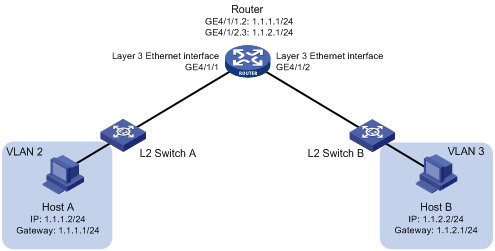
· Configuring Layer 3 Ethernet subinterfaces on routers, as shown in Figure 2.
As shown in Figure 1 and Figure 2, Host A belongs to VLAN 2, and Host B belongs to VLAN 3. After you specify Host A’s gateway IP address as 1.1.1.1/24 and Host B’s gateway IP address as 1.1.2.1/24, Host A and Host B can communicate at Layer 3 through VLAN interfaces or Layer 3 Ethernet subinterfaces.
Figure 1 VLAN termination for inter-VLAN communication (through VLAN interfaces)
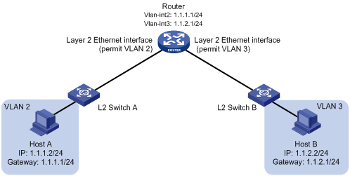
Figure 2 VLAN termination for inter-VLAN communication (through Layer 3 Ethernet subinterfaces)
LAN-WAN communication
Most packets sent out LANs carry VLAN tags, but some WAN protocols such as ATM, Frame Relay, and PPP cannot recognize VLAN tagged packets. Therefore, before sending VLAN-tagged packets to a WAN, the sending port must record and remove the VLAN information of the packets. VLAN interfaces or Layer 3 Ethernet subinterfaces can be used for LAN-WAN communication.
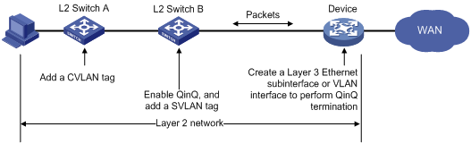
As shown in Figure 3, the VLANs of the customer network are called customer VLANs (CVLANs), and the VLANs of the service provider network are called service provider VLANs (SVLANs). When a packet carrying a CVLAN tag enters the service provider network, it is tagged with a SVLAN tag, and forwarded based on the SVLAN tag. When the packet is to be forwarded to an external WAN, the gateway (Device) must perform VLAN termination for the packet and remove the two layers of VLAN tags from the packet before sending the packet to the WAN.
Figure 3 VLAN termination enables LAN-WAN communication
VLAN termination configuration task list
Complete the following tasks to configure VLAN termination:
|
Task |
Remarks |
|
Optional |
|
|
Optional |
|
|
Required |
Configuring TPID for VLAN-tagged packets
IEEE 802.1Q inserts a four-byte VLAN tag field between the DA&SA field and the type field to carry VLAN-related information in an Ethernet frame header. Figure 4 shows the subfields in the VLAN tag field in Ethernet II encapsulation. Other Ethernet encapsulation formats include 802.2 LLC, 802.2 SNAP, and 802.3 raw. Figure 5 compares the structure of a Dot1q packet and that of a QinQ packet.
Figure 4 Subfields in the VLAN Tag field
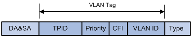
Figure 5 Compare the structure of a Dot1q packet and that of a QinQ packet
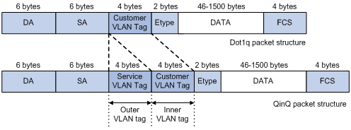
The VLAN tag field contains the following subfields: Tag Protocol Identifier (TPID), Priority, Canonical Format Indicator (CFI), and VLAN ID. Among these four subfields, TPID indicates whether an Ethernet packet carries a VLAN tag, or whether the packet is a VLAN-tagged packet. The TPID subfield contains 16 bits and usually takes the value of 0x8100. However, each vendor can define their own TPID value.
To enable the interfaces to recognize VLAN-tagged packets whose TPID is not 0x8100 and communicate with other vendors’ devices, the router provides the TPID configuration function. After TPID is configured,
· When receiving a packet, the device processes the packet according to Table 1.
Table 1 TPID-based processing for a received packet
|
TPID in outer VLAN tag |
TPID in inner VLAN tag |
Process the packet as… |
|
0x8100 or the user-defined value |
0x8100 |
A QinQ packet |
|
Not 0x8100 or the user-defined value |
N/A |
An untagged Ethernet packet |
· When sending out a packet, the router processes the packet according to Table 2.
Table 2 TPID-based processing for a packet to be sent
|
Whether a TPID value is defined by the user |
Set the TPID in the outer VLAN tag to… |
Set the TPID in the inner VLAN tag to… |
|
Yes |
User-defined value |
· 0x8100 if the packet has an inner VLAN tag · not set the TPID value if the packet has no inner VLAN tag |
|
No |
0x8100 |
|
|
NOTE: · If the current interface is up, upon the configuration of the TPID value, the interface will be shut down and then brought up to have the configuration take effect. · Even if you have used the dot1q ethernet-type command to define a TPID value other than 0x8100, the device always processes packets with TPID value 0x8100 as VLAN-tagged packets. However, when the device sends out a packet, it sets the packet’s TPID to the user-defined value. · The TPID values set on the local and peer devices must be consistent. Otherwise, packets may fail to be transmitted properly. |
Configuring TPID on a Layer 3 Ethernet/aggregate subinterface
To configure VLAN termination on a Layer 3 Ethernet subinterface or Layer 3 aggregate subinterface, follow these steps to configure the TPID value in the outer VLAN tag of packets received and sent by the subinterface:
|
Step |
Command |
Remarks |
|
1. Enter system view. |
system-view |
N/A |
|
2. Enter interface view. |
·
Enter Layer 3 Ethernet interface view: ·
Enter Layer 3 aggregate interface view: |
Use either command. Configurations made in Layer 3 Ethernet interface view take effect on all subinterfaces. Configurations made in Layer 3 aggregate interface view take effect on all the Layer 3 aggregate subinterfaces of the interface. |
|
3. Set the TPID value in the outer VLAN tag of packets received and sent by the interface. |
dot1q ethernet-type hex-value |
Optional. By default, the TPID value in the outer VLAN tag is 0x8100. If the interface receives and sends QinQ packets, the TPID value in the inner VLAN tag of packets is always 0x8100, and is not configurable. |
If not specified, the TPID value in the outer VLAN tag of packets takes the default value 0x8100.
Configuring TPID on a Layer 2 Ethernet or aggregate interface
To configure VLAN termination on a VLAN interface, set the TPID value in the outer VLAN tag of packets received and sent by Layer 2 physical interfaces in the corresponding VLAN. If not specified, the TPID value in the outer VLAN tag of packets takes the default value 0x8100.
To set the TPID value for VLAN-tagged packets on a Layer 2 Ethernet or aggregate interface:
|
Step |
Command |
Remarks |
|
1. Enter system view. |
system-view |
N/A |
|
2. Enter interface view. |
·
Enter Layer 2 Ethernet interface view: ·
Enter Layer 2 aggregate interface view: |
Use either command. Configurations made in Layer 2 aggregate interface view take effect on all the member interfaces in the aggregation group. |
|
3. Set the TPID value in the outer VLAN tag of packets received and sent by the interface. |
qinq ethernet-type [ service-tag ] hex-value |
Optional. By default, the TPID value in the outer VLAN tag is 0x8100. If the interface receives and sends QinQ packets, the TPID value in the inner VLAN tag of packets is always 0x8100, and is not configurable. |
|
|
NOTE: For more information about the qinq ethernet-type command, see Layer 2—LAN Switching Command Reference. |
Enabling a QinQ termination-enabled interface/subinterface to transmit broadcast and multicast packets
By default, an ambiguous QinQ termination-enabled subinterface or VLAN interface drops broadcast and multicast packets it receives, instead of transmitting them.
You can enable an ambiguous QinQ termination-enabled Layer 3 Ethernet/aggregate subinterface or VLAN interface to transmit broadcast and multicast packets.
To enable an ambiguous QinQ termination-enabled Layer 3 Ethernet/aggregate subinterface or VLAN interface to transmit broadcast and multicast packets:
|
Step |
Command |
Remarks |
|
1. Enter system view. |
system-view |
N/A |
|
2. Enter interface view. |
·
Enter Layer 3 Ethernet interface view: · Enter Layer 3 aggregate interface view: ·
Enter VLAN interface view: |
Use one of the commands. |
|
3. Enable the QinQ termination-enabled subinterface or VLAN interface to transmit broadcast and multicast packets. |
vlan-termination broadcast enable |
Optional. By default, a QinQ termination-enabled Layer 3 Ethernet/aggregate subinterface or VLAN interface does not transmit broadcast and multicast packets. |
Configuring QinQ termination
Based on the range of VLAN IDs in the VLAN-tagged packets that can be terminated by a subinterface, QinQ termination falls into the following two categories:
· Unambiguous QinQ termination—Terminates QinQ packets with the specified inner VLAN ID and outer VLAN ID. Any other QinQ packet is not allowed to pass through this subinterface. When a packet is sent out the subinterface, the packet is tagged with two VLAN tags as specified.
· Ambiguous QinQ termination—Terminates VLAN-tagged packets with the specified outer VLAN ID and the inner VLAN IDs in the specified range. These QinQ packets may have different inner VLAN IDs. VLAN-tagged packets whose inner VLAN IDs are not in the range are not allowed to pass through this subinterface. When a packet is sent out the subinterface, the packet is tagged with the specified outer VLAN ID and an inner VLAN ID: for an IPv4/MPLS packet, the inner VLAN ID is obtained by searching the ARP entries; for a PPPoE packet, the inner VLAN ID is obtained by searching the PPPoE session entries; for a DHCP relay packet, the inner VLAN ID is obtained by searching the DHCP session entries.
Configuring unambiguous QinQ termination
To configure unambiguous QinQ termination on a Layer 3 Ethernet subinterface, Layer 3 aggregate subinterface, or VLAN interface:
|
Step |
Command |
Remarks |
|
1. Enter system view |
system-view |
N/A |
|
2. Enter interface view. |
·
Enter Layer 3 Ethernet interface view: · Enter Layer 3 aggregate interface view: ·
Enter VLAN interface view: |
Use one of the commands. |
|
3. Enable QinQ termination on the subinterface or VLAN interface, and configure the subinterface or VLAN interface to terminate the QinQ packets with the specified inner VLAN ID. |
second-dot1q vlan-id |
The outer VLAN ID of the QinQ packets that can be terminated by the current subinterface or VLAN interface is the interface number, and is not configurable. |
|
|
NOTE: After you enable QinQ termination on a VLAN interface, Layer 2 Ethernet interfaces in the corresponding VLAN process only QinQ packets destined for the VLAN interface, and drop Dot1q and non-VLAN-tagged packets. |
Configuring ambiguous QinQ termination
To configure ambiguous QinQ termination on a Layer 3 Ethernet/aggregate subinterface or VLAN interface:
|
Step |
Command |
Remarks |
|
1. Enter system view. |
system-view |
N/A |
|
2. Enter interface view. |
·
Enter Layer 3 Ethernet interface view: · Enter Layer 3 aggregate interface view: ·
Enter VLAN interface view: |
Use one of the commands. |
|
3. Enable QinQ termination on the subinterface or VLAN interface, and configure the subinterface or VLAN interface to terminate the QinQ packets with the specified inner VLAN ID. |
second-dot1q { any | vlan-id-list } |
The outer VLAN ID of the QinQ packets that can be terminated by the current subinterface or VLAN interface is the interface number, and is not configurable. |
|
|
NOTE: After you enable QinQ termination on a VLAN interface, Layer 2 Ethernet interfaces in the corresponding VLAN process only QinQ packets destined for the VLAN interface, and drop Dot1q and non-VLAN-tagged packets. |
VLAN termination configuration examples
|
|
NOTE: Only the SPE cards support VLAN termination. |
Unambiguous QinQ termination configuration example
Network requirements
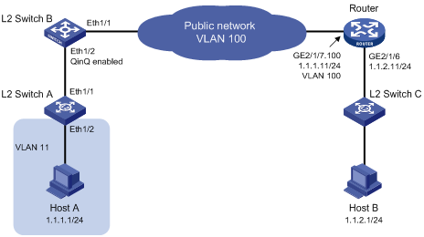
As shown in Figure 6, Host A connects to Switch A and belongs to VLAN 11. Host B connects to Switch C, which supports only single VLAN-tagged packets. With QinQ enabled, Switch B adds an outer VLAN tag with VLAN ID 100 to Dot1q packets carrying inner VLAN ID 11 before forwarding them. Host A needs to be able to communicate with Host B.
Configuration procedure
1. Configure Host A and Host B:
¡ Configure Host A’s IP address as 1.1.1.1/24, and gateway IP address as 1.1.1.11/24.
¡ Configure Host B’s IP address as 1.1.2.1/24, and gateway IP address as 1.1.2.11/24.
2. Configure Switch A:
<SwitchA> system-view
[SwitchA] vlan 11
[SwitchA-vlan11] port ethernet 1/2
[SwitchA-vlan11] quit
[SwitchA] interface ethernet 1/1
[SwitchA-Ethernet1/1] port link-type trunk
[SwitchA-Ethernet1/1] port trunk permit vlan 11
Please wait... Done.
3. Configure Switch B:
<SwitchB> system-view
[SwitchB] interface ethernet 1/2
[SwitchB-Ethernet1/2] port link-type trunk
[SwitchB-Ethernet1/2] port trunk permit vlan 11 100
Please wait... Done.
[SwitchB-Ethernet1/2] qinq enable
[SwitchB-Ethernet1/2] qinq vid 100
[SwitchB-Ethernet1/2-vid-100] raw-vlan-id inbound 11
[SwitchB-Ethernet1/2-vid-100] quit
[SwitchB-Ethernet1/2] quit
[SwitchB] interface ethernet 1/1
[SwitchB-Ethernet1/1] port link-type trunk
[SwitchB-Ethernet1/1] port trunk permit vlan 100
4. Configure the router:
# Create Ethernet subinterface GigabitEthernet 2/1/7.100 and enter subinterface view. Assign an IP address to the Ethernet subinterface, enable QinQ termination on it, and specify the inner VLAN ID of the QinQ packets that can be terminated by it.
<Router> system-view
[Router] interface GigabitEthernet2/1/7.100
[Router-GigabitEthernet2/1/7.100] ip address 1.1.1.11 255.255.255.0
[Router-GigabitEthernet2/1/7.100] second-dot1q 11
[Router-GigabitEthernet2/1/7.100] quit
[Router] interface GigabitEthernet 2/1/6
[Router-GigabitEthernet2/1/6] ip address 1.1.2.11 255.255.255.0
5. Configure Switch C:
Use Switch C’s factory configuration.
Ambiguous QinQ termination configuration example
Network requirements
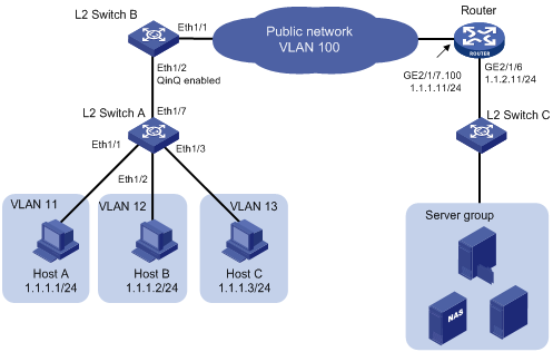
As shown in Figure 7, Host A, Host B and Host C are connected to Switch A and they belong to VLAN 11, VLAN 12 and VLAN 13 respectively. The server group is connected to Switch C. QinQ is enabled on Switch B. Host A, Host B, and Host C need to communicate with the server group.
Configuration procedure
1. Configure Host A, Host B, and Host C:
¡ Configure Host A’s IP address as 1.1.1.1/24, and gateway IP address as 1.1.1.11/24.
¡ Configure Host B’s IP address as 1.1.1.2/24, and gateway IP address as 1.1.1.11/24.
¡ Configure Host C’s IP address as 1.1.1.3/24, and gateway IP address as 1.1.1.11/24.
2. Configure Switch A:
<SwitchA> system-view
[SwitchA] vlan 11
[SwitchA-vlan11] port ethernet 1/1
[SwitchA-vlan11] quit
[SwitchA] vlan 12
[SwitchA-vlan12] port ethernet 1/2
[SwitchA-vlan12] quit
[SwitchA] vlan 13
[SwitchA-vlan13] port ethernet 1/3
[SwitchA-vlan13] quit
[SwitchA] interface ethernet 1/7
[SwitchA-Ethernet1/7] port link-type trunk
[SwitchA-Ethernet1/7] port trunk permit vlan 11 to 13
Please wait... Done.
3. Configure Switch B:
<SwitchB> system-view
[SwitchB] interface ethernet 1/2
[SwitchB-Ethernet1/2] port link-type trunk
[SwitchB-Ethernet1/2] port trunk permit vlan 11 to 13 100
Please wait... Done.
[SwitchB-Ethernet1/2] qinq enable
[SwitchB-Ethernet1/2] qinq vid 100
[SwitchB-Ethernet1/2-vid-100] raw-vlan-id inbound 11 to 13
[SwitchB-Ethernet1/2-vid-100] quit
[SwitchB-Ethernet1/2] quit
[SwitchB] interface ethernet 1/1
[SwitchB-Ethernet1/1] port link-type trunk
[SwitchB-Ethernet1/1] port trunk permit vlan 100
4. Configure the router:
# Create Ethernet subinterface GigabitEthernet 2/1/7.100 and enter subinterface view. Assign an IP address to the subinterface. Configure the subinterface to terminate QinQ packets whose inner VLAN ID is 11, 12, or 13, and outer VLAN ID is 100.
<Router> system-view
[Router] interface gigabitethernet 2/1/7.100
[Router-GigabitEthernet2/1/7.100] ip address 1.1.1.11 255.255.255.0
[Router-GigabitEthernet2/1/7.100] second-dot1q 11 to 13
[Router-GigabitEthernet2/1/7.100] quit
[Router] interface gigabitethernet 2/1/6
[Router-GigabitEthernet2/1/6] ip address 1.1.2.11 255.255.255.0
5. Configure Switch C:
Use Switch C’s factory configuration.
6. Configure the server group:
Assign IP addresses in the same network segment 1.1.2.0/24 to all devices in the server group, and configure the gateway IP address as 1.1.2.11/24.
Configuration example for QinQ termination supporting DHCP relay
Network requirements
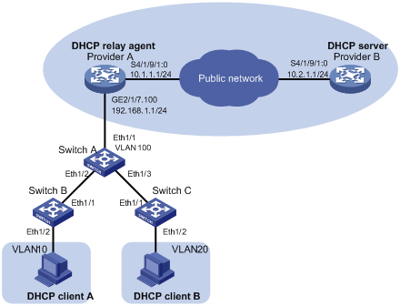
As shown in Figure 8:
· Provider A and Provider B are routers on the service provider network.
· DHCP client A and DHCP client B are routers on the customer networks.
· Provider A is the DHCP relay agent and Provider B is the DHCP server.
· Provider A and Provider B communicate with each other through Layer 3 interfaces.
The expected results after the configuration are:
· DHCP relay agent Provider A receives double-tagged packets sent from DHCP clients, terminates these QinQ packets by removing their inner and outer VLAN tags, and forwards the packets to DHCP server Provider B via the service provider network.
· DHCP client A and client B can apply for IP addresses and related network configuration parameters from Provider B via the service provider network.
Configuration procedure
1. Configure DHCP relay agent Provider A:
# Enable DHCP.
<ProviderA> system-view
[ProviderA] dhcp enable
# Create the DHCP server group.
[ProviderA] dhcp relay server-group 1 ip 10.2.1.1
# Create a Layer 3 Ethernet subinterface GigabitEthernet 2/1/7.100.
[ProviderA] interface GigabitEthernet2/1/7.100
# Configure subinterface GigabitEthernet 2/1/7.100 to terminate packets whose inner VLAN ID is 10 or 20.
[ProviderA-GigabitEthernet2/1/7.100] second-dot1q 10 20
# Enable DHCP relay on subinterface GigabitEthernet 2/1/7.100 and select a DHCP server group.
[ProviderA-GigabitEthernet2/1/7.100] dhcp select relay
[ProviderA-GigabitEthernet2/1/7.100] dhcp relay server-select 1
# Assign an IP address to subinterface GigabitEthernet 2/1/7.100.
[ProviderA-GigabitEthernet2/1/7.100] ip address 192.168.1.1 24
# Enable subinterface GigabitEthernet 2/1/7.100 to transmit broadcast and multicast packets.
[ProviderA-GigabitEthernet2/1/7.100] vlan-termination broadcast enable
[ProviderA-GigabitEthernet2/1/7.100] quit
# Assign an IP address to the interface connecting to the DHCP server.
[ProviderA] interface Serial 4/1/9/1:0
[ProviderA-Serial4/1/9/1:0] ip address 10.1.1.1 24
2. Configure DHCP server Provider B:
# Assign an IP address to the DHCP server.
<ProviderB> system-view
[ProviderB] interface Serial 4/1/9/1:0
[ProviderB-Serial4/1/9/1:0] ip address 10.2.1.1 24
[ProviderB-Serial4/1/9/1:0] quit
# Enable DHCP.
[ProviderB] dhcp enable
# Configure an IP address pool on the DHCP server.
[ProviderB] dhcp server ip-pool 1
[ProviderB-dhcp-pool-1] network 192.168.1.0 24
[ProviderB-dhcp-pool-1] gateway-list 192.168.1.1
[ProviderB-dhcp-pool-1] quit
# Configure a static route to GigabitEthernet 2/1/7.100.
[ProviderB] ip route-static 192.168.1.1 24 10.1.1.1
|
|
NOTE: The configuration steps below are for your reference only. The actual steps depend on the switches you use. |
3. Configure Switch A:
# Configure uplink port Ethernet 1/1.
<SwitchA> system-view
[SwitchA] interface ethernet 1/1
[SwitchA-Ethernet1/1] port link-type trunk
# Configure Ethernet 1/1 as a trunk port and assign it to VLAN 100.
[SwitchA-Ethernet1/1] port trunk permit vlan 100
[SwitchA-Ethernet1/1] quit
# Configure downlink port Ethernet 1/2.
[SwitchA] interface ethernet 1/2
[SwitchA-Ethernet1/2] qinq enable
[SwitchA-Ethernet1/2] quit
# Configure downlink port Ethernet 1/3.
[SwitchA] interface Ethernet 1/3
[SwitchA-Ethernet1/3] qinq enable
[SwitchA-Ethernet1/3] quit
# Assign downlink ports Ethernet 1/2 and Ethernet 1/3 to VLAN 100.
[SwitchA] vlan 100
[SwitchA-vlan100] port ethernet 1/2
[SwitchA-vlan100] port ethernet 1/3
4. Configure Switch B:
# Assign port Ethernet 1/2 to VLAN 20.
<SwitchB> system-view
[SwitchB] vlan 20
[SwitchB-vlan20] port ethernet 1/2
[SwitchB-vlan20] quit
# Configure port Ethernet 1/1 as a trunk port and assign it to VLAN 20.
[SwitchB] interface ethernet 1/1
[SwitchB-Ethernet1/1] port link-type trunk
[SwitchB-Ethernet1/1] port trunk permit vlan 20
5. Configure Switch C:
# Assign port Ethernet 1/2 to VLAN 10.
<SwitchC> system-view
[SwitchC] vlan 10
[SwitchC-vlan10] port ethernet 1/2
[SwitchC-vlan10] quit
# Configure Ethernet 1/1 as a trunk port and assign it to VLAN 10.
[SwitchC] interface ethernet 1/1
[SwitchC-Ethernet1/1] port link-type trunk
[SwitchC-Ethernet1/1] port trunk permit vlan 10