- Table of Contents
- Related Documents
-
| Title | Size | Download |
|---|---|---|
| 06-Software Upgrade Configuration | 358.76 KB |
Contents
Software upgrade configuration task list
Upgrading system software from BootWare menu
Using TFTP/FTP through Ethernet port
Using Xmodem through console port
Upgrading the BootWare program at the CLI
Upgrading the system boot file at the CLI
Specifying a boot file to be used at the next boot
Upgrading the boot file for the standby MPU
Upgrading software through hotfix
Hotfix configuration task list
Installing a patch in one step
Installing a patch step-by-step
Uninstalling all patches in one step·
Uninstalling a patch step-by-step
Displaying and maintaining software upgrade configuration
Software upgrade configuration examples
Remote upgrade configuration example
Router software overview
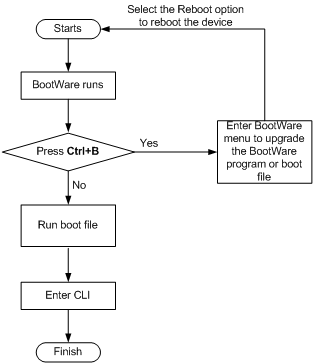
The router software comprises the BootWare program and the system boot file. After the router is powered on, it runs the BootWare program, checks the memory size, tests the memory functionality, initializes hardware, and displays the hardware information. Then the router runs the boot file. The boot file provides drivers and adaption for hardware, and implements service features, like forwarding, VLAN, and SNMP. The BootWare program and system boot file are required to start up and run the router. Figure 1 illustrates their relationship.
Figure 1 Relationship between the BootWare program and the system boot file
You can upgrade both the BootWare program and system boot file using the BootWare menu or at the command-line interface (CLI). The following sections cover how to upgrade software at the CLI. For more information about how to upgrade software using the BootWare menu, see the H3C SR8800 10G Core Routers Installation Guide.
Software upgrade configuration task list
|
Task |
Remarks |
|
Optional |
|
|
Optional |
|
|
Optional |
|
|
Optional |
|
|
Optional |
|
|
Optional |
Upgrading system software from BootWare menu
You can upgrade the system software from the BootWare menu by using one of the following methods:
· Using TFTP/FTP through Ethernet port
· Using Xmodem through console port
BootWare main menu
Upon startup, the router displays the following information:
SDRAM init successful.
System is starting...
****************************************************************************
* *
* H3C SR8800 BootWare, Version 203 *
* *
****************************************************************************
Copyright (c) 2004-2010 Hangzhou H3C Technologies Co., Ltd.
Compiled Date : Jan 29 2010
CPU Type : MPC7447A
CPU L1 Cache : 32KB
CPU L2 Cache : 512KB
CPU Clock Speed : 998MHz
Memory Type : SDRAM
Memory Size : 2048MB
Memory Speed : 133MHz
BootWare Size : 1MB
Flash Size : 128MB
cfa0 Size : 1024MB
NVRAM Size : 512KB
CPLD Version : 004
PCB Version : Ver.B
Board self testing...........................
Board steady testing... [ PASS ]
Board SlotNo... [ 0 ]
CPLD1 testing... [ PASS ]
CPLD2 testing... [ PASS ]
The switch's Mac address... [00:0F:E2:DE:86:00]
BootWare Validating...
Press Ctrl+B to enter extended boot menu...
|
|
NOTE: The output varies with router models. |
Press Ctrl+B when "Press Ctrl+B to enter extended BootWare menu..." appears.
Please input BootWare password:
Input the correct password to enter the BootWare main menu. (By default, no password is set, and press Enter to enter the menu. When a password is set, if you fail to input the correct password three times, the system hangs up, and you have to reboot the router.)
Note: The current operating device is cfa0
Enter < Storage Device Operation > to select device.
===========================<EXTEND-BOOTWARE MENU>===========================
|<1> Boot System |
|<2> Enter Serial SubMenu |
|<3> Enter Ethernet SubMenu |
|<4> File Control |
|<5> Modify BootWare Password |
|<6> BootWare Operation Menu |
|<7> Storage Device Operation |
|<0> Reboot |
============================================================================
Enter your choice(0-7):
BootWare submenus
Accessing the serial submenu
You can upgrade the system software and modify serial port parameters from the serial submenu.
Enter 2 in the BootWare main menu to access the serial submenu.
===========================<Enter Serial SubMenu>===========================
|Note:the operating device is cfa0 |
|<1> Download Application Program To SDRAM And Run |
|<2> Update Main Application File |
|<3> Update Backup Application File |
|<4> Update User Private File |
|<5> Modify Serial Interface Parameter |
|<0> Exit To Main Menu |
============================================================================
Enter your choice(0-5):
Accessing the Ethernet submenu
Enter 3 in the BootWare main menu to access the Ethernet submenu.
==========================<Enter Ethernet SubMenu>==========================
|Note:the operating device is cfa0 |
|<1> Download Application Program To SDRAM And Run |
|<2> Update Main Application File |
|<3> Update Backup Application File |
|<4> Update User Private File |
|<5> Modify Ethernet Parameter |
|<0> Exit To Main Menu |
|<Ensure The Parameter Be Modified Before Downloading!> |
============================================================================
Enter your choice(0-5):
Accessing the file control submenu
Enter 4 in the BootWare main menu to access the file control submenu, where you can display files, modify file names, and delete files.
===============================<File CONTROL>===============================
|Note:the operating device is cfa0 |
|<1> Display All File(s) |
|<2> Set Application File type |
|<3> Delete File |
|<0> Exit To Main Menu |
============================================================================
Enter your choice(0-3):
Table 1 File control submenu description
|
Item |
Description |
|
<1> Display All File(s) |
Display all files. |
|
<2> Set Application File type |
Set system software image type. Attributes main (M) and backup (B) determine the image type, such as type M, type B, or type M+B. An image can have any combination of M and B attributes, but there can only be one image for the same attribute. For example, if you specify an attribute for a new image, the original image with the specified attribute removes that attribute. If the original image has only one attribute, its type changes to N/A. |
|
<3> Delete File |
Delete files. |
|
<0> Exit To Main Menu |
Return to the BootWare main menu. |
Using TFTP/FTP through Ethernet port
1. Enter 3 in the BootWare main menu to access the Ethernet submenu, and then enter 6 to access the Ethernet parameter set menu.
==========================<ETHERNET PARAMETER SET>==========================
|Note: '.' = Clear field. |
| '-' = Go to previous field. |
| Ctrl+D = Quit. |
============================================================================
Protocol (FTP or TFTP) :ftp
Load File Name :
:main.bin
Target File Name :
:main.bin
Server IP Address :192.168.1.1
Local IP Address :192.168.1.2
Gateway IP Address :
FTP User Name :user
FTP User Password :password
Table 2 Parameter description
|
Field |
Description |
|
Load File Name |
Name for the downloaded file. |
|
Target File Name |
Name of the target file, identical with the name of the file on the server. |
2. Enter 2 to upgrade the main system software image.
Loading.....................................................................
............................................................................
............................................................................
............................................................................
............................................................................
............................................................................
............................................................................
............................................................................
............................................................................
..............................................................Done!
31911808 bytes downloaded!
Updating File cfa0:/main.bin. ................. ...........
....................................................Done!
==========================<Enter Ethernet SubMenu>==========================
|Note:the operating device is cfa0 |
|<1> Download Application Program To SDRAM And Run |
|<2> Update Main Application File |
|<3> Update Backup Application File |
|<4> Update User Private File |
|<5> Modify Ethernet Parameter |
|<0> Exit To Main Menu |
|<Ensure The Parameter Be Modified Before Downloading!> |
============================================================================
Enter your choice(0-5):
3. Enter 0 to return to the BootWare main menu, and then enter 1 to boot the system.
Using Xmodem through console port
1. Enter 2 in the BootWare main menu to access the serial submenu.
===========================<Enter Serial SubMenu>===========================
|Note:the operating device is cfa0 |
|<1> Download Application Program To SDRAM And Run |
|<2> Update Main Application File |
|<3> Update Backup Application File |
|<4> Update User Private File |
|<5> Modify Serial Interface Parameter |
|<0> Exit To Main Menu |
============================================================================
Enter your choice(0-5):
2. Enter 5 in the serial submenu to change the baud rate.
===============================<BAUDRATE SET>===============================
|Note:'*'indicates the current baudrate |
| Change The HyperTerminal's Baudrate Accordingly |
|---------------------------<Baudrate Available>---------------------------|
|<1> 9600(Default)* |
|<2> 19200 |
|<3> 38400 |
|<4> 57600 |
|<5> 115200 |
|<0> Exit |
============================================================================
Enter your choice(0-5):5
Select the baud rate that you want to use. For example, enter 5 to select 115200 bps. The following information appears:
Baudrate has been changed to 115200 bps.
Please change the terminal's baudrate to 115200 bps, press ENTER when ready.
|
|
NOTE: If you use the default baud rate 9600 bps, go to Step 7. |
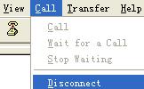
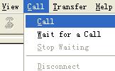
3. Disconnect the HyperTerminal from the router by selecting Call/Disconnect in the HyperTerminal window.
Figure 2 Disconnecting the terminal
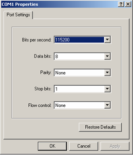
4. Select File > Properties in the HyperTerminal window, click Configure in the popup dialog box, and select the baud rate of 115200 bps in the console port properties dialog box.
Figure 3 Router Properties dialog box
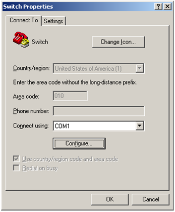
Figure 4 Changing the baud rate
5. Click Call/Call to re-connect to the router.
Figure 5 Connecting to the router
After you press Enter, the following information appears:
The current baudrate is 115200 bps
===============================<BAUDRATE SET>===============================
|Note:'*'indicates the current baudrate |
| Change The HyperTerminal's Baudrate Accordingly |
|---------------------------<Baudrate Available>---------------------------|
|<1> 9600(Default) |
|<2> 19200 |
|<3> 38400 |
|<4> 57600 |
|<5> 115200* |
|<0> Exit |
============================================================================
Enter your choice(0-5):
6. Type 0 to return to the serial submenu.
===========================<Enter Serial SubMenu>===========================
|Note:the operating device is cfa0 |
|<1> Download Application Program To SDRAM And Run |
|<2> Update Main Application File |
|<3> Update Backup Application File |
|<4> Update User Private File |
|<5> Modify Serial Interface Parameter |
|<0> Exit To Main Menu |
============================================================================
Enter your choice(0-5):
7. Enter 2 in the serial submenu to upgrade the main system software image.
Please Start To Transfer File, Press <Ctrl+C> To Exit.
Waiting ...CCCCC
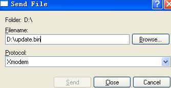
Select Transfer > Send File in the HyperTerminal window. In the Send File dialog box that appears, click Browse to select the target image update.bin, and select Xmodem as the protocol.
Figure 6 Send File dialog box
8. Click Send.
The following dialog box appears:
Figure 7 Sending the file by using XMODEM
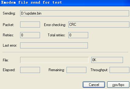
When the download is complete, the following information appears:
Download successfully!
31911808 bytes downloaded!
Input the File Name:main.bin
Updating File cfa0:/main.bin..............................................
.....................................................Done!
===========================<Enter Serial SubMenu>===========================
|Note:the operating device is cfa0 |
|<1> Download Application Program To SDRAM And Run |
|<2> Update Main Application File |
|<3> Update Backup Application File |
|<4> Update User Private File |
|<5> Modify Serial Interface Parameter |
|<0> Exit To Main Menu |
============================================================================
Enter your choice(0-5):
9. Enter 0 to return to the BootWare main menu, and then enter 1 to boot the system.
|
|
NOTE: · After the startup, change the baud rate of the HyperTerminal back to 9600 bps by following Step 3 through Step 5. · For higher speed, use the Ethernet port instead of the console port to download the system software image. |
Upgrading the BootWare program at the CLI
To upgrade the BootWare program:
1. Copy the new BootWare program to the root directory of the router's storage medium by using FTP or TFTP.
2. Use the following command to upgrade the BootWare program on a card or a list of cards:
|
Task |
Command |
Remarks |
|
Upgrade the BootWare program on a card or a list of cards. |
bootrom update file file-url slot slot-number-list |
Available in user view |
3. Reboot the router to make the specified BootWare program take effect.
|
|
NOTE: The system boot file (with the file extension.bin) comprises the BootWare program, which is automatically upgraded when the system boot file is upgraded. You can also manually upgrade the BootWare program by executing the bootrom update file command. |
Upgrading the system boot file at the CLI
Follow the steps to upgrade the boot file:
1. Save the boot file to the root directory of the storage media on the active MPU by using FTP, TFTP, or other approaches.
2. Copy the boot file to the root directory of the storage media on the standby MPU.
3. Specify the boot file to be used at the next boot of the active MPU and standby MPU respectively at the CLI.
4. Reboot the router to make the new boot file take effect.
Specifying a boot file to be used at the next boot
When multiple BootWare files are available on the storage media of the router, you can specify a file to be used at the next router boot by executing the following command. A main boot file is used to boot a router and a backup boot file is used to boot a router only when a main boot file is unavailable
To specify a file to be used at the next boot of the router:
|
Task |
Command |
Remarks |
|
Specify a file to be used at the next router boot on a card. |
boot-loader file file-url slot slot-number { main | backup } |
Available in user view. |
|
CAUTION: · The file for the next router boot must be saved in the root directory of the router. For a router with a partitioned storage media, the file must be saved on the first partition. You can copy or move a file to change the path of it to the root directory. · The names of the files for the next boot of the active MPU and the standby MPU may be different, but the versions of the files must be the same. Otherwise, the router may not boot normally. |
Upgrading the boot file for the standby MPU
If the versions of the active MPU and the standby MPU of a router are different, the standby MPU cannot operate normally. With this function, you can upgrade the standby MPU quickly.
If this function is enabled:
1. The router copies the current boot file of the active MPU to the standby MPU.
2. The router specifies this boot file as the boot file to be used at the next router boot for the standby MPU.
3. The standby MPU reboots automatically.
To upgrade the boot file for the standby MPU:
|
Task |
Command |
Remarks |
|
Upgrade the boot file for the standby MPU. |
boot-loader update slot slot-number |
Available in user view. |
Upgrading software through hotfix
A hotfix is a fast, cost-effective method to repair software defects of a router. Compared with another method, software version upgrade, a hotfix can upgrade the software without interrupting the services running on the router. In other words, it can repair the software defects of the current version without the need for a router reboot.
Basic concepts in hotfix
Patch and patch file
A patch, also called patch unit, is a package to fix software defects. Generally, patches are released as patch files. A patch file may contain one or more patches for different defects. When loaded from the storage media to the memory patch area, each patch is assigned a unique number, which starts from 1, for identification, management and operation. For example, if a patch file has three patch units, they are numbered as 1, 2, and 3 respectively.
Incremental patch
Patches in a patch file are all incremental patches. An incremental patch means that the patch is dependent on the previous patch units. For example, if a patch file has three patch units, patch 3 can be running only after patch 1 and 2 take effect. You cannot run patch 3 separately.
Common patch and temporary patch
Patches fall into two types, common patches and temporary patches.
· Common patches are those formally released through the version release flow.
Patch package
A patch package contains patches of the same version but for various types of cards. You can install a patch package on a distributed device or an IRF virtual device to upgrade the software of multiple cards at a time. When you execute a patch package, the system automatically finds out the proper patch for each card, and loads them to the cards, simplifying patch operation and patch version management.
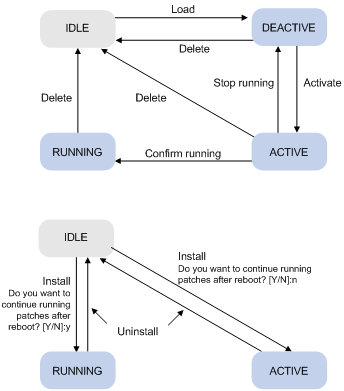
Patch state
Each patch has a state, which can be switched only by commands. The relationship between patch state changes and command actions is shown in Figure 8. The patch can be in IDLE, DEACTIVE, ACTIVE, or RUNNING state. Load, run temporarily, confirm running, stop running, delete, install, and uninstall represent operations, corresponding to commands of patch load, patch active, patch run, patch deactive, patch delete, patch install, and undo patch install.
For example, if you execute the patch active command for the patches in DEACTIVE state, the patches switch to ACTIVE state.
|
|
IMPORTANT: Patch state information is saved in Flash memory in the file patchstate. To make sure that the device can correctly find the patches, do not edit, delete, move the file, or change the file name. |
Figure 8 Relationship between patch state changes and command actions
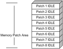
IDLE state
Patches in IDLE state are not loaded. You cannot activate or run the patches, as shown in Figure 9 (suppose the memory patch area can load up to eight patches). The patches that are in IDLE state are still in IDLE state after system reboot.
Figure 9 Patches are not loaded to the memory patch area
|
|
NOTE: Currently, the system patch area supports up to 200 patches. |
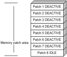
DEACTIVE state
Patches in DEACTIVE state have been loaded to the memory patch area but have not run in the system yet. Assume that there are seven patches in the patch file to be loaded. After the seven patches pass the version check and CRC check, they are loaded to the memory patch area and are in DEACTIVE state. The patch states in the system are as shown in Figure 10.
The patches that are in DEACTIVE state are still in DEACTIVE state after system reboot.
Figure 10 A patch file is loaded to the memory patch area
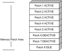
ACTIVE state
Patches in ACTIVE state are those that have run temporarily in the system and become DEACTIVE after system reboot. For the seven patches in Figure 10, if you activate the first five patches, their patch states change from DEACTIVE to ACTIVE. The patch states in the system are as shown in Figure 11.
The patches that are in ACTIVE state are in DEACTIVE state after system reboot.
Figure 11 Patches are activated
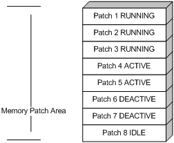
RUNNING state
After you confirm the running of the ACTIVE patches, the state of the patches changes to RUNNING and the patches are in RUNNING state after system reboot. For the five patches in Figure 11, if you confirm running the first three patches, their states change from ACTIVE to RUNNING. The patch states of the system are as shown in Figure 12.
The patches that are in RUNNING state are still in RUNNING state after system reboot.
Hotfix configuration task list
|
Task |
Remarks |
|
|
Install patches |
Use either approach. The step-by-step patch installation allows you to control the patch status. |
|
|
Uninstall patches |
Use either approach. The step-by-step patch uninstallation allows you to control the patch status. |
|
|
|
CAUTION: Make sure the version of the patch files consistent with that of the current software before loading, activating, and running the patches. |
Configuration prerequisites
Before patching the system, save the appropriate patch files to the storage media of the router with FTP or TFTP.
Patches are released according to card type. Make sure the patch files match the router model and card type.
Save the patch files to the active MPU and standby MPU so that the patches on the original standby MPU can run after an active and standby switchover. During patching, the system first searches the root directory of the storage media on the active MPU for patch files. Then it compares the patch files with the card type by the patch flag. If they match, the patches are loaded to or installed on the board.
The flag suffix is the first three characters of the version item (with the display patch information command). Table 3 describes the default patch for some card types.
Table 3 Default patches for different card types
|
Product |
Cart type |
Flag |
Default patch name |
|
SR8800 |
SR02SRP2E3 |
PATCH-M2E |
patch_m2e.bin |
|
SR02SRP1E3 |
|||
|
SR02SRP1M3 |
|||
|
SR02SRP1F3 |
PATCH-M2F |
patch_m2f.bin |
|
|
SR02SRP2F3 |
|||
|
SPE-1010 |
PATCH-LPA |
patch_lpa.bin |
|
|
SPE-1020 |
|||
|
SPE-1010-E |
PATCH-LPE |
patch_lpe.bin |
|
|
SPE-1020-E |
|||
|
IM-FW |
|||
|
SPE-1010-II |
PATCH-LPL |
patch_lpl.bin |
|
|
SPE-1020-II |
|||
|
SPE-1010-E-II |
|||
|
SPE-1020-E-II |
|||
|
IM-NAT |
PATCH-NAT |
patch_nat.bin |
|
|
IM-NAM |
PATCH-NAM |
patch_nam.bin |
|
|
IM-NAT-II |
PATCH-LNT |
patch_lnt.bin |
|
|
IM-NAM-II |
PATCH-LNS |
patch_lns.bin |
|
|
SPC-XP4L |
PATCH-LC |
patch_lc.bin |
|
|
SPC-XP2L |
|||
|
SPC-GP24L |
|||
|
SPC-GP48L |
|||
|
SPC-GT48L |
Installing a patch in one step
To install patches in one step, execute the patch install command with specifying either the directory where the patch file locates or the filename of the patch package.
After you execute the patch install command, the system displays the "Do you want to continue running patches after reboot? [Y/N]:" message. If you enter:
· y or Y: All the patches are installed, and turn to RUNNING state from IDLE. This equals execution of the commands patch location, patch load, patch active, and patch run. The patches remain in RUNNING state after system reboot.
· n or N: All the patches are installed and turn to ACTIVE state from IDLE. This equals execution of the commands patch location, patch load, and patch active. The patches turn to DEACTIVE state after system reboot.
To install a patch package, save the patch package file to the storage media of the active MPU. The standby MPU and all interface cards will load the patch file from the active MPU.
To install the patches in one step:
|
Step |
Command |
|
1. Enter system view. |
system-view |
|
2. Install the patches in one step. |
patch install { patch-location | file patch-package } |
|
|
NOTE: · The patch matches the card type and software version. · If you install a patch file by specifying the directory where the patch file locates, the patch install command will change the patch file location specified with the patch location command to the directory specified by the patch-location argument of the patch install command. · If you install a patch file by specifying the filename of the patch package, the patch install command will not change the patch file location specified with the patch location command. · To uninstall all patches in one operation, use the undo patch install command, which is the same as performing Uninstalling a patch step-by-step. |
Installing a patch step-by-step
Step-by-step patch installation enables you to control the patch status during the patch installation process.
Step-by-step patch installation task list
|
Task |
Remarks |
|
Optional. To install a patch package, skip this step. |
|
|
Required. |
|
|
Required. |
|
|
Optional. |
Configuring the patch file location
If you save the patch files to other storage media except the flash on the router, you need to specify the directory where the patch files locate with the patch-file argument. Then the system loads the appropriate patch files from the specified directory.
To configure the path file location:
|
Step |
Command |
Remarks |
|
3. Enter system view. |
system-view |
N/A |
|
4. Configure the path to the source patch files. |
patch location patch-file |
Optional. flash: by default. |
|
|
NOTE: · The directory specified by the patch-file argument must exist on both the active MPU and standby MPU. If the standby MPU does not have such directory, the system cannot locate the patch files on the original standby MPU after an active and standby switchover. · If you install a patch file by specifying the directory where the patch file locates, after the patch install command is executed, the system automatically changes patch file location specified with the patch location command to the directory specified by the patch-location argument of the patch install command. For example, if you execute the patch location xxx command and then the patch install yyy command, the patch file location automatically changes from xxx to yyy. |
Loading a patch file
Loading the right patch files is the basis of other hotfixing operations.
· If you install a patch from a patch file, the system loads a patch file from the Flash by default. If the system cannot find the patch file on the Flash, it tries to load the patch file from the CF card.
· If you install a patch from a patch package, the system finds the correct patch file in the patch package file and loads the patch file.
|
|
CAUTION: · Set the file transfer mode to binary mode before using FTP or TFTP to upload or download patch files to or from the flash of the router. Otherwise, patch file cannot be parsed properly. · To hotfix a router with active MPU and standby MPU s, make sure that the patch files on the two boards are the same. Otherwise, the router cannot backup the patch states, resulting in patch state loss. |
To load a patch file:
|
Step |
Command |
|
1. Enter system view. |
system-view |
|
2. Load the patch file on the storage medium to the memory patch area. |
patch load slot slot-number [ file patch-package ] |
Activating patches
After you activate a patch, the patch takes effect and is in the test-run stage. After the router is reset or rebooted, the patch becomes invalid.
If you find that an ACTIVE patch is of some problem, you can reboot the router to deactivate the patch, so as to avoid a series of running faults resulting from patch error.
To activate patches:
|
Step |
Command |
|
1. Enter system view. |
system-view |
|
2. Activate the specified patches. |
patch active [ patch-number ] slot slot-number |
Confirm running patches
After you confirm that the installed patch is running, the patch state changes to RUNNING, and the patch is in the normal running stage. After the router is reset or rebooted, the patch is still valid.
To confirm the running of the patches:
|
Step |
Command |
|
1. Enter system view. |
system-view |
|
2. Confirm the running of the specified patches. |
patch run [ patch-number ] [ slot slot-number ] |
|
|
NOTE: This operation is applicable to patches in ACTIVE state only. |
Uninstalling all patches in one step
To uninstall patches from all the cards and OAM CPU in one step, use the undo patch install command. The patches then turn to IDLE state. This equals the execution of the commands patch deactive and patch delete on each card.
To uninstall all patches in one step:
|
Step |
Command |
Remarks |
|
1. Enter system view. |
system-view |
N/A |
|
2. Uninstall all patches in one step. |
undo patch install |
Deactivates and deletes all the patches. |
Uninstalling a patch step-by-step
Step-by-step patch uninstallation task list
|
Task |
Remarks |
|
Required |
|
|
Required |
Stopping patches
When you deactivate a patch, the patch state becomes DEACTIVE, and the system runs in the way before it is installed with the patch.
To deactivate patches:
|
Step |
Command |
|
1. Enter system view. |
system-view |
|
2. Stop running the specified patches. |
patch deactive [ patch-number ] slot slot-number |
Deleting patches
When a patch is deleted, the system runs in the way before it is installed with the patch.
To delete patches:
|
Step |
Command |
|
1. Enter system view. |
system-view |
|
2. Delete the specified patches from the memory patch area. |
patch delete [ patch-number ] slot slot-number |
Upgrading clock card
You can use the clock card program saved on the storage medium to upgrade the clock card on the specified MPU.
To upgrade a clock card:
|
Task |
Command |
Remarks |
|
Upgrade the clock card. |
update clockmcu slot slotnumber file filename |
Available in user view |
Upgrading card logic
To upgrade the logic of the specified card:
|
Task |
Command |
Remarks |
|
Upgrade the logic of the specified card. |
logic update file filename slot slot-number { board | subcard } |
Available in user view. |
|
|
NOTE: If you plug in a line card during upgrading of a logic, you have to wait a comparatively long time for the router to power on this line card. |
Displaying and maintaining software upgrade configuration
|
Task |
Command |
Remarks |
|
Display information of the boot file. |
display boot-loader [ slot slot-number ] [ | { begin | exclude | include } regular-expression ] |
Available in any view |
|
Display information about the patch package. |
display patch [ | { begin | exclude | include } regular-expression ] |
Available in any view |
|
Display the patch information. |
display patch information [ | { begin | exclude | include } regular-expression ] |
Available in any view |
Software upgrade configuration examples
Remote upgrade configuration example
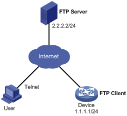
Network requirements
As shown in Figure 13, the router (Device) serves as the FTP client. The SR8800.app application program and the LPUBTR.app BootWare program are both saved in the SR8800 directory of the FTP server. The device and the FTP server can reach each other, and the PC and device can reach each other.
Upgrade the software version and Boot ROM version of the device through remote operations.
Configuration procedure
1. Configure FTP server (the configurations may vary with different types of servers)
# Enable the FTP server.
<FTP-Server> system-view
[FTP-Server] ftp server enable
# Set the FTP username to aaa and the password to hello.
[FTP-Server] local-user aaa
[FTP-Server-luser-aaa] password cipher hello
# Configure the user to have read-write permissions on the aaa directory.
[FTP-Server-luser-aaa] service-type ftp
[FTP-Server-luser-aaa] level 3
[FTP-Server-luser-aaa] authorization-attribute work-directory flash:/
2. Configure Device
|
|
CAUTION: If the size of the Flash memory on the router is not large enough, delete the original application programs from the Flash before downloading. |
# Enter the following command in the user view to log in to the FTP server.
<Device> ftp 2.2.2.2
Trying ...
Press CTRL+K to abort
Connected to 2.2.2.2.
220 WFTPD 2.0 service (by Texas Imperial Software) ready for new user
User(2.2.2.2:(none)): aaa
331 Give me your password, please
Password:
230 Logged in successfully
[ftp]
# Download the SR8800.app and LPUBTR.app files from the FTP server to the Flash memory of Device.
[ftp] get SR8800.app
[ftp] get LPUBTR.app
# Clear the FTP connection and return to the user view.
[ftp] bye
<Device>
# Upgrade the BootWare file of the MPU using the file downloaded through FTP.
<Device> bootrom update file LPUBTR.app slot 0
# Specify the application program for the next boot on MPU 0.
<Device> boot-loader file SR8800.app slot 0 main
# When the MPUs of the router work in the active/standby mode, you need to upgrade the program of the standby MPU and specify it as the application program for the next boot. If the standby MPU is in slot 1, the command is as follows:
<Device> boot-loader file slot1#flash:/SR8800.app slot 1 main
# Reboot the router. The application program is upgraded now.
<Device> reboot
Hotfix configuration example
Network requirements
As shown in Figure 14, Device is using software soft-version1. The latest patches are released to fix the defects in version 1, and an upgrading is required. The patch_m2e.bin and patch_lpe.bin patch files are saved in the aaa directory of the FTP server. Device and the FTP server can reach each other.
Hotfix the software on the device.
Configuration procedure
1. Configure FTP server (the configuration varies depending on server type)
# Enable FTP server.
<FTP-Server> system-view
[FTP-Server] ftp server enable
# Configure an FTP user with the name aaa and password hello.
[FTP-Server] local-user aaa
[FTP-Server-luser-aaa] password cipher hello
# Assign read-write rights for the FTP user aaa.
[FTP-Server-luser-aaa] service-type ftp
[FTP-Server-luser-aaa] authorization-attribute work-directory flash:/aaa
2. Configure Device
|
|
CAUTION: Make sure the free flash space of the device is big enough to store the patches. |
# Before upgrading the software, use the save command to save the current system configuration. (Details not shown)
# Log in to the FTP server. Note that the command output varies depending on server type.
<Device> ftp 2.2.2.2
Trying 2.2.2.2 ...
Press CTRL+K to abort
Connected to 2.2.2.2.
220 WFTPD 2.0 service (by Texas Imperial Software) ready for new user
User(2.2.2.2:(none)):aaa
331 Give me your password, please
Password:
230 Logged in successfully
[ftp]
# Download the patch_m2e.bin and patch_lpe.bin files from FTP Server.
[ftp] binary
[ftp] get patch_m2e.bin
[ftp] get patch_lpe.bin
[ftp] bye
<Device>
# Copy the patch files to the root directory of the standby MPU in slot 1.
<Device> copy patch_m2e.bin slot1#flash:/
<Device> copy patch_lpe.bin slot1#flash:/
# Install the patch.
<Device> system-view
[Device] patch install flash:
Patches will be installed. Continue? [Y/N]:y
Do you want to continue running patches after reboot? [Y/N]:y
Installing patches........
%Aug 8 11:15:30:607 2008 Sysname MEM/4/WARNING:
Patch load completed for slot 0.
%Aug 8 11:15:30:707 2008 Sysname MEM/4/WARNING:
Patch load completed for slot 1.
%Aug 8 11:15:30:807 2008 Sysname MEM/4/WARNING:
Patch load completed for slot 3.
%Aug 8 11:15:30:817 2008 Sysname MEM/4/WARNING:
Patch load completed for slot 3.1
Installation completed, and patches will continue to run after reboot.
