- Table of Contents
- Related Documents
-
| Title | Size | Download |
|---|---|---|
| 07-Device Management Configuration | 245.25 KB |
Contents
Displaying device configuration
Enabling displaying copyright information
Configuring the exception handling method
Configuring system working mode
Scheduling a job in the non-modular approach
Scheduling a job in the modular approach·
Scheduled job configuration example
Configuring the port status detection timer
Configuring temperature alarm thresholds for a card
Starting and stopping power supply to a card
Enabling the power alarm monitoring function
Configuring in-service hardware failure diagnosis
Configuring the load mode for the active MPU and standby MPU
Configuring the size of the buffer shared by all interfaces on an interface card
Clearing unused 16-bit interface indexes
Enabling automatic forwarding path check
Configuring the working mode of an interface subcard
Verifying and diagnosing transceiver modules
Introduction to transceiver modules
Verifying pluggable transceivers
Diagnosing transceiver modules
Displaying and maintaining device management
Device management overview
Device management includes monitoring the operating status of devices and configuring their running parameters.
|
|
NOTE: Storage media include Flash and compact Flash (CF). Flash is exemplified in this document. In this document, SPC cards refer to the cards with silkscreen staring with SPC, for example, SPC-GT48L, and SPE cards refer to the cards with silkscreen staring with SPE, for example, SPE-1020-E-II. File names in this document comply with the following rules: · Path + file name (namely, a full file name): File on a specified path. A full file name consists of 1 to 135 characters. · “File name” (namely, only a file name without a path): File on the current working path. The file name without a path consists of 1 to 91 characters. |
Displaying device configuration
To avoid duplicate configuration, use the display commands to view the current configuration of the router before configuring the router. The configurations of a router include:
· Current configuration—The running configuration on the router. Unless otherwise noted (such as a command that takes effect after the router reboots), the current configuration is not effective after the router reboots.
· Saved configuration—Configuration saved in the configuration file, which helps to restore configurations conveniently.
To display device configurations:
|
Task |
Command |
Remarks |
|
Display the factory default configuration of the router. |
display default-configuration [ | { begin | exclude | include } regular-expression ] |
Available in any view |
|
Display the current configuration of the router. |
display current-configuration [ [ configuration [ configuration ] | interface [ interface-type ] [ interface-number ] ] [ by-linenum ] [ | { begin | exclude | include } regular-expression ] ] [ | { begin | exclude | include } regular-expression ] |
Available in any view |
|
Display the saved configuration, or, in other words, the content of the configuration file. |
more file-url To display the configuration file used at the next startup, use this command: display saved-configuration [ by-linenum ] |
The more command is available in user view. The display saved-configuration command is available in any view. |
|
|
NOTE: For more information about the more, display default-configuration, display current-configuration, and display saved-configuration commands, see the chapters “Managing files” and “Managing configuration files.” |
Configuring the device name
A device name identifies a device in a network and works as the user view prompt at the CLI. For example, if the device name is Sysname, the user view prompt is <Sysname>.
To configure the device name:
|
Step |
Command |
Remarks |
|
1. Enter system view. |
system-view |
N/A |
|
2. Configure the device name. |
sysname sysname |
Optional H3C by default |
Changing the system time
Configuring the system time
You must synchronize your device with a trusted time source by using NTP or changing the system time before you run it on the network. Network management depends on an accurate system time setting, because the timestamps of system messages and logs use the system time.
In a small-sized network, you can manually set the system time of each device.
Configuration guidelines
You can change the system time by configuring the relative time, time zone, and daylight saving time. The configuration result depends on their configuration order (see Table 1). In the first column of this table, 1 represents the clock datetime command, 2 represents the clock timezone command, and 3 represents the clock summer-time command. To verify the system time setting, use the display clock command. This table assumes that the original system time is 2005/1/1 1:00:00.
Table 1 System time configuration results
|
Command |
Effective system time |
Configuration example |
System time |
|
1 |
date-time |
01:00:00 UTC Mon 01/01/2007 |
|
|
2 |
Original system time ± zone-offset |
02:00:00 zone-time Sat 01/01/2005 |
|
|
1, 2 |
date-time ± zone-offset |
03:00:00 zone-time Fri 02/02/2007 |
|
|
2, 1 |
date-time |
03:00:00 zone-time Sat 03/03/2007 |
|
|
3 |
The original system time outside the daylight saving time range: The system time does not change until it falls into the daylight saving time range. |
01:00:00 UTC Sat 01/01/2005 |
|
|
The original system time in the daylight saving time range: The system time increases by summer-offset. |
03:00:00 ss Sat 01/01/2005 NOTE: If the original system time plus summer-offset is beyond the daylight saving time range, the original system time does not change. After you disable the daylight saving setting, the system time automatically decreases by summer-offset. |
||
|
1, 3 |
date-time outside the daylight saving time range: date-time |
01:00:00 UTC Mon 01/01/2007 |
|
|
date-time in the daylight saving time range: date-time + summer-offset |
10:00:00 ss Mon 01/01/2007 NOTE: If the date-time plus summer-offset is outside the daylight saving time range, the system time equals date-time. After you disable the daylight saving setting, the system time automatically decreases by summer-offset. |
||
|
3, 1 (date-time outside the daylight saving time range) |
date-time |
01:00:00 UTC Tue 01/01/2008 |
|
|
3, 1 (date-time in the daylight saving time range) |
date-time – summer-offset outside the daylight saving time range: date-time – summer-offset |
23:30:00 UTC Sun 12/31/2006 |
|
|
date-time – summer-offset in the daylight saving time range: date-time |
03:00:00 ss Mon 01/01/2007 |
||
|
2, 3 or 3, 2 |
Original system clock ± zone-offset outside the daylight saving time range: Original system clock ± zone-offset |
02:00:00 zone-time Sat 01/01/2005 |
|
|
Original system clock ± zone-offset outside the daylight saving time range: Original system clock ± zone-offset + summer-offset |
System clock configured: 04:00:00 ss Sat 01/01/2005 |
||
|
1, 2 , 3 or 1, 3, 2 |
date-time ± zone-offset outside the daylight saving time range: date-time ± zone-offset |
02:00:00 zone-time Mon 01/01/2007 |
|
|
date-time ± zone-offset outside the daylight saving time range: date-time ± zone-offset + summer-offset |
04:00:00 ss Mon 01/01/2007 |
||
|
2, 3, 1 or 3, 2, 1 |
date-time outside the daylight saving time range: date-time |
01:00:00 zone-time Mon 01/01/2007 |
|
|
date-time in the daylight saving time range, but date-time – summer-offset outside the summer-time range: date-time – summer-offset |
23:30:00 zone-time Mon 12/31/2007 |
||
|
Both date-time and date-time – summer-offset in the daylight saving time range: date-time |
03:00:00 ss Tue 01/01/2008 |
Configuration procedure
To configure the system time:
|
Step |
Command |
Remarks |
|
1. Set the system time and date. |
clock datetime time date |
Optional. Available in user view. |
|
2. Enter system view. |
system-view |
N/A |
|
3. Set the time zone. |
clock timezone zone-name { add | minus } zone-offset |
Optional. Universal time coordinated (UTC) time zone by default. |
|
4. Set a daylight saving time scheme. |
·
Set a non-recurring
scheme: · Set a recurring scheme: |
Optional. Use either command. By default, daylight saving time is disabled, and the UTC time zone applies. |
Enabling displaying copyright information
The device by default displays the copyright statement when a Telnet or SSH user logs in, or when a console user quits user view. You can disable or enable the function as needed. The following is a sample copyright statement:
**************************************************************************
* Copyright (c) 2004-2009 Hangzhou H3C Tech. Co., Ltd. All rights reserved.*
* Without the owner's prior written consent, *
* no decompiling or reverse-engineering shall be allowed. * **************************************************************************
To enable displaying copyright information:
|
Step |
Command |
Remarks |
|
1. Enter system view. |
system-view |
N/A |
|
2. Enable displaying copyright information. |
copyright-info enable |
Optional Enabled by default |
Configuring banners
Introduction to banners
Banners are messages that the system displays when a user connects to the device to perform login authentication, and start interactive configuration.
Banner types
The system supports the following types of banners:
· Legal banner appears after the system displays the copyright or license statement for a user attempting to log in. To continue authentication or login, the user must enter Y or press Enter. To quit the process, the user must enter N. Y and N are case-insensitive.
· Message of the Day (MOTD) banner displays the greeting message, and appears after the legal banner and before the login banner. Support for this banner depends on the device model.
· Login banner appears only when password or scheme login authentication has been configured.
· Incoming banner appears for Modem dial-in users and the shell banner appears for users that use any other access method to access the CLI.
Message input modes
The system supports single-line input and multiple-line input for configuring a banner.
· Single-line input
In single-line input mode, all banner information comes after the command keywords in the same line. The start and end characters of the input text must be the same but are not part of the banner information. The input text, together with the command keywords, cannot exceed 510 characters. In this mode, do not press Enter after typing the banner information. For example, to configure a banner like “Have a nice day.”, use the following command:
<System> system-view
[System] header shell %Have a nice day.%
· Multiple-line input
In multiple-line input mode, you can press Enter to separate the banner information in multiple lines. In this case, up to 2000 characters can be typed.
Use one of the following methods to implement multi-line input mode:
? Method I—Press the Enter key after the command keywords, type the banner information, and finish with the % character. The % character is not part of the banner information. For example, to configure a banner like “Have a nice day. Please input the Password!”, use the following commands:
<System> system-view
[System] header shell
Please input banner content, and quit with the character '%'.――System prompt
Have a nice day.
Please input the Password!%
? Method II—Type a character after the command keywords at the first line, and press Enter. Type the banner information, and finish with the character you typed at the first line. The start character and the end character are not part of the banner information. For example, to configure a banner like “Have a nice day. Please input the Password!”, use the following commands:
<System> system-view
[System] header shell A
Please input banner content, and quit with the character 'A'.――System prompt
Have a nice day.
Please input the Password!A
? Method III—Type multiple characters after the command keywords at the first line (with the first and last characters being different), and press the Enter key. Type the banner information, and finish with the first character you typed at the first line. The first input character at the first line and the end character are not part of the banner information. For example, to configure a banner like “Have a nice day. Please input the Password!”, use the following commands:
<System> system-view
[System] header shell AHave a nice day.
Please input banner content, and quit with the character 'A'.――System prompt
Please input the Password!A
Configuring procedure
To configure banners:
|
Step |
Command |
Remarks |
|
1. Enter system view. |
system-view |
N/A |
|
2. Configure the incoming banner. |
header incoming text |
Optional |
|
3. Configure the login banner. |
header login text |
Optional |
|
4. Configure the legal banner. |
header legal text |
Optional |
|
5. Configure the shell banner. |
header shell text |
Optional |
|
6. Configure the MOTD banner. |
header motd text |
Optional |
Configuring the exception handling method
You can configure the device to handle system exceptions in one of the following methods:
· reboot— The device automatically reboots to recover from the error condition.
· maintain—The device stays in the error condition so you can collect complete data, including error messages, for diagnosis. In this approach, you must manually reboot the device.
To configure the exception handling method:
|
Step |
Command |
Remarks |
|
1. Enter system view. |
system-view |
N/A |
|
2. Configure the exception handling method on the active main processing unit (MPU) and the standby MPUs. |
system-failure { maintain | reboot } |
Optional By default, the active MPU and the standby MPUs adopt the reboot method to handle exceptions. |
|
|
NOTE: · With this command configured, both the active MPU and the standby MPU adopt the same method to handle exceptions. The device always reboots an interface card or the auxiliary CPU system when an exception occurs to them. · The exception handling method is effective to the failed card only, and does not influence the functions of other cards. |
Rebooting the router
You can reboot the router in one of the following ways to recover from an error condition:
· Reboot the router immediately at the CLI.
· At the CLI, schedule a reboot to occur at a specific time and date or after a delay.
· Power off and then re-power on the router. This method might cause data loss, and is the least preferred method.
Reboot at the CLI enables easy remote device maintenance.
|
|
CAUTION: · Device reboot can interrupt network services. · To avoid data loss, use the save command to save the current configuration before a reboot. · Use the display startup and display boot-loader commands to check that you have correctly set the startup configuration file and the main system software image file. If the main system software image file has been corrupted or does not exist, the device cannot reboot. You must re-specify a main system software image file, or power off the device and then power it on so the system can reboot with the backup system software image file. |
To reboot the router immediately at the CLI, perform the following command in user view:
|
Task |
Command |
Remarks |
|
Reboot a card or the whole system. |
reboot [ slot slot-number ] |
Optional. If no card is specified, the command reboots the whole device. |
To schedule a device reboot, perform one of the following commands in user view :
|
Task |
Command |
Remarks |
|
Schedule a reboot. |
·
Schedule a reboot to occur at a specific time
and date: ·
Schedule a reboot to occur after a delay: |
Use either approach. The scheduled reboot function is disabled by default. Changing any clock setting can cancel the reboot schedule. |
|
|
NOTE: · If the device has only one MPU, rebooting the MPU causes the device to reboot. If the device has two MPUs, rebooting the active MPU causes the active MPU to reboot and an active/standby switchover. You cannot use the reboot command to reboots a standby MPU. To reboot a standby MPU, use the slave restart command (see High Availability Command Reference). · For data security, if you are performing file operations at the reboot time, the system does not reboot. |
Configuring system working mode
A working mode defines a kind of assignment of hardware resources. You can change the system working mode to suit different services. The router may work in any of the following three working modes:
· hybrid—In this mode, both the SPC and SPE cards can work normally.
· spc—In this mode, only the SPC cards (for example, SPC-GT48L) can work normally.
· spe—In this mode, only the SPE cards (for example, SPE-1020-E-II) can work normally.
To configure the system working mode:
|
Step |
Command |
Remarks |
|
1. Enter system view. |
system-view |
N/A |
|
2. Configure the system working mode. |
system working mode { hybrid | spc | spe } |
Hybrid by default |
|
|
NOTE: A reboot is required after you change the system working mode to make your changes take effect. |
Scheduling jobs
You can schedule a job to automatically run a command or a set of commands without administrative interference. The commands in a job are polled every minute. When the scheduled time for a command is reached, the job automatically executes the command. If a confirmation is required while the command is running, the system automatically enters Y or Yes. If characters are required, the system automatically enters a default character string or an empty character string when no default character string is available.
Job configuration approaches
You can configure jobs in a non-modular or modular approach. Use the non-modular approach for a one-time command execution and use non-modular approach for complex maintenance work.
Table 2 A comparison of non-modular and modular approaches
|
Comparison item |
||
|
Configuration method |
Configure all elements in one command |
Separate job, view, and time settings |
|
Can multiple jobs be configured? |
No |
Yes |
|
Can a job have multiple commands? |
No If you use the schedule job command repeatedly, only the last configuration takes effect. |
Yes You can use the time command in job view to configure commands to be executed at different time points. |
|
Supported views |
User view and system view. In the schedule job command, shell represents user view, and system represents system view. |
All views. In the time command, monitor represents user view. |
|
Supported commands |
Commands in user view and system view |
Commands in all views |
|
Can a job be repeatedly executed? |
No |
Yes |
|
Can a job be saved? |
No |
Yes |
|
Can a job be backed up to the standby MPU? |
No |
Yes |
Configuration guidelines
· To have a job successfully run a command, check that the specified view and command are valid. The system does not verify their validity.
· The configuration interface, view, and user status that you have before job execution restores even if the job has run a command that changes the user interface (for example, telnet, ftp, and ssh2), the view (for example, system-view and quit), or the user status (for example, super).
· The jobs run in the background without displaying any messages except log, trap and debugging messages.
· In the modular approach:
? Every job can have only one view and up to 10 commands. If you specify multiple views, the one specified last takes effect.
? Input a view name in its complete form. Most commonly used view names include monitor for user view, system for system view, GigabitEthernetx/x/x for Ethernet interface view, and Vlan-interfacex for VLAN interface view.
? The time ID (time-id) must be unique in a job. If two time and command bindings have the same time ID, the one configured last takes effect.
Scheduling a job in the non-modular approach
To schedule a job, perform one of the following commands in user view:
|
Task |
Command |
Remarks |
|
Schedule a job. |
Schedule a job to run a command at a
specific time: Schedule a job to run a command after a
delay: |
Use either command. NOTE: · If you execute the schedule job command repeatedly, the last configuration takes effect. · Changing any clock setting can cancel the job set by using the schedule job command. |
Scheduling a job in the modular approach
To configure a scheduled job:
|
Step |
Command |
Remarks |
|
1. Enter system view. |
system-view |
N/A |
|
2. Create a job and enter job view. |
job job-name |
N/A |
|
3. Specify the view in which the commands in the job run. |
view view-name |
You can specify only one view for a job. The job executes all commands in the specified view. |
|
4. Add commands to the job. |
·
Configure a command
to run at a specific time and date: ·
Configure a command
to run at a specific time: · Configure a command to run after a
delay: |
Use any of the commands. NOTE: Changing a clock setting does not affect the schedule set by using the time at or time delay command. |
Scheduled job configuration example
Network requirements
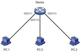
Configure scheduled jobs on the device to enable interfaces GigabitEthernet 3/1/1, GigabitEthernet 3/1/2, and GigabitEthernet 3/1/3 at 8:00 and disabled them at 18:00 on working days every week, to control the access of the PCs connected to these interfaces.
Figure 1 Network diagram
Configuration procedure
# Enter system view.
<Sysname> system-view
# Create a job named pc1, and enter its view.
[Sysname] job pc1
# Configure the job to be executed in the view of GigabitEthernet 3/1/1.
[Sysname-job-pc1] view GigabitEthernet 3/1/1
# Configure the router to enable GigabitEthernet 3/1/1 at 8:00 on working days every week.
[Sysname-job-pc1] time 1 repeating at 8:00 week-day mon tue wed thu fri command undo shutdown
# Configure the router to shut down GigabitEthernet 3/1/1 at 18:00 on working days every week.
[Sysname-job-pc1] time 2 repeating at 18:00 week-day mon tue wed thu fri command shutdown
[Sysname-job-pc1] quit
# Create a job named pc2, and enter its view.
[Sysname] job pc2
# Configure the job to be executed in the view of GigabitEthernet 3/1/2.
[Sysname-job-pc2] view GigabitEthernet 3/1/2
# Configure the router to enable GigabitEthernet 3/1/2 at 8:00 on working days every week.
[Sysname-job-pc2] time 1 repeating at 8:00 week-day mon tue wed thu fri command undo shutdown
# Configure the router to shut down GigabitEthernet 3/1/2 at 18:00 on working days every week.
[Sysname-job-pc2] time 2 repeating at 18:00 week-day mon tue wed thu fri command shutdown
[Sysname-job-pc2] quit
# Create a job named pc3, and enter its view.
[Sysname] job pc3
# Configure the job to be executed in the view of GigabitEthernet 3/1/3.
[Sysname-job-pc3] view GigabitEthernet 3/1/3
# Configure the router to enable GigabitEthernet 3/1/3 at 8:00 on working days every week.
[Sysname-job-pc3] time 1 repeating at 8:00 week-day mon tue wed thu fri command undo shutdown
# Configure the router to shut down GigabitEthernet 3/1/3 at 18:00 on working days every week.
[Sysname-job-pc3] time 2 repeating at 18:00 week-day mon tue wed thu fri command shutdown
[Sysname-job-pc3] quit
# Display information about scheduled jobs.
[Sysname] display job
Job name: pc1
Specified view: GigabitEthernet3/1/1
Time 1: Execute command undo shutdown at 08:00 Mondays Tuesdays Wednesdays Thursdays Fridays
Time 2: Execute command shutdown at 18:00 Mondays Tuesdays Wednesdays Thursdays Fridays
Job name: pc2
Specified view: GigabitEthernet3/1/2
Time 1: Execute command undo shutdown at 08:00 Mondays Tuesdays Wednesdays Thursdays Fridays
Time 2: Execute command shutdown at 18:00 Mondays Tuesdays Wednesdays Thursdays Fridays
Job name: pc3
Specified view: GigabitEthernet3/1/3
Time 1: Execute command undo shutdown at 08:00 Mondays Tuesdays Wednesdays Thursdays Fridays
Time 2: Execute command shutdown at 18:00 Mondays Tuesdays Wednesdays Thursdays Fridays
Configuring the port status detection timer
Some protocols might shut down ports under specific circumstances. For example, MSTP shuts down a BPDU guard–enabled port when the port receives a BPDU. In this case, you can set the port status detection timer. If the port is still down when the detection timer expires, the protocol module automatically cancel the shutdown action and restore the port to its original physical status.
To configure the port status detection timer:
|
Step |
Command |
Remarks |
|
1. Enter system view. |
system-view |
N/A |
|
2. Configure the port status detection timer. |
shutdown-interval time |
Optional 30 seconds by default |
Configuring temperature alarm thresholds for a card
You can set temperature alarm thresholds for a card by using the following command. When the temperature of a card exceeds the threshold, the router will generate alarm signals.
To configure temperature alarm thresholds for a card:
|
Step |
Command |
Remarks |
|
1. Enter system view. |
system-view |
N/A |
|
2. Configure temperature alarm thresholds for a card. |
temperature-limit slot slot-number hotspot sensor-number lowerlimit warninglimit [ alarmlimit ] |
Optional |
Manging power supply
Starting and stopping power supply to a card
When the power supply of the system is insufficient, the device automatically supplies power to the cards according to a specific mechanism. You can use the display power-supply command to view the power supply conditions of the router and the cards. You can also start and stop power supply to a card to adjust the available power of the system according to the actual power supply conditions.
To start or stop power supply to a card, perform the following command in user view:
|
Task |
Command |
Remarks |
|
Start or stop power supply to a card. |
power-supply { on | off } slot slot-number |
Optional. The specified card cannot be an MPU. |
Enabling the power alarm monitoring function
The power alarm monitoring function enables the device to monitor the power status. When an exception occurs to a power module or a power module is not present, the device displays the power status through the ALARM LED on the MPU. If you do not enable this function, you can only use the display alarm to check the alarms for troubleshooting.
After you enable the power alarm monitoring function, one of the following occurs:
· When the ALARM LED is steady on, an exception migh have occurred to a power module or a card. You can use the display alarm command to view detailed alarms.
· When the ALARM LED blinks, one or multiple power modules are not present.
· When the ALARM LED is off, all power modules operate normally.
To enable the power alarm monitoring function:
|
Step |
Command |
Remarks |
|
1. Enter system view. |
system-view |
N/A |
|
2. Enable the power alarm monitoring function. |
power alarm enable |
Disabled by default |
|
|
NOTE: If you enable this function and save the configuration, the ALARM LED on the MPU can display the power status even after the MPU reboots. |
Configuring in-service hardware failure diagnosis
A hardware failure may cause traffic forwarding failures and service interruption. To improve the automatic failure detection and handling capabilities of the router, you can configure in-service hardware failure diagnosis and failure protection.
The in-service hardware failure diagnosis and failure protection feature covers in-service hardware failure detection for chips, cards, and the forwarding service, and automatic fix actions taken for the detected failures.
To configure in-service hardware failure diagnosis and failure protection:
|
Step |
Command |
Remarks |
|
1. Enter system view. |
system-view |
N/A |
|
2. Enable in-service hardware failure detection and configure fix actions taken in case of hardware failures.. |
hardware-failure-detection { chip | board | forwarding } { off | warning | reset | isolate } |
The fix actions taken in case of hardware failures include: · off—Takes no action. · warning—Sends warning messages. · reset—Resets the failed card. · isolate—Shuts down the failed port, isolates the failed card, prohibits the failed card from loaded, or powers off the failed card to reduce the impact of the failure to the system. By default, the fix action taken for all hardware failures is warning. |
|
|
NOTE: · The router does not support the keywords reset and isolate. · After configuring in-service diagnosis and failure protection, you can use the display hardware-failure-detection command to check the running information of the feature. |
Configuring the load mode for the active MPU and standby MPU
The active MPU and standby MPU support the following load modes:
· load-balance—Load (processing and forwarding packets) is balanced between the active MPU and standby MPU.
· load-single—The active MPU processes and forwards packets, whereas the standby MPU only backs up data and monitors the state of the active MPU.
To configure the load mode for active MPU and standby MPU:
|
Step |
Command |
Remarks |
|
1. Enter system view. |
system-view |
N/A |
|
2. Configure the load mode for active MPU and standby MPU. |
xbar { load-balance | load-single } |
Optional. The active MPU and standby MPU work in load-single mode by default. |
|
|
CAUTION: The load-balance mode is valid only when both the active MPU and standby MPU are in their slots. If only the active MPU is available, the active MPU automatically switches to the load-single mode after the load-balance mode is configured. |
Configuring the size of the buffer shared by all interfaces on an interface card
An interface card uses a buffer with a fixed size to buffer the packets received and sent. A buffer comprises multiple storage units. It is divided into two areas: fixed buffer and shared buffer. The fixed buffer is allocated to the interfaces according to a certain algorithm, and the shared buffer is shared by all interfaces. When the traffic of an interface becomes heavy, and the fixed buffer cannot provide sufficient memory, the shared buffer provides temporary memory for the interface.
By default, the fixed buffer and the shared buffer contain a fixed number of storage units. You can configure the number of storage units in the shared buffer as needed. Because the total number of storage units in a buffer is fixed, the number of storage units in the fixed buffer will change after your configuration. You can tune the shared buffer area depending on traffic patterns. If transient large traffic bursts occur on some interfaces, you can expand the shared buffer to accommodate the bursts to prevent traffic loss. If transient small traffic bursts often occur on the interfaces, you can decrease the shared buffer so that each port can get more dedicated buffer memory.
To set the size in blocks of the receive or transmit buffer shared by all interfaces on an interface card:
|
Step |
Command |
Remarks |
|
1. Enter system view. |
system-view |
Available in user view |
|
2. Set the size of the receive or transmit buffer shared by all interfaces on an interface card. |
buffer-manage { ingress | egress } slot slot-number share-size size-value |
Optional. By default, the size of the shared receive buffer is 1024 blocks, and that of the shared transmit buffer is 4608 blocks. |
Clearing unused 16-bit interface indexes
The device must maintain persistent 16-bit interface indexes and keep one interface index match one interface name for network management. After deleting a logical interface, the device retains its 16-bit interface index so the same index can be assigned to the interface at interface re-creation.
To avoid index depletion causing interface creation failures, you can clear all 16-bit indexes that have been assigned but not in use. The operation does not affect the interface indexes of the interfaces that have been created but the indexes assigned to re-recreated interfaces might change.
To clear unused 16-bit interface indexes, perform one of the following commands in user view:
|
Task |
Command |
|
Clear unused 16-bit interface indexes. |
reset unused porttag |
|
|
CAUTION: A confirmation is required when you execute this command. The command will not run if you fail to make a confirmation within 30 seconds or enter N to cancel the operation. |
Enabling automatic forwarding path check
When the router is operating, traffic forwarding exceptions might occur due to hardware failures or other reasons. You can enable automatic forwarding path check so that the router gives prompts when a forwarding exception occurs. According to the prompts, you can troubleshoot the problem.
To enable automatic forwarding path check:
|
Step |
Command |
Remarks |
|
1. Enter system view. |
system-view |
N/A |
|
2. Enable automatic forwarding path check. |
forward-path check { enable | disable } |
Enabled by default |
Above the configuration, if a forwarding exception occurs, the router gives prompts, for example:
%Aug 20 14:55:54:973 2010 H3C DIAG/3/ERROR: -Slot=8; Forwarding fault: slot 5 to slot 8
%Aug 20 14:55:55:084 2010 H3C DIAG/3/ERROR: -Slot=6; Forwarding fault: slot 6 to slot 6
The output shows that a forwarding exception exists between the cards in slot 8 and slot 5, and an exception in internal data forwarding exists on the card in slot 6.
Configuring the working mode of an interface subcard
The router supports multiple interface subcard types. Some subcards have only one function, some have multifunctional modules, and some other subcards can be configured with different working modes. The router supports the following switching mode:
· E1/T1—Supports the E1/T1 switch of the entire interface subcard. When this interface subcard works in E1 mode, all the interfaces on the interface subcard can receive, send and process E1 data flows, and provide CE1 access; when this interface subcard works in T1 mode, all the interfaces on the interface subcard can receive, send and process T1 data flows, and provide CT1 access.
· CPOS 155 Mbps (E/T)—Supports the E/T switch of the entire interface subcard. When this interface subcard works in E mode, all the interfaces on this interface subcard can receive, send and process E3 high speed data flows, and provide E3 access for non-framed data flows at a speed of 34.368 Mbps, and E3 access for framed data flows at a speed of 34.01 Mbps. All the interfaces on the interface subcard can also receive, send and process E1 data flows, and provide CE1 access, thus implementing the ISDN PRI function. When this interface subcard works in T mode, all the interfaces on this interface subcard can receive, send and process T3 high speed data flows, and provide T3 access for non-framed data flows at a speed of 44.736 Mbps and T3 access for framed data flows at a speed of 44.21 Mbps. All the interfaces on the interface subcard can also receive, send and process T1 data flows, and provide CT1 access, thus implementing the ISDN PRI function.
To configure the working mode of an interface subcard:
|
Step |
Command |
Remarks |
|
1. Enter system view. |
system-view |
N/A |
|
2. Set the working mode of an interface subcard. |
card-mode slot slot-number subslot subslot-number mode-name |
Optional. The mode-name argument might take the value of e or t. |
|
|
CAUTION: · After a mode switching, you must restart the router to make the newly configured working mode take effect. · Only interface subcards PIC-CL1G8L, PIC-CL2G8L, PIC-ET8G8L, PIC-ET32G2L, PIC-CLF4G8L, and PIC-CLF2G8L support switching of working modes. |
Verifying and diagnosing transceiver modules
Introduction to transceiver modules
Table 3 lists the commonly used transceiver modules. They can be further divided into optical transceiver modules and electrical transceiver modules based on transmission medium.
Table 3 Commonly used pluggable transceivers
|
Transceiver type |
Application environment |
Whether can be an optical transceiver |
Whether can be an electrical transceiver |
|
SFP (Small Form-factor Pluggable) |
Generally used for 100M/1000M Ethernet interfaces or POS 155M/622M/2.5G interfaces |
Yes |
Yes |
|
XFP (10-Gigabit small Form-factor Pluggable) |
Generally used for 10G Ethernet interfaces |
Yes |
No |
Verifying pluggable transceivers
You can verify the genuineness of a transceiver module in the following ways:
· Display the key parameters of a transceiver module, including its transceiver type, connector type, central wavelength of the transmit laser, transfer distance and vendor name.
· Display its electronic label. The electronic label is a profile of the transceiver module and contains the permanent configuration including the serial number, manufacturing date, and vendor name. The data is written to the storage component during debugging or testing.
To verify transceiver modules, perform the following commands in any view:
|
Task |
Command |
|
Display key parameters of the transceiver modules. |
display transceiver { controller [ controller-type controller-number ] | interface [ interface-type interface-number ] ] } [ | { begin | exclude | include } regular-expression ] |
|
Display transceiver modules’ electrical label information. |
display transceiver manuinfo { controller [ controller-type controller-number ] | interface [ interface-type interface-number ] ] } [ | { begin | exclude | include } regular-expression ] |
|
|
NOTE: The display transceiver manuinfo command cannot display information for some transceiver modules. |
Diagnosing transceiver modules
The device provides the alarm function and digital diagnosis function for transceiver modules. When a transceiver module fails or inappropriately work, you can check for alarms present on the transceiver module to identify the fault source or examine the key parameters monitored by the digital diagnosis function, including the temperature, voltage, laser bias current, TX power, and RX power.
To diagnose transceiver modules, perform the following commands in any view:
|
Task |
Command |
|
Display alarms present on transceiver modules. |
display transceiver alarm { controller [ controller-type controller-number ] | interface [ interface-type interface-number ] ] } [ | { begin | exclude | include } regular-expression ] |
|
Display the present measured values of the digital diagnosis parameters for transceiver modules. |
display transceiver diagnosis { controller [ controller-type controller-number ] | interface [ interface-type interface-number ] ] } [ | { begin | exclude | include } regular-expression ] |
|
|
NOTE: The display transceiver diagnosis command cannot display information for some transceiver modules. |
Displaying and maintaining device management
|
Task |
Command |
Remarks |
|
Display alarm information. |
display alarm [ slot slot-number ] [ | { begin | exclude | include } regular-expression ] |
Available in any view |
|
Display system version information. |
display version [ | { begin | exclude | include } regular-expression ] |
Available in any view |
|
Display the system time and date. |
display clock [ | { begin | exclude | include } regular-expression ] |
Available in any view |
|
Display clipboard information. |
display clipboard [ | { begin | exclude | include } regular-expression ] |
Available in any view |
|
Display or save running status data for multiple feature modules. |
display diagnostic-information [ | { begin | exclude | include } regular-expression ] |
Available in any view |
|
Display shared buffer configuration. |
display buffer-manage configuration [ slot slot-number ] [ | { begin | exclude | include } regular-expression ] |
Available in any view |
|
Display CPU usage statistics. |
display cpu-usage [ slot slot-number [ cpu cpu-number ] ] [ | { begin | exclude | include } regular-expression ] display cpu-usage entry-number [ offset ] [ verbose ] [ slot slot-number ] [ from-device ] [ | { begin | exclude | include } regular-expression ] |
Available in any view |
|
Display historical CPU usage statistics in charts. |
display cpu-usage history [ task task-id ] [ slot slot-number [ cpu cpu-number ] [ | { begin | exclude | include } regular-expression ] |
Available in any view |
|
Display device information. |
display device [ cf-card ] [ [ slot slot-number [ subslot subslot-number ] ] | verbose ] [ | { begin | exclude | include } regular-expression ] |
Available in any view |
|
Display the electronic label data for the router. |
display device manuinfo [ slot slot-number [ subslot slot-number ] ] [ | { begin | exclude | include } regular-expression ] |
Available in any view |
|
Display the electronic label data for the specified power monitor module. |
display device manuinfo power-monitor pmu-id [ | { begin | exclude | include } regular-expression ] |
Available in any view |
|
Display device temperature information. |
display environment [ slot slot-number ] [ | { begin | exclude | include } regular-expression ] |
Available in any view |
|
Display the operating states of fans. |
display fan [ fan-id ] [ | { begin | exclude | include } regular-expression ] |
Available in any view |
|
Display hardware failure detection and fix operation records. |
display hardware-failure-detection [ | { begin | exclude | include } regular-expression ] |
Available in any view |
|
Display memory usage statistics. |
display memory [ slot slot-number [ cpu cpu-number ] ] [ | { begin | exclude | include } regular-expression ] |
Available in any view |
|
Display power supply information. |
display power-supply [ verbose ] [ | { begin | exclude | include } regular-expression ] |
Available in any view |
|
Display the configuration of the job configured by using the schedule job command. |
display schedule job [ | { begin | exclude | include } regular-expression ] |
Available in any view |
|
Display the reboot schedule. |
display schedule reboot [ | { begin | exclude | include } regular-expression ] |
Available in any view |
|
Display the load mode of the current active and standby cards. |
display xbar [ | { begin | exclude | include } regular-expression ] |
Available in any view |
|
Display the system working mode. |
display system working mode [ | { begin | exclude | include } regular-expression ] |
Available in any view |
|
Display the exception handling method for the active MPU and standby MPU. |
display system-failure [ | { begin | exclude | include } regular-expression ] |
Available in any view |
|
Display the configuration of jobs configured by using the job command. |
display job [ job-name ] [ | { begin | exclude | include } regular-expression ] |
Available in any view |
