- Table of Contents
- Related Documents
-
| Title | Size | Download |
|---|---|---|
| 02-Login Management Configuration | 418.24 KB |
Contents
Logging in through the console port
Logging in through the AUX port
Setting up a configuration environment
Logging in to the router from an SSH client
Configuring the SSH client to log in to the SSH server
Logging in through the AUX port by using modems
Configurations on the administrator side
Setting up a configuration environment
User interface configuration task list
Configuring asynchronous serial interface attributes
Configuring terminal attributes
Configuring a command to be automatically executed
Configuring user privilege level under a user interface
Configuring access control on VTY user interfaces
Configuring supported protocols on VTY user interfaces
Configuring the authentication mode
Configuring command authorization
Configuring command accounting
Defining shortcut keys for starting terminal sessions/aborting tasks
Sending messages to the specified user interfaces
Releasing the connection established on user interfaces
Displaying and maintaining user interfaces
User interface configuration examples
User authentication configuration example
Command authorization configuration example
Command accounting configuration example
Login methods
You can enter the CLI of your router in the following ways to configure and manage your router.
Table 1 Login methods
|
Login method |
Default settings |
|
|
By default, you can log in to your router through the console port, the authentication mode is None (no username or password required), and the user privilege level is 3. |
||
|
By default, you cannot log in to your router through the AUX port. To do so, log in to your router through the console port, and complete the following configurations: · Configure the authentication mode of AUX login users (password by default). · Configure the user privilege level of AUX login users (0 by default). |
||
|
By default, you cannot log in to your router through Telnet. To do so, log in to your router through the console port, and complete the following configurations: · Enable the Telnet function of your router. · Configure the IP address of the network management port or Ethernet interface of your router, and make sure that your router and the Telnet client can reach each other (by default, your router does not have an IP address.). · Configure the authentication mode of VTY login users (password by default). · Configure the user privilege level of VTY login users (0 by default). |
||
|
By default, you cannot log in to your router through SSH. To do so, log in to your router through the console port, and complete the following configurations: · Enable the SSH server function of your router. By default, the SSH server function is disabled. · Configure the IP address of the network management port or VLAN interface of your router, and make sure that your router and the SSH client can reach each other (by default, your router does not have an IP address.). · Configure the authentication mode of VTY login users as scheme (password by default). · Configure the user privilege level of VTY login users (0 by default). |
||
|
By default, you cannot log in to your router by using modems through the AUX port. To do so, log in to your router through the console port, and complete the following configurations: · Configure the authentication mode of AUX login users (password by default). · Configure the user privilege level of AUX login users (0 by default). |
||
Logging in through the console port
Introduction
To log in to the router through its console port, the related configuration of the user terminal must be in accordance with that of the console port.
Table 2 Default settings of a console port
|
Setting |
Default |
|
Bits per second |
9600 bps |
|
Flow control |
None |
|
Parity |
None |
|
Stop bits |
1 |
|
Data bits |
8 |
Configuration procedure
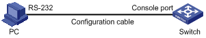
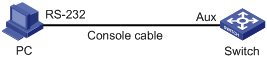
1. As shown in Figure 1, use the console cable shipped with the router to connect the serial port of the PC or terminal to the console port of your router.
Figure 1 Setting up a configuration environment
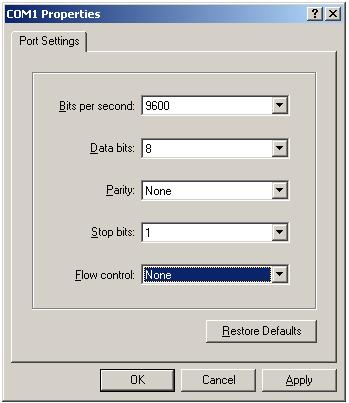
1. Launch a terminal emulation program, such as HyperTerminal in Windows XP or Windows 2000. Here, HyperTerminal of Windows XP is used as an example. Select a serial port to be connected to the router, and set terminal parameters in this way: set Bits per second to 9600, Data bits to 8, Parity to None, Stop bits to 1, and Flow control to None, as shown in Figure 2 through Figure 4.
|
|
NOTE: On Windows 2003 Server operating system, add the HyperTerminal program first, and then log in to and manage the device as described in this document. On Windows 2008 Server, Windows 7, Windows Vista, or some other operating system, obtain a third party terminal control program first, and follow the user guide or online help of that program to log in to the device. |
Figure 2 Connection description
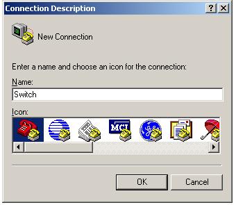
Figure 3 Specifying the serial port used to establish the connection
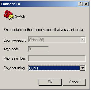
Figure 4 Setting the properties of the serial port
2. Power on the router. You are prompted to press Enter if the router successfully completes the power-on self test (POST). The following prompt appears when you press Enter:
<Sysname>
#May 24 09:27:29:947 2010 R5 SHELL/4/LOGIN:
Trap 1.3.6.1.4.1.25506.2.2.1.1.3.0.1<hh3cLogIn>: login from Console
%May 24 09:27:29:947 2010 R5 SHELL/5/SHELL_LOGIN: Console logged in from con0.
<Sysname>
3. Execute commands to configure the router or check the running status of the router. To get help, enter ?.
After the steps above, you can enter the CLI to configure and manage your router. By default, users that log in from the console port are not authenticated. For security, you are recommended to change the authentication mode of the console port. The following describes how to configure password authentication.
<Sysname> system-view
[Sysname]user-interface console 0
[Sysname-ui-console0]authentication-mode password
[Sysname-ui-console0]set authentication password cipher 123
After the configuration above, when users log in from the console port, they must enter authentication password 123 to pass authentication and then log in to the router.
|
|
NOTE: · You can set the authentication mode of console login users as to none or scheme (username and password authentication). For more information about authentication modes, see “Configuring the authentication mode.” · When users log in from the console port, you can also set other login parameters besides the authentication mode. For more information, see “Configuring asynchronous serial interface attributes“ and “Configuring terminal attributes.” |
Logging in through the AUX port
Configuration prerequisites
Modifying the default settings of the AUX port
Before logging in to your router through the AUX port, modify the default settings of the AUX port on the console port. Otherwise, you cannot log in to your router.
To modify the default settings of the AUX port, follow these steps:
1. Log in to the router through the console port. (For more information, see “Configuration procedure.”)
2. Set the authentication mode for AUX port login.
3. Set the command level to 3.
<Sysname> system-view
[Sysname] user-interface aux 0
[Sysname-ui-aux0] user privilege level 3
|
|
NOTE: When users log in to the router through the AUX port, they can only access commands with the command level 0 by default. For more information about command levels, see “Configuring user privilege level under a user interface.” |
Configuring terminal parameters
To log in to the router through its AUX port, the related configuration of the user terminal must be in accordance with that of the AUX port.
Table 3 lists the default settings of an AUX port.
Table 3 Default settings of an AUX port
|
Setting |
Default |
|
Bits per second |
9,600 bps |
|
Flow control |
None |
|
Parity |
None |
|
Stop bits |
1 |
|
Data bits |
8 |
Configuration procedure
1. As shown in Figure 5, use a console cable to connect the serial port of your PC (or terminal) to the AUX port of your router.
Figure 5 Setting up a configuration environment
2. Launch a terminal emulation program, such as HyperTerminal in Windows XP or Windows 2000. Select a serial port to be connected to the router, and set terminal parameters in this way: set Bits per second to 9600, Data bits to 8, Parity to None, Stop bits to 1, and Flow control to None, as shown in Figure 6 through Figure 8.
|
|
NOTE: On Windows 2003 Server operating system, you need to add the HyperTerminal program first, and then log in to and manage the device as described in this document. On Windows 2008 Server, Windows 7, Windows Vista, or some other operating system, you need to obtain a third party terminal control program first, and follow the user guide or online help of that program to log in to the device. |
Figure 6 Connection description
Figure 7 Specifying the serial port used to establish the connection
Figure 8 Setting the properties of the serial port
3. Power on the router. You are prompted to press Enter if the router successfully completes POST. After you press Enter, a prompt, such as <sysname> (assuming that the router name is sysname), is displayed.
<sysname>
4. Execute commands to configure the router or check the running status of the router. To get help, enter ?.
After the steps above, you can enter the CLI to configure and manage the router.
Logging in through Telnet
Introduction
You can telnet to the router to remotely manage and maintain your it.
To log in to your router through Telnet, perform necessary configurations on both your router and the Telnet client.
Table 4 Telnet login requirements
|
Router |
Requirement |
|
Router |
· Configure the IP address of the network management or Ethernet interface of the router, make sure that the router and the Telnet client can reach each other. · Enable the Telnet server by executing the telnet server enable command in system view. |
|
Configure the authentication mode for Telnet login. (For more information, see “Configuring the authentication mode.” |
|
|
Telnet client |
Run the Telnet program. |
|
Obtain the IP address of the network management or Ethernet interface of the router to log in. |
Setting up a configuration environment
To log in to your router through Telnet, use either of the following methods:
· Use your PC as the Telnet client to telnet to your router and configure it
· Telnet from one router to another, with the local router as the Telnet client, and the remote router as the Telnet server.
Telnetting to your router
1. Configure the IP address of the network management port of the router on the console port.
|
|
IMPORTANT: You can also telnet to your router through a service port. |
a. Set up a configuration environment through the console port. As shown in Figure 9, use a console cable to connect the serial port of the PC to the console port of your router.
Figure 9 Setting up a configuration environment

a. Launch a terminal emulation program, such as HyperTerminal in Windows XP or Windows 2000. Set the terminal parameters in this way: set Bits per second to 9600, Data bits to 8, Parity to None, Stop bits to 1, and Flow control to None.
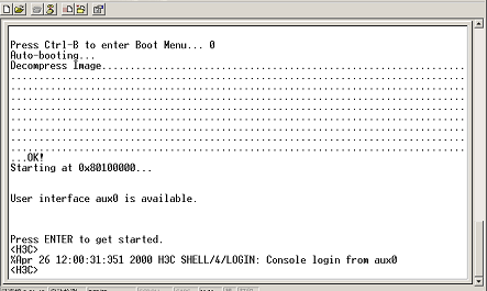
b. Power on the router. You are prompted to press Enter if the router successfully completes POST. A prompt appears after you press Enter, as shown in Figure 10.
a. To configure the network management port of the router as 202.38.160.92/24, execute the following commands on the hyper terminal:
<Sysname> system-view
[Sysname] interface M-Ethernet 0/0/0
[Sysname-M-Ethernet0/0/0] ip address 202.38.160.92 255.255.255.0
|
|
IMPORTANT: If you Telnet to your router through its service port, configure the IP address of VLAN-interface 1 as 202.38.160.92/24 because the service port belongs to VLAN 1 by default. |
2. Before telnetting to your router, perform necessary configurations on your router according to different authentication modes. For more information, see “Configuring the authentication mode.”
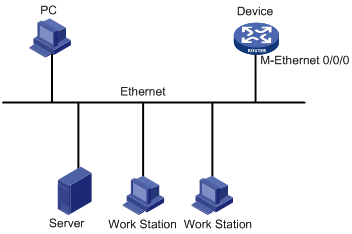
3. Set up a configuration environment as shown in Figure 11: Connect the Ethernet port of the PC to the network management port of your router. Make sure that the PC and router can reach each other.
Figure 11 Setting up a configuration environment
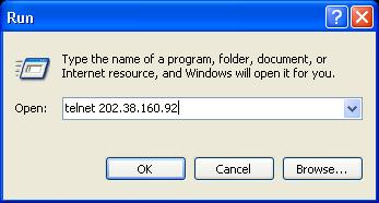
4. Run the Telnet program on the PC, and enter the IP address of the management port of the router, as shown in Figure 12.
Figure 12 Running the Telnet program
5. If the authentication mode is password, the terminal displays “Login authentication”, and prompts you to enter the configured login password. If your password is correct, a command line prompt (for example, <Sysname>) is displayed. If “All user interfaces are used, please try later!” appears, try again later.
6. Execute commands to configure the router, or check the running status of the router. To get help, enter ?.
|
|
NOTE: · When configuring your router through Telnet, do not delete or change the IP address of the network management port or VLAN interface corresponding to the Telnet connection. Otherwise, the Telnet connection may be terminated. · Users that Telnet to the router can only execute command with level 0 by default. For more information about command levels, see “Configuring user privilege level under a user interface.” |
Telnetting from a router to another router
You can configure a router by telnetting from another router to it. The local router operates as the Telnet client, and the remote router as the Telnet server. If the two routers are in the same LAN, you must configure their IP addresses to be in the same segment, or make sure that the two routers can reach each other.
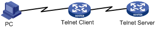
Set up a configuration environment as shown in Figure 13. After you log in to the Telnet client, you can execute the telnet command to log in to the Telnet server to configure and manage the server.
Figure 13 Telnetting from a router to another router
1. Configure the router that operates as the Telnet server.
a. Enable Telnet on the Telnet server.
To enable Telnet on the router:
|
Step |
Command |
Remarks |
|
1. Enter system view. |
system-view |
N/A |
|
2. Enable Telnet. |
telnet server enable |
Disabled by default. |
b. Perform corresponding configurations on the Telnet server according to different authentication modes. For more information, see “Configuring the authentication mode.”
2. Log in to the router that operates as the Telnet client.
3. Execute the telnet command on the Telnet client to log in to the router that operates as the Telnet server.
<Sysname> telnet xxxx
xxxx is the host name, IP address, or VPN instance name of the router that operates as the Telnet server. If it is a host name, it must be a host name configured with the ip host command.
To use a router as the Telnet client to log in to another router:
|
Task |
Command |
Remarks |
|
Use the router to log in to another router in an IPv4 network. |
telnet remote-host [ service-port ] [ [ vpn-instance vpn-instance-name ] | [ source { interface interface-type interface-number | ip ip-address } ] ] |
Available in user view |
|
Use the router to log in to another router in an IPv6 network. |
telnet ipv6 remote-host [ -i interface-type interface-number ] [ port-number ] [ vpn-instance vpn-instance-name ] |
4. After login, a prompt appears (for example, <Sysname>). If the “All user interfaces are used, please try later!” message is displayed, try again later.
5. Execute corresponding commands to configure the router, or check the running status of the router. To get help, enter ?.
Logging in through SSH
Introduction
Secure Shell (SSH) offers an approach to log in to a remote device securely. By providing encryption and strong authentication, SSH protects devices against malicious attacks such as IP spoofing and plain text password interception. The router supports SSH, and you can log in to the switch through SSH to remotely manage and maintain the router, as shown in Figure 14.
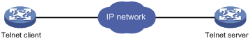
The following table shows the configuration requirements of SSH login.
|
Object |
Requirements |
|
SSH server |
Configure the IP address of the SSH server, and make sure the SSH server and client can reach each other. |
|
Configure the authentication mode and other settings. |
|
|
SSH client |
Run the SSH client program. |
|
Obtain the IP address of the SSH server. |
The router can operate as either an SSH server or client.
As an SSH server:
· You can perform configurations on the SSH server to control SSH client login.
· By default, the router is disabled with the SSH server function. Before you can log in to the router through SSH, you need to log in to the router through the console port and configure the authentication mode, user level, and common settings.
As an SSH client:
· You can log in to an SSH sever from the client to perform operations on the server.
· By default, the switch is enabled with the SSH client function.
Logging in to the router from an SSH client
Configuration prerequisites
Log in to the router through the console port. For more information, see “Logging in through the console port.”
Configuration procedure
To configure the router that serves as an SSH server:
|
Step |
Command |
Remarks |
|
1. Enters system view. |
system-view |
N/A |
|
2. Create local key pair(s). |
public-key local create { dsa | rsa } |
By default, no local key pair(s) are created. |
|
3. Enable the SSH server. |
ssh server enable |
By default, SSH server is disabled. |
|
4. Exit to system view. |
quit |
N/A |
|
5. Enter one or more VTY user interface views. |
user-interface vty first-number [ last-number ] |
N/A |
|
6. Specify the scheme authentication mode. |
authentication-mode scheme |
By default, authentication mode for VTY user interfaces is password. |
|
7. Enable the current user interface to support either Telnet, SSH, or both of them. |
protocol inbound { all | ssh | telnet } |
Optional. By default, both protocols are supported. |
|
8. Return to system view. |
quit |
N/A |
|
9. Create a local user and enter local user view. |
local-user user-name |
By default, no local user exists. |
|
10. Set the local password. |
password { cipher | simple } password |
By default, no local password is set. |
|
11. Specifies the command level of the local user. |
authorization-attribute level level |
Optional. By default, the command level is 0. |
|
12. Specify the service type for the local user. |
service-type ssh |
By default, no service type is specified. |
|
13. Return to system view. |
quit |
N/A |
|
14. Create an SSH user, and specify the authentication mode for the SSH user. |
ssh user username service-type stelnet authentication-type { password | { any | password-publickey | publickey } assign publickey keyname } |
By default, no SSH user exists, and no authentication mode is specified. |
|
15. Configure common settings for VTY user interfaces. |
N/A |
Optional. |
|
|
NOTE: · Login procedures from an SSH client to the router (SSH server) depend on the model of the device that serves as the SSH client. For more information, see the user guide of the device that serves as the SSH client. · For more information about SSH, see Security Configuration Guide. |
Configuring the SSH client to log in to the SSH server
Configuration prerequisites
Log in to the router through the console port. For more information, see “Logging in through the console port.”
Figure 15 Logging in to another device from the current device
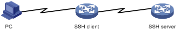
|
|
NOTE: If the Telnet client and the Telnet server are not in the same subnet, make sure that the two devices can reach each other. |
Configuration procedure
To configure the SSH client to log in to the SSH server:
|
Task |
Command |
Remarks |
|
Log in to an IPv4 SSH server. |
ssh2 server [ port-number ] [ vpn-instance vpn-instance-name ] [ identity-key { dsa | rsa } | prefer-ctos-cipher { 3des | aes128 | des } | prefer-ctos-hmac { md5 | md5-96 | sha1 | sha1-96 } | prefer-kex { dh-group-exchange | dh-group1 | dh-group14 } | prefer-stoc-cipher { 3des | aes128 | des } | prefer-stoc-hmac { md5 | md5-96 | sha1 | sha1-96 } ] * |
server is the IPv4 address or host name of the server. Available in user view. |
|
Log in to an IPv6 SSH server. |
ssh2 ipv6 server [ port-number ] [ vpn-instance vpn-instance-name ] [ identity-key { dsa | rsa } | prefer-ctos-cipher { 3des | aes128 | des } | prefer-ctos-hmac { md5 | md5-96 | sha1 | sha1-96 } | prefer-kex { dh-group-exchange | dh-group1 | dh-group14 } | prefer-stoc-cipher { 3des | aes128 | des } | prefer-stoc-hmac { md5 | md5-96 | sha1 | sha1-96 } ] * |
server is the IPv6 address or host name of the server. Available in user view. |
|
|
NOTE: You can configure other settings for the router (SSH client) to work with the SSH server. For more information, see Security Configuration Guide. |
Logging in through the AUX port by using modems
Introduction
An administrator can use two modems and the Public Switched Telephone Network (PSTN) to remotely maintain a remote router through its AUX port. This mode is applicable to remotely configure a router, query logs and alarms, and locate faults through a PSTN when a network connection is broken.
To ensure a successful remote login to a router through the AUX port, perform necessary configurations at both the router side and administrator side.
Table 5 Requirements on remote login through AUX port by using modem
|
Router |
Requirement |
|
Administrator side |
The PC is correctly connected to the modem. |
|
The modem is connected to a telephone cable that works normally. |
|
|
The telephone number of the modem connected to the AUX port of the remote router is obtained. |
|
|
Router side |
The AUX port is correctly connected to the modem. |
|
Configurations have been made on the modem. |
|
|
The modem is connected to a telephone cable that works properly. |
|
|
Authentication modes are configured on the remote router. For more information, see “Configuring the authentication mode.” |
Configurations on the administrator side
Perform these configurations on the administrator side:
1. Correctly connect the PC and the modem.
2. Connect the modem to a telephone cable in good working condition.
3. Obtain the telephone number on the modem connected to the AUX port of the remote router.
Configurations on the router
Configuration on the modem that is directly connected to the router
Perform the following configurations on the modem that is directly connected to the router (no configuration is needed on the modem connected to the terminal):
AT&F ----------------------- Restore the factory defaults
ATS0=1 ----------------------- Configure auto-answer on first ring
AT&D ----------------------- Ignore data Terminal Ready signals
AT&K0 ----------------------- Disable local flow control
AT&R1 ----------------------- Ignore Data Flow Control signals
AT&S0 ----------------------- Force DSR to remain on
ATEQ1&W ----------------------- Disable the modem from response to commands and save the configuration
To verify your configuration, enter AT&V to display the configuration results.
|
|
NOTE: The configuration commands and the output for different modems may be different. For more information, see the user guide of your modem. |
Configuration on the router
When configuring the router, note the following guidelines:
· The transmission speed on the AUX port is lower than that of the modem. Otherwise, packets may be lost.
· Other attributes, such as parity check, stop bits, and data bits, of the AUX port are set to the default values.
Setting up a configuration environment
1. Before logging in to your router by using modems, perform corresponding configurations on your router. For more information, see “Modifying the default settings of the AUX port.”
2. Perform the following configurations on the modem that is directly connected to your router:
AT&F ----------------------- Factory defaults
ATS0=1 ----------------------- Auto-answer on first ring
AT&D ----------------------- Data Terminal Ready
AT&K0 ----------------------- Local flow control
AT&R1 ----------------------- Disables Receive Data Flow Control
AT&S0 ----------------------- DSR action select
ATEQ1&W ----------------------- Disables the modem's response to the command and saves the configuration
To verify your configuration, execute the AT&V command to display the configuration results.
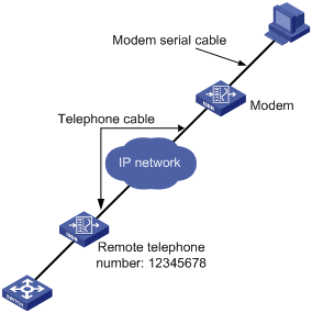
3. Set up a configuration environment as shown in Figure 16: connect the serial port of the PC and the AUX port of the router to a modem respectively.
Figure 16 Setting up a configuration environment
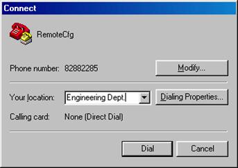
4. On the PC, dial a number of the modem that is connected to the router to establish a connection with the router, as shown in Figure 17 through Figure 19.
Figure 17 Connection Description
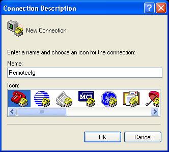
Figure 18 Entering the phone number
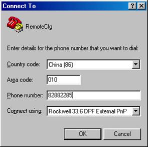
Figure 19 Dialing the number on the remote PC
5. If the authentication mode is password, a prompt (for example, sysname) appears when you enter the configured password on the remote terminal. Then you can configure or manage the router. To get help, enter ?.
User interface overview
Brief introduction
A user interface, also called line, enables you to manage and monitor sessions between the terminal and the router when you log in to the router through the console port, AUX port, an asynchronous serial interface, or through Telnet or SSH.
Asynchronous serial interfaces include the following two types:
· Synchronous/asynchronous serial interface operating in asynchronous mode, the interface index of which begins with Serial.
· Dedicated asynchronous serial interface, the interface index of which begins with Async.
A single user interface corresponds to a single user interface view where you can configure a set of parameters, such as whether to authenticate users at login, whether to redirect the requests to another device, and the user privilege level after login.
When the user logs in through a user interface, the connection follows these parameter settings, implementing centralized management of various sessions.
At present, the system supports the following CLI configuration methods:
· Local configuration via the console port
· Local or remote configuration via the AUX port (Auxiliary port)
· Local or remote configuration through Telnet or SSH
The CLI configuration methods correspond to the following types of user interfaces:
· Console user interface—Manages and monitors users that log in via the console port. The console port is a line router port. The router provides console ports of EIA/TIA-232 DCE type.
· AUX user interface—Manages and monitors users that log in via the AUX port. The AUX port is also a line router port. The router provides AUX ports of EIA/TIA-232 DTE type. The port is usually used for dialup access via a modem.
· VTY (virtual type terminal) user interface—Manages and monitors users logging in via VTY. A VTY port is a logical terminal line used when you access the router through Telnet or SSH. At present, the router supports at most 16 concurrent VTY users.
Users and user interfaces
At a time, only one user can use a user interface. The configuration made in a user interface view applies to any user logged in to that user interface. For example, if user A uses the console port to log in, the configuration in the console port user interface view applies to user A. If user A logs in through VTY 1, the configuration in the VTY 1 user interface view applies to user A.
A router can support multiple console ports, AUX ports, asynchronous serial interfaces, and Ethernet interfaces or a combination of all of these. Hence, a router supports multiple user interfaces. These user interfaces do not associate with specific users. When a user initiates a connection request, the system automatically assigns an idle user interface with the smallest number to the user based on the login method. During login, the configuration in the user interface view takes effect. The user interface varies depending on the login method and login time.
Numbering user interfaces
User interfaces are numbered in two ways: absolute numbering and relative numbering.
Absolute numbering
Absolute numbering identifies a user interface or a group of different types of user interfaces. The specified user interfaces are numbered from 0 with a step of 1 in this sequence: console, AUX, and VTY user interfaces. You can use the display user-interface command without any parameters to view supported user interfaces and their absolute numbers.
Relative numbering
Relative numbering enables you to specify a user interface or a group of user interfaces of a specific type. The number is valid only when used under that type of user interface. It is invalid when used under any other type of user interface.
Relative numbering numbers a user interface in the form of “user interface type + number”. The rules of relative numbering are as follows:
· Console ports are numbered from 0 in the ascending order, with a step of 1.
· AUX ports are numbered from 0 in the ascending order, with a step of 1.
· VTYs are numbered from 0 in the ascending order, with a step of 1.
User interface configuration task list
Complete these tasks to configure a user interface:
|
Task |
Remarks |
|
Optional |
|
|
Optional |
|
|
Optional |
|
|
Optional |
|
|
Optional |
|
|
Optional |
|
|
Optional |
|
|
Optional |
|
|
Optional |
|
|
Defining shortcut keys for starting terminal sessions/aborting tasks |
Optional |
|
Optional |
|
|
Optional |
Configuring asynchronous serial interface attributes
A serial interface contains the following key attributes:
· Transmission rate—Number of bits that the router transmits to the terminal per second. It measures the transmission speed. Typically a higher transmission rate is used between closer distances for communication.
· Data bits—Number of bits representing one character. The setting depends on the contexts to be transmitted, For example, you can set it to 7 if standard ASCII characters are to be sent; set it to 8 if extended ASCII characters are to be sent.
· Parity check—An error checking technique to detect whether errors occurred in the data transmission.
· Stop bits—The last bits transmitted in data transmission to unequivocally indicate the end of a character. The more the bits are, the slower the transmission is.
These attribute settings must be consistent on two user interfaces for communication.
To configure asynchronous attributes of a serial interface:
|
Step |
Command |
Remarks |
|
1. Enter system view. |
system-view |
N/A |
|
2. Enter user interface view. |
user-interface { first-num1 [ last-num1 ] | { aux | console } first-num2 [ last-num2 ] } |
N/A |
|
3. Configure the transmission rate. |
speed speed-value |
Optional. 9600 bps by default. |
|
4. Configure the data bits for each character. |
databits { 5 | 6 | 7 | 8 } |
Optional. 8 by default. The router does not support data bits 5 and 6. |
|
5. Configure a parity check method. |
parity { even | mark | none | odd | space } |
Optional. None by default. |
|
6. Configure the number of stop bits transmitted per byte. |
stopbits { 1 | 1.5 | 2 } |
Optional. 1 by default. |
|
7. Configure the flow control mode. |
flow-control { hardware | software | none } |
Optional. By default, the flow control mode is none. The router does not support the hardware and software keywords. |
Configuring terminal attributes
To configure terminal attributes:
|
Step |
Command |
Remarks |
|
1. Enter system view. |
system-view |
N/A |
|
2. Enter user interface view. |
user-interface { first-num1 [ last-num1 ] | { aux | console | vty } first-num2 [ last-num2 ] } |
N/A |
|
3. Start the terminal service. |
shell |
Optional. The terminal service is enabled on all user interfaces by default. |
|
4. Set the idle-timeout disconnection function for terminal users. |
idle-timeout minutes [ seconds ] |
Optional. 10 minutes by default. |
|
5. Set the number of lines on a screen. |
screen-length screen-length |
Optional. By default, up to 24 lines of data are displayed on a screen. |
|
6. Set the display type of the current user terminal. |
terminal type { ansi | vt100 } |
Optional. ANSI by default. |
|
7. Set the size of the history command buffer of the user interface. |
history-command max-size size-value |
Optional. The history buffer can store 10 commands by default. |
|
8. Return to user view. |
return |
N/A |
|
9. Lock the user interface to prevent unauthorized users from using this interface. |
lock |
Optional. Disabled by default. |
Configuring a command to be automatically executed
The system automatically executes a command when a user logs in by using the user interface where the auto-execute command command is configured. The system tears down the user connection after the command completes. If the auto-execution command command triggers another task or connection, the system does not tear down the user connection until the task completes or the triggered connection breaks down.
A good example is configuring the auto-execute command telnet command to let users automatically telnet to the specified host.
To configure auto-execute command:
|
Step |
Command |
Remarks |
|
1. Enter system view. |
system-view |
N/A |
|
2. Enter user interface view. |
user-interface { first-num1 [ last-num1 ] | { aux | vty } first-num2 [ last-num2 ] } |
N/A |
|
3. Configure the command to be automatically executed. |
auto-execute command command |
By default, no command is set to be automatically executed. |
The auto-execute command command is not supported by the console port, or the AUX port when the router has only one AUX port and no console port.
|
|
CAUTION: The auto-execute command command may disable you from configuring the system through the user interface to which the command is applied. Therefore, before configuring the command and saving the configuration (by using the save command), make sure that you can access the router by other VTY, console, or AUX user interfaces to remove the configuration in case a problem occurs. |
Configuring user privilege level under a user interface
User privilege levels restrict the access rights of different users to the router.
· If the authentication mode is scheme when a user logs in, which means username and password are needed, and SSH public key authentication is adopted, the privilege level of the user is the user interface level, which is configured in user interface view. The default user interface level is 0.
· If the authentication mode is none or password when a user logs in, which means no username is needed, the privilege level of the user is the user interface level.
To configure the user privilege level under a user interface:
|
Step |
Command |
Remarks |
|
1. Enter system view. |
system-view |
N/A |
|
2. Enter user interface view. |
user-interface { first-num1 [ last-num1 ] | { aux | console | vty } first-num2 [ last-num2 ] } |
N/A |
|
3. Configure user’s privilege level under the current user interface. |
user privilege level level |
Optional. By default, users logging in through console port have a privilege level of 3; users logging in through other user interfaces have a privilege level of 0. |
Configuring access control on VTY user interfaces
You can configure access control on the VTY user interface by referencing an ACL. For more information about ACL, see ACL and QoS Configuration Guide.
To control access to VTY user interfaces:
Configuring supported protocols on VTY user interfaces
To configure supported protocols on the active VTY user interface:
|
Step |
Command |
Remarks |
|
1. Enter system view. |
system-view |
N/A |
|
2. Enter VTY user interface view. |
user-interface { first-num1 [ last-num1 ] | vty first-num2 [ last-num2 ] } |
N/A |
|
3. Configure the supported protocols on the current user interface. |
protocol inbound { all | pad | ssh | telnet } |
Optional. Support for the pad keyword depends on the router model. By default, both Telnet and SSH are supported. |
|
|
CAUTION: · If SSH is configured, you must set the authentication mode to scheme by using the authentication-mode scheme command to guarantee a successful login. The protocol inbound ssh command fails if the authentication mode is password or none. · The protocols configured through the protocol inbound command take effect next time you log in through that user interface. |
Configuring the authentication mode
Authentication mode under a user interface determines whether to authenticate users that are logging in through the user interface. The method enhances the security of the router. The router supports authentication modes of none, password, and scheme.
· none—Requires no username and password when users log in through the specified user interface. This mode is insecure.
· password—Requires password authentication on users that are logging in through the user interface. Always set the password for this mode before terminating your current connection. Next time when a user attempts to use the user interface to log in, an empty or wrong password fails the login. If no authentication password is set for this mode on the AUX or VTY user interface, no user can log in, and the system displays "Login password has not been set!" If no password is set on the console user interface, login without a password is allowed.
· scheme—Requires username and password authentication on users that are logging in through the user interface. Always set the username and password for this mode before terminating your current connection. Next time when a user attempts to use the user interface to log in, an empty or wrong username or password fails the login.
User authentication falls into local authentication and remote authentication. If local authentication is adopted, configure a local user and the related parameters as shown in the table for configuring authentication mode as scheme. If remote authentication is adopted, configure username and password on the remote authentication server. For more information about the user authentication modes and parameters, see Security Configuration Guide. By default, the router performs local authentication on users. If you log in to the router through SSH, the rules apply to password authentication only. For more information about SSH, see Security Configuration Guide.
To configure the authentication mode as none:
|
Step |
Command |
Remarks |
|
1. Enter system view. |
system-view |
N/A |
|
2. Enter user interface view. |
user-interface { first-num1 [ last-num1 ] | { aux | console | vty } first-num2 [ last-num2 ] } |
N/A |
|
3. Configure not to authenticate users that are logging in through the current user interface. |
authentication-mode none |
By default, password is for VTY and AUX logins, and none is for console logins. |
To configure the authentication mode as password:
|
Step |
Command |
Remarks |
|
1. Enter system view. |
system-view |
N/A |
|
2. Enter user interface view. |
user-interface { first-num1 [ last-num1 ] | { aux | console | vty } first-num2 [ last-num2 ] } |
N/A |
|
3. Configure to perform password authentication on users that are logging in through the current user interface. |
authentication-mode password |
By default, password is for VTY and AUX logins, and none is for console logins. |
|
4. Set the local authentication password. |
set authentication password { cipher | simple } password |
No local authentication password is set by default. |
To configure the authentication mode as scheme (local authentication):
|
Step |
Command |
Remarks |
|
1. Enter system view. |
system-view |
N/A |
|
2. Enter user interface view. |
user-interface { first-num1 [ last-num1 ] | { aux | console | vty } first-num2 [ last-num2 ] } |
N/A |
|
3. Configure to perform AAA authentication on users that are logging in through the current user interface. |
authentication-mode scheme |
By default, password is for VTY and AUX logins, and none is for console logins. |
|
4. Set the user privilege level. |
See “Configuring user privilege level under a user interface.” |
Optional. By default, users logging in through the console port have a privilege level of 3; users logging in through other user interfaces have a privilege level of 0. |
|
5. Return to system view. |
quit |
N/A |
|
6. Set the authentication username and enter local user view. |
local-user user-name |
No local user is set on the router by default. |
|
7. Set the authentication password. |
password { cipher | simple } password |
N/A |
|
8. Set the service type that can be used by users. |
service-type { ssh | telnet | terminal } * |
Users logging in via VTY user interface use telnet or ssh service. Users logging in via console or AUX port use terminal service. |
|
9. Configure user attributes. |
authorization-attribute { acl acl-number | callback-number callback-number | idle-cut minute | level level | user-profile profile-name | vlan vlan-id | work-directory directory-name } * |
Optional. By default, FTP/SFTP users can access the router's root directory with the user level 0. |
|
|
NOTE: For more information about the local-user, password, service-type, and authorization-attribute commands, see Security Command Reference. |
Configuring command authorization
By default, command level for a login user depends on the user level. The user is authorized to execute commands whose default level is not higher than the user level.
If you configure command authorization, the command level for a login user is determined by both the user level and AAA authorization. If a user executes a command of the corresponding user level, the authorization server checks whether the command is authorized. If yes, the command can be executed.
To configure command authorization, you must:
1. Configure the authentication mode as scheme, which requires both the username and password for login authentication.
2. Enable command authorization.
3. Configure an HWTACACS scheme. Specify the IP addresses of the HWTACACS authorization servers and other related parameters.
4. Configure the ISP domain to use the HWTACACS scheme for command line users. For more information about HWTACACS configuration, see Security Configuration Guide.
To enable command authorization:
|
Step |
Command |
Remarks |
|
1. Enter system view. |
system-view |
N/A |
|
2. Enter user interface view. |
user-interface { first-num1 [ last-num1 ] | { aux | console | vty } first-num2 [ last-num2 ] } |
N/A |
|
3. Enable command authorization. |
command authorization |
By default, command authorization is disabled, and users can execute commands without authorization. |
Configuring command accounting
Command accounting allows the HWTACACS server to record all executed commands that are supported by the router, regardless of the command execution result. This helps control and monitor user operations on the router.
If command accounting is enabled and command authorization is not enabled, every executed command is recorded on the HWTACACS server. If both command accounting and command authorization are enabled, only the authorized and executed commands are recorded on the HWTACACS server.
To configure command accounting, you must:
1. Enable command accounting.
2. Configure an HWTACACS scheme. Specify the IP addresses of the HWTACACS accounting servers and other related parameters.
3. Configure the ISP domain to use the HWTACACS scheme for command line users. For more information about HWTACACS configurations, see Security Configuration Guide.
|
Step |
Command |
Remarks |
|
1. Enter system view. |
system-view |
N/A |
|
2. Enter user interface view. |
user-interface { first-num1 [ last-num1 ] | { aux | console | vty } first-num2 [ last-num2 ] } |
N/A |
|
3. Enable command accounting. |
command accounting |
By default, command accounting is disabled, and the accounting server does not record the commands the users execute. |
Defining shortcut keys for starting terminal sessions/aborting tasks
To define shortcut keys for starting terminal sessions/aborting tasks:
|
Step |
Command |
Remarks |
|
1. Enter system view. |
system-view |
N/A |
|
2. Enter user interface view. |
user-interface { first-num1 [ last-num1 ] | { aux | console | vty } first-num2 [ last-num2 ] } |
N/A |
|
3. Define a shortcut key for starting a terminal session. |
activation-key character |
Optional. Pressing Enter starts the terminal session by default. |
|
4. Define a shortcut key for aborting a task. |
escape-key { default | character } |
Optional. By default, the escape key sequence Ctrl+C is to abort a task. |
|
|
NOTE: The activation-key command is not supported on the VTY user interface. |
Sending messages to the specified user interfaces
To send messages to the specified user interfaces:
|
Task |
Command |
Remarks |
|
Send messages to the specified user interfaces. |
send { all | num1 | { aux | console | vty } num2 } |
Available in user view |
Releasing the connection established on user interfaces
Multiple users can log in to the system to simultaneously configure the router. In some circumstances, when the administrator wants to make configurations without interruption from the users that have logged in through other user interfaces, the administrator can execute the following commands to release the connection established on the specified user interfaces.
To release the connection established on the user interfaces:
|
Task |
Command |
Remarks |
|
Release the connection established on the specified user interfaces. |
free user-interface { num1 | { aux | console | vty } num2 } |
Available in user view |
|
|
NOTE: You cannot use this command to release the connection that you are using. |
Displaying and maintaining user interfaces
|
Task |
Command |
Remarks |
|
Display the Telnet configuration when the router serves as a Telnet client. |
display telnet client configuration [ | { begin | exclude | include } regular-expression ] |
Available in any view |
|
Display information about all the user interfaces supported on the router. |
display users [ all ] [ | { begin | exclude | include } regular-expression ] |
Available in any view |
|
Display information about the specified or all user interfaces. |
display user-interface [ num1 | { aux | console | vty } num2 ] [ summary ] [ | { begin | exclude | include } regular-expression ] |
Available in any view |
User interface configuration examples
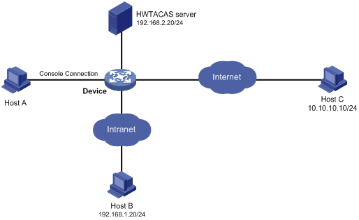
User authentication configuration example
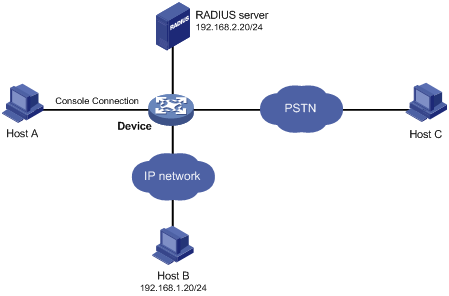
Network requirements
As shown in Figure 20, three administrators need to access Device for device management: one through a console port, one through an IP network, and one through a public switched telephone network (PSTN).
Configure Device to:
· Perform no authentication for users who log in through the console port.
· Perform password authentication for users who log in through the IP network.
· Use the RADIUS server to authenticate users who log in through the PSTN, and use local authentication as the backup.
· Assign different command levels to different types of users.
Configuration procedure
# Assign IP addresses to the interfaces on Device so that Device and Host B can reach each other and Device and the RADIUS server can reach each other. (Details not shown)
# Enable the Telnet service on Device.
<Sysname> system-view
[Sysname] telnet server enable
# Configure Device to perform no authentication for users logging in through the console port and to allow the users to use commands of privilege level 3 (all commands).
[Sysname] user-interface console 0
[Sysname-ui-console0] authentication-mode none
[Sysname-ui-console0] user privilege level 3
[Sysname-ui-console0] quit
# Configure Device to perform password authentication for users logging in to VTY user interfaces 0 through 4. Set the password to 123, and set the privilege level of the users to 2.
[Sysname] user-interface vty 0 4
[Sysname-ui-vty0-4] authentication-mode password
[Sysname-ui-vty0-4] set authentication password cipher 123
[Sysname-ui-vty0-4] user privilege level 2
[Sysname-ui-vty0-4] quit
# Configure Device to use AAA to authenticate users logging in to user interface VTY 5.
[Sysname] user-interface vty 5
[Sysname-ui-vty5] authentication-mode scheme
[Sysname-ui-vty5] quit
# Create a RADIUS scheme and configure the IP address and UDP port for the primary authentication server for the scheme. Make sure that the port number is consistent with that on the RADIUS server. Set the shared key for authentication packets to expert for the scheme and the RADIUS server type of the scheme to extended. Configure Device to remove the domain name in the username sent to the RADIUS server.
[Sysname] radius scheme rad
[Sysname-radius-rad] primary authentication 192.168.2.20 1812
[Sysname-radius-rad] key authentication expert
[Sysname-radius-rad] server-type extended
[Sysname-radius-rad] user-name-format without-domain
[Sysname-radius-rad] quit
# Configure the default ISP domain system to use RADIUS scheme rad for login users and use local authentication as the backup.
[Sysname] domain system
[Sysname-isp-system] authentication login radius-scheme rad local
[Sysname-isp-system] authorization login radius-scheme rad local
[Sysname-isp-system] quit
# Add a local user named monitor, set the user password to 123, and specify to display the password in cipher text. Authorize user monitor to use the Telnet service and specify the level of the user as 1, the monitor level.
[Sysname] local-user monitor
[Sysname-luser-admin] password cipher 123
[Sysname-luser-admin] service-type telnet
[Sysname-luser-admin] authorization-attribute level 1
Command authorization configuration example
Network requirements
As shown in Figure 21, configure Device to use the HWTACACS server to authenticate and perform command line authorization for users accessing the VTY interfaces 0 through 4, and use local authentication and authorization as the backup.
Configuration procedure
# Assign an IP address to Device so that Device and Host A, and Device and the HWTACACS server can reach each other. (Details not shown)
# Enable the Telnet service on Device.
<Sysname> system-view
[Sysname] telnet server enable
# Configure Device to use AAA to control user access to VTY interfaces 0 through 4.
[Sysname] user-interface vty 0 4
[Sysname-ui-vty0-4] authentication-mode scheme
# Enable command authorization to restrict the command level for login users.
[Sysname-ui-vty0-4] command authorization
[Sysname-ui-vty0-4] quit
# Create an HWTACACS scheme named tac and configure the IP address and TCP port for the primary authorization server for the scheme. Make sure that the port number is consistent with that on the HWTACACS server. Set the shared key for authentication packets to expert for the scheme and the HWTACACS server type of the scheme to standard. Specify Device to remove the domain name in the username that is sent to the HWTACACS server.
[Sysname] hwtacacs scheme tac
[Sysname-hwtacacs-tac] primary authentication 192.168.2.20 49
[Sysname-hwtacacs-tac] primary authorization 192.168.2.20 49
[Sysname-hwtacacs-tac] key authentication expert
[Sysname-hwtacacs-tac] key authorization expert
[Sysname-hwtacacs-tac] server-type standard
[Sysname-hwtacacs-tac] user-name-format without-domain
[Sysname-hwtacacs-tac] quit
# Configure the default ISP domain system to use HWTACACS scheme tac for login users and use local authorization as the backup.
[Sysname] domain system
[Sysname-isp-system] authentication login hwtacacs-scheme tac local
[Sysname-isp-system] authorization command hwtacacs-scheme tac local
[Sysname-isp-system] quit
# Add a local user named monitor, set the user password to 123, and specify to display the password in cipher text. Authorize user monitor to use the Telnet service and specify the level of the user as 1, that is, the monitor level.
[Sysname] local-user monitor
[Sysname-luser-admin] password cipher 123
[Sysname-luser-admin] service-type telnet
[Sysname-luser-admin] authorization-attribute level 1
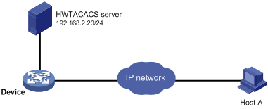
Command accounting configuration example
Network requirements
As shown in Figure 22, configure the device to send commands that login users execute to the HWTACACS server to control and monitor user operations.
Configuration procedure
# Enable the Telnet service on Device.
<Sysname> system-view
[Sysname] telnet server enable
# Enable command accounting for users logging in through the console port.
[Sysname] user-interface console 0
[Sysname-ui-console0] command accounting
[Sysname-ui-console0] quit
# Enable command accounting for users logging in through Telnet or SSH.
[Sysname] user-interface vty 0 4
[Sysname-ui-vty0-4] command accounting
[Sysname-ui-vty0-4] quit
# Create an HWTACACS scheme named tac and configure the IP address and TCP port for the primary authorization server for the scheme. Make sure that the port number is consistent with that on the HWTACACS server. Set the shared key for authentication packets to expert for the scheme. Specify Device to remove the domain name in the username that is sent to the HWTACACS server.
[Sysname] hwtacacs scheme tac
[Sysname-hwtacacs-tac] primary accounting 192.168.2.20 49
[Sysname-hwtacacs-tac] key accounting expert
[Sysname-hwtacacs-tac] user-name-format without-domain
[Sysname-hwtacacs-tac] quit
# Create ISP domain system, and configure the ISP domain to use HWTACACS scheme tac for accounting of command line users
[Sysname] domain system
[Sysname-isp-system] accounting command hwtacacs-scheme tac
[Sysname-isp-system] quit