- Table of Contents
-
- 06-Layer 3 - IP Services Configuration Guide
- 00-Preface
- 01-ARP Configuration
- 02-IP Addressing Configuration
- 03-DHCP Configuration
- 04-DNS Configuration
- 05-NAT Configuration
- 06-IP Forwarding Basics Configuration
- 07-Adjacency Table Configuration
- 08-IP Performance Optimization Configuration
- 09-UDP Helper Configuration
- 10-IPv6 Basics Configuration
- 11-DHCPv6 Configuration
- 12-IPv6 DNS Configuration
- 13-Tunneling Configuration
- 14-GRE Configuration
- Related Documents
-
| Title | Size | Download |
|---|---|---|
| 14-GRE Configuration | 265.83 KB |
GRE encapsulation and de-encapsulation processes
Configuring a GRE over IPv4 tunnel
Displaying and maintaining GRE
GRE over IPv4 tunnel configuration examples
GRE over IPv4 tunnel configuration example 1
GRE over IPv4 tunnel configuration example 2
GRE overview
Generic Routing Encapsulation (GRE) is a protocol designed for encapsulating and carrying the packets of one network layer protocol (for example, IP or IPX) over another network layer protocol (for example, IP). The path that transfers the encapsulated packets is referred to as a GRE tunnel.
A GER tunnel is a virtual point-to-point (P2P) connection. Packets are encapsulated at one end of the tunnel and de-encapsulated at the other end.
GRE encapsulation format
Figure 1 GRE encapsulation format
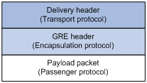
As Figure 1 shows, a GRE-tunneled packet comprises the following parts:
· Payload packet—The packet to be encapsulated and transmitted. The protocol type of the payload is called the passenger protocol.
· GRE header—After the system receives a payload packet, it adds a GRE header to the payload packet, so that the payload packet can be transferred as a GRE packet. The GRE protocol, which encapsulates the payload packet, is called the encapsulation protocol.
· Delivery header—The protocol used to transfer the GRE packet over the network is called the delivery protocol or transport protocol. The system adds a transport protocol header to the GRE packet to deliver it to the tunnel end.
For example, to transfer an IPv6 packet over an IPv4 network through a GRE tunnel, the system encapsulates the IPv6 packet in the format shown in Figure 2. The passenger protocol is IPv6, the encapsulation protocol is GRE, and the transport protocol is IPv4.
Figure 2 Format of a GRE-encapsulated packet
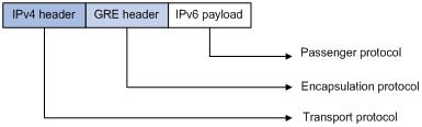
The switch supports GRE over IPv4 tunnels. In GRE over IPv4 tunnel mode, the transport protocol is IPv4, and the passenger protocol is any network layer protocol.
GRE encapsulation and de-encapsulation processes
Figure 3 X protocol networks interconnected through a GRE tunnel
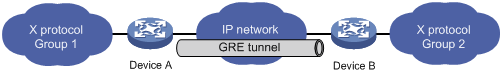
The following takes the network shown in Figure 3 as an example to describe how an X protocol packet traverses the IP network through a GRE tunnel.
Encapsulation process
1. After receiving an X protocol packet through the interface connected to Group 1, Device A submits it to the X protocol for processing.
2. The X protocol checks the destination address field in the packet header to determine how to route the packet.
3. If the packet must be tunneled to reach its destination, Device A sends it to the tunnel interface.
4. Upon receipt of the packet, the tunnel interface encapsulates it in a GRE packet. Then, the system encapsulates the packet in an IP packet and forwards the IP packet based on its destination address and the routing table.
De-encapsulation process
De-encapsulation is the reverse of the encapsulation process:
1. Upon receiving an IP packet from the tunnel interface, Device B checks the destination address.
2. If the destination is itself and the protocol number in the IP header is 47 (the protocol number for GRE), Device B strips off the IP header of the packet and submits the resulting packet to the GRE protocol.
3. The GRE protocol checks the key, checksum and sequence number in the packet, and then strips off the GRE header and submits the payload to the X protocol for forwarding.
|
|
NOTE: Encapsulation and de-encapsulation processes on both ends of the GRE tunnel and the resulting increase in data volumes will degrade the forwarding efficiency of a GRE-enabled device to some extent. |
GRE applications
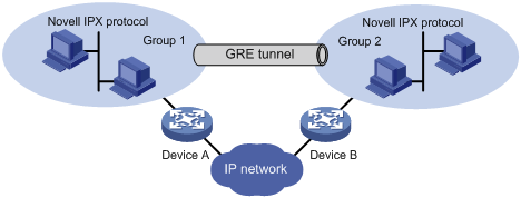
Multi-protocol communications through a single-protocol backbone
Figure 4 Multi-protocol communications through a single-protocol backbone
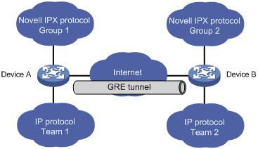
In the example shown in Figure 4, Group 1 and Group 2 are local networks running Novell IPX, and Team 1 and Team 2 are local networks running IP. Through the GRE tunnel between Device A and Device B, Group 1 can communicate with Group 2 and Team 1 can communicate with Team 2. They will not interfere with each other.
Scope enlargement of a hop-limited protocol such as RIP
Figure 5 Network scope enlargement
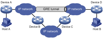
When the hop count between two terminals exceeds 15, the terminals cannot communicate with each other. Using GRE, you can hide some hops so as to enlarge the scope of the network.
VPN creation by connecting discontinuous subnets
Figure 6 Connect discontinuous subnets with a tunnel to form a VPN
In the example as shown in Figure 6, Group 1 and Group 2 running Novell IPX are deployed in different cities. They can constitute a trans-WAN virtual private network (VPN) through the tunnel.
GRE-IPsec tunnel application
Figure 7 GRE-IPsec tunnel application
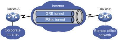
GRE can work with IPsec, allowing data packets like routing protocol, voice, and video packets to be encapsulated by GRE and then encrypted by IPsec to improve security of data transmission in a tunnel.
Protocols and standards
· RFC 1701, Generic Routing Encapsulation (GRE)
· RFC 1702, Generic Routing Encapsulation over IPv4 networks
· RFC 2784, Generic Routing Encapsulation (GRE)
Configuring a GRE over IPv4 tunnel
Configuration guidelines
· The source address and destination address of a tunnel uniquely identify a path. They must be configured at both ends of the tunnel and the source address at one end must be the destination address at the other end and vice versa.
· Tunnel interfaces using the same encapsulation protocol must have different source addresses and destination addresses.
· If you configure a source interface for a tunnel interface, the tunnel interface takes the primary IP address of the source interface as its source address.
· When configuring a route through the tunnel, you are not allowed to set up a static route whose destination address is in the subnet of the tunnel interface. Instead, you can do one of the following:
? Configure a static route, using the address of the subnet that the original packet is destined for as its destination address and the address of the peer tunnel interface as its next hop.
? Enable a dynamic routing protocol on both the tunnel interface and the router interface connecting the private network, so that the dynamic routing protocol can establish a routing entry that allows the tunnel to forward packets through the tunnel.
Configuration prerequisites
On each of the peer devices, configure an IP address for the interface to be used as the source interface of the tunnel interface (which can be a, for example, VLAN interface, Ethernet interface, or loopback interface), and make sure that this interface can normally communicate with the interface used as the source interface of the tunnel interface on the peer device.
Configuration procedure
To configure a GRE over IPv4 tunnel:
|
Step |
Command |
Remarks |
|
1. Enter system view. |
system-view |
N/A |
|
2. Create a tunnel interface and enter tunnel interface view. |
interface tunnel interface-number |
By default, the switch has no tunnel interface. |
|
3. Configure an IPv4 address for the tunnel interface. |
ip address ip-address { mask | mask-length } |
By default, a tunnel interface has no IPv4 address. |
|
4. Set the tunnel mode to GRE over IPv4. |
tunnel-protocol gre |
Optional. The default tunnel mode is GRE over IPv4. You must configure the same tunnel mode on both ends of a tunnel. Otherwise, packet delivery will fail. |
|
5. Configure the source address or interface for the tunnel interface. |
source { ip-address | interface-type interface-number } |
By default, no source address or interface is configured for a tunnel interface. |
|
6. Configure the destination address for the tunnel interface. |
destination ip-address |
By default, no destination address is configured for a tunnel interface. |
|
7. Configure a route to direct traffic to the tunnel. |
See Layer 3—IP Routing Configuration Guide. |
Each end of the tunnel must have a route (static or dynamic) through the tunnel to the other end. |
|
8. Set an IPv6 MTU for the tunnel interface. |
ipv6 mtu mtu-size |
Optional. By default, the IPv6 MTU is 1476 bytes. |
|
9. Return to system view. |
quit |
N/A |
|
10. Configure the device to discard the IPv4-compatible IPv6 packets. |
tunnel discard ipv4-compatible-packet |
Optional. By default, the switch does not discard the IPv4-compatible IPv6 packets. |
|
|
NOTE: · The ipv6 mtu command applies to only IPv6 packets sent from a tunnel interface. · For information about tunnel interfaces and more configuration commands in a tunnel interface, see the chapter “Configuring tunneling.” · For information about commands interface tunnel, tunnel-protocol, source, and destination, see Layer 3—IP Services Command Reference. |
Displaying and maintaining GRE
|
Task |
Command |
Remarks |
|
Display information about a specific tunnel interface or all tunnel interfaces. |
display interface tunnel [ number ] [ | { begin | exclude | include } regular-expression ] |
Available in any view |
|
Display IPv6 information about a specific tunnel interface or all tunnel interfaces. |
display ipv6 interface tunnel [ number ] [ brief ] [ | { begin | exclude | include } regular-expression ] |
Available in any view |
|
|
NOTE: For more information about commands display interface tunnel, and display ipv6 interface tunnel, see Layer 3—IP Services Command Reference. |
GRE over IPv4 tunnel configuration examples
|
|
NOTE: By default, Ethernet interfaces, VLAN interfaces, and aggregate interfaces are in DOWN state. To configure such an interface, first use the undo shutdown command to bring the interface up. |
GRE over IPv4 tunnel configuration example 1
Network requirements
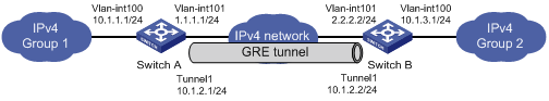
Switch A and Switch B are interconnected through the Internet. Two private IPv4 subnets Group 1 and Group 2 are interconnected through a GRE tunnel between the two switches.
Configuration procedure
|
|
NOTE: Before the configuration, make sure that Switch A and Switch B can reach each other. |
1. Configure Switch A.
# Configure an IPv4 address for interface GigabitEthernet 3/0/1.
<SwitchA> system-view
[SwitchA] vlan 100
[SwitchA-vlan100] port GigabitEthernet 3/0/1
[SwitchA-vlan100] quit
[SwitchA] interface vlan-interface 100
[SwitchA-Vlan-interface100] ip address 10.1.1.1 255.255.255.0
[SwitchA-Vlan-interface100] quit
# Configure an IPv4 address for interface GigabitEthernet 3/0/2, the physical interface of the tunnel.
[SwitchA] vlan 101
[SwitchA-vlan101] port GigabitEthernet 3/0/2
[SwitchA-vlan101] quit
[SwitchA] interface vlan-interface 101
[SwitchA-Vlan-interface101] ip address 1.1.1.1 255.255.255.0
[SwitchA-Vlan-interface101] quit
# Create a tunnel interface Tunnel1.
[SwitchA] interface tunnel 1
# Configure an IPv4 address for the tunnel interface.
[SwitchA-Tunnel1] ip address 10.1.2.1 255.255.255.0
# Configure the tunnel encapsulation mode as GRE over IPv4.
[SwitchA-Tunnel1] tunnel-protocol gre
# Configure a source address for the tunnel interface (IP address of the VLAN interface to which GigabitEthernet 3/0/2 belongs).
[SwitchA-Tunnel1] source vlan-interface 101
# Configure a destination address for the tunnel interface (IP address of the VLAN interface to which GigabitEthernet 3/0/2 of Switch B belongs).
[SwitchA-Tunnel1] destination 2.2.2.2
[SwitchA-Tunnel1] quit
# Configure a static route from Switch A through tunnel interface Tunnel1 to Group 2.
[SwitchA] ip route-static 10.1.3.0 255.255.255.0 tunnel 1
2. Configure Switch B.
# Configure an IPv4 address for interface GigabitEthernet 3/0/1.
<SwitchB> system-view
[SwitchB] vlan 100
[SwitchB-vlan100] port GigabitEthernet 3/0/1
[SwitchB-vlan100] quit
[SwitchB] interface vlan-interface 100
[SwitchB-Vlan-interface100] ip address 10.1.3.1 255.255.255.0
[SwitchB-Vlan-interface100] quit
# Configure an IPv4 address for interface GigabitEthernet 3/0/2, the physical interface of the tunnel.
[SwitchB] vlan 101
[SwitchB-vlan101] port GigabitEthernet 3/0/2
[SwitchB-vlan101] quit
[SwitchB] interface vlan-interface 101
[SwitchB-Vlan-interface101] ip address 2.2.2.2 255.255.255.0
[SwitchB-Vlan-interface101] quit
# Create a tunnel interface Tunnel1.
[SwitchB] interface tunnel 1
# Configure an IPv4 address for the tunnel interface.
[SwitchB-Tunnel1] ip address 10.1.2.2 255.255.255.0
# Configure the tunnel encapsulation mode as GRE over IPv4.
[SwitchB-Tunnel1] tunnel-protocol gre
# Configure a source address for the tunnel interface (IP address of the VLAN interface to which GigabitEthernet 3/0/2 belongs).
[SwitchB-Tunnel1] source vlan-interface 101
# Configure a destination address for the tunnel interface (IP address of the VLAN interface to which GigabitEthernet 3/0/2 of Switch A belongs).
[SwitchB-Tunnel1] destination 1.1.1.1
[SwitchB-Tunnel1] quit
# Configure a static route from Switch B through the tunnel interface Tunnel1 to Group 1.
[SwitchB] ip route-static 10.1.1.0 255.255.255.0 Tunnel 1
GRE over IPv4 tunnel configuration example 2
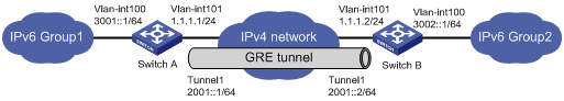
Network requirements
Switch A and Switch B are interconnected through the Internet. Two private IPv6 subnets Group 1 and Group 2 are interconnected through a GRE tunnel between the two switches.
Figure 9 Network diagram
Configuration procedure
|
|
NOTE: Before the configuration, make sure that Switch A and Switch B can reach each other. |
1. Configure Switch A.
# Configure interface GigabitEthernet 3/0/1.
<SwitchA> system-view
[SwitchA] ipv6
[SwitchA] vlan 100
[SwitchA-vlan100] port GigabitEthernet 3/0/1
[SwitchA-vlan100] quit
[SwitchA] interface vlan-interface 100
[SwitchA-Vlan-interface100] ipv6 address 3001::1 64
[SwitchA-Vlan-interface100] quit
# Configure interface GigabitEthernet 3/0/2, the physical interface of the tunnel.
[SwitchA] vlan 101
[SwitchA-vlan101] port GigabitEthernet 3/0/2
[SwitchA-vlan101] quit
[SwitchA] interface vlan-interface 101
[SwitchA-Vlan-interface101] ip address 1.1.1.1 255.255.255.0
[SwitchA-Vlan-interface101] quit
# Create a tunnel interface Tunnel1.
[SwitchA] interface tunnel 1
# Configure an IPv6 address for the tunnel interface.
[SwitchA-Tunnel1] ipv6 address 2001::1 64
# Configure the tunnel encapsulation mode as GRE over IPv4.
[SwitchA-Tunnel1] tunnel-protocol gre
# Configure a source address for the tunnel interface (IP address of the VLAN interface to which GigabitEthernet 3/0/2 belongs).
[SwitchA-Tunnel1] source 1.1.1.1
# Configure a destination address for the tunnel interface (IP address of the VLAN interface to which GigabitEthernet 3/0/2 of Switch B belongs).
[SwitchA-Tunnel1] destination 1.1.1.2
[SwitchA-Tunnel1] quit
# Configure a static route from Switch A through tunnel interface Tunnel1 to Group 2.
[SwitchA] ipv6 route-static 3002:: 64 tunnel 1
2. Configure Switch B.
# Configure interface GigabitEthernet 3/0/1.
<SwitchB> system-view
[SwitchB] ipv6
[SwitchB] vlan 100
[SwitchB-vlan100] port GigabitEthernet 3/0/1
[SwitchB-vlan100] quit
[SwitchB] interface vlan-interface 100
[SwitchB-Vlan-interface100] ipv6 address 3002::1 64
[SwitchB-Vlan-interface100] quit
# Configure interface GigabitEthernet 3/0/2, the physical interface of the tunnel.
[SwitchB] vlan 101
[SwitchB-vlan101] port GigabitEthernet 3/0/2
[SwitchB-vlan101] quit
[SwitchB] interface vlan-interface 101
[SwitchB-Vlan-interface101] ip address 1.1.1.2 255.255.255.0
[SwitchB-Vlan-interface101] quit
# Create a tunnel interface Tunnel1.
[SwitchB] interface tunnel 1
# Configure an IPv6 address for the tunnel interface.
[SwitchB-Tunnel1] ipv6 address 2001::2 64
# Configure the tunnel encapsulation mode as GRE over IPv4.
[SwitchB-Tunnel1] tunnel-protocol gre
# Configure a source address for the tunnel interface (IP address of the VLAN interface to which GigabitEthernet 3/0/2 belongs).
[SwitchB-Tunnel1] source 1.1.1.2
# Configure a destination address for the tunnel interface (IP address of the VLAN interface to which GigabitEthernet 3/0/2 of Switch A belongs).
[SwitchB-Tunnel1] destination 1.1.1.1
[SwitchB-Tunnel1] quit
# Configure a static route from Switch B through tunnel interface Tunnel1 to Group 1.
[SwitchB] ipv6 route-static 3001:: 64 Tunnel 1
Troubleshooting GRE
The key to configuring GRE is to keep the configurations consistent. This section analyzes one type of fault for illustration, with the scenario shown in Figure 10.
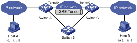
Symptom: The interfaces at both ends of the tunnel are configured correctly and can ping each other, but Host A and Host B cannot ping each other.
Solution:
· On Switch A and Switch C, execute the display ip routing-table command in any view respectively. On Switch A, observe whether there is a route from Switch A through Tunnel 0 to 10.2.0.0/16. On Switch C, observe whether there is a route from Switch C through Tunnel 0 to 10.1.0.0/16.
· If an expected static route is missing, use the ip route-static command in system view to configure. For example, configure a static route on Switch A as follows:
[SwitchA] ip route-static 10.2.0.0 255.255.0.0 tunnel 0