- Table of Contents
-
- 06-Layer 3 - IP Services Configuration Guide
- 00-Preface
- 01-ARP Configuration
- 02-IP Addressing Configuration
- 03-DHCP Configuration
- 04-DNS Configuration
- 05-NAT Configuration
- 06-IP Forwarding Basics Configuration
- 07-Adjacency Table Configuration
- 08-IP Performance Optimization Configuration
- 09-UDP Helper Configuration
- 10-IPv6 Basics Configuration
- 11-DHCPv6 Configuration
- 12-IPv6 DNS Configuration
- 13-Tunneling Configuration
- 14-GRE Configuration
- Related Documents
-
| Title | Size | Download |
|---|---|---|
| 01-ARP Configuration | 266.88 KB |
Contents
ARP address resolution process
Configuring a static ARP entry
Configuring a multi-port ARP entry
Configuring the maximum number of dynamic ARP entries for an interface
Setting the age timer for dynamic ARP entries
Enabling dynamic ARP entry check
Enabling natural mask support for ARP requests
Displaying and maintaining ARP
Static ARP entry configuration example
Multi-port ARP entry configuration example
Introduction to gratuitous ARP
Displaying and maintaining proxy ARP
Proxy ARP configuration examples
Proxy ARP configuration example
Local proxy ARP configuration example in case of port isolation
Local proxy ARP configuration example in super VLAN
|
|
NOTE: The switch supports two operation modes: standalone (default) and IRF. For more information about IRF mode, see IRF Configuration Guide. |
ARP overview
ARP function
The Address Resolution Protocol (ARP) is used to resolve an IP address into a physical address (Ethernet MAC address, for example).
In an Ethernet LAN, a switch uses ARP to translate the IP address of the next hop to the corresponding MAC address.
ARP message format
ARP messages are classified into ARP requests and ARP replies. Figure 1 shows the format of the ARP request/reply. Numbers in the figure refer to field lengths.

An ARP message contains the following fields:
· Hardware type—The hardware address type. The value 1 represents Ethernet.
· Protocol type—The type of the protocol address to be mapped. The hexadecimal value 0x0800 represents IP.
· Hardware address length and protocol address length—Length, in bytes, of a hardware address and a protocol address. For an Ethernet address, the value of the hardware address length field is 6. For an IP(v4) address, the value of the protocol address length field is 4.
· OP—Operation code. The type of ARP message. The value 1 represents an ARP request and 2 represents an ARP reply.
· Sender hardware address—Hardware address of the switch sending the message.
· Sender protocol address—Protocol address of the switch sending the message.
· Target hardware address—Hardware address of the switch the message is being sent to.
· Target protocol address—Protocol address of the switch the message is being sent to.
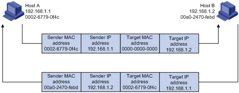
ARP address resolution process
If Host A and Host B are on the same subnet and Host A sends a packet to Host B:
1. Host A looks in its ARP table to see whether there is an ARP entry for Host B. If yes, Host A uses the MAC address in the entry to encapsulate the IP packet into a data link layer frame and sends the frame to Host B.
2. If Host A finds no entry for Host B, Host A buffers the packet and broadcasts an ARP request using the following information:
¡ Source IP address and source MAC address—Host A’s IP address and MAC address
¡ Target IP address—Host B’s IP address
¡ Target MAC address—An all-zero MAC address
Because the ARP request is broadcast, all hosts on this subnet can receive the request, but only the requested host (Host B) will process the request.
3. Host B compares its own IP address with the target IP address in the ARP request. If they are the same, Host B
a. Adds the sender IP address and sender MAC address to its ARP table.
b. Encapsulates its MAC address into an ARP reply.
c. Unicasts the reply to Host A.
4. After receiving the ARP reply, Host A
a. Adds the MAC address of Host B to its ARP table.
b. Encapsulates the MAC address into the packet and sends it to Host B.
Figure 2 ARP address resolution process
If Host A and Host B are not on the same subnet:
1. Host A sends an ARP request to the gateway. The target IP address in the ARP request is the IP address of the gateway.
2. After obtaining the MAC address of the gateway from an ARP reply, Host A sends the packet to the gateway.
3. If the gateway maintains the ARP entry of Host B, it forwards the packet to Host B directly; if not, it broadcasts an ARP request, in which the target IP address is the IP address of Host B.
4. After obtaining the MAC address of Host B, the gateway sends the packet to Host B.
ARP table
After obtaining the destination MAC address, the switch adds the IP-to-MAC mapping into its own ARP table. This mapping is used for forwarding packets with the same destination in future.
An ARP table contains dynamic and static ARP entries.
Dynamic ARP entry
A dynamic entry is automatically created and maintained by ARP. It can age out, be updated by a new ARP packet, or be overwritten by a static ARP entry. A dynamic ARP entry is removed when its age timer expires or the interface goes down.
Static ARP entry
A static ARP entry is manually configured and maintained. It does not age out and cannot be overwritten by any dynamic ARP entry.
Static ARP entries protect communication between devices, because attack packets cannot modify the IP-to-MAC mapping in a static ARP entry.
Static ARP entries can be classified into long, short, and multi-port ARP entries.
· A long static ARP entry can be directly used to forward packets. When configuring a long static ARP entry, you must configure a VLAN and outbound interface for the entry in addition to the IP address and MAC address.
· A short static ARP entry has only an IP address and a MAC address configured. It cannot be directly used for forwarding data if the outbound interface is a VLAN interface. If a short static ARP entry matches an IP packet to be forwarded, the switch sends an ARP request first. If the source IP and MAC addresses in the received ARP reply are the same as the IP and MAC addresses of the short static ARP entry, the switch adds the interface receiving the ARP reply into the short static ARP entry. Then the entry can be used for forwarding IP packets.
· A multi-port ARP entry is generated when the MAC address in a short static ARP entry is the same as that in a multicast or multi-port unicast MAC address entry. A device can use the multi-port ARP entry to send IP packets throughout multiple ports.
|
|
NOTE: · Usually ARP dynamically resolves IP addresses to MAC addresses, without manual intervention. · To allow communication with a host by using a fixed IP-to-MAC mapping, configure a short static ARP entry for it. To allow communication with a host through a specific interface in a specific VLAN by using a fixed IP-to-MAC mapping, configure a long static ARP entry for it. |
Configuring ARP
Configuring a static ARP entry
A static ARP entry is effective when the switch works normally. However, when a VLAN or VLAN interface is deleted, any static ARP entry corresponding to it will also be deleted (if it is a long static ARP entry) or will become unresolved (if it is a short and resolved static ARP entry).
To configure a static ARP entry:
|
Step |
Command |
Remarks |
|
1. Enter system view. |
system-view |
N/A |
|
2. Configure a static ARP entry. |
·
Configure a long static ARP entry: ·
Configure a short static ARP entry: |
Use either command |
|
CAUTION: · The vlan-id argument must be the ID of an existing VLAN which corresponds to the ARP entries. The Ethernet interface following the argument must belong to that VLAN. A VLAN interface must be created for the VLAN. · The IP address of the VLAN interface of the VLAN specified by the vlan-id argument must belong to the same network segment as the IP address specified by the ip-address argument. |
Configuring a multi-port ARP entry
For a multi-port ARP entry, the multicast or multi-port unicast MAC address entry specifies the VLAN ID and outbound ports, and the short static ARP entry specifies the VPN and the IP address. A multi-port ARP entry is never overwritten by a dynamic, short static, or long static ARP entry.
To configure a multi-port ARP entry:
|
Step |
Command |
Remarks |
|
1. Enter system view. |
system-view |
N/A |
|
2. Configure a multicast or multi-port unicast MAC address entry. |
· Configure a multi-port unicast MAC address entry: ·
Configure a multicast MAC address entry: |
Use either command. |
|
3. Configure a short static ARP entry. |
arp static ip-address mac-address [ vpn-instance vpn-instance-name ] |
The mac-address in the short static ARP entry must be the same as that in the multicast or multi-port unicast MAC address entry. |
|
|
CAUTION: · The multi-port ARP entry does not take effect if the corresponding VLAN interface is not created, is down, or does not match the specified VPN. Thus, packets matching it are discarded. It takes effect when the VLAN interface is up and matches the specified VPN. · The short static ARP entry uses its MAC address to find a matching multicast or multi-port unicast MAC address entry. If the MAC address exists in multiple VLANs, the short static ARP entry uses the MAC address that has the smallest VLAN ID to generate the multi-port ARP entry. · When multi-port ARP entries reach the maximum number, the short static ARP entry and the matching multicast or multi-port unicast MAC address entry cannot generate a multi-port ARP entry. In addition, they cannot automatically generate the multi-port ARP entry when any existing multi-port ARP entries are removed. You need to manually configure them again. · For more information about the multi-port unicast MAC address entry, see the mac-address multiport command in Layer 2—LAN Switching Command Reference. For more information about the multicast MAC address entry, see the mac-address multicast command in IP Multicast Command Reference. · When an Ethernet interface is added to an aggregate group, you can configure the multicast or multi-port unicast MAC address entry only in the aggregate interface view corresponding to the aggregate group. Otherwise, you cannot configure them. |
Configuring the maximum number of dynamic ARP entries for an interface
An interface can dynamically learn ARP entries, so it may hold too many ARP entries. To solve this problem, you can set the maximum number of dynamic ARP entries that an interface can learn. When the maximum number is reached, the interface stops learning ARP entries.
To set the maximum number of dynamic ARP entries that an interface can learn:
|
Step |
Command |
Remarks |
|
1. Enter system view. |
system-view |
N/A |
|
2. Enter interface view. |
interface interface-type interface-number |
N/A |
|
3. Set the maximum number of dynamic ARP entries that the interface can learn. |
arp max-learning-num number |
Optional. By default, the maximum number of ARP entries that an interface can learn is the maximum remaining resource of the switch. If the value of the number argument is set to 0, the interface is disabled from learning dynamic ARP entries. |
|
|
NOTE: If you set the maximum numbers of dynamic ARP entries that a Layer 2 interface and its VLAN interface can learn, the smaller number takes effect. |
Setting the age timer for dynamic ARP entries
Each dynamic ARP entry in the ARP table has a limited lifetime, called age timer. The age timer of a dynamic ARP entry is reset each time the dynamic ARP entry is used. Dynamic ARP entries that are not used before their age timers expire are deleted from the ARP table. You can adjust the age timers for dynamic ARP entries according to the actual network condition.
To set the age timer for dynamic ARP entries:
|
Step |
Command |
Remarks |
|
1. Enter system view. |
system-view |
N/A |
|
2. Set the age timer for dynamic ARP entries. |
arp timer aging aging-time |
Optional. 20 minutes by default. |
Enabling dynamic ARP entry check
The dynamic ARP entry check function controls whether the switch supports dynamic ARP entries with multicast MAC addresses.
When dynamic ARP entry check is enabled, the switch cannot learn dynamic ARP entries containing multicast MAC addresses.
When dynamic ARP entry check is disabled, the switch can learn dynamic ARP entries containing multicast MAC addresses.
To enable dynamic ARP entry check:
|
Step |
Command |
Remarks |
|
1. Enter system view. |
system-view |
N/A |
|
2. Enable dynamic ARP entry check. |
arp check enable |
Optional. Enabled by default. A switch does not learn any ARP entry with a multicast MAC address. |
Enabling natural mask support for ARP requests
This feature enables the switch to learn the sender IP and MAC address in a received ARP request whose sender IP address is on the same classful network as but a different subnet from the IP address of the receiving interface. A classful network refers to a class A, B, or C network.
For example, VLAN-interface 10 with IP address 10.10.10.5/24 receives an ARP request from 10.11.11.1/8. Because the subnet address calculated by the AND operation of 10.11.11.1 and the receiving interface’s 24-bit subnet mask is not on the subnet 10.10.10.5/24, VLAN-interface 10 cannot process the ARP packet.
With this feature enabled, the switch calculates the subnet address by using the default mask of the class A network where 10.10.10.5/24 resides. Because 10.10.10.5/24 is on the same class A network as 10.11.11.1/8, VLAN-interface 10 can learn the sender IP and MAC addresses in the request.
To enable natural mask support for ARP requests:
|
Step |
Command |
Remarks |
|
1. Enter system view. |
system-view |
N/A |
|
2. Enable natural mask support for ARP requests. |
naturemask-arp enable |
Disabled by default |
Displaying and maintaining ARP
|
Task |
Command |
Remarks |
|
Display ARP entries in the ARP table (in standalone mode). |
display arp [ [ all | dynamic | static ] [ slot slot-number ] | vlan vlan-id | interface interface-type interface-number ] [ count | verbose ] [ | { begin | exclude | include } regular-expression ] |
Available in any view |
|
Display ARP entries in the ARP table (in IRF mode). |
display arp [ [ all | dynamic | static ] [ chassis chassis-number slot slot-number ] | vlan vlan-id | interface interface-type interface-number ] [ count | verbose ] [ | { begin | exclude | include } regular-expression ] |
Available in any view |
|
Display the ARP entry for a specified IP address (in standalone mode). |
display arp ip-address [ slot slot-number ] [ verbose ] [ | { begin | exclude | include } regular-expression ] |
Available in any view |
|
Display the ARP entry for a specified IP address (in IRF mode). |
display arp ip-address [ chassis chassis-number slot slot-number ] [ verbose ] [ | { begin | exclude | include } regular-expression ] |
Available in any view |
|
Display the ARP entries for a specified VPN instance. |
display arp vpn-instance vpn-instance-name [ | { begin | exclude | include } regular-expression | count ] |
Available in any view |
|
Display the age timer for dynamic ARP entries. |
display arp timer aging [ | { begin | exclude | include } regular-expression ] |
Available in any view |
|
Clear ARP entries from the ARP table (in standalone mode). |
reset arp { all | dynamic | static | slot slot-number | interface interface-type interface-number } |
Available in user view |
|
Clear ARP entries from the ARP table (in IRF mode). |
reset arp { all | dynamic | static | chassis chassis-number slot slot-number | interface interface-type interface-number } |
Available in user view |
|
|
NOTE: Clearing ARP entries from the ARP table may cause communication failures. |
ARP configuration example
Static ARP entry configuration example
|
|
NOTE: By default, the Ethernet interface, VLAN interfaces, and aggregate interfaces are down. Before configuring them, bring them up with the undo shutdown command. |
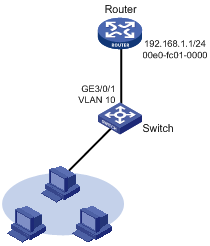
Network requirements
As shown in Figure 3, hosts are connected to Switch, which is connected to Router through interface GigabitEthernet 3/0/1 belonging to VLAN 10.The IP address of Router is 192.168.1.1/24. The MAC address of Router is 00e0-fc01-0000.
To enhance communication security for Router and Switch, static ARP entries are configured on Switch.
Configuration procedure
Configure Switch
# Create VLAN 10.
<Switch> system-view
[Switch] vlan 10
[Switch-vlan10] quit
# Add interface GigabitEthernet 3/0/1 to VLAN 10.
[Switch] interface GigabitEthernet 3/0/1
[Switch- GigabitEthernet3/0/1] port access vlan 10
[Switch- GigabitEthernet3/0/1] quit
# Create interface VLAN-interface 10 and configure its IP address.
[Switch] interface vlan-interface 10
[Switch-vlan-interface10] ip address 192.168.1.2 24
[Switch-vlan-interface10] quit
# Configure a static ARP entry that has IP address 192.168.1.1, MAC address 00e0-fc01-0000, and output interface GigabitEthernet 3/0/1 in VLAN 10.
[Switch] arp static 192.168.1.1 00e0-fc01-0000 10 GigabitEthernet3/0/1
# View information about static ARP entries.
[Switch] display arp static
Type: S-Static D-Dynamic A-Authorized
IP Address MAC Address VLAN ID Interface Aging Type
192.168.1.1 00e0-fc01-0000 10 GE3/0/1 N/A S
Multi-port ARP entry configuration example
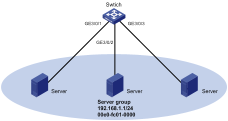
Network requirements
As shown in Figure 4, the switch connects to the server group (with three servers) through interfaces GigabitEthernet 3/0/1, GigabitEthernet 3/0/2, and GigabitEthernet 3/0/3 in VLAN 10. The server group shares the IP address 192.168.1.1/24 and MAC address 00e0-fc01-0000.
Configure a multi-port ARP entry to send IP packets with destination IP address 192.168.1.1 to the three servers.
Configuring the switch
# Create VLAN 10.
<Switch> system-view
[Switch] vlan 10
[Switch-vlan10] quit
# Add interfacesGigabitEthernet 3/0/1, GigabitEthernet 3/0/2, and GigabitEthernet 3/0/3 to VLAN 10.
[Switch] interface GigabitEthernet 3/0/1
[Switch-GigabitEthernet3/0/1] port access vlan 10
[Switch-GigabitEthernet3/0/1] quit
[Switch] interface GigabitEthernet 3/0/2
[Switch-GigabitEthernet3/0/2] port access vlan 10
[Switch-GigabitEthernet3/0/2] quit
[Switch] interface GigabitEthernet 3/0/3
[Switch-GigabitEthernet3/0/3] port access vlan 10
[Switch-GigabitEthernet3/0/3] quit
# Create interface VLAN-interface 10 and specify its IP address.
[Switch] interface vlan-interface 10
[Switch-vlan-interface10] ip address 192.168.1.2 24
[Switch-vlan-interface10] quit
# Configure a multi-port unicast MAC address entry that has MAC address 00e0-fc01-0000, and output ports GigabitEthernet 3/0/1, GigabitEthernet3/0/2, and GigabitEthernet 3/0/3 in VLAN 10.
[Switch] mac-address multiport 00e0-fc01-0000 interface GigabitEthernet 3/0/1 to GigabitEthernet 3/0/3 vlan 10
# Configure a short static ARP entry with IP address 192.168.1.1 and MAC address 00e0-fc01-0000.
[Switch] arp static 192.168.1.1 00e0-fc01-0000
# Display ARP information.
[Switch] display arp
Type: S-Static D-Dynamic A-Authorized M-Multiport
IP Address MAC Address VLAN ID Interface Aging Type
192.168.1.1 00e0-fc01-0000 N/A N/A N/A M
Introduction to gratuitous ARP
In a gratuitous ARP packet, the sender IP address and the target IP address are both the IP address of the switch issuing the packet, the sender MAC address is the MAC address of the switch, and the target MAC address is the broadcast address ff:ff:ff:ff:ff:ff.
A switch implements the following functions by sending gratuitous ARP packets:
· Determining whether its IP address is already used by another switch. If the IP address is already used, the switch issuing the gratuitous ARP packet will be informed by an ARP reply of the conflict.
· Informing other switches about the change of its MAC address so that they can update their ARP entries.
Enabling learning of gratuitous ARP packets
With this feature enabled, a switch receiving a gratuitous ARP packet adds the sender IP and MAC addresses carried in the packet to its ARP table if no corresponding ARP entry exists. If a corresponding ARP entry is found, the switch updates the ARP entry.
After this feature is disabled, the switch will use the address information in the received gratuitous ARP packets to update the existing ARP entries only, but not to create new ARP entries.
Configuring periodic sending of gratuitous ARP packets
Enabling a switch to periodically send gratuitous ARP packets helps downstream switches update their corresponding ARP entries or MAC entries in time. This feature can be used to:
· Prevent gateway spoofing
If an attacker sends forged gratuitous ARP packets to the hosts on a network, the traffic destined for the gateway from the hosts is sent to the attacker instead. As a result, the hosts cannot access the external network.
To prevent such gateway spoofing attacks, you can enable the gateway to send gratuitous ARP packets containing its primary IP address or one of its manually configured secondary IP addresses at a specific interval. In this way, each host can learn correct gateway address information.
· Prevent ARP entries from being aged out
If network traffic is heavy or the CPU utility is high on a host, ARP packets received may be discarded or cannot be processed in time. Eventually, the dynamic ARP entries on the receiving host will be aged out, and the traffic between the host and the corresponding switches will be interrupted until the host creates the ARP entries again.
To prevent such a problem, you can enable the gateway to send gratuitous ARP packets periodically. The gratuitous ARP packets contain the gateway's primary IP address or one of its manually configured secondary IP addresses. In this way, the receiving host can update ARP entries in time and thus ensure traffic continuity.
· Prevent the virtual IP address of a VRRP group from being used by a host
The master router of a VRRP group can periodically send gratuitous ARP packets to the hosts on the local network, so that the hosts can update local ARP entries and avoid using the virtual IP address of the VRRP group.
If the virtual IP address of the VRRP group is associated with a virtual MAC address, the sender MAC address in the gratuitous ARP packet takes the virtual MAC address of the virtual router. If the virtual IP address of the VRRP group is associated with the real MAC address of an interface, the sender MAC address in the gratuitous ARP packet takes the MAC address of the interface on the master router in the VRRP group.
· Update MAC entries of switches in the VLANs having ambiguous VLAN termination configured
In VRRP configuration, if ambiguous VLAN termination is configured for many VLANs and VRRP groups, interfaces configured with VLAN termination need to be disabled from transmitting broadcast/multicast packets and a VRRP control VLAN needs to be configured so that VRRP advertisements can be transmitted within the control VLAN only. In such cases, you can enable periodic sending of gratuitous ARP packets containing the VRRP virtual IP address, and the primary IP address or a manually configured secondary IP address of the sending interface on the subinterfaces. In this way, when a VRRP failover occurs, switches in the VLANs having ambiguous VLAN termination configured can use the gratuitous ARP packets to update their corresponding MAC entries in time.
|
|
NOTE: For more information about VRRP, see High Availability Configuration Guide. |
Configuring gratuitous ARP
To configure gratuitous ARP:
|
Command |
Remarks |
|
|
1. Enter system view. |
system-view |
N/A |
|
2. Enable the gratuitous ARP packet learning function. |
gratuitous-arp-learning enable |
Enabled by default. |
|
3. Enable the switch to send gratuitous ARP packets when receiving ARP requests from another network segment. |
gratuitous-arp-sending enable |
Optional. By default, a switch does not send gratuitous ARP packets upon receiving ARP requests from another network segment. |
Proxy ARP overview
Proxy ARP includes common proxy ARP and local proxy ARP.
· Common proxy ARP allows communication when a sending host considers the receiving host to be on the same subnet, but the receiving host actually resides on a different subnet.
· Local proxy ARP allows communication between hosts that reside on the same subnet but are isolated at Layer 2.
In both cases, a device located between the two hosts must respond to the request with the MAC address of the receiving interface to allow Layer 3 communication between the two hosts. This is achieved by proxy ARP, which hides the physical details of the network.
|
|
NOTE: The term proxy ARP in the following sections of this chapter refers to common proxy ARP unless otherwise specified. |
Proxy ARP
Proxy ARP allows hosts that reside on different subnets to communicate.
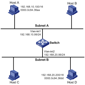
As shown in Figure 5, Router connects to two subnets through VLAN-interface 10 and VLAN-interface 20. The IP addresses of the two interfaces are 192.168.10.99/24 and 192.168.20.99/24, which belong to different subnets. However, Host A and Host B have the same prefix 192.168.0.0 assigned, and thus consider they are on the same subnet.
Figure 5 Application environment of proxy ARP
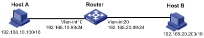
Because Host A considers that Host B is on the same network, it sends an ARP request for the MAC address of Host B. However, Host B cannot receive this request because it is in a different broadcast domain.
You can solve the problem by enabling proxy ARP on Router, so that Router can reply to the ARP request from Host A with the MAC address of VLAN-interface 10, and forward packets sent from Host A to Host B. Router acts as a proxy of Host B.
A main advantage of proxy ARP is that it is added on a single router without disturbing routing tables of other routers in the network. Proxy ARP acts as the gateway for IP hosts that are not configured with a default gateway or do not have routing capability.
Local proxy ARP
As shown in Figure 6, Host A and Host B belong to VLAN 2, but are isolated at Layer 2. Host A is connected with GigabitEthernet 3/0/1 and Host B is connected with GigabitEthernet 3/0/2. Enable local proxy ARP on Router to allow Layer 3 communication between the two hosts.
Figure 6 Application environment of local proxy ARP
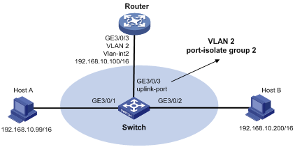
Enable local proxy ARP in one of the following cases:
· Hosts connected to different isolated layer 2 ports in the same VLAN need to communicate at Layer 3.
· If a super VLAN is configured, hosts in different sub VLANs of the super VLAN need to communicate at Layer 3.
Enabling proxy ARP
To enable proxy ARP in VLAN interface view/Layer 3 Ethernet interface view/Layer 3 Ethernet subinterface view/Layer 3 aggregate interface view/Layer 3 aggregate subinterface view:
|
Step |
Command |
Remarks |
|
1. Enter system view. |
system-view |
N/A |
|
2. Enter interface view. |
interface interface-type interface-number |
N/A |
|
3. Enable proxy ARP. |
proxy-arp enable |
Disabled by default |
To enable local proxy ARP in VLAN interface view/Layer 3 Ethernet interface view/ Layer 3 Ethernet subinterface view/Layer 3 aggregate interface view/Layer 3 aggregate subinterface view:
|
Step |
Command |
Remarks |
|
1. Enter system view. |
system-view |
N/A |
|
2. Enter interface view. |
interface interface-type interface-number |
N/A |
|
3. Enable local proxy ARP. |
local-proxy-arp enable [ ip-range startIP to endIP ] |
Disabled by default |
Displaying and maintaining proxy ARP
|
Task |
Command |
Remarks |
|
Display whether proxy ARP is enabled. |
display proxy-arp [ interface interface-type interface-number ] [ | { begin | exclude | include } regular-expression ] |
Available in any view |
|
Display whether local proxy ARP is enabled. |
display local-proxy-arp [ interface interface-type interface-number ] [ | { begin | exclude | include } regular-expression ] |
Available in any view |
Proxy ARP configuration examples
|
|
NOTE: By default, the Ethernet interface, VLAN interfaces, and aggregate interfaces are down. Before configuring them, bring them up with the undo shutdown command. |
Proxy ARP configuration example
Network requirements
As shown in Figure 7, Host A and Host D have the same IP prefix and mask (IP addresses of Host A and Host D are 192.168.10.100/16 and 192.168.20.200/16 respectively), but are located on different subnets (Host A belongs to VLAN 1 and Host D belongs to VLAN 2). As a result, Host D cannot receive or respond to any ARP request from Host A.
You must configure proxy ARP on the router to enable communication between Host A and Host D.
Configuration procedure
# Create VLAN 2.
<Switch> system-view
[Switch] vlan 2
[Switch-vlan2] quit
# Specify the IP address of interface VLAN-interface 1.
[Switch] interface vlan-interface 1
[Switch-Vlan-interface1] ip address 192.168.10.99 255.255.255.0
# Enable proxy ARP on interface VLAN-interface 1.
[Switch-Vlan-interface1] proxy-arp enable
[Switch-Vlan-interface1] quit
# Specify the IP address of interface VLAN-interface 2.
[Switch] interface vlan-interface 2
[Switch-Vlan-interface2] ip address 192.168.20.99 255.255.255.0
# Enable proxy ARP on interface VLAN-interface 2.
[Switch-Vlan-interface2] proxy-arp enable
[Switch-Vlan-interface2] quit
After completing preceding configurations, use the ping command to verify the connectivity between Host A and Host D.
Local proxy ARP configuration example in case of port isolation
Network requirements
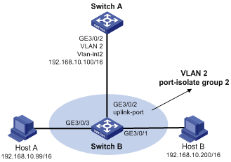
As shown in Figure 8, Host A and Host B belong to the same VLAN, and are connected to GigabitEthernet 3/0/3 and GigabitEthernet 3/0/1 of Switch respectively. Switch B is connected to Switch A via GigabitEthernet 3/0/2. On Switch B, Layer 2 and Layer 3 port isolation are configured on GigabitEthernet 3/0/3 and GigabitEthernet 3/0/1. Enable proxy ARP on Switch A to allow communication between Host A and Host B.
|
|
NOTE: In this configuration example, suppose all traffic between the hosts is blocked, so you need to configure local proxy ARP on VLAN-interface 2 of Switch A to enable communication between Host A and Host B. If the two ports (GigabitEthernet 3/0/3 and GigabitEthernet 3/0/1) on Switch B are isolated only at Layer 2, you can enable communication between the two hosts by configuring local proxy ARP directly on VLAN-interface 2 of Switch B. |
Configuration procedure
1. Configure Switch B:
# Add GigabitEthernet 3/0/3, GigabitEthernet 3/0/1 and GigabitEthernet 3/0/2 to VLAN 2. Host A and Host B are isolated and unable to exchange Layer 2 packets.
<SwitchB> system-view
[SwitchB] port-isolate group 2
[SwitchB] vlan 2
[SwitchB-vlan2] port gigabitethernet 3/0/3
[SwitchB-vlan2] port gigabitethernet 3/0/1
[SwitchB-vlan2] port gigabitethernet 3/0/2
[SwitchB-vlan2] quit
[SwitchB] interface gigabitethernet 3/0/3
[SwitchB-GigabitEthernet3/0/3] port-isolate enable group 2
[SwitchB-GigabitEthernet3/0/3] interface gigabitethernet 3/0/1
[SwitchB-GigabitEthernet3/0/1] port-isolate enable group 2
[SwitchB-GigabitEthernet3/0/1] interface gigabitethernet 3/0/2
[SwitchB-GigabitEthernet3/0/2] port-isolate uplink-port group 2
2. Configure Switch A:
# Create VLAN 2, and add GigabitEthernet 3/0/2 to VLAN 2.
<SwitchA> system-view
[SwitchA] vlan 2
[SwitchA-vlan2] port gigabitethernet 3/0/2
[SwitchA-vlan2] quit
[SwitchA] interface vlan-interface 2
[SwitchA-Vlan-interface2] ip address 192.168.10.100 255.255.0.0
The ping operation from Host A to Host B is unsuccessful because they are isolated at Layer 2.
# Configure local proxy ARP to let Host A and Host B communicate at Layer 3.
[SwitchA-Vlan-interface2] local-proxy-arp enable
The ping operation from Host A to Host B is successful after the configuration.
Local proxy ARP configuration example in super VLAN
Network requirements
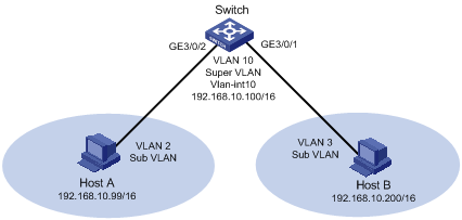
As shown in Figure 9, a super VLAN, VLAN 10, is created, with the interface IP address being 192.168.10.100/16. Sub-VLANs (VLAN 2 and VLAN 3) are created. GigabitEthernet 3/0/2 belongs to VLAN 2 and GigabitEthernet 3/0/1 belongs to VLAN 3.
As Host A and Host B belong to different Sub-VLANs, they are isolated at Layer 2. Configure local proxy ARP on the switch to implement Layer 3 communication between Host A and Host B.
Configuration procedure
# Create the super VLAN and the sub-VLANs. Add GigabitEthernet 3/0/2 to VLAN 2 and GigabitEthernet 3/0/1 to VLAN 3. Configure the IP address 192.168.10.100/16 for the interface of VLAN 10.
[Switch] vlan 2
[Switch-vlan2] port gigabitethernet 3/0/2
[Switch-vlan2] quit
[Switch] vlan 3
[Switch-vlan3] port gigabitethernet 3/0/1
[Switch-vlan3] quit
[Switch] vlan 10
[Switch-vlan10] supervlan
[Switch-vlan10] interface vlan-interface 10
[Switch-Vlan-interface10] ip address 192.168.10.100 255.255.0.0
The ping operation from Host A to Host B is unsuccessful because they are isolated at Layer 2.
# Configure local proxy ARP to implement Layer 3 communication between sub-VLANs.
[Switch-Vlan-interface10] local-proxy-arp enable
The ping operation from Host A to Host B is successful after the configuration.