| Title | Size | Downloads |
|---|---|---|
| s5130s_ei-cmw710-system-r6126p53.rar | 116.31 KB | |
| S5130S_EI-CMW710-R6126P53.zip | 47.36 MB | |
| H3C S5130S_EI-CMW710-R6126P53 Release Notes.pdf | 607.49 KB | |
| H3C S5130S_EI-CMW710-R6126P53 Release Notes (Software Feature Changes).pdf | 797.70 KB |
H3C S5130S_LI-CMW710-R6126P39 Release Notes
Contents
Hardware and software compatibility matrix· 1
Upgrading restrictions and guidelines· 3
Software feature and command updates· 3
Operation changes in R6126P39· 4
Operation changes in R6126P38· 4
Operation changes in R6126P36· 4
Operation changes in R6126P35· 4
Operation changes in R6126P13· 5
Open problems and workarounds· 5
Resolved problems in R6126P39· 5
Resolved problems in R6126P38· 6
Resolved problems in R6126P36· 10
Resolved problems in R6126P35· 10
Resolved problems in R6126P13· 11
Appendix B Upgrading software· 17
System software file types· 17
Downloading software images to the master switch· 20
Upgrading the software images· 23
Upgrading from the Boot menu· 24
Accessing the extended Boot menu· 26
Upgrading Comware images from the Boot menu· 28
Upgrading Boot ROM from the Boot menu· 37
Managing files from the Boot menu· 44
Handling software upgrade failures· 47
List of Tables
Table 2 Hardware and software compatibility matrix. 1
Table 4 Technical specifications for non-PoE switch models. 13
Table 5 Software features of the S5130S-LI series. 14
Table 6 Minimum free storage space requirements. 25
Table 8 Extended Boot ROM menu options. 27
Table 9 EXTENDED ASSISTANT menu options. 28
Table 10 TFTP parameter description. 28
Table 11 FTP parameter description. 30
Table 12 TFTP parameter description. 37
Table 13 FTP parameter description. 39
This document describes the features, restrictions and guidelines, open problems, and workarounds for version S5130S_LI-CMW710-R6126P39 . Before you use this version in a live network, back up the configuration and test the version to avoid software upgrade affecting your live network.
Use this documents listed in "Related documentation."
Version information
Version number
H3C Comware Software, Version 7.1.070, Release 6126P39
Note: You can see the version number with the command display version in any view. Please see Note①.
Version history
Version number | Last version | Release Date | Release type | Remarks |
S5130S_LI-CMW710-R6126P39 | S5130S_LI-CMW710-R6126P38 | 2019-01-25 | Release version | Fixed bugs |
S5130S_LI-CMW710-R6126P38 | S5130S_LI-CMW710-R6126P36 | 2018-12-20 | Release version | Fixed bugs |
S5130S_LI-CMW710-R6126P36 | S5130S_LI-CMW710-R6126P35 | 2018-07-20 | Release version | Fixed bugs |
S5130S_LI-CMW710-R6126P35 | S5130S_LI-CMW710-R6126P13 | 2018-06-30 | Release version | Fixed bugs |
S5130S_LI-CMW710-R6126P13 | First release | 2018-05-15 | Release version | First release |
Hardware and software compatibility matrix
Table 2 Hardware and software compatibility matrix
Item | Specifications |
Product family | S5130S_LI Series |
Hardware platform | S5130S-28S-LI S5130S-52S-LI |
Minimum memory requirements | 512M |
Minimum Flash requirements | 256M |
Boot ROM version | Version 126 or higher (Note: Use the display version command in any view to view the version information. Please see Note②) |
Host software | S5130S_LI-CMW710-R6126P39.ipe |
iMC version | iMC BIMS 7.3 (E0501) iMC EAD 7.3 (E0502) iMC EIA 7.3 (E0503) iMC NTA 7.3(E0502) iMC PLAT 7.3 (E0605P06) iMC QoSM 7.3 (E0502) iMC RAM 7.3 (E0501) iMC SHM 7.3 (E0502) |
iNode version | iNode PC 7.3 (E0504) |
Web version | None |
Remarks | None |
Display the system software and Boot ROM versions of S5130S-LI:
H3C Comware Software, Version 7.1.070, Release 6126P39 --------- 注①
Copyright (c) 2004-2019 New H3C Technologies Co., Ltd. All rights reserved.
H3C S5130S-28S-LI uptime is 0 weeks, 0 days, 0 hours, 2 minutes
Last reboot reason : Cold reboot
Boot image: flash:/s5130s_li-cmw710-boot-r6126p39.bin
Boot image version: 7.1.070, Release 6126P39
Compiled Apr 13 2017 16:00:00
System image: flash:/s5130s_li-cmw710-system-r6126p39.bin
System image version: 7.1.070, Release 6126P39
Compiled Apr 13 2017 16:00:00
Feature image(s) list:
flash:/s5130s_li-cmw710-freeradius-r6126p39.bin, version: 7.1.070
Compiled Apr 13 2017 16:00:00
Slot 1:
Uptime is 0 weeks,0 days,0 hours,8 minutes
S5130S-28S-LI with 1 Processor
BOARD TYPE: S5130S-28S-LI
DRAM: 512M bytes
FLASH: 256M bytes
PCB 1 Version: VER.A
Bootrom Version: 126 ------ 注②
CPLD 1 Version: 001
Release Version: H3C S5130S-28S-LI-6126P39
Patch Version : None
Reboot Cause : ColdReboot
[SubSlot 0] 24GE+4SFP+
Upgrading restrictions and guidelines
None.
Hardware feature updates
S5130S_LI-CMW710-R6126P39
BIDI 40KM and 80KM Gigabit transceiver modules are supported.
S5130S_LI-CMW710-R6126P38
None.
S5130S_LI-CMW710-R6126P36
None.
S5130S_LI-CMW710-R6126P35
None.
S5130S_LI-CMW710-R6126P13
First release.
Software feature and command updates
For more information about the software feature and command update history, see H3C S5130S_LI-CMW710-R6126P39 Release Notes (Software Feature Changes).
MIB Updates
Item | MIB file | Module | Description |
S5130S_LI-CMW710-R6126P39 | |||
New | None | None | None |
Modified | None | None | None |
S5130S_LI-CMW710-R6126P38 | |||
New | None | None | None |
Modified | None | None | None |
S5130S_LI-CMW710-R6126P36 | |||
New | None | None | None |
Modified | None | None | None |
S5130S_LI-CMW710-R6126P35 | |||
New | None | None | None |
Modified | None | None | None |
S5130S_LI-CMW710-R6126P13 | |||
New | First release | First release | First release |
Modified | First release | First release | First release |
Operation Changes
Operation changes in R6126P39
None.
Operation changes in R6126P38
The priority order of referencing ACLs is modified for MQC, packet filter, and portal.
Before modification: Portal > packet filter > MQC
After modification: Packet filter > MQC > portal
Operation changes in R6126P36
None.
Operation changes in R6126P35
None.
Operation changes in R6126P13
First release.
Restrictions and cautions
Release 6126P39 must use BootROM 126 or a later version.
Before upgrading the software, you must fully understand the software feature changes between different software versions in H3C S5130S_LI-CMW710-R6126P39 Release Notes (Software Feature Changes) and evaluate the impacts of the software upgrade on the live network. At the same time, for more information, you can refer to the related documentation sets.
Open problems and workarounds
1. 201902020022
· Symptom: When the voice VLAN security mode is enabled and LLDP is enabled for automatic IP phone discovery, the switch drops the LLDPDUs that have voice VLAN tags, and automatic IP phone discovery does not take effect.
· Condition: This symptom might occur if the voice VLAN security mode is enabled and LLDP is enabled for automatic IP phone discovery.
· Workaround: Disable the voice VLAN security mode.
List of resolved problems
Resolved problems in R6126P39
1. 201901250098
· Symptom: On an IRF fabric, execution of the voice-vlan enable command fails for lack of resources.
· Condition: This symptom might occur if the value obtained by subtracting the number of OUI addresses from the product of the number of voice VLAN-enabled interfaces and the number of IRF member devices is larger than 56.
2. 201901250420
· Symptom: A PBR policy does not take effect on an interface if link status change occurs on another interface which is the next hop of a large number of routes.
· Condition: This symptom might occur if link status change occurs on an interface which is the next hop of a large number of routes.
3. 201901250337
· Symptom: On an IRF fabric, the MAC addresses obtained by using SNMP are inconsistent with those displayed by using the display mac-address command.
· Condition: This symptom might occur if the following conditions exist on an IRF fabric:
¡ No multichassis aggregation group is configured.
¡ MAC address synchronization is disabled.
¡ No inter-slot traffic exists.
Resolved problems in R6126P38
1. 201806150108
· Symptom: The rate information of a 100-Mbps port is displayed as 1000 Mbps.
· Condition: This symptom occurs if you execute the link-delay command on the port and set the rate of the peer port to 1000 Mbps.
2. 201812200151
· Symptom: After a PoE device is powered off and then restarted, the PoE device cannot supply power properly.
· Condition: This symptom occurs if the PoE device is installed with the PSE module LSPPSE24A, LSPPSE48A, LSPPSE16A, or LSPPSE8A.
3. 201811080865
· Symptom: The switch acting as a DHCP client cannot obtain IP addresses from an H3C DHCP server.
· Condition: This symptom occurs if the DHCP-OFFER message sent by the DHCP server uses a unicast MAC address as the destination MAC address.
4. 201811260764
· Symptom: An access node is automated and connected to a leaf node through two uplinks and the two links are automatically aggregated. However, the topology shows that there are multiple links between the access node and the leaf node, and there is no aggregate interface in the interface group of each node.
· Condition: This symptom occurs if an access node is automated and connected to a leaf node through two uplinks and the two links are automatically aggregated.
5. 201810120764
· Symptom: After a two-chassis IRF fabric reboots, MAC authentication users fail authentication on a port of the subordinate member.
· Condition: This symptom might occur if the following conditions exist:
a. The IRF member devices each have a port that is working in the userlogin-secure-or-mac port security mode.
b. The running configuration is saved and the .mdb configuration file is deleted before the IRF fabric is rebooted.
c. MAC authentication users perform authentication on the port in userlogin-secure-or-mac mode of the subordinate member after the IRF fabric reboots.
6. 201810120762
· Symptom: After the switch upgrades to the current software version and loads a text configuration file, command output shows that port security configuration becomes incorrect.
· Condition: This symptom might occur if the running configuration is saved after port security is configured and then the switch upgrades to the current software version.
7. 201809190880
· Symptom: An IP phone attached to the switch cannot communicate with the gateway.
· Condition: This symptom might occur if the port which the IP phone is attached to is shut down and then brought up after the IP phone joins a voice VLAN.
8. 201809180169
· Symptom: The following symptoms exist after the switch is rebooted:
¡ PoE-capable ports cannot supply power.
¡ In the output from the display environment command, the temperature of the last sensor is higher than the shutdown temperature threshold or displayed as --.
¡ The switch outputs the over temperature alarm.
¡ The SYS LED is red.
· Condition: This symptom might occur if the power supply priority of multiple ports is set to critical and the switch is powered off before rebooted.
9. 201809150233
· Symptom: The following symptoms exist after the switch is rebooted or has been running for a period of time:
¡ PoE-capable ports cannot supply power.
¡ In the output from the display environment command, the temperature of the last sensor is higher than the shutdown temperature threshold or displayed as --.
¡ The switch outputs the over temperature alarm.
¡ The SYS LED is red.
· Condition: This symptom might occur if the switch is powered off before rebooted or has been running for a period of time.
10. 201809140213
· Symptom: After the switch starts up, PoE-capable ports cannot supply power, and the SYS LED becomes red.
· Condition: This symptom might occur if the switch starts up correctly.
11. 201808310515
· Symptom: When the switch has multiple ECMP routes to a destination, the MAC address entries for the next hops are incorrect.
· Condition: This symptom might occur if the switch has multiple ECMP routes to a destination.
12. 201810290223
· Symptom: Telnet login fails when the CPU is attacked by packets.
· Condition: This symptom might occur if the CPU is attacked by packets.
13. 201810220044
· Symptom: The memory is exhausted when Ethernet interfaces are repeatedly shut down and brought up.
· Condition: This symptom might occur if Ethernet interfaces are repeatedly shut down and brought up.
14. 201809210670
· Symptom: The port security process does not respond.
· Condition: This symptom might occur if LLDP requests user information from the port security module when the disableport-temporarily intrusion protection action is triggered on a port configured with port security.
15. 201804040436
· Symptom: After an IRF fabric starts up with empty configuration, ARP packets that should be forwarded are sent to the CPU.
· Condition: This symptom might occur if an IRF fabric starts up with empty configuration.
· Workaround: None.
16. 201810120112
· Symptom: When the switch is frequently accessed through SNMP, resources of the switch are exhausted and SNMP access fails.
· Condition: This symptom might occur if the switch is frequently accessed through SNMP.
17. 201810130049
· Symptom: The DHCP server stores DHCP client startup files, and the switch acts as a DHCP client. When the switch starts up with empty configuration and then connects to the DHCP server, an error message is output.
· Condition: This symptom might occur if the following conditions exist:
¡ The DHCP server stores DHCP client startup files.
¡ The switch acts as a DHCP client, and it starts up with empty configuration.
18. 201808230761
· Symptom: In the display environment command output, the temperature information for the last sensor is incorrect.
· Condition: This symptom occurs if the display environment command is used to display information about all temperature sensors on the device.
19. 201807310196
· Symptom: The device reboots unexpectedly.
· Condition: This symptom occurs if the following operations are performed:
¡ The VLAN interface for the super VLAN is bound to a VPN instance.
¡ The super VLAN is deleted after a new sub VLAN is associated with the super VLAN.
20. 201807310180
· Symptom: Port isolation does not take effect.
· Condition: This symptom occurs if the following conditions exist:
¡ Two interfaces in the same VLAN are assigned to the same port isolation group.
¡ One of the two interface receives MLD packets.
¡ MLD snooping is enabled for another VLAN.
21. 201807310170
· Symptom: If you configure the speed auto or undo speed command on a 10-GE fiber port configured with the speed 1000 command, the system prompts that the operation failed.
· Condition: This symptom occurs if you configure the speed auto or undo speed command on a 10-GE fiber port configured with the speed 1000 command.
22. 201807310159
· Symptom: In a Device 1-Gateway-Device 2 network, when multicast NA packets arrive at Device 2, Device 2 forwards the packets back to the gateway. As a result, the ND entries on the gateway move, and Device 1 cannot ping the gateway intermittently.
· Condition: This symptom occurs if Device 1 sends multicast NA packets in a Device 1-Gateway-Device 2 network.
23. 201807190265
· Symptom: After the device runs for a period of time, outgoing traffic of an interface on the device cannot be forwarded.
· Condition: This symptom occurs if the following conditions exist:
¡ A GE interface on the device is configured to autonegotiate the speed and duplex mode.
¡ A peer interface is manually configured with the speed of 100 Mbps and the full duplex mode.
¡ The two interfaces are directly connected.
24. 201808010060
· Symptom: PBR configured on a VLAN interface does not take effect on Layer 3 traffic with the destination MAC address as the virtual MAC address of a VRRP group's virtual IP address, and cannot forward such traffic according to the specified next hop.
· Condition: This symptom occurs if PBR is configured on a VLAN interface configured with a VRRP group.
25. 201808010055
· Symptom: After a PBR policy is configured on a Layer 3 interface, the interface cannot ping the gateway.
· Condition: This symptom occurs if the Layer 3 interface is configured with an IP address that matches a criterion with an empty forwarding action in the PBR policy.
26. 201807310211
· Symptom: On the DHCP-enabled switch, MAC authentication is enabled on a port. When a user that has already obtained an IP address passes MAC authentication, the switch assigns the user an authorization VLAN but does not assign the user a new IP address.
· Condition: This symptom occurs if a user that has already obtained an IP address passes MAC authentication.
27. 201807310199
· Symptom: Some portal-free endpoints cannot ping the external network.
· Condition: This symptom occurs if the portal free-rule command is used to configure an IP-based portal-free rule that specifies IP addresses with non-all-Fs masks as portal-free.
Resolved problems in R6126P36
1. 201807110366
· Symptom: The CLI is stuck when commands are executed.
· Condition: This symptom occurs when a DHCP snooping trusted port receives DHCP BOOTP attack packets on an IRF fabric.
Resolved problems in R6126P35
1. 201806050721
· Symptom: An endpoint cannot ping the gateway.
· Condition: This symptom occurs if the following conditions exist:
¡ The endpoint is connected to the gateway through the device.
¡ The interface connecting the device to the endpoint has the ARP gateway protection feature enabled, but the corresponding VLAN interface is not configured.
2. 201805310529
· Symptom: When the device acts as a DHCP server and has the EAD assistant feature enabled, PCs attached to the device cannot obtain IP addresses that the DHCP server allocates.
· Condition: This symptom occurs if the following operations are performed:
a. Configure 802.1X on the device, and execute the dot1x ead-assistant enable command in system view to enable the EAD assistant feature.
b. Configure DHCP Server on the device.
3. 201805290123
· Symptom: Failed to obtain the value of the dot1qTpFdbPort node for VLAN 0.
· Condition: This symptom occurs when you walk on nodes.
4. 201806130403/201805170528
· Symptom: The downlink physical interface does not learn MAC address entries. The up/down events of physical interfaces in the uplink aggregate interface are not reported.
· Condition: This symptom occurs if the following conditions exist:
¡ The MAC address learning limit is configured on the downlink physical interface.
¡ MAC addresses frequently move between the uplink aggregate interface and the downlink physical interface.
¡ The aggregate interface is repeatedly shut down and brought up.
5. 201806130246
· Symptom: The device drops Layer 2 multicast data packets with TTL as 1.
· Condition: This symptom occurs if the igmp-snooping drop-unknown command is configured for a VLAN.
Resolved problems in R6126P13
First release.
Related documentation
Documentation set
· H3C S5560S-SI&S5130S-SI[LI]&S5120V2-SI[LI]&S5110V2-SI&S5000V3-EI&S3100V3-SI Installation Guide
· H3C S5130S-SI[LI]&S5120V2-SI[LI]&S5110V2-SI&S5000V3-EI&S3100V3-SI Configuration Guides-R612x
· H3C S5130S-SI[LI]&S5120V2-SI[LI]&S5110V2-SI&S5000V3-EI&S3100V3-SI Command References-R612x
Obtaining Documentation
To obtain the related documents from the H3C website at www.h3c.com.hk:
1. Click http://www.h3c.com.hk/Technical_Documents.
2. Choose the desired product category and model.
Technical support
Table 4 Technical specifications for non-PoE switch models
Item | S5130S-28S-LI | S5130S-52S-LI |
Dimensions (H × W × D) | 43.6 × 440 × 160 mm (1.72 × 17.32 × 6.30 in) | 43.6 × 440 × 230 mm (1.72 × 17.32 × 9.06 in) |
Weight | ≤ 2.5 kg (5.51 lb) | ≤ 3.5 kg (7.72 lb) |
Console port | · 1 × micro USB console port · 1 × serial console port Only the micro USB console port is available when you connect both ports. | · 1 × micro USB console port · 1 × serial console port Only the micro USB console port is available when you connect both ports. |
10/100/1000BASE-T autosensing Ethernet port | 24 | 48 |
SFP+ port | 4 | 4 |
Input voltage | · Rated voltage: 100 VAC to 240 VAC @ 50 or 60 Hz · Max voltage: 90 VAC to 264 VAC @ 47 to 63 Hz | |
Minimum power consumption | 10 W | 19 W |
Maximum power consumption | 24 W | 44 W |
Chassis leakage current compliance | UL60950-1/EN60950-1/IEC60950-1/GB4943 | |
Melting current of power module fuse | 2 A/250 V | 3.15 A/250 V |
Cooling system | Using fixed fan trays to intake cool air from the chassis left and right sides and the port side and exhaust hot air from the power module side | Using fixed fan trays to intake cool air from the left side and exhaust hot air from the right side and power module side |
Operating temperature | 0°C to 45°C (32°F to 113°F) | |
Operating humidity | 5% RH to 95% RH, noncondensing | |
Fire resistance compliance | UL60950-1/EN60950-1/IEC60950-1/GB4943 | |
Table 5 Software features of the S5130S-LI series
Feature | S5130S-28S-LI | S5130S-52S-LI |
Full duplex Wire speed L2 switching capacity | 128 Gbps | 176 Gbps |
Whole system Wire speed L2 switching Packet forwarding rate | 95.232Mpps | 130.952Mpps |
IRF | · Ring topology · Daisy chain topology · LACP MAD · ARP MAD | |
Link aggregation | · Aggregation of 1-GE ports · Aggregation of 10-GE ports · Static link aggregation · Dynamic link aggregation · Inter-device aggregation · A maximum of 14 aggregation groups on a device · A maximum of 124 inter-device aggregation groups · A maximum of 8 ports for each aggregation group | |
Flow control | · IEEE 802.3x flow control | |
Jumbo Frame | · Supports maximum frame size of10000 | |
MAC address table | · 16K MAC addresses · 1K static MAC addresses · Blackhole MAC addresses · MAC address learning limit on a port | |
VLAN | · Port-based VLANs (4094 VLANs) · QinQ | |
ARP | · 1K entries · 512 static entries · Gratuitous ARP · ARP black hole · ARP detection (based on DHCP snooping entries/802.1X security entries/static IP-to-MAC bindings) · ARP source suppression | |
ND | · 240 entries · 128 static entries | |
VLAN virtual interface | · 32 | |
DHCP | · DHCP client · DHCP snooping · DHCP relay · DHCP server · DHCPv6 Server · DHCPv6 relay · DHCPv6 snooping | |
UDP Helper | · UDP Helper | |
DNS | · Static DNS · Dynamic DNS · IPv4 and IPv6 DNS | |
unicast route | · IPv4 and IPv6 static routes · RIP/RIPng · OSPF/OSPFv3 · Routing policies · Policy-based routing · IPv6 policy-based routing | |
Multicast | · IGMP snooping · PIM Snooping · MLD snooping · IPv4 and IPv6 multicast VLAN · IPv6 PIM Snooping | |
Broadcast/multicast/unicast storm control | · Storm control based on port rate percentage · PPS-based storm control · Bps-based storm control | |
MSTP | · STP/RSTP/MSTP protocol · STP Root Guard · BPDU Guard · 128 PVST instances | |
QoS/ACL | · Remarking of 802.1p and DSCP priorities · Packet filtering at L2 (Layer 2) through L4 (Layer 4) · Eight output queues for each port · SP/WRR/SP+WRR queue scheduling algorithms · Port-based rate limiting · Flow-based redirection · Time range | |
Mirroring | · Stream mirroring · Port mirroring | |
Security | · Hierarchical management and password protection of users · AAA authentication · RADIUS authentication · HWTACACS · LDAP · SSH 2.0 · Port isolation · 802.1X · Portal · Port security · MAC-address-based authentication · IP Source Guard · HTTPS · PKI · IPsec · EAD · Public key management | |
802.1X | · Up to 2K users · Port-based and MAC address-based authentication · Trunk port authentication · Dynamic 802.1X-based QoS/ACL/VLAN assignment | |
Loading and upgrading | · Loading and upgrading through XModem protocol · Loading and upgrading through FTP · Loading and upgrading through the trivial file transfer protocol (TFTP) | |
Management | · Configuration at the command line interface · Remote configuration through Telnet · Configuration through Console port · Simple network management protocol (SNMP) · Remote Monitoring(RMON) · IMC NMS · System log · Hierarchical alarms · NTP · Power supply alarm function · Fan and temperature alarms | |
Maintenance | · Debugging information output · Ping and Tracert · Remote maintenance through Telnet · NQA · 802.1ag · 802.3ah · DLDP · Virtual Cable Test | |
This chapter describes types of software used on the switch and how to upgrade software while the switch is operating normally or when the switch cannot correctly start up.
Software required for starting up the switch includes:
· Boot ROM image—A .bin file that comprises a basic section and an extended section. The basic section is the minimum code that bootstraps the system. The extended section enables hardware initialization and provides system management menus. You can use these menus to load software and the startup configuration file or manage files when the switch cannot correctly start up.
· Software images—Includes boot images and system images.
¡ Boot image—A .bin file that contains the operating system kernel. It provides process management, memory management, file system management, and the emergency shell.
¡ System image—A .bin file that contains the minimum modules required for device operation and some basic features, including device management, interface management, configuration management, and routing management.
The software images that have been loaded are called “current software images.” The software images specified to load at next startup are called “startup software images.”
These images might be released separately or as a whole in one .ipe package file. If an .ipe file is used, the system automatically decompresses the file, loads the .bin boot and system images in the file and sets them as startup software images. Typically, the Boot ROM and software images for this switch series are released in an .ipe file named main.ipe.
| NOTE: Boot ROM images are not released along with the boot images and system images. To get a version of Boot ROM image, contact the H3C technical support. |
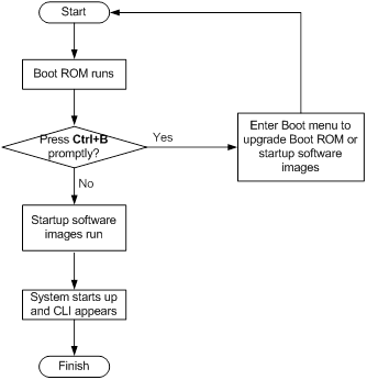
System startup process
Upon power-on, the Boot ROM image runs to initialize hardware and then the software images run to start up the entire system, as shown in Figure 1.
Figure 1 System startup process
Upgrade methods
You can upgrade system software by using one of the following methods:
Upgrading method | Software types | Remarks |
Upgrading from the CLI | · Boot ROM image · Software images | · You must reboot the switch to complete the upgrade. · This method can interrupt ongoing network services. |
Upgrading from the Boot menu | · Boot ROM image · Software images | Use this method when the switch cannot correctly start up.
Upgrading an IRF fabric from the CLI instead of the Boot menu. The Boot menu method increases the service downtime, because it requires that you upgrade the member switches one by one. |
The output in this document is for illustration only and might vary with software releases. This document uses boot.bin and system.bin to represent boot and system image names. The actual software image name format is chassis-model_Comware-version_image-type_release, for example, S5130S_LI-CMW710-BOOT-R6126P39.bin and S5130S_LI-CMW710-SYSM-R6126P39.bin.
Upgrading from the CLI
This section uses a two-member IRF fabric as an example to describe how to upgrade software from the CLI. If you have more than two subordinate switches, repeat the steps for the subordinate switch to upgrade their software. If you are upgrading a standalone switch, ignore the steps for upgrading the subordinate switch. For more information about setting up and configuring an IRF fabric, see the installation guide and IRF configuration guide for the H3C S5130S-LI switch series.
Preparing for the upgrade
Before you upgrade software, complete the following tasks:
1. Log in to the IRF fabric through Telnet or the console port. (Details not shown.)
2. Identify the number of IRF members, each member switch's role, and IRF member ID.
<Sysname> display irf
MemberID Role Priority CPU-Mac Description
*+1 Master 5 0023-8927-afdc ---
2 Standby 1 0023-8927-af43 ---
--------------------------------------------------
* indicates the device is the master.
+ indicates the device through which the user logs in.
The Bridge MAC of the IRF is: 0023-8927-afdb
Auto upgrade : no
Mac persistent : 6 min
Domain ID : 0
3. Verify that each IRF member switch has sufficient storage space for the upgrade images.
| IMPORTANT: Each IRF member switch must have free storage space that is at least two times the size of the upgrade image file. |
# Identify the free flash space of the master switch.
<Sysname> dir
Directory of flash:
0 -rw- 41424 Aug 23 2013 02:23:44 startup.mdb
1 -rw- 3792 Aug 23 2013 02:23:44 startup.cfg
2 -rw- 53555200 Aug 23 2013 09:53:48 system.bin
3 drw- - Aug 23 2013 00:00:07 seclog
4 drw- - Aug 23 2013 00:00:07 diagfile
5 drw- - Aug 23 2013 00:00:07 logfile
6 -rw- 9959424 Aug 23 2013 09:53:48 boot.bin
7 -rw- 9012224 Aug 23 2013 09:53:48 backup.bin
524288 KB total (453416 KB free)
# Identify the free flash space of each subordinate switch, for example, switch 2.
<Sysname> dir slot2#flash:/
Directory of slot2#flash:/
0 -rw- 41424 Jan 01 2011 02:23:44 startup.mdb
1 -rw- 3792 Jan 01 2011 02:23:44 startup.cfg
2 -rw- 93871104 Aug 23 2013 16:00:08 system.bin
3 drw- - Jan 01 2011 00:00:07 seclog
4 drw- - Jan 01 2011 00:00:07 diagfile
5 drw- - Jan 02 2011 00:00:07 logfile
6 -rw- 13611008 Aug 23 2013 15:59:00 boot.bin
7 -rw- 9012224 Nov 25 2011 09:53:48 backup.bin
524288 KB total (453416 KB free)
4. Compare the free flash space of each member switch with the size of the software file to load. If the space is sufficient, start the upgrade process. If not, go to the next step.
5. Delete unused files in the flash memory to free space:
| CAUTION: · To avoid data loss, do not delete the current configuration file. For information about the current configuration file, use the display startup command. · The delete /unreserved file-url command deletes a file permanently and the action cannot be undone. · The delete file-url command moves a file to the recycle bin and the file still occupies storage space. To free the storage space, first execute the undelete command to restore the file, and then execute the delete /unreserved file-url command. |
# Delete unused files from the flash memory of the master switch.
<Sysname> delete /unreserved flash:/backup.bin
The file cannot be restored. Delete flash:/backup.bin?[Y/N]:y
Deleting the file permanently will take a long time. Please wait...
Deleting file flash:/backup.bin...Done.
# Delete unused files from the flash memory of the subordinate switch.
<Sysname> delete /unreserved slot2#flash:/backup.bin
The file cannot be restored. Delete slot2#flash:/backup.bin?[Y/N]:y
Deleting the file permanently will take a long time. Please wait...
Deleting file slot2#flash:/backup.bin...Done.
Downloading software images to the master switch
Before you start upgrading software images packages, make sure you have downloaded the upgrading software files to the root directory in flash memory. This section describes downloading an .ipe software file as an example.
The following are ways to download, upload, or copy files to the master switch:
· FTP download from a server
· FTP upload from a client
· TFTP download from a server
Prerequisites
If FTP or TFTP is used, the IRF fabric and the PC working as the FTP/TFTP server or FTP client can reach each other.
Prepare the FTP server or TFTP server program yourself for the PC. The switch series does not come with these software programs.
FTP download from a server
You can use the switch as an FTP client to download files from an FTP server.
To download a file from an FTP server, for example, the server at 10.10.110.1:
1. Run an FTP server program on the server, configure an FTP username and password, specify the working directory and copy the file, for example, newest.ipe, to the directory.
2. Execute the ftp command in user view on the IRF fabric to access the FTP server.
<Sysname> ftp 10.10.110.1
Trying 10.10.110.1...
Press CTRL+C to abort
Connected to 10.10.110.1(10.10.110.1).
220 FTP service ready.
User (10.10.110.1:(none)):username
331 Password required for username.
Password:
230 User logged in.
3. Enable the binary transfer mode.
ftp> binary
200 Type set to I.
4. Execute the get command in FTP client view to download the file from the FTP server.
ftp> get newest.ipe
227 Entering Passive Mode (10,10,110,1,17,97).
125 BINARY mode data connection already open, transfer starting for /newest.ipe
226 Transfer complete.
32133120 bytes received in 35 seconds (896. 0 kbyte/s)
ftp> bye
221 Server closing.
FTP upload from a client
You can use the IRF fabric as an FTP server and upload files from a client to the IRF fabric.
To FTP upload a file from a client:
On the IRF fabric:
1. Enable FTP server.
<Sysname> system-view
[Sysname] ftp server enable
2. Configure a local FTP user account:
# Create the user account.
[Sysname] local-user abc
# Set its password and specify the FTP service.
[Sysname-luser-manage-abc] password simple pwd
[Sysname-luser-manage-abc] service-type ftp
# Assign the network-admin user role to the user account for uploading file to the working directory of the server.
[Sysname-luser-manage-abc] authorization-attribute user-role network-admin
[Sysname-luser-manage-abc] quit
[Sysname] quit
On the PC:
1. Log in to the IRF fabric (the FTP server) in FTP mode.
c:\> ftp 1.1.1.1
Connected to 1.1.1.1.
220 FTP service ready.
User(1.1.1.1:(none)):abc
331 Password required for abc.
Password:
230 User logged in.
2. Enable the binary file transfer mode.
ftp> binary
200 TYPE is now 8-bit binary.
3. Upload the file (for example, newest.ipe) to the root directory of the flash memory on the master switch.
ftp> put newest.ipe
200 PORT command successful
150 Connecting to port 10002
226 File successfully transferred
ftp: 32133120 bytes sent in 64.58 secs (497.60 Kbytes/sec).
TFTP download from a server
To download a file from a TFTP server, for example, the server at 10.10.110.1:
1. Run a TFTP server program on the server, specify the working directory, and copy the file, for example, newest.ipe, to the directory.
2. On the IRF fabric, execute the tftp command in user view to download the file to the root directory of the flash memory on the master switch.
<Sysname> tftp 10.10.110.1 get newest.ipe
Press CTRL+C to abort.
% Total % Received % Xferd Average Speed Time Time Time Current
Dload Upload Total Spent Left Speed
100 30.6M 0 30.6M 0 0 143k 0 --:--:-- 0:03:38 --:--:-- 142k
Upgrading the software images
To upgrade the software images:
1. Specify the upgrade image file (newest.ipe in this example) used at the next startup for the master switch, and assign the M attribute to the boot and system images in the file.
<Sysname> boot-loader file flash:/newest.ipe slot 1 main
Verifying image file..........Done.
Images in IPE:
boot.bin
system.bin
This command will set the main startup software images. Continue? [Y/N]:y
Add images to target slot.
Decompressing file boot.bin to flash:/boot.bin....................Done.
Decompressing file system.bin to flash:/system.bin................Done.
The images that have passed all examinations will be used as the main startup so
ftware images at the next reboot on slot 1.
2. Specify the upgrade image file as the main startup image file for each subordinate switch. This example uses IRF member 2. (The subordinate switches will automatically copy the file to the root directory of their flash memories.)
<Sysname> boot-loader file flash:/newest.ipe slot 2 main
Verifying image file..........Done.
Images in IPE:
boot.bin
system.bin
This command will set the main startup software images. Continue? [Y/N]:y
Add images to target slot.
Decompressing file boot.bin to flash:/boot.bin....................Done.
Decompressing file system.bin to flash:/system.bin................Done.
The images that have passed all examinations will be used as the main startup so
ftware images at the next reboot on slot 2.
3. Enable the software auto-update function.
<Sysname> system-view
[Sysname] irf auto-update enable
[Sysname] quit
This function checks the software versions of member switches for inconsistency with the master switch. If a subordinate switch is using a different software version than the master, the function propagates the current software images of the master to the subordinate as main startup images. The function prevents software version inconsistency from causing the IRF setup failure.
4. Save the current configuration in any view to prevent data loss.
<Sysname> save
The current configuration will be written to the device. Are you sure? [Y/N]:y
Please input the file name(*.cfg)[flash:/startup.cfg]
(To leave the existing filename unchanged, press the enter key):
flash:/startup.cfg exists, overwrite? [Y/N]:y
Validating file. Please wait.................
Saved the current configuration to mainboard device successfully.
Slot 2:
Save next configuration file successfully.
5. Reboot the IRF fabric to complete the upgrade.
<Sysname> reboot
Start to check configuration with next startup configuration file, please wait.
........DONE!
This command will reboot the device. Continue? [Y/N]:y
Now rebooting, please wait...
The system automatically loads the .bin boot and system images in the .ipe file and sets them as the startup software images.
6. Execute the display version command in any view to verify that the current main software images have been updated (details not shown).
| NOTE: The system automatically checks the compatibility of the Boot ROM image and the boot and system images during the reboot. If you are prompted that the Boot ROM image in the upgrade image file is different than the current Boot ROM image, upgrade both the basic and extended sections of the Boot ROM image for compatibility. If you choose to not upgrade the Boot ROM image, the system will ask for an upgrade at the next reboot performed by powering on the switch or rebooting from the CLI (promptly or as scheduled). If you fail to make any choice in the required time, the system upgrades the entire Boot ROM image. |
Upgrading from the Boot menu
In this approach, you must access the Boot menu of each member switch to upgrade their software one by one. If you are upgrading software images for an IRF fabric, using the CLI is a better choice.
| TIP: Upgrading through the Ethernet port is faster than through the console port. |
Prerequisites
Make sure the prerequisites are met before you start upgrading software from the Boot menu.
Setting up the upgrade environment
1. Use a console cable to connect the console terminal (for example, a PC) to the console port on the switch.
2. Connect the Ethernet port on the switch to the file server.
| NOTE: The file server and the configuration terminal can be co-located. |
3. Run a terminal emulator program on the console terminal and set the following terminal settings:
¡ Bits per second—9,600
¡ Data bits—8
¡ Parity—None
¡ Stop bits—1
¡ Flow control—None
¡ Emulation—VT100
Preparing for the TFTP or FTP transfer
To use TFTP or FTP:
· Run a TFTP or FTP server program on the file server or the console terminal.
· Copy the upgrade file to the file server.
· Correctly set the working directory on the TFTP or FTP server.
· Make sure the file server and the switch can reach each other.
Verifying that sufficient storage space is available
| IMPORTANT: For the switch to start up correctly, do not delete the main startup software images when you free storage space before upgrading Boot ROM. On the Boot menu, the main startup software images are marked with an asterisk (*). |
When you upgrade software, make sure each member switch has sufficient free storage space for the upgrade file, as shown in Table 6.
Table 6 Minimum free storage space requirements
Upgraded images | Minimum free storage space requirements |
Comware images | Two times the size of the Comware upgrade package file. |
Boot ROM | Same size as the Boot ROM upgrade image file. |
If no sufficient space is available, delete unused files as described in “Managing files from the Boot menu.”
Scheduling the upgrade time
During the upgrade, the switch cannot provide any services. You must make sure the upgrade has a minimal impact on the network services.
Accessing the Boot menu
Starting......
Press Ctrl+D to access BASIC BOOT MENU
Booting Normal Extend BootWare....
********************************************************************************
* *
* H3C S5130S-28S-LI Switch BOOTROM, Version 126 *
* *
********************************************************************************
Copyright (c) 2004-2019 New H3C Technologies Co., Ltd.
Creation Date : Feb 10 2017, 17:21:39
CPU Clock Speed : 800MHz
Memory Size : 512MB
Flash Size : 256MB
CPLD Version : 001
PCB Version : Ver.A
Mac Address : aa1122334455
Press Ctrl+B to access EXTENDED BOOT MENU...1
Press one of the shortcut key combinations at prompt.
Shortcut keys | Prompt message | Function | Remarks |
Ctrl+B | Press Ctrl+B to enter Extended Boot menu... | Accesses the extended Boot menu. | Press the keys within 1 second (in fast startup mode) or 5 seconds (in full startup mode) after the message appears. You can upgrade and manage system software and Boot ROM from this menu. |
Accessing the extended Boot menu
Press Ctrl+B within 1 second (in fast startup mode) or 5 seconds (in full startup mode) after the "Press Ctrl-B to enter Extended Boot menu..." prompt message appears. If you fail to do this, the system starts decompressing the system software.
Alternatively, you can enter 4 in the basic Boot menu to access the extended Boot menu.
The "Password recovery capability is enabled." or "Password recovery capability is disabled." message appears, followed by the extended Boot menu. Availability of some menu options depends on the state of password recovery capability (see Table 8). For more information about password recovery capability, see Fundamentals Configuration Guide in H3C S5130S-LI Switch Series Configuration Guides.
Password recovery capability is enabled.
EXTENDED BOOT MENU
1. Download image to flash
2. Select image to boot
3. Display all files in flash
4. Delete file from flash
5. Restore to factory default configuration
6. Enter BootRom upgrade menu
7. Skip current system configuration
8. Set switch startup mode
0. Reboot
Ctrl+Z: Access EXTENDED ASSISTANT MENU
Ctrl+F: Format file system
Ctrl+P: Change authentication for console login
Ctrl+R: Download image to SDRAM and run
Ctrl+Y: Change Work Mode
Ctrl+C: Display Copyright
Enter your choice(0-8):
Table 8 Extended Boot ROM menu options
Option | Tasks |
1. Download image to flash | Download a software image file to the flash. |
2. Select image to boot | · Specify the main and backup software image file for the next startup. · Specify the main and backup configuration files for the next startup. This task can be performed only if password recovery capability is enabled. |
3. Display all files in flash | Display files on the flash. |
4. Delete file from flash | Delete files to free storage space. |
5. Restore to factory default configuration | Delete the current next-startup configuration files and restore the factory-default configuration. This option is available only if password recovery capability is disabled. |
6. Enter BootRom upgrade menu | Access the Boot ROM upgrade menu. |
7. Skip current system configuration | Start the switch without loading any configuration file. This is a one-time operation and takes effect only for the first system boot or reboot after you choose this option. This option is available only if password recovery capability is enabled. |
8. Set switch startup mode | Set the startup mode to fast startup mode or full startup mode. |
0. Reboot | Reboot the switch. |
Ctrl+F: Format file system | Format the current storage medium. |
Ctrl+P: Change authentication for console login | Skip the authentication for console login. This is a one-time operation and takes effect only for the first system boot or reboot after you choose this option. This option is available only if password recovery capability is enabled. |
Ctrl+R: Download image to SDRAM and run | Download a system software image and start the switch with the image. This option is available only if password recovery capability is enabled. |
Ctrl+Z: Access EXTENDED ASSISTANT MENU | Access the EXTENDED ASSISTANT MENU. For options in the menu, see Table 9. |
Ctrl+Y: Change Work Mode | Change Work Mode. |
Ctrl+C: Display Copyright | Display the copyright statement. |
Table 9 EXTENDED ASSISTANT menu options
Option | Task |
1. Display Memory | Display data in the memory. |
2. Search Memory | Search the memory for a specific data segment. |
0. Return to boot menu | Return to the extended Boot ROM menu. |
Upgrading Comware images from the Boot menu
You can use the following methods to upgrade Comware images:
· Using TFTP to upgrade software images through the Ethernet port
· Using FTP to upgrade software images through the Ethernet port
· Using XMODEM to upgrade software through the console port
Using TFTP to upgrade software images through the Ethernet port
1. Enter 1 in the Boot menu to access the file transfer protocol submenu.
1. Set TFTP protocol parameters
2. Set FTP protocol parameters
3. Set XMODEM protocol parameters
0. Return to boot menu
Enter your choice(0-3):
2. Enter 1 to set the TFTP parameters.
Load File Name :update.ipe
Server IP Address :192.168.0.3
Local IP Address :192.168.0.2
Subnet Mask :255.255.255.0
Gateway IP Address :0.0.0.0
Table 10 TFTP parameter description
Item | Description |
Load File Name | Name of the file to download (for example, update.ipe). |
Server IP Address | IP address of the TFTP server (for example, 192.168.0.3). |
Local IP Address | IP address of the switch (for example, 192.168.0.2). |
Subnet Mask | Subnet mask of the switch (for example, 255.255.255.0). |
Gateway IP Address | IP address of the gateway (in this example, no gateway is required because the server and the switch are on the same subnet). |
| NOTE: · To use the default setting for a field, press Enter without entering any value. · If the switch and the server are on different subnets, you must specify a gateway address for the switch. |
3. Enter all required parameters, and enter Y to confirm the settings. The following prompt appears:
Are you sure to download file to flash? Yes or No (Y/N):Y
4. Enter Y to start downloading the image file. To return to the Boot menu without downloading the upgrade file, enter N.
Loading.........................................................................
................................................................................
................................................................................
................................................................Done!
5. Enter the M (main), B (backup), or N (none) attribute for the images. In this example, assign the main attribute to the images.
Please input the file attribute (Main/Backup/None) M
Image file boot.bin is self-decompressing...
Free space: 534980608 bytes
Writing flash...................................................................
................................................................................
...................................................................Done!
Image file system.bin is self-decompressing...
Free space: 525981696 bytes
Writing flash...................................................................
................................................................................
................................................................................
................................................................................
................................................................................
................................................................................
.......................................................................Done!
| NOTE: · The switch always attempts to boot with the main images first. If the attempt fails, for example, because the main images are not available, the switch tries to boot with the backup images. An image with the none attribute is only stored in flash memory for backup. To use it at reboot, you must change its attribute to main or backup. · If an image with the same attribute as the image you are loading is already in the flash memory, the attribute of the old image changes to none after the new image becomes valid. |
6. Enter 0 in the Boot menu to reboot the switch with the new software images.
EXTENDED BOOT MENU
1. Download image to flash
2. Select image to boot
3. Display all files in flash
4. Delete file from flash
5. Restore to factory default configuration
6. Enter BootRom upgrade menu
7. Skip current system configuration
8. Set switch startup mode
0. Reboot
Ctrl+Z: Access EXTENDED ASSISTANT MENU
Ctrl+F: Format file system
Ctrl+P: Change authentication for console login
Ctrl+R: Download image to SDRAM and run
Ctrl+Y: Change Work Mode
Ctrl+C: Display Copyright
Enter your choice(0-8): 0
Using FTP to upgrade software images through the Ethernet port
1. Enter 1 in the Boot menu to access the file transfer protocol submenu.
1. Set TFTP protocol parameters
2. Set FTP protocol parameters
3. Set XMODEM protocol parameters
0. Return to boot menu
Enter your choice(0-3):
2. Enter 2 to set the FTP parameters.
Load File Name :update.ipe
Server IP Address :192.168.0.3
Local IP Address :192.168.0.2
Subnet Mask :255.255.255.0
Gateway IP Address :0.0.0.0
FTP User Name :switch
FTP User Password :***
Table 11 FTP parameter description
Item | Description |
Load File Name | Name of the file to download (for example, update.ipe). |
Server IP Address | IP address of the FTP server (for example, 192.168.0.3). |
Local IP Address | IP address of the switch (for example, 192.168.0.2). |
Subnet Mask | Subnet mask of the switch (for example, 255.255.255.0). |
Gateway IP Address | IP address of the gateway (in this example, no gateway is required because the server and the switch are on the same subnet). |
FTP User Name | Username for accessing the FTP server, which must be the same as configured on the FTP server. |
FTP User Password | Password for accessing the FTP server, which must be the same as configured on the FTP server. |
| NOTE: · To use the default setting for a field, press Enter without entering any value. · If the switch and the server are on different subnets, you must specify a gateway address for the switch. |
3. Enter all required parameters, and enter Y to confirm the settings. The following prompt appears:
Are you sure to download file to flash? Yes or No (Y/N):Y
4. Enter Y to start downloading the image file. To return to the Boot menu without downloading the upgrade file, enter N.
Loading.........................................................................
................................................................................
................................................................................
................................................................Done!
5. Enter the M (main), B (backup), or N (none) attribute for the images. In this example, assign the main attribute to the images.
Please input the file attribute (Main/Backup/None) M
Image file boot.bin is self-decompressing...
Free space: 534980608 bytes
Writing flash...................................................................
................................................................................
...................................................................Done!
Image file system.bin is self-decompressing...
Free space: 525981696 bytes
Writing flash...................................................................
................................................................................
................................................................................
................................................................................
................................................................................
................................................................................
.......................................................................Done!
EXTENDED BOOT MENU
1. Download image to flash
2. Select image to boot
3. Display all files in flash
4. Delete file from flash
5. Restore to factory default configuration
6. Enter BootRom upgrade menu
7. Skip current system configuration
8. Set switch startup mode
0. Reboot
Ctrl+Z: Access EXTENDED ASSISTANT MENU
Ctrl+F: Format file system
Ctrl+P: Change authentication for console login
Ctrl+R: Download image to SDRAM and run
Ctrl+Y: Change Work Mode
Ctrl+C: Display Copyright
Enter your choice(0-8):0
| NOTE: · The switch always attempts to boot with the main images first. If the attempt fails, for example, because the main images not available, the switch tries to boot with the backup images. An image with the none attribute is only stored in flash memory for backup. To use it at reboot, you must change its attribute to main or backup. · If an image with the same attribute as the image you are loading is already in the flash memory, the attribute of the old image changes to none after the new image becomes valid. |
6. Enter 0 in the Boot menu to reboot the switch with the new software images.
Using XMODEM to upgrade software through the console port
XMODEM download through the console port is slower than TFTP or FTP download through the Ethernet port. To save time, use the Ethernet port as long as possible.
1. Enter 1 in the Boot menu to access the file transfer protocol submenu.
1. Set TFTP protocol parameters
2. Set FTP protocol parameters
3. Set XMODEM protocol parameters
0. Return to boot menu
Enter your choice(0-3):
2. Enter 3 to set the XMODEM download baud rate.
Please select your download baudrate:
1.* 9600
2. 19200
3. 38400
4. 57600
5. 115200
0. Return to boot menu
Enter your choice(0-5):5
3. Select an appropriate download rate, for example, enter 5 to select 115200 bps.
Download baudrate is 115200 bps
Please change the terminal's baudrate to 115200 bps and select XMODEM protocol
Press enter key when ready
4. Set the serial port on the terminal to use the same baud rate and protocol as the console port. If you select 9600 bps as the download rate for the console port, skip this task.
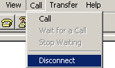
a. Select Call > Disconnect in the HyperTerminal window to disconnect the terminal from the switch.
Figure 2 Disconnecting the terminal from the switch
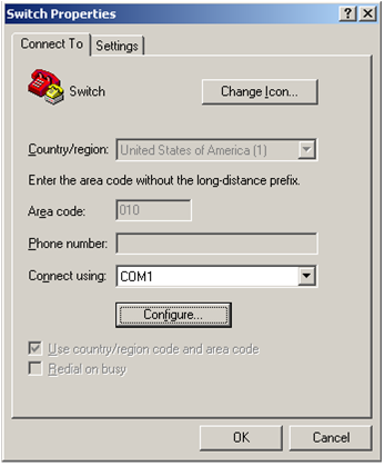
b. Select File > Properties, and in the Properties dialog box, click Configure.
Figure 3 Properties dialog box
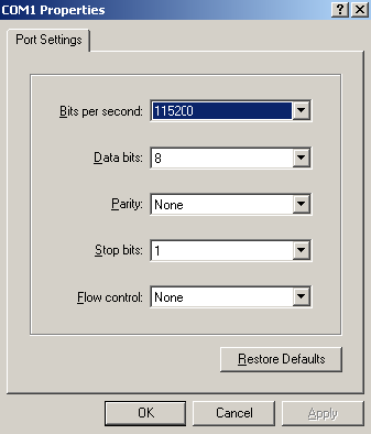
c. Select 115200 from the Bits per second list and click OK.
Figure 4 Modifying the baud rate
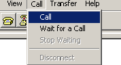
d. Select Call > Call to reestablish the connection.
Figure 5 Reestablishing the connection
5. Press Enter. The following prompt appears:
Are you sure to download file to flash? Yes or No (Y/N):Y
6. Enter Y to start downloading the file. (To return to the Boot menu, enter N.)
Now please start transfer file with XMODEM protocol
If you want to exit, Press <Ctrl+X>
Loading ...CCCCCCCCCCCCCCCCCCCCCCCCC
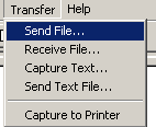
7. Select Transfer > Send File in the HyperTerminal window.
Figure 6 Transfer menu
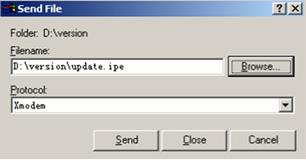
8. In the dialog box that appears, click Browse to select the source file, and select Xmodem from the Protocol list.
Figure 7 File transmission dialog box
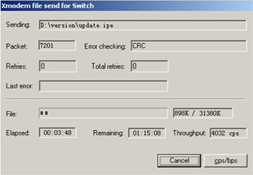
9. Click Send. The following dialog box appears:
Figure 8 File transfer progress
10. Enter the M (main), B (backup), or N (none) attribute for the images. In this example, assign the main attribute to the images.
Please input the file attribute (Main/Backup/None) m
The boot.bin image is self-decompressing...
# At the Load File name prompt, enter a name for the boot image to be saved to flash memory.
Load File name : default_file boot-update.bin (At the prompt,
Free space: 470519808 bytes
Writing flash...................................................................
.............Done!
The system-update.bin image is self-decompressing...
# At the Load File name prompt, enter a name for the system image to be saved to flash memory.
Load File name : default_file system-update.bin
Free space: 461522944 bytes
Writing flash...................................................................
.............Done!
Your baudrate should be set to 9600 bps again!
Press enter key when ready
| NOTE: · The switch always attempts to boot with the main images first. If the attempt fails, for example, because the main images not available, the switch tries to boot with the backup images. An image with the none attribute is only stored in the flash memory for backup. To use it at reboot, you must change its attribute to main or backup. · If an image with the same attribute as the image you are loading is already in flash memory, the attribute of the old image changes to none after the new image becomes valid. |
11. If the baud rate of the HyperTerminal is not 9600 bps, restore it to 9600 bps as described in step 5.a. If the baud rate is 9600 bps, skip this step.
| NOTE: The console port rate reverts to 9600 bps at a reboot. If you have changed the baud rate, you must perform this step so you can access the switch through the console port after a reboot. |
EXTENDED BOOT MENU
1. Download image to flash
2. Select image to boot
3. Display all files in flash
4. Delete file from flash
5. Restore to factory default configuration
6. Enter BootRom upgrade menu
7. Skip current system configuration
8. Set switch startup mode
0. Reboot
Ctrl+Z: Access EXTENDED ASSISTANT MENU
Ctrl+F: Format file system
Ctrl+P: Change authentication for console login
Ctrl+R: Download image to SDRAM and run
Ctrl+Y: Change Work Mode
Ctrl+C: Display Copyright
Enter your choice(0-8): 0
12. Enter 0 in the Boot menu to reboot the system with the new software images.
Upgrading Boot ROM from the Boot menu
You can use the following methods to upgrade the Boot ROM image:
· Using TFTP to upgrade Boot ROM through the Ethernet port
· Using FTP to upgrade Boot ROM through the Ethernet port
· Using XMODEM to upgrade Boot ROM through the console port
Using TFTP to upgrade Boot ROM through the Ethernet port
1. Enter 6 in the Boot menu to access the Boot ROM update menu.
1. Update full BootRom
2. Update extended BootRom
3. Update basic BootRom
0. Return to boot menu
Enter your choice(0-3):
2. Enter 1 in the Boot ROM update menu to upgrade the full Boot ROM.
The file transfer protocol submenu appears:
1. Set TFTP protocol parameters
2. Set FTP protocol parameters
3. Set XMODEM protocol parameters
0. Return to boot menu
Enter your choice(0-3):
3. Enter 1 to set the TFTP parameters.
Load File Name :update.btm
Server IP Address :192.168.0.3
Local IP Address :192.168.0.2
Subnet Mask :255.255.255.0
Gateway IP Address :0.0.0.0
Table 12 TFTP parameter description
Item | Description |
Load File Name | Name of the file to download (for example, update.btm). |
Server IP Address | IP address of the TFTP server (for example, 192.168.0.3). |
Local IP Address | IP address of the switch (for example, 192.168.0.2). |
Subnet Mask | Subnet mask of the switch (for example, 255.255.255.0). |
Gateway IP Address | IP address of the gateway (in this example, no gateway is required because the server and the switch are on the same subnet). |
| NOTE: · To use the default setting for a field, press Enter without entering any value. · If the switch and the server are on different subnets, you must specify a gateway address for the switch. |
4. Enter all required parameters and press Enter to start downloading the file.
Loading.................................................Done!
5. Enter Y at the prompt to upgrade the basic Boot ROM section.
Will you Update Basic BootRom? (Y/N):Y
Updating Basic BootRom...........Done.
6. Enter Y at the prompt to upgrade the extended Boot ROM section.
Updating extended BootRom? (Y/N):Y
Updating extended BootRom.........Done.
7. Enter 0 in the Boot ROM update menu to return to the Boot menu.
1. Update full BootRom
2. Update extended BootRom
3. Update basic BootRom
0. Return to boot menu
Enter your choice(0-3):
8. Enter 0 in the Boot menu to reboot the switch with the new Boot ROM image.
Using FTP to upgrade Boot ROM through the Ethernet port
1. Enter 6 in the Boot menu to access the Boot ROM update menu.
1. Update full BootRom
2. Update extended BootRom
3. Update basic BootRom
0. Return to boot menu
Enter your choice(0-3):
2. Enter 1 in the Boot ROM update menu to upgrade the full Boot ROM.
The file transfer protocol submenu appears:
1. Set TFTP protocol parameters
2. Set FTP protocol parameters
3. Set XMODEM protocol parameters
0. Return to boot menu
Enter your choice(0-3):
3. Enter 2 to set the FTP parameters.
Load File Name :update.btm
Server IP Address :192.168.0.3
Local IP Address :192.168.0.2
Subnet Mask :255.255.255.0
Gateway IP Address :0.0.0.0
FTP User Name :switch
FTP User Password :123
Table 13 FTP parameter description
Item | Description |
Load File Name | Name of the file to download (for example, update.btm). |
Server IP Address | IP address of the FTP server (for example, 192.168.0.3). |
Local IP Address | IP address of the switch (for example, 192.168.0.2). |
Subnet Mask | Subnet mask of the switch (for example, 255.255.255.0). |
Gateway IP Address | IP address of the gateway (in this example, no gateway is required because the server and the switch are on the same subnet). |
FTP User Name | Username for accessing the FTP server, which must be the same as configured on the FTP server. |
FTP User Password | Password for accessing the FTP server, which must be the same as configured on the FTP server. |
| NOTE: · To use the default setting for a field, press Enter without entering any value. · If the switch and the server are on different subnets, you must specify a gateway address for the switch. |
4. Enter all required parameters and press Enter to start downloading the file.
Loading.................................................Done!
5. Enter Y at the prompt to upgrade the basic Boot ROM section.
Will you Update Basic BootRom? (Y/N):Y
Updating Basic BootRom...........Done.
6. Enter Y at the prompt to upgrade the extended Boot ROM section.
Updating extended BootRom? (Y/N):Y
Updating extended BootRom.........Done.
7. Enter 0 in the Boot ROM update menu to return to the Boot menu.
1. Update full BootRom
2. Update extended BootRom
3. Update basic BootRom
0. Return to boot menu
Enter your choice(0-3):
8. Enter 0 in the Boot menu to reboot the switch with the new Boot ROM image.
Using XMODEM to upgrade Boot ROM through the console port
XMODEM download through the console port is slower than TFTP or FTP download through the Ethernet port. To save time, use the Ethernet port as long as possible.
1. Enter 6 in the Boot menu to access the Boot ROM update menu.
1. Update full BootRom
2. Update extended BootRom
3. Update basic BootRom
0. Return to boot menu
Enter your choice(0-3):
2. Enter 1 in the Boot ROM update menu to upgrade the full Boot ROM.
The file transfer protocol submenu appears:
1. Set TFTP protocol parameters
2. Set FTP protocol parameters
3. Set XMODEM protocol parameters
0. Return to boot menu
Enter your choice(0-3):
3. Enter 3 to set the XMODEM download baud rate.
Please select your download baudrate:
1.* 9600
2. 19200
3. 38400
4. 57600
5. 115200
0. Return to boot menu
Enter your choice(0-5):5
4. Select an appropriate download rate, for example, enter 5 to select 115200 bps.
Download baudrate is 115200 bps
Please change the terminal's baudrate to 115200 bps and select XMODEM protocol
Press enter key when ready
5. Set the serial port on the terminal to use the same baud rate and protocol as the console port. If you select 9600 bps as the download rate for the console port, skip this task.
a. Select Call > Disconnect in the HyperTerminal window to disconnect the terminal from the switch.
Figure 9 Disconnecting the terminal from the switch
b. Select File > Properties, and in the Properties dialog box, click Configure.
Figure 10 Properties dialog box

c. Select 115200 from the Bits per second list and click OK.
Figure 11 Modifying the baud rate
d. Select Call > Call to reestablish the connection.
Figure 12 Reestablishing the connection
6. Press Enter to start downloading the file.
Now please start transfer file with XMODEM protocol
If you want to exit, Press <Ctrl+X>
Loading ...CCCCCCCCCCCCCCCCCCCCCCCCC
7. Select Transfer > Send File in the HyperTerminal window.
Figure 13 Transfer menu
8. In the dialog box that appears, click Browse to select the source file, and select Xmodem from the Protocol list.
Figure 14 File transmission dialog box
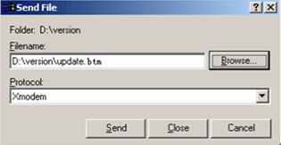
9. Click Send. The following dialog box appears:
Figure 15 File transfer progress
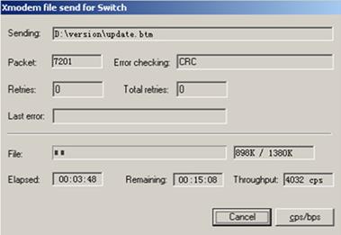
10. Enter Y at the prompt to upgrade the basic Boot ROM section.
Loading ...CCCCCCCCCCCCCC ...Done!
Will you Update Basic BootRom? (Y/N):Y
Updating Basic BootRom...........Done.
11. Enter Y at the prompt to upgrade the extended Boot ROM section.
Updating extended BootRom? (Y/N):Y
Updating extended BootRom.........Done.
12. If the baud rate of the HyperTerminal is not 9600 bps, restore it to 9600 bps at the prompt, as described in step 4.a. If the baud rate is 9600 bps, skip this step.
Please change the terminal's baudrate to 9600 bps, press ENTER when ready.
| NOTE: The console port rate reverts to 9600 bps at a reboot. If you have changed the baud rate, you must perform this step so you can access the switch through the console port after a reboot. |
13. Press Enter to access the Boot ROM update menu.
14. Enter 0 in the Boot ROM update menu to return to the Boot menu.
1. Update full BootRom
2. Update extended BootRom
3. Update basic BootRom
0. Return to boot menu
Enter your choice(0-3):
15. Enter 0 in the Boot menu to reboot the switch with the new Boot ROM image.
Managing files from the Boot menu
From the Boot menu, you can display files in flash memory to check for obsolete files, incorrect files, or space insufficiency, delete files to release storage space, or change the attributes of software images.
Displaying all files
Enter 3 in the Boot menu to display all files in flash memory and identify the free space size.
EXTENDED BOOT MENU
1. Download image to flash
2. Select image to boot
3. Display all files in flash
4. Delete file from flash
5. Restore to factory default configuration
6. Enter BootRom upgrade menu
7. Skip current system configuration
8. Set switch startup mode
0. Reboot
Ctrl+Z: Access EXTENDED ASSISTANT MENU
Ctrl+F: Format file system
Ctrl+P: Change authentication for console login
Ctrl+R: Download image to SDRAM and run
Ctrl+Y: Change Work Mode
Ctrl+C: Display Copyright
Enter your choice(0-8): 3
The following is a sample output:
Display all file(s) in flash:
File Number File Size(bytes) File Name
================================================================================
1 8177 flash:/testbackup.cfg
2(*) 53555200 flash:/system.bin
3(*) 9959424 flash:/boot.bin
4 3678 flash:/startup.cfg_backup
5 30033 flash:/default.mdb
6 42424 flash:/startup.mdb
7 18 flash:/.pathfile
8 232311 flash:/logfile/logfile.log
9 5981 flash:/startup.cfg_back
10(*) 6098 flash:/startup.cfg
11 20 flash:/.snmpboots
Free space: 464298848 bytes
The current image is boot.bin
(*)-with main attribute
(b)-with backup attribute
(*b)-with both main and backup attribute
Deleting files
If storage space is insufficient, delete obsolete files to free up storage space.
To delete files:
1. Enter 4 in the Boot menu:
Deleting the file in flash:
File Number File Size(bytes) File Name
================================================================================
1 8177 flash:/testbackup.cfg
2(*) 53555200 flash:/system.bin
3(*) 9959424 flash:/boot.bin
4 3678 flash:/startup.cfg_backup
5 30033 flash:/default.mdb
6 42424 flash:/startup.mdb
7 18 flash:/.pathfile
8 232311 flash:/logfile/logfile.log
9 5981 flash:/startup.cfg_back
10(*) 6098 flash:/startup.cfg
11 20 flash:/.snmpboots
Free space: 464298848 bytes
The current image is boot.bin
(*)-with main attribute
(b)-with backup attribute
(*b)-with both main and backup attribute
2. Enter the number of the file to delete. For example, enter 1 to select the file testbackup.cfg.
Please input the file number to change: 1
3. Enter Y at the confirmation prompt.
The file you selected is testbackup.cfg,Delete it? (Y/N):Y
Deleting....................................Done!
Changing the attribute of software images
Software image attributes include main (M), backup (B), and none (N). System software and boot software can each have multiple none-attribute images but only one main image and one backup image on the switch. You can assign both the M and B attributes to one image. If the M or B attribute you are assigning has been assigned to another image, the assignment removes the attribute from that image. If the removed attribute is the sole attribute of the image, its attribute changes to N.
For example, the system image system.bin has the M attribute and the system image system-update.bin has the B attribute. After you assign the M attribute to system-update.bin, the attribute of system-update.bin changes to M+B and the attribute of system.bin changes to N.
To change the attribute of a system or boot image:
1. Enter 2 in the Boot menu.
EXTENDED BOOT MENU
1. Download image to flash
2. Select image to boot
3. Display all files in flash
4. Delete file from flash
5. Restore to factory default configuration
6. Enter BootRom upgrade menu
7. Skip current system configuration
8. Set switch startup mode
0. Reboot
Ctrl+Z: Access EXTENDED ASSISTANT MENU
Ctrl+F: Format file system
Ctrl+P: Change authentication for console login
Ctrl+R: Download image to SDRAM and run
Ctrl+Y: Change Work Mode
Ctrl+C: Display Copyright
Enter your choice(0-8): 2
2. 1 or 2 at the prompt to set the attribute of a software image. (The following output is based on the option 2. To set the attribute of a configuration file, enter 3.)
1. Set image file
2. Set bin file
3. Set configuration file
0. Return to boot menu
Enter your choice(0-3): 2
File Number File Size(bytes) File Name
================================================================================
1(*) 53555200 flash:/system.bin
2(*) 9959424 flash:/boot.bin
3 13105152 flash:/boot-update.bin
4 91273216 flash:/system-update.bin
Free space: 417177920 bytes
(*)-with main attribute
(b)-with backup attribute
(*b)-with both main and backup attribute
Note:Select .bin files. One but only one boot image and system image must be included.
3. Enter the number of the file you are working with. For example, enter 3 to select the boot image boot-update.bin. and enter 4 to select the system image system-update.bin.
Enter file No.(Allows multiple selection):3
Enter another file No.(0-Finish choice):4
4. Enter 0 to finish the selection.
Enter another file No.(0-Finish choice):0
You have selected:
flash:/boot-update.bin
flash:/system-update.bin
5. Enter M or B to change its attribute to main or backup. If you change its attribute to M, the attribute of boot.bin changes to none.
Please input the file attribute (Main/Backup) M
This operation may take several minutes. Please wait....
Next time, boot-update.bin will become default boot file!
Next time, system-update.bin will become default boot file!
Set the file attribute success!
Handling software upgrade failures
If a software upgrade fails, the system runs the old software version.
To handle a software upgrade failure:
1. Verify that the software release is compatible with the switch model and the correct file is used.
2. Verify that the software release and the Boot ROM release are compatible. For software and Boot ROM compatibility, see the hardware and software compatibility matrix in the correct release notes.
3. Check the physical ports for a loose or incorrect connection.
4. If you are using the console port for file transfer, check the HyperTerminal settings (including the baud rate and data bits) for any wrong setting.
5. Check the file transfer settings:
¡ If XMODEM is used, you must set the same baud rate for the terminal as for the console port.
¡ If TFTP is used, you must enter the same server IP addresses, file name, and working directory as set on the TFTP server.
¡ If FTP is used, you must enter the same FTP server IP address, source file name, working directory, and FTP username and password as set on the FTP server.
6. Check the FTP or TFTP server for any incorrect setting.
7. Check that the storage device has sufficient space for the upgrade file.