| Title | Size | Downloads |
|---|---|---|
| H3C S5800-60C-PWR_S5820X-28C Series LSWM1WCM10 Card Manual-5PW100-book.pdf | 576.83 KB |
- Table of Contents
Access Controller Module LSWM1WCM10
1 Overview
The H3C LSWM1WCM10 access controller module is a wireless access controller (AC) product developed by Hangzhou H3C Technologies Co., Ltd. (referred to as H3C hereinafter). The LSWM1WCM10 is applicable to the H3C S5800-60C-PWR and S5820X-28C series Ethernet switches and can address the deployment requirements of large- and medium-sized WLAN networks. It features large capacity, high reliability and rich services and provides powerful WLAN access control capability. Designed for WLAN access of enterprise networks, the LSWM1WCM10 provides the most ideal access control solutions for WLAN access of large- and medium-sized enterprise campus networks, wireless area coverage and hot spot coverage.
2 Hardware Features of the LSWM1WCM10
(1) Appearance
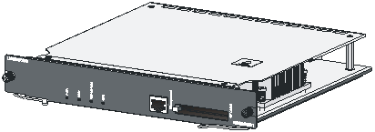
The silkscreen LSWM1WCM10 is printed at the upper left corner of the front panel, which is used to identify the module. The following figure depicts the appearance of the module.
Figure-1 Appearance of the LSWM1WCM10
(2) Specifications
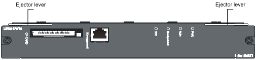
The LSWM1WCM10 can provide wireless features for the S5800-60C-PWR and S5820X-28C series switches. It provides one 10/100/1000Base-TX interface for out-of-band management. The following figure depicts the front panel of the LSWM1WCM10.
Figure-2 Front panel of the LSWM1WCM10
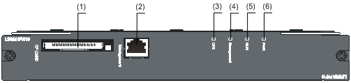
(1) CF card slot | (2) Management Ethernet interface |
(3) CF card status LED (CFS) | (4) Management Ethernet interface status LED (Management) |
(5) System status LED (RUN) | (6) PWR LED |
(3) Description of the LEDs on the front panel
The LSWM1WCM10 provides four LEDs PWR, RUN, CFS and Management. See Table1 for the description.
Table1 Description of the LEDs on the front panel
LED | Color | Status | Description |
PWR | Green/Red | Steady green | The power system operates normally. |
Steady red | The power system fails. | ||
Off | No power supply to the LSWM1WCM10. Note that: If you install the LSWM1WCM10 to a switch working normally but the PWR LED is off, check whether the LSWM1WCM10 is well connected. | ||
RUN | Green | Flashing green (1.5 Hz) | The system operates normally. |
Flashing green (6 Hz) | The system is booting/loading software. | ||
Off | The system operates abnormally or the system is reset. Note that: When the system is reset, the RUN LED is off; when the system is starting up, the RUN LED fast blinks; when the system completes startup and works normally, the RUN LED blinks slowly. | ||
CFS | Green | Steady green | The CF card operates normally, and no write or read operation is being performed. |
Flashing green | The CF card operates normally, and a write or read operation is being performed. | ||
Off | The CF card is not in position. | ||
Management | Green/Yellow | Steady green | The port operates at a rate of 1000 Mbps; no data is being sent and/or received on the port. |
Flashing green | The port operates at a rate of 1000 Mbps and is sending and/or receiving data. | ||
Steady yellow | The port operates at a rate of 10/100 Mbps; no data is being sent and/or received on the port. | ||
Flashing yellow | The port operates at a rate of 10/100 Mbps and is sending and/or receiving data. | ||
Off | No connection is available on the port. |
Table2 LSWM1WCM10 specifications
Item | Specification |
CPU frequency | 1 GHz |
CF card | l Provides one CF card slot and one 1 GB CF card when shipped. l Supports a CF card with a maximum capacity of 1 GB. |
Capacity | 2 GB |
Dimensions (H × W × D) | 35 × 250 × 243 mm (1.38 × 9.84 × 9.57 in.) |
Power consumption | 36.5 W to 80 W |
Weight | 1.65 kg (3.64 lb) |
Interface | One 10/100/1000Base-TX Ethernet port |
Interface transmission rate | 10/100/1000 Mbps autosensing, full-duplex |
Operating temperature | 0°C to 45°C (32°F to 113°F) |
Operating humidity (noncondensing) | 5% to 95% |
Applicable device model | S5800-60C-PWR and S5820X-28C at present |
3 Software Features of the LSWM1WCM10
Table3 Software features of the LSWM1WCM10
Item | Description | |
Network interconnection | 802.3 LAN protocols | ARP (gratuitous |
VLAN (port-/MAC-based VLANs) | ||
802.1p, 802.1q, 802.1X | ||
802.11 LAN protocols | 802.11/802.11b/802.11a/802.11g/802.11d/802.11h/802.11i/802.11e /802.11s/802.11n draft2.0 | |
CAPWAP | Layer 2/Layer 3 network topology between AP and AC | |
Automatic AC discovery by APs | ||
Automatic AP software version upgrade through the AC | ||
Automatic AP configuration file download from the AC | ||
IPv4/IPv6 networks between AP and AC | ||
Roaming | Intra-AC roaming | |
Inter-AC roaming | ||
Key cache fast roaming | ||
IP application | Ping, Tracert | |
DHCP server | ||
BOOTP/DHCP client | ||
DHCP relay agent | ||
DHCP snooping | ||
DNS client | ||
NTP | ||
Telnet | ||
TFTP client | ||
FTP client | ||
FTP server | ||
IP routing | Static routing | |
Multicasting | IGMP snooping | |
MLD snooping | ||
IPv6 | TCPv6, UDPv6, ICMPv6 | |
IPv6 ND | ||
Pingv6, Tracertv6 | ||
Telnetv6 | ||
DNSv6 | ||
IPv6 PMTU | ||
IPv6 ACL | ||
IPv6 static routing | ||
Network security | Security authentication | MAC address authentication |
802.1X authentication (EAP-TLS, EAP-TTLS, EAP-PEAP, EAP-SIM, EAP-MD5; local authentication supports EAP-TLS, EAP-PEAP and EAP-MD5) | ||
Portal authentication | ||
Local Portal server | ||
PPPoE authentication | ||
WAPI authentication | ||
Wireless EAD | ||
AAA | RADIUS client | |
LDAP | ||
HWTACACS | ||
Multi-domain configuration on the authentication server | ||
Backup authentication server | ||
ESS based authentication server selection | ||
SSID-to-user account binding | ||
Local authentication | ||
802.11 security and privacy | Multi-SSID support | |
SSID hiding | ||
802.11i (802.1X authentication and PSK authentication) | ||
WAPI authentication and privacy | ||
WPA , WPA2 | ||
WEP (WEP64/WEP128/WEP152) | ||
TKIP | ||
CCMP | ||
WIDS/WIPS | Whitelist | |
Static/dynamic blacklist | ||
Detection of and countermeasures against rogue wireless devices | ||
Wireless attack prevention | ||
Others | SSH V1.5/2.0 | |
Forwarding | Split MAC (centralized forwarding) | |
Local MAC (local forwarding) | ||
AP-based bandwidth rate limit | ||
Isolation of users of the same SSID | ||
User management | User-based bandwidth limit | |
User-based access control | ||
User-based QoS | ||
RF management | Country code configuration | |
Manual and automatic transmission power configuration | ||
Manual and automatic channel configuration | ||
Transmission rate auto-adjustment | ||
Coverage hole correction | ||
Traffic and user-based AP load balancing | ||
Wireless RF interference detection and mitigation | ||
Reliability | 300 ms fast switchover between two ACs | |
Multi-AC redundancy (1+1, N+1,N+N) | ||
QoS | Layer 2-4 packet filtering and traffic classification | |
User-based and SSID-based rate limit, with a granularity of 64 Kbps | ||
WMM (802.11e) | ||
Mapping between wired priority and wireless priority | ||
Mapping between wireless priority and CAPWAP tunnel priority | ||
Maintainability | Network management | SNMP V1/V2c/V3 |
Web-based management | ||
Syslog | ||
User access management | Console port login | |
Telnet login | ||
SSH login | ||
FTP login | ||
Performance | Switching capacity | 8 Gbps |
VLAN | 4 K | |
ACL | 8 K | |
Number of clients | 4 K | |
MAC address table | 8 K | |
Jumbo frame size | 4 K | |
ARP table | 8 K | |
Switchover time for intra-AC roaming | Less than 50 ms | |
4 Installing and Removing the LSWM1WCM10
![]()
Avoid touching any components on the module during the installation or removal process. It is recommended to wear an ESD-preventive wrist strap and ESD-preventive gloves before installation.
![]()
The LSWM1WCM10 is hot swappable. You need to install the LSWM1WCM10 in the OAP card slot of an appropriate switch.
Installing the LSWM1WCM10
(1) Wear an ESD-preventive wrist strap, ensure a good skin contact and make sure that the ESD-preventive wrist strap is properly grounded.
(2) Loosen the captive screws on the filler panel with a Phillips screwdriver, as shown in Figure-3, and remove the filler panel from the slot to be used. Keep the removed filler panel properly for future use.
Figure-3 Remove the filler panel
(1) Rotation direction of the Phillips screwdriver | (2) Filler panel of the OAP card slot | (3) Phillips screwdriver |
(3) Take the LSWM1WCM10 out of the package. Then, you can select to insert the LSWM1WCM10 as shown in Figure-4 with the ejector levels at the bottom, or reversely insert the LSWM1WCM10 as shown in Figure-5 with the ejector levers on top. Select a proper installation mode based on the hardware structure of your switch.
![]()
The insertion and reverse insertion procedures are similar. This manual uses reverse insertion of the LSWM1WCM10 to an S5800-60C-PWR switch as an example.
Figure-4 Insert the LSWM1WCM10
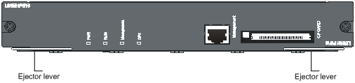
Figure-5 Reversely insert the LSWM1WCM10
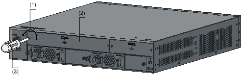
(4) Push the LSWM1WCM10 slowly along the guide rails (see callout (3) in Figure-6) and then push the ejector levers inward to lock the LSWM1WCM10 in position (see callout (4) in Figure-6).
Figure-6 Install the LSWM1WCM10 to the switch
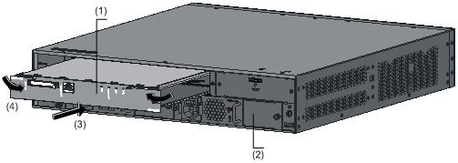
(1) LSWM1WCM10 | (2) Rear panel of the switch |
(3) Insertion direction of the LSWM1WCM10 | (4) Inward direction |
![]()
When installing the LSWM1WCM10, note the following:
l Do not touch the surface-mounted components directly with your hands.
l Do not use excessive force while installing the LSWM1WCM10. If you cannot insert the LSWM1WCM10 smoothly, check whether the installation mode is correct.
(5) Fasten the captive screws on the LSWM1WCM10 clockwise with the Philips screwdriver until the LSWM1WCM10 is fixed into the chassis.
Removing the LSWM1WCM10
(1) Wear an ESD-preventive wrist strap, ensure a good skin contact and make sure that the ESD-preventive wrist strap is properly grounded.
(2) Loosen the captive screws on the LSWM1WCM10 counterclockwise with the Philips screwdriver until all spring pressure is released.
(3) Hold each ejector lever with a hand and pull the ejector levers outward (see callout (4) in Figure-7). Then pull out the LSWM1WCM10 slowly along the guide rails (see callout (3) in Figure-7).
Figure-7 Remove the LSWM1WCM10
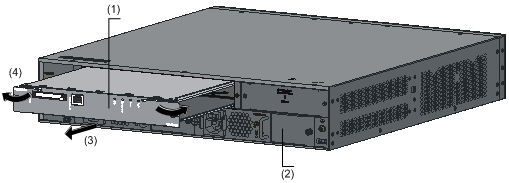
(1) LSWM1WCM10 | (2) Rear panel of the switch |
(3) Pull-out direction of the LSWM1WCM10 | (4) Outward direction of the ejector levers |
![]()
The protection panel on the LSWM1WCM10 surface has a yellow warning label  , indicating that this area corresponds to the inner heat radiator. After the LSWM1WCM10 runs for a period of time, this area may be very hot. So keep your hands away from the area while removing the LSWM1WCM10 to avoid being hurt.
![]()
If you do not install a new LSWM1WCM10 in the slot, install a filler panel to prevent dust from entering the switch and ensure normal ventilation in the switch.
5 Upgrading the LSWM1WCM10
The LSWM1WCM10 has its own Boot ROM program and application program with a Boot ROM menu different from that of the S5800-60C-PWR and S5820X-28C series switches. To update the application program of the LSWM1WCM10, use one of the following ways:
(1) Local update through the Boot ROM menu
l Use the TFTP protocol through the 10/100/1000Base-TX Ethernet port of the LSWM1WCM10
l Use the FTP protocol through the 10/100/1000Base-TX Ethernet port of the LSWM1WCM10
(1) Remote update through CLI
l Use the FTP protocol through the Ethernet port of the switch where the LSWM1WCM10 resides
l Use the TFTP protocol through the Ethernet port of the switch where the LSWM1WCM10 resides
![]()
For how to upgrade the LSWM1WCM10, refer to H3C Access Controller Module Software Maintenance Manual.
6 Logging In to the LSWM1WCM10
Using the following command on a switch, you can to log in to the software system of the LSWM1WCM10 (OAP card), and the switch’s command line interface (CLI) will switch to the software system operating interface of the LSWM1WCM10. Thus, you can manage the application software of LSWM1WCM10 on the switch.
Press the shortcut key Ctrl + K to return to the CLI of the switch.
Table4 Log in to the software system of the LSWM1WCM10 from a switch
To do… | Use the command… | Remarks |
Log in to the software system of the LSWM1WCM10 from a switch | mcms connect slot slot-number system system-name | Required Available in user view. |
![]()
Besides the above-mentioned OAP login method, you can log in to the LSWM1WCM10 through telent, web page, or NMS. For details, refer to the Login Volume of the H3C WX Series Access Controllers User Manual.
7 Guidelines
l If the host software version does not match the access controller module, contact the sales agent or the integrator for the right version.
l For how to upgrade the host software version, refer to the related part in the corresponding installation manual of the switch.
l The types and specifications of the access controller modules may vary with product versions. For the latest documentation, go to Technical Support & Document > Technical Documents on H3C's website at http://www.h3c.com.
8 Related Manuals
Manual | Description |
H3C WX Series Access Controllers User Manual | Provides a guide to the operation of H3C series access controller products (including access controllers, access controller modules, and the access controller engine of unified switches). It covers configurations of CLI, VLAN, system maintenance and debugging, WLAN, IPv4, IPv6, port basic configurations, multicast protocols, 802.1x, AAA, SSH, ACL, QoS, description of the acronyms used throughout the manual, and a command index. |
H3C WX Series Access Controllers Web-Based Configuration Manual | Introduces the Web-based management function of the WX series access controllers. |
H3C Access Controller Modules Software Upgrade Guide | Introduces how to upgrade the LSWM1WCM10. |
H3C S5800 Series Ethernet Switches Quick Start | Briefly introduces the appearance, installation, startup, maintenance, troubleshooting and lightning protection of the H3C S5800 series Ethernet switches. |
H3C S5800 Series Ethernet Switches Installation Manual | Elaborates the appearance, installation, startup, software loading, troubleshooting, maintenance and lightning protection of the H3C S5800 series Ethernet switches. |
H3C S5820x Series Ethernet Switches Quick Start | Briefly introduces the appearance, installation, startup, maintenance, troubleshooting and lightning protection of the H3C S5820x series Ethernet switches. |
H3C S5820x Series Ethernet Switches Installation Manual | Elaborates the appearance, installation, startup, software loading, troubleshooting, maintenance and lightning protection of the H3C S5820x series Ethernet switches. |
H3C OAP Cards User Manual | Introduces the hardware specifications and installation of firewall and wireless OAP cards in detail. |
Copyright © 2009 Hangzhou H3C Technologies Co., Ltd.
