
- Released At: 13-09-2023
- Page Views:
- Downloads:
- Table of Contents
- Related Documents
-
|
|
|
AD-WAN 6.2 Branch Solution |
|
WAN Service Configuration Guide |
|
|
|
|
Document version: 5W100-20230223
Copyright © 2023 New H3C Technologies Co., Ltd. All rights reserved.
No part of this manual may be reproduced or transmitted in any form or by any means without prior written consent of New H3C Technologies Co., Ltd.
Except for the trademarks of New H3C Technologies Co., Ltd., any trademarks that may be mentioned in this document are the property of their respective owners.
The information in this document is subject to change without notice.
Contents
Interface address and Underlay network parameter configuration
Address pool and service planning
Initial configuration on devices
Underlay configuration on the hub
RR underlay configuration description
Auto device deployment in the branch scenario
(Optional) Configure the mail server
(Optional) Create a tenant service administrator
Configure an overlay tunnel blocking policy
Add WAN networks and WAN network details
Deploy devices via USB/email or manually deploy devices
Add LAN networks and LAN network details
Check WAN service deployment state
Check LAN service deployment state
Configure manual TE by routing
Configure underlay TE by routing and route optimization
Application group traffic scheduling and visualization
Configure branch network application groups
Configure QoS management traffic policy
Configure rate limit for WAN interfaces
Configure QoS application assurance
Basic and extended O&M features
Edit homepage map settings and configure device locations
Edit the widgets to be displayed on the tenant homepage
Edit the homepage map display mode
Topology visualization and management
Device visualization and management
Link visualization and management
Role-based permission configuration
Configure permissions and domains
Upload device software version to be upgraded
Backup restoration and replacement
Back up device configuration manually
Overview
The AD-WAN branch 6.2 solution supports automated device onboarding and WAN service deployment. This document describes how to configure WAN services and contains the following contents:
· Branch devices automated onboarding through automated onboarding through ZTP and overlay service deployment.
· WAN service deployment: including traffic engineering functions and QoS services.
· Basic and extended O&M features: including homepage display, O&M visibility features, alarm settings, controller log management, hierarchical management, remote management, diagnostic tools, device upgrade, device configuration backup and restore, configuration audit, and configuration verification.
Network planning
Network diagram
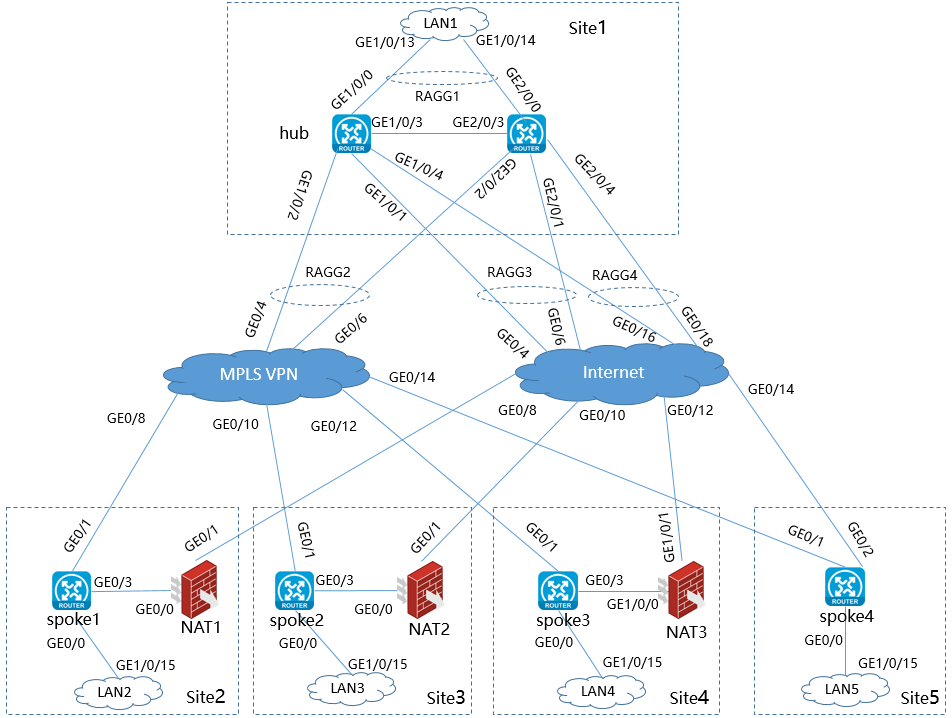
Figure 1 WAN service configuration network diagram
Network configuration
· Site1 contains two hub devices. Configure their role as RR_CPE_NAT TRANSFER. Configure dual-stack for the three WAN interfaces. Connnect one WAN interface to MPLS VPN and configure OSPF and OSPFv3. Connect the other two WAN interfaces to the Internet and configure them as the IP addresses of the STUN server.
· Site2 uses standalone device networking, and contains one device spoke1, which functions as a CPE. Configure single stack (IPv4) for the two WAN interfaces. Connnect one WAN interface to MPLS VPN and configure OSPF. Configure PPPoE dialup for the other WAN interface to connect to the Internet through dynamic NAT1.
· Site3 uses standalone device networking, and contains one device spoke2, which functions as a CPE. Configure single stack (IPv4) for the two WAN interfaces. Connnect one WAN interface to MPLS VPN and configure OSPF. Configure the other WAN interface to use DHCP and connect to the Internet through dynamic NAT2.
· Site4 uses standalone device networking, and contains one device spoke3, which functions as a CPE. Configure single stack (IPv4) for the two WAN interfaces. Connnect one WAN interface to MPLS VPN and configure OSPF. Configure the other WAN interface to use a static IP and connect to the Internet through static NAT3.
· Site5 uses standalone device networking, and contains one device spoke4, which functions as a CPE. Configure dual-stack for the two WAN interfaces. Connnect one WAN interface to MPLS VPN and configure OSPF and OSPFv3. Connect the other WAN interface to the Internet directly.
Interface address and Underlay network parameter configuration
Configure network interface addresses as shown in Table 1.
|
Device |
Interface |
Interface address |
Peer device |
Peer interface |
Peer address |
|
Hub |
Route-Aggregation2 |
80.1.1.2 8001::2 |
MPLS VPN |
Route-Aggregation2 |
80.1.1.1 8001::1 |
|
Route-Aggregation3 |
90.1.1.2 9001::2 |
Internet |
Route-Aggregation3 |
90.1.1.1 9001::1 |
|
|
Route-Aggregation4 |
90.2.1.2 9002::2 |
Internet |
Route-Aggregation4 |
90.2.1.1 9002::1 |
|
|
Route-Aggregation1.2 |
33.1.1.1 3301::1 |
LAN1 (VPN1) |
Bridge-Aggregation |
Trunk (VLAN20, VLAN21) |
|
|
Route-Aggregation1.3 |
35.1.1.1 3501::1 |
LAN1 (VPN2) |
Bridge-Aggregation |
Trunk (VLAN20, VLAN21) |
|
|
spoke1 |
GE0/1 |
80.2.1.2 |
MPLS VPN |
GE0/8 |
80.2.1.1 |
|
GE0/3 |
10.10.10.3 PPPoE dial-up |
NAT1 |
GE0/0 |
PPPoE server |
|
|
GE0/0.1 |
33.2.1.1 |
LAN2 (VPN1) |
GE1/0/15 |
Trunk (VLAN30, VLAN31) |
|
|
GE0/0.2 |
35.2.1.1 |
LAN2 (VPN2) |
GE1/0/15 |
Trunk (VLAN30, VLAN31) |
|
|
NAT1 |
GE0/0 |
PPPoE server |
spoke1 |
GE0/3 |
PPPoE |
|
GE0/1 |
90.3.1.2 |
Internet |
GE0/8 |
90.3.1.1 |
|
|
spoke2 |
GE0/1 |
80.3.1.2 |
MPLS VPN |
GE0/10 |
80.3.1.1 |
|
GE0/3 |
20.20.20.2 DHCP |
NAT2 |
GE0/0 |
DHCP Server |
|
|
GE0/0.1 |
33.3.1.1. |
LAN3 (VPN1) |
GE1/0/16 |
Trunk (VLAN40, VLAN41) |
|
|
GE0/0.2 |
35.3.1.1. |
LAN3 (VPN2) |
GE1/0/16 |
Trunk (VLAN40, VLAN41) |
|
|
NAT2 |
GE0/0 |
DHCP Server |
spoke2 |
GE0/3 |
Adding the DHCP server |
|
GE0/1 |
90.4.1.2 |
Internet |
GE0/10 |
90.4.1.1 |
|
|
spoke3 |
GE0/1 |
80.4.1.2 |
MPLS VPN |
GE0/12 |
80.4.1.1 |
|
GE0/3 |
30.30.30.2 |
NAT3 |
GE1/0/0 |
30.30.30.1 |
|
|
GE0/0.1 |
33.4.1.1 |
LAN4 (VPN1) |
GE1/0/17 |
Trunk (VLAN50, VLAN51) |
|
|
GE0/0.2 |
35.4.1.1 |
LAN4 (VPN2) |
GE1/0/17 |
Trunk (VLAN50, VLAN51) |
|
|
NAT3 |
GE1/0/0 |
30.30.30.1 |
spoke3 |
GE0/3 |
30.30.30.2 |
|
GE1/0/1 |
90.5.1.2 |
Internet |
GE0/12 |
90.5.1.1 |
|
|
spoke4 |
GE0/1 |
80.5.1.2 8005::2 |
MPLS VPN |
GE0/14 |
80.5.1.1 8005::1 |
|
GE0/2 |
90.6.1.2 9006::2 |
Internet |
GE0/14 |
90.6.1.1 9006::1 |
|
|
GE0/0.1 |
33.5.1.1 3305::1 |
LAN5 (VPN1) |
GE1/0/18 |
Trunk (VLAN60, VLAN61) |
|
|
GE0/0.2 |
35.1.1.1 3505::1/64 |
LAN5 (VPN2) |
GE1/0/18 |
Trunk (VLAN60, VLAN61) |
Table 2 NAT mappings
|
Device |
Protocol |
External port |
Internal port |
Purposes |
Remarks |
|
Firewall |
TCP |
19443 |
Controller northbound virtual address: 19443 |
WebSocket registration |
In the network, you cannot configure NAT for address translation for the RRs. |
|
TCP |
35000 |
Controller northbound virtual address: 35000 |
Device configuration backup and upgrade |
Address pool and service planning
Before starting automated device onboarding, you must plan the network to request the resource pools for the network. See Table 3.
Table 3 Address pool requirements and planning
|
Address pool |
Resources required |
Address pool plan |
|
Management interface address pool |
Addresses are automatically allocated by the address pool or manually assigned. If addresses are allocated by the address pool, the required number of addresses is the actual number of devices. |
Assume that 10 devices will be deployed. The address pool must contain a minimum of 10 addresses. Address pool: 30.1.1.1 to 30.1.1.10 Mask length: 24 |
|
LAN service address pool |
Addresses are automatically allocated by the address pool or manually assigned. If addresses are allocated by the address pool, the required number of addresses is: Maximum number of access endpoints of a single LAN network rounded up to the next power of 2 × number of LAN networks × maximum number of devices × maximum number of LAN interfaces on a single device. |
Assume that 10 devices will be deployed, each device has a LAN network and a LAN interface, and a LAN network provides access to a maximum of 50 endpoints (64 endpoints, rounded up to the next power of 2). The minimum number of addresses needed is 64×10×1×1=640. Address pool: 172.31.1.0 to 172.31.3.0 Mask length: 16 |
|
|
CAUTION: All resource pools support expansion. As a best practice, make sure the initial deployment of the resource pools meets the current network requirements. |
Service simulation
When you configure QoS component services, you must simulate the effect of the application traffic verification feature, as shown in Table 4.
Table 4 Service network simulation
|
Service network |
Simulator |
Remarks |
|
LAN1 |
Switch SW |
Configure VLAN 20 for VPN 1 service and VLAN 21 for VPN 2 service. |
|
LAN2 |
Switch SW |
Configure VLAN 30 for VPN 1 service and VLAN 31 for VPN 2 service. |
|
LAN3 |
Switch SW |
Configure VLAN40 for VPN 1 service and VLAN 41 for VPN 2 service. |
|
LAN4 |
Switch SW |
Configure VLAN 50 for VPN 1 service and VLAN 51 for VPN 2 service. |
|
LAN5 |
Switch SW |
Configure VLAN 60 for VPN 1 service and VLAN 61 for VPN 2 service. |
Initial configuration on devices
Generally, headquarters devices come online through manual deployment. You must manually configure the underlay network.
Underlay configuration on the hub
Interface configuration
#
interface Route-Aggregation1
link-aggregation mode dynamic
#
interface Route-Aggregation1.1 //Configure the interface for registration through WebSocket.
ip address 31.1.1.2 255.255.255.0
ospf 10 area 0.0.0.0 //OSPF 10, Area 0.
vlan-type dot1q vid 10
#
interface Route-Aggregation2 //Configure IPv4/IPv6 dual stack for WAN interface accessing L3VPN.
bandwidth 10000
ip address 80.1.1.2 255.255.255.0
ospf 10 area 0.0.0.10 //IPv4 OSPF 10, area 10.
ospfv3 30 area 0.0.0.0 //IPv6 OSPFv3 30, area 0.
link-aggregation mode dynamic
ipv6 address 8001::2/64
#
interface Route-Aggregation3 //Configure IPv4/IPv6 dual stack for WAN interface accessing the Internet.
bandwidth 10000
ip address 90.1.1.2 255.255.255.0
ipv6 address 9001::2/64
#
interface Route-Aggregation4 //Configure IPv4/IPv6 dual stack for WAN interface accessing the Internet.
bandwidth 10000
ip address 90.2.1.2 255.255.255.0
link-aggregation mode dynamic
ipv6 address 9002::2/64
#
IRF configuration
#
irf mac-address persistent timer
irf auto-update enable
irf auto-merge enable
undo irf link-delay
irf member 1 priority 1
irf member 2 priority 1
#
irf-port 1/2
port group interface GigabitEthernet1/0/3
#
irf-port 2/1
port group interface GigabitEthernet2/0/3
#
Routing configuration
#
ospf 10
area 0.0.0.0
area 0.0.0.10
#
ospfv3 30
router-id 80.1.1.2 //You must configure a router ID separately for each OSPFv3 process.
area 0.0.0.0
#
NTP time synchronization configuration
#
clock protocol ntp
#
#
ntp-service enable
ntp-service unicast-Server 192.168.40.127 // You must configure time synchronization for all devices in the network.
#
RR underlay configuration description
If an RR has multiple WAN interfaces, CPEs will send TLS link establishment requests to the WAN interfaces. The reply packets sent by the RR must follow the same route as the request packet. You must add the following configuration on the WAN interfaces.
#
interface GigabitEthernet3/4/2
ip last-hop hold
#
Auto device deployment in the branch scenario
Configuration workflow
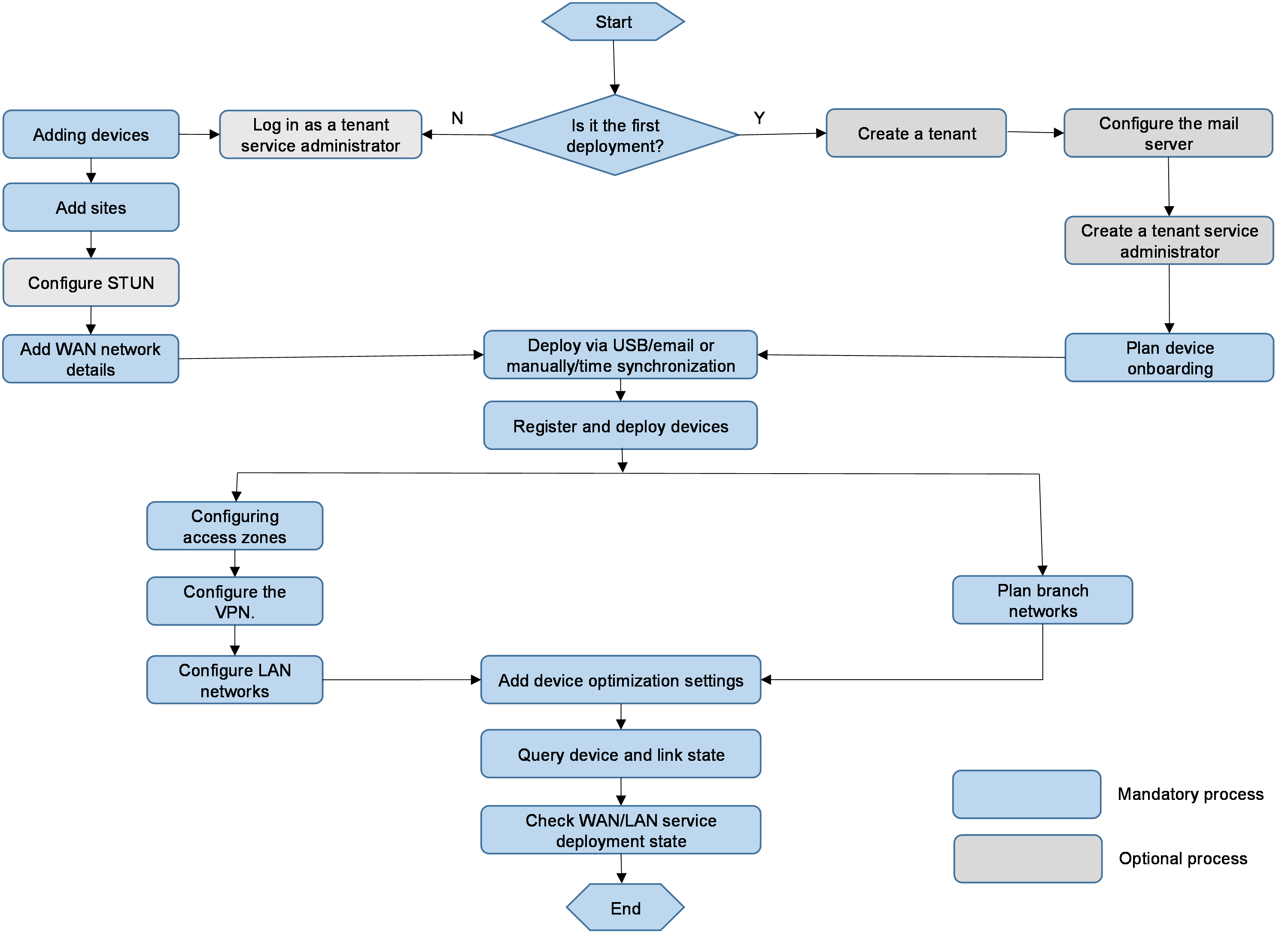
Auto device deployment in the branch scenario includes the following steps:
1. Register and deploy all devices according to the configuration and network. Manually deploy the hub devices in the headquarters. Deploy branch devices through the USB flash drive or email.
2. Deploy WAN and LAN services: After devices are registered and come online, the controller deploys WAN services and LAN services, including overlay tunnels and LAN interfaces.
Figure 2 shows the detailed configuration flowchart.
Figure 2 Configuration workflow
Log in to Unified Platform
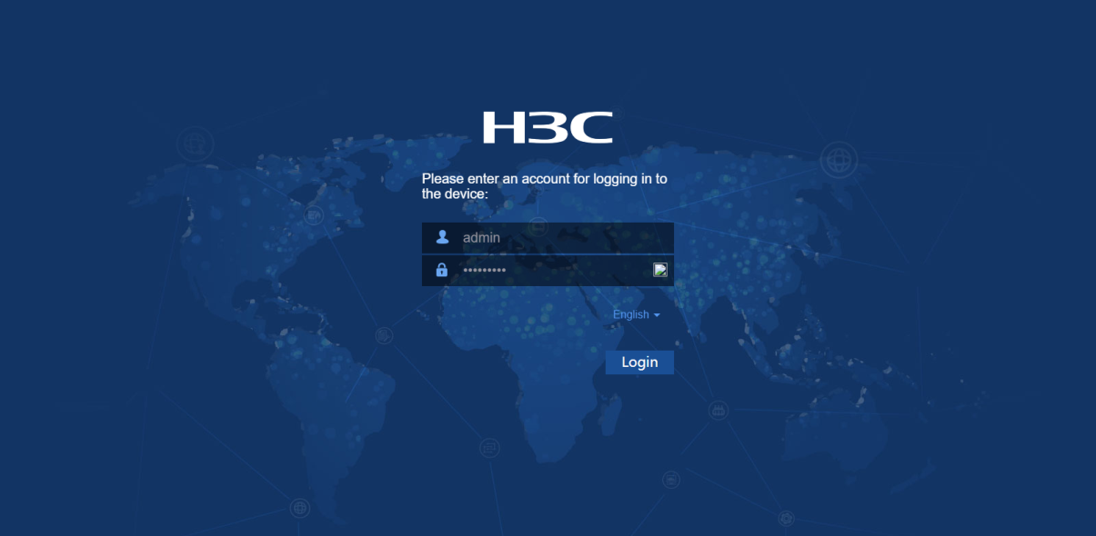
1. In the address bar of the browser, enter the login address (the default is http://ip_address:30000/central) of Unified Platform, and then press Enter to access the login page as shown in Figure 3. The ip_address parameter specifies the northbound service VIP of the cluster of the Matrix where Unified Platform is installed. The port number is 30000.
2. Enter the operator’s username and password. The default username is admin, and the default password is Pwd@12345. You can perform service configuration by using the default username or logging in as a manually created tenant service administrator.
Figure 3 Unified Platform login page

(Optional) Configure the mail server
To perform deployment via email, you must first configure the mail server. Skip this step if you do not perform deployment via email.
1. Log in to Unified Platform as the default administrator (admin), and navigate to the System > System Settings > Mail Server Settings page.
2. Enter the mail server address, server port number (25 by default), username and password for authentication, and sender's mail address, as shown in Figure 4. Click OK.
Figure 4 Configuring mail server information
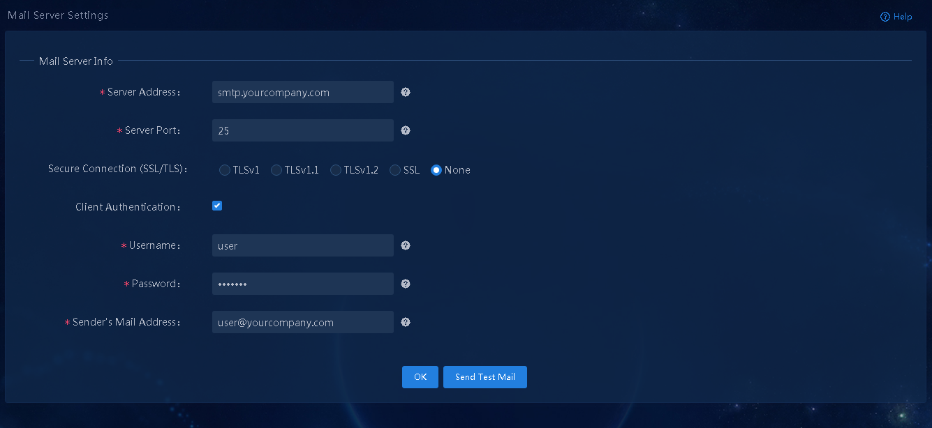
3. After the configuration is completed, click Send Test Mail to send a test mail to the recipient to identify whether the mail server configuration is correct.
(Optional) Create a tenant
After the controller is installed, a tenant named System is automatically created. You can use the system administrator account (admin) of tenant System to incorporate devices and deploy services.
Alternatively, you can manually create a tenant, and incorporate devices and deploy services as the new tenant.
1. Log in to Unified Platform as the default system administrator admin and then navigate to the System > Tenants > Tenants page, as shown in Figure 5.
Figure 5 Tenant management page
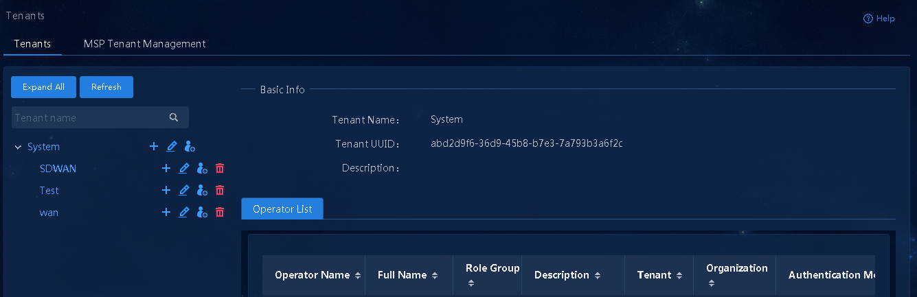
2. Click the ![]() icon to the right of the tenant named System.
Add a new tenant, and then click
OK, as shown in Figure 6.
icon to the right of the tenant named System.
Add a new tenant, and then click
OK, as shown in Figure 6.
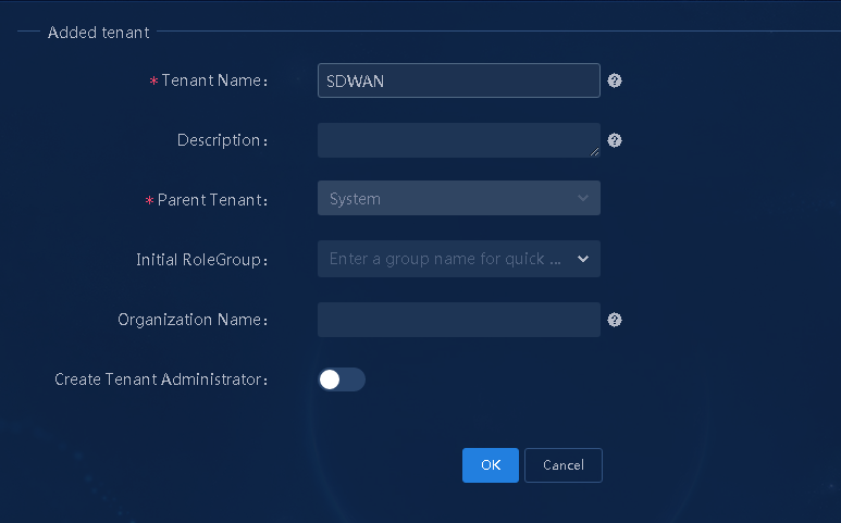
Parameters:
¡ Tenant Name: Enter the name of the created tenant (SDWAN in this example).
¡ Initial RoleGroup: Select a preset group for the tenant. Options include System Manager Group, System Viewer Group, Service Manager Group, and Service Viewer Group. If you select the Create Tenant Administrator parameter, you must select System Manager Group. By default, all the preset groups are selected.
¡ Create Tenant Administrator: Select whether to create a tenant administrator. If you enable this parameter, you add an operator as the tenant's system administrator.
(Optional) Create a tenant service administrator
When a tenant is created, you must first create a tenant service administrator to deploy services.
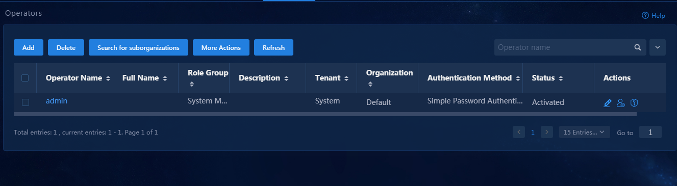
1. Log in to Unified Platform as the default system administrator admin. After logging in to Unified Platform, navigate to the System > Operators > Operator List page, as shown in Figure 7. On this page, you can see the list of all operators.
2. Click Add. In the dialog box that opens, configure related parameters, and then click OK, as shown in Figure 8.
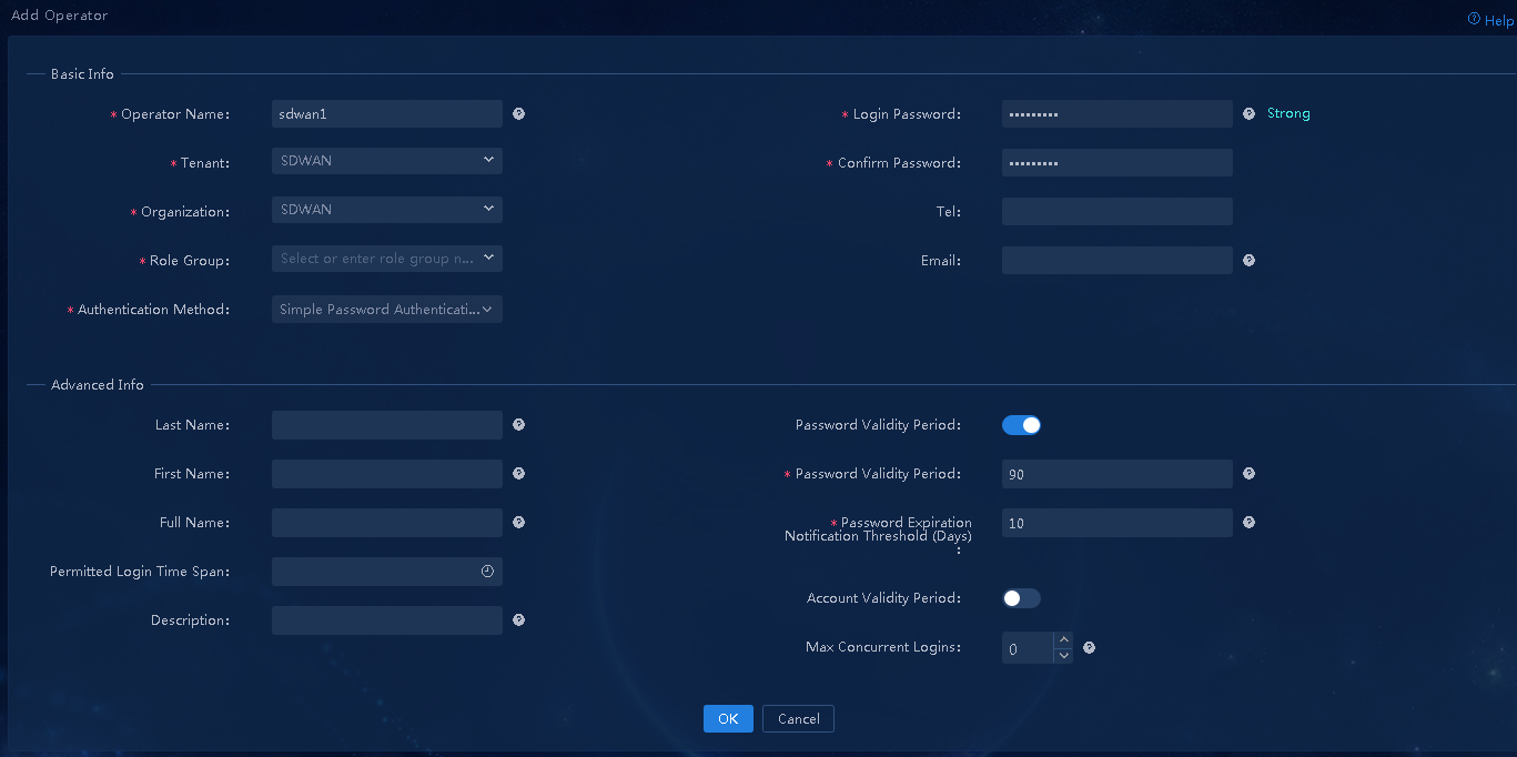
Parameters:
¡ Operator Name: Enter the username of the operator used for login, sdwan1 in this example.
¡ Tenant: Tenant used to incorporate devices and deploy services. You can select the tenant named SDWAN created in "(Optional) Create a tenant."
¡ Role Group: The system offers four preset groups. In this example, select Service Manager Group to assign the operator the permissions in the service administrator group.
¡ Authentication Method: Options include Simple Password Authentication, RADIUS Authentication, LDAP Authentication, TACACS Authentication, and Third-Party Authentication. In this example, select Simple Password Authentication, and set the login password.
Plan device onboarding
If you configure the service for the first time, first complete the deployment guide. In this section, log in to Unified Platform as the tenant service administrator named sdwan1. For tenant related configurations, see "(Optional) Create a tenant" and "(Optional) Create a tenant service administrator."
Global config
Configure basic settings
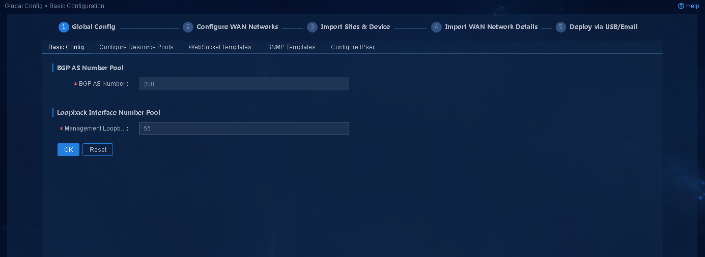
Navigate to the Guide > Branch Network Deployment > Plan Device Onboarding > Global Config > Basic Configuration page, configure BGP AS Number and Management Loopback Interface Number, as shown in Figure 9, and then click OK.
Figure 9 Configuring basic settings
Configure resource pools
1. Navigate to the Guide > Branch Network Deployment > Plan Device Onboarding > Global Config > Configure Resource Pools page. When you configure address pools, you can click Calculate Address Pool to calculate the address pool settings, as shown in Figure 10. Click OK.
Figure 10 Configuring resource pools
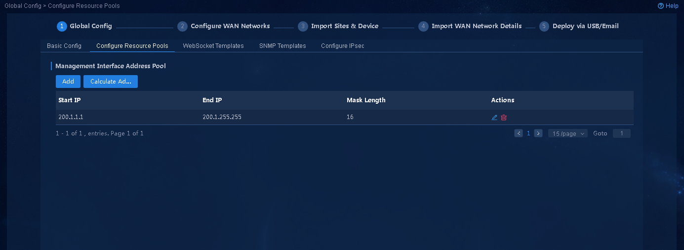
Parameters:
¡ Management Interface Address Pool: Address pool used to assign management IP addresses to devices. You can manually specify management IP addresses for devices. When you manually specify management IP addresses, you do not need to configure this address pool.
¡ LAN Address Pool (IPv4): DHCP address pool used to assign IP addresses to LAN interfaces. The system can automatically split the address pool according to the number of access devices. When you deploy a LAN service, you can also manually specify a DHCP address pool. When you manually specify a DHCP address pool, you do not need to configure this address pool.
¡ LAN Address Pool (IPv6): DHCPv6 address pool used to assign IP addresses to LAN interfaces. The system can automatically split the address pool according to the number of access devices. When you deploy a LAN service, you can also manually specify a DHCPv6 address pool. When you manually specify a DHCPv6 address pool, you do not need to configure this address pool.
2. After the configuration guide is completed, view the resource pools on the Automation > Branch Network > Parameter Settings > Pools > IP Address Pools page. On this page, you can also expand the resource pools.
WebSocket template
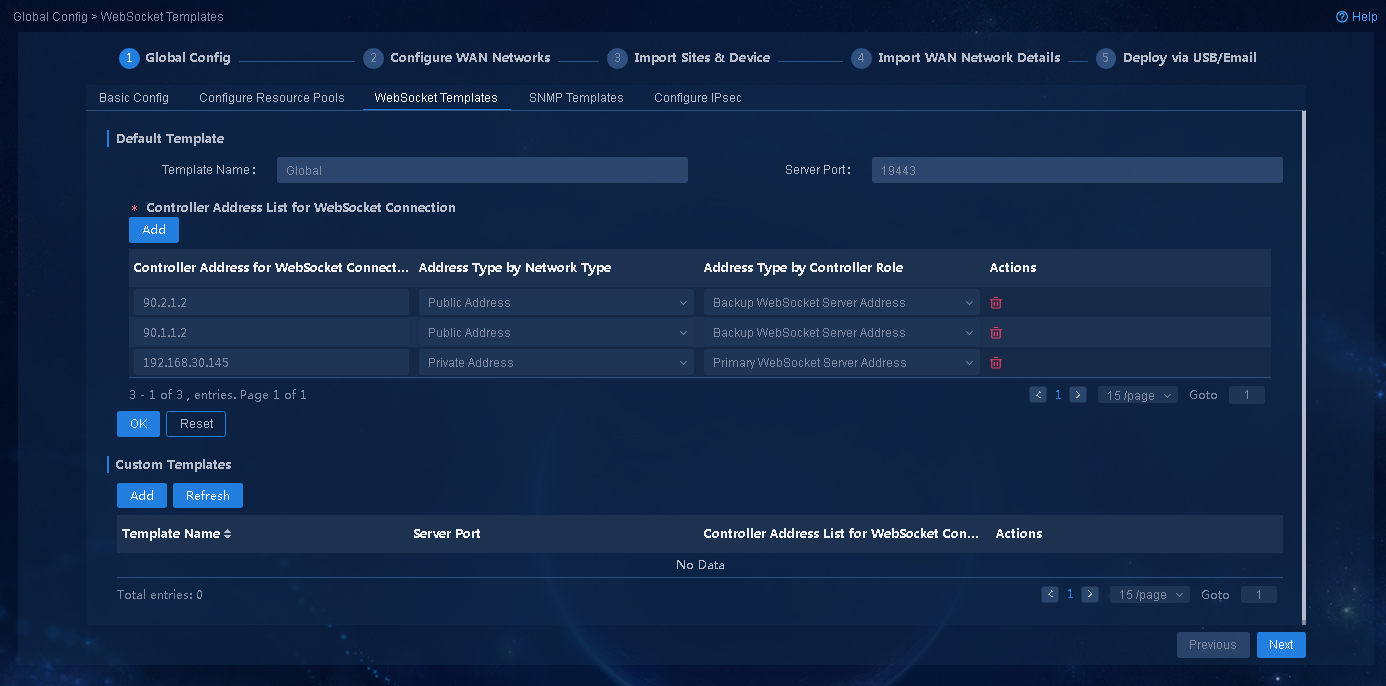
1. Navigate to the Guide > Branch Network Deployment > Plan Device Onboarding > Global Config > WebSocket Templates page. On this page, configure a WebSocket template, as shown in Figure 11, and then click OK. The address of the global default template is the northbound VIP. For devices come online through the public network, you can add a public network address in the global template or add a new template. In this example, two public IP addresses for registration are added, 90.1.1.2 and 90.2.1.2.
Figure 11 Configuring WebSocket templates
2. After the configuration guide is completed, view the corresponding templates on the Automation > Branch Network > Templates > WebSocket Templates page. On this page, you can also edit WebSocket templates.
To deploy a 3+3 disaster recovery network, you must also add the northbound address of the disaster recovery cluster as the backup server address.
Configure SNMP templates
1. Navigate to the Plan Device Onboarding > Global Config > SNMP Templates page. By default, no SNMP template is configured. To deploy SNMP configuration to devices, you can click Add to add an SNMP template. When you add a new SNMP template, select SNMP version v2c, set the read community name to pubic, and set the write community to private, as shown in Figure 12.
Figure 12 Configuring SNMP templates

2. After the configuration guide is completed, you can see the corresponding templates on the Automation > Branch Network > Templates > SNMP Templates page. On this page, you can also edit SNMP templates.
Configure IPsec
1. Navigate to the Guide > Branch Network Deployment > Plan Device Onboarding > Global Config > Configure IPsec page. On this page, you can select an encryption scheme. In this example, select Recommended Encryption Scheme, as shown in Figure 13, and then click OK to save the configuration.
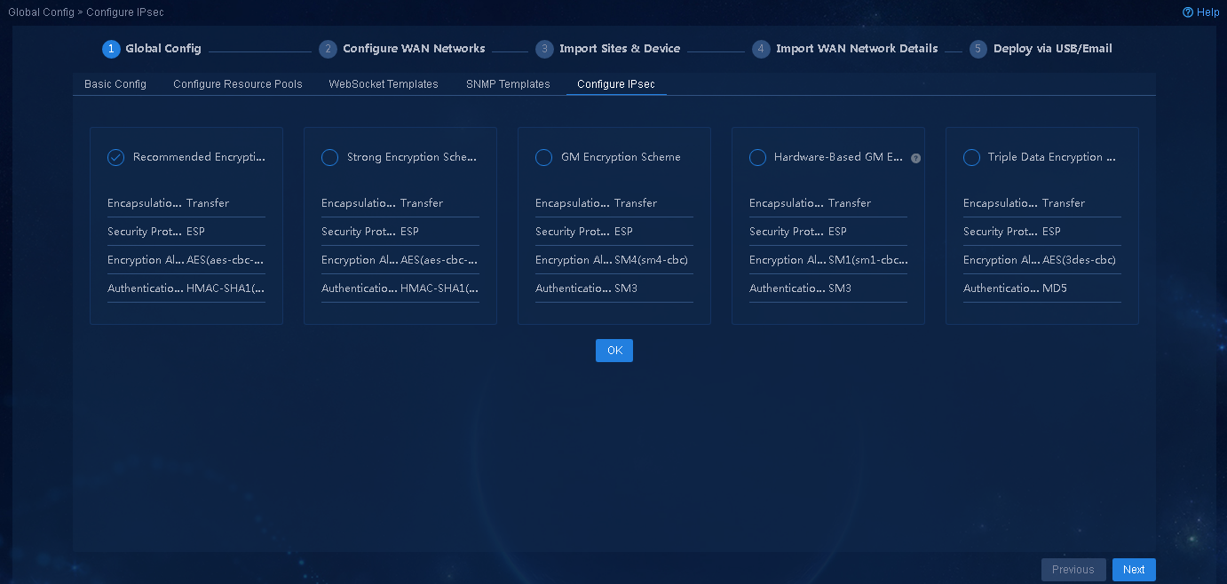
2. After the configuration guide is completed, view the corresponding IPsec encryption scheme on the Automation > Branch Network > Virtual Network > Configure IPsec page. After all WAN details are deleted, you can edit the IPsec encryption scheme.
|
|
CAUTION: · You can select only one IPsec encryption scheme for the network. · The GM encryption scheme must use dedicated GM encryption modules. For a successful IPsec tunnel establishment and traffic forwarding, make sure all devices that need to establish IPsec tunnels have GM encryption modules if you select this scheme. |
3. After completing global config, click Next to access the Configure WAN Networks page.
Configure WAN Networks
Configure WAN service networks of the Internet role
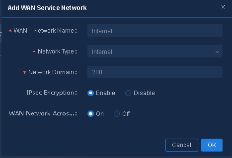
1. Navigate to the Guide > Branch Network Deployment > Plan Device Onboarding > Configure WAN Networks page. Click Add to add WAN service networks as needed, as shown in Figure 14, and then click OK to save the configuration. For example, configure the WAN network name as internet and select network type Internet.
Figure 14 Adding WAN service networks of the Internet role
Parameters:
¡ IPsec Encryption: Enable or disable IPsec encryption. In this example, IPsec encryption is enabled.
¡ Network Domain: Specify the number of network domains. The maximum number of network domains for tenants is 65535 (in the range of 1 to 65535). Tunnels can be established between WAN networks with the same network domain. The network domain is set to 200 in this example.
¡ Access POP Site: Configure the WAN network to connect to one or more sites in the access area.
¡ WAN Network Across Transmission Switch: Enable or disable this parameter. If it is enabled, different transport networks can establish a TTE association.
2. Configure the name of the transport network.
Click the ![]() icon in the Actions column to access the path sets configuration page, as shown in Figure 15.
Different interfaces connecting a device to the same service network must belong to different transport networks.
icon in the Actions column to access the path sets configuration page, as shown in Figure 15.
Different interfaces connecting a device to the same service network must belong to different transport networks.
Figure 15 Transport network list

Parameters:
¡ Transport Network: By default, a transport network named Default exists. You can add or delete a transport network as needed. Different WAN access interfaces of a device must belong to different transport networks. An English name is supported.
¡ Transport Network Alias: The alias of a transport network. A Chinese alias is supported.
Different WAN service networks of a tenant must be configured with different route domains. Different transport networks must be configured for the same device to access the same route domain.
Configure WAN service networks of the L3VPN role
1. Configure the service network name as MV, select the network role L3VPN, and configure related parameters as shown in Figure 16, and then click OK.
Figure 16 Adding WAN service networks of the L3VPN role
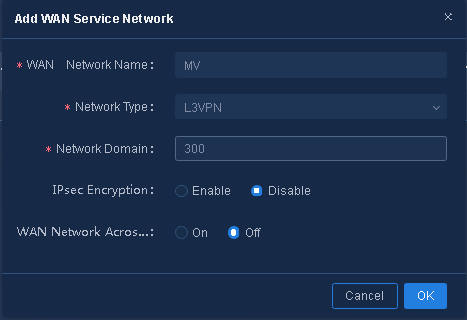
Parameters:
¡ IPsec Encryption: Enable or disable IPsec encryption. In this example, IPsec encryption is disabled.
¡ Network Domain: Specify the number of network domains. The maximum number of network domains for tenants is 65535 (in the range of 1 to 65535). Tunnels can be established between WAN networks with the same network domain. The network domain is set to 300 in this example.
¡ Access POP Site: Configure the WAN network to connect to one or more sites in the access area.
¡ WAN Network Across Transport Network: Enable or disable this parameter. If it is disabled, only the same transport networks can establish a TTE association.
2. Configure the name of the transport network, as shown in Figure 17. Different interfaces connecting a device to the same service network must belong to different transport networks.
Figure 17 Transport network list
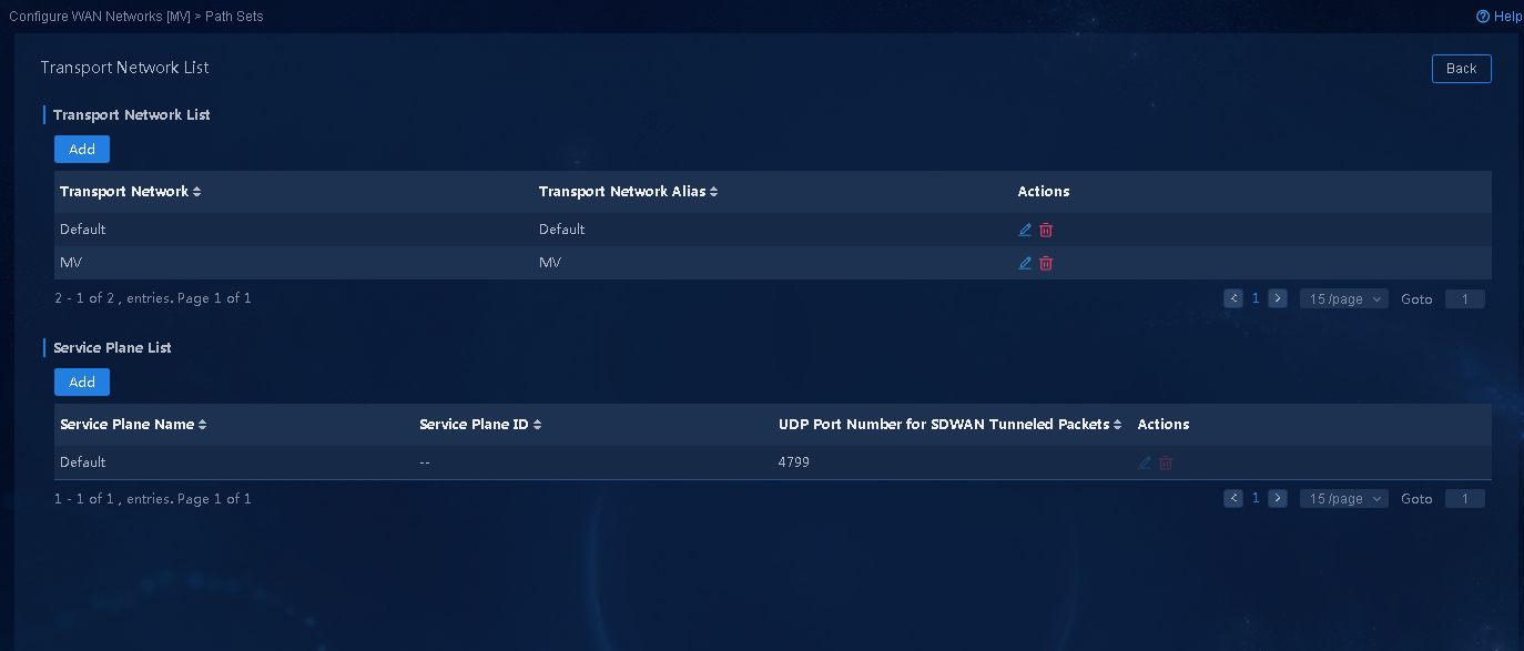
¡ Transport Network: By default, a transport network named Default exists. You can add or delete a transport network as needed. Different WAN access interfaces of a device must belong to different transport networks. An English name is supported.
¡ Transport Network Alias: The alias of a transport network. A Chinese alias is supported.
Import sites and devices
Import sites and devices
1. On the Import Sites and Devices page, click Download Template to download a template, and follow the instructions to enter device information in the template as shown in Figure 18.
Figure 18 Device import template remarks
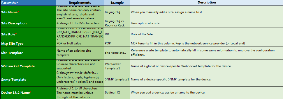
Parameters:
¡ Site Name: Name of a site, a string of 1 to 255 characters. The site name can only contain English letters, digits and dots (.) and must be unique.
¡ Site Role:
- RR: Router reflector.
- CPE: Customer premises equipment.
- NAT_TRANSFER: NAT transfer device.
- RR_CPE: Router reflector and customer premises equipment.
- RR_NAT_TRANSFER: Router reflector and NAT transfer device.
- CPE_NAT_TRANSFER: Customer premises equipment and NAT transfer device.
- RR_CPE_NAT_TRANSFER: Router reflector, customer premises equipment, and NAT transfer device.
- In a network, the configuration of NAT_TRANSFER role depends on the NAT type. See Table 5.
¡ Site Type: Router or firewall.
¡ Management IP Address: The address is allocated from the management IP address pool. If you do not configure a management IP address pool, you must manually specify the management IP address.
¡ Device Serial Number: It is a required field. You can input multiple serial numbers separated by semicolons (;) in the field. In this field, you must input the serial numbers of hosts. For an IRF fabric, you must input the serial numbers of the two IRF member devices. To obtain the serial numbers of IRF member devices, execute the following commands (the commands might vary with device models):
display license device-id (fixed-port device)
display license device-id slot 1/2 (fixed-port device)
display license device-id chassis 1/2 (modular device)
For example, execute the following command to obtain the serial number of the hub, and input the result in the Excel import template.
<hub>dis license device-id slot 1
SN: 210235A1X5M168A00057
Device ID: pYw5-FWs7-H7PX-m6N@-iu@i-3Chd-3Squ-677n
<hub>dis license device-id slot 2
SN: 2102111111A129000001
Device ID: MAj3-VkTY-jr>D-hnx$-6m9j-wP%y-6PaF-PWw/
Table 5 Combination of NAT types in SDWAN network
|
CPE 1 NAT type |
CPE 2 NAT type |
Support tunnel establishment between CPEs |
Deploy NAT Transfer for interworking between CPEs |
|
No NAT |
Full cone NAT |
√ |
× |
|
No NAT |
Port restricted cone NAT/Restricted cone NAT |
√ |
× |
|
No NAT |
Symmetric NAT |
√ |
× |
|
No NAT |
Unknown NAT |
√ |
× |
|
No NAT |
Static NAT |
√ |
× |
|
Full cone NAT |
Full cone NAT |
√ |
× |
|
Full cone NAT |
Port restricted cone NAT/Restricted cone NAT |
√ |
× |
|
Full cone NAT |
Symmetric NAT |
√ |
× |
|
Full cone NAT |
Unknown NAT |
√ |
× |
|
Full cone NAT |
Static NAT |
√ |
× |
|
Port restricted cone NAT/Restricted cone NAT |
Port restricted cone NAT/Restricted cone NAT |
× |
√ |
|
Port restricted cone NAT/Restricted cone NAT |
Symmetric NAT |
× |
√ |
|
Port restricted cone NAT/Restricted cone NAT |
Unknown NAT |
× |
√ |
|
Port restricted cone NAT/Restricted cone NAT |
Static NAT |
√ |
× |
|
Symmetric NAT |
Symmetric NAT |
× |
√ |
|
Symmetric NAT |
Unknown NAT |
× |
√ |
|
Symmetric NAT |
Static NAT |
√ |
× |
|
Unknown NAT |
Unknown NAT |
× |
√ |
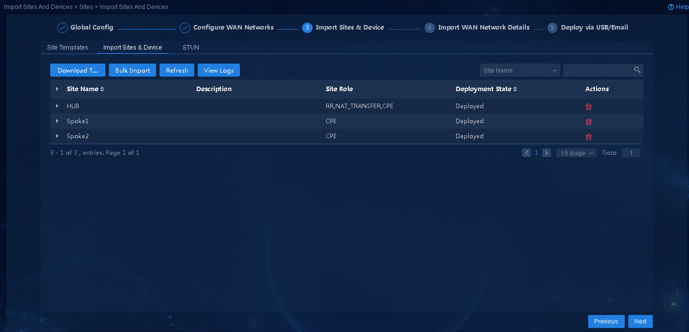
2. After devices are imported, as shown in Figure 19, click Next to access the Import Sites page.
Figure 19 Importing sites and devices
|
|
CAUTION: To delete sites and devices, you must log in to Unified Platform as admin, and delete resources on the System > System Settings > Resources page. |
(Optional) Configure STUN
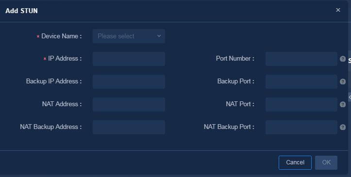
Navigate to the Guide > Branch Network Deployment > Plan Device Onboarding > Import Sites and Devices > STUN page, click Add, and configure the STUN server as shown in Figure 20. If no NAT exists in the network, skip this step.
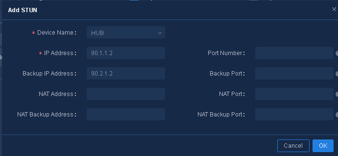
Parameters:
· IP Address: Enter the IP address of the STUN server.
· Port Number: Enter the port number of the STUN server. The port number must be in the range of 1024 to 65535, and the default value is 3478.
· Backup IP Address: Enter the backup IP address of the STUN server.
· Backup Port Number: Enter the backup port number of the STUN server. The backup port number must be in the range of 1024 to 65535, and the default value is 3479.
· NAT Address: Enter the public IP address of the STUN server after a NAT.
· NAT Port: Enter the public port number of the STUN server after a NAT. The port number must be in the range of 1024 to 65535, and the default value is the port number of the STUN server.
· NAT Backup Address: Enter the NAT backup IP address.
· NAT Backup Port: Enter the backup public port number of the STUN server after a NAT. The port number must be in the range of 1024 to 65535, and the default value is the backup port number of the STUN server.
|
|
CAUTION: · You cannot edit the STUN once it is set. If you need to edit it, you must delete the STUN first and add it again. · If a device uses a private network address, you must configure a STUN server to determine the IP address and port number after a NAT. · To ensure the normal operation of the STUN, make sure the STUN client can reach the IP address and the backup address. |
Import WAN network details
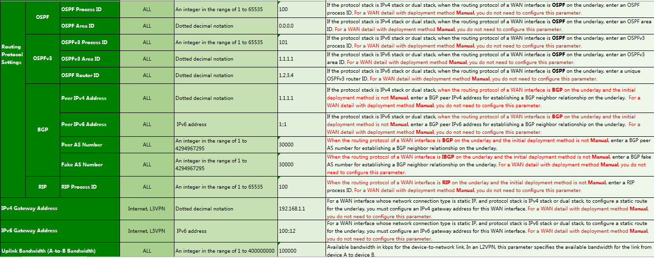
1. Navigate to the Guide > Branch Network Deployment > Plan Device Onboarding > Import WAN Network Details page, click Download Template to download a template, and follow the instructions to enter WAN network detail information in the template as shown in Figure 21, Figure 22, and Figure 23.
Figure 21 Guidelines for importing WAN network details-1
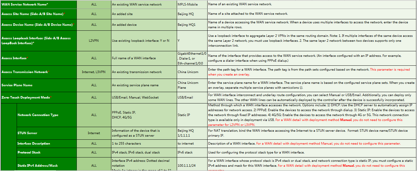
Figure 22 Guidelines for importing WAN network details-2
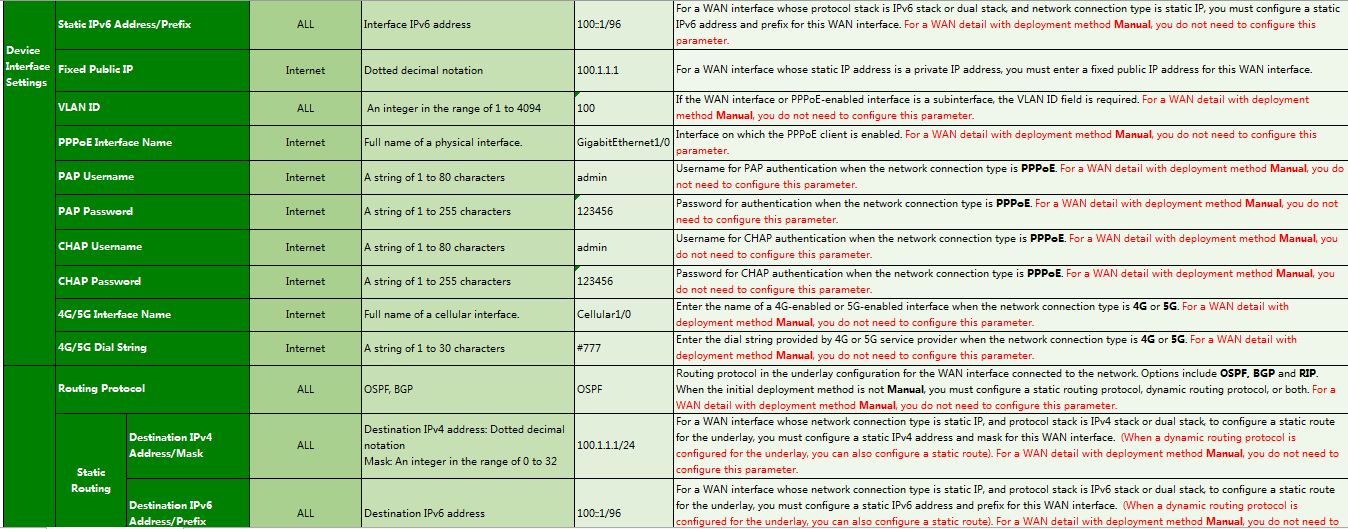
Figure 23 Guidelines for importing WAN network details-3
Parameters:
¡ Access Interface: Name of the interface that provides access to the WAN network. You must specify an interface configured with an IP address. For example, configure a dialer interface when using PPPoE dialup.
¡ Access Transport Network: Name of the created transport network.
¡ Deployment Mode:
- USB/Email: Generate the deployment configuration corresponding to the USB flash drive or mail. The device can register and come online through this WAN interface. The interface address, access method, and related routing protocol must be configured. Typically, this method is used in zero-touch deployment for branches.
- WebSocket: In this way, the deployment configuration corresponding to the USB flash drive or mail is not generated, and the device does not register or come online through this WAN interface. After the device comes online, the corresponding configuration is deployed to the device through WebSocket. The interface address, access method, and related routing protocol must be configured.
- Manual: Manually configure the interface address and routing protocols. Typically, use this mode for devices in the HQ (non-zero-touch deployment).
¡ Network Connection Type: Method through which a WAN interface accesses the network. Options are:
- DHCP: Use the DHCP server to automatically assign IP addresses for network access.
- PPPoE: Enable the devices to access the network through dialup.
- Static IP: Enable the devices to access the network through fixed IP addresses.
- 4G/5G: Enable the devices to access the network through 4G/5G. This option is supported only in deployment via USB.
Except Internet and 3G/4G/5G networks, for a WAN detail with the initial deployment method Manual, you do not need to configure this parameter.
¡ STUN SERVER Name: Select the previously configured STUN server.
¡ Protocol Stack Type: Protocol stack type for the WAN interface. Options include IPv4 Stack, IPv6 Stack, and Dual Stack.
¡ PPPoE Interface Name: Name of the interface on which the PPPoE client is enabled.
¡ Routing Protocol Type: Underlay routing protocol for the WAN interface accessing the network. If the network type is Internet or L3VPN, options include Static Routing, OSPF, and BGP.
¡ Gateway Address: Configure the gateway address (peer address) for the WAN interface. Routing settings are configured based on this gateway address. You do not need to configure this parameter when the interface type is Dialer, 4G Eth-channel, or 3G Serial.
¡ NAT Address: For a WAN interface on the RR with a private IP address, you must enter the corresponding fixed public IP address.
¡ Uplink/Downlink Bandwidth (kbps): Set the available bandwidth for the device to network link or network to device link. The branch solution performs scheduling based on bandwidth, and you must configure the uplink bandwidth and downlink bandwidth.
¡ MTU: MTU of the interface. By default, the interface has an MTU. As a best practice, do not set this field.
¡ TCP MSS: As a best practice, do not set this field. TCP MSS is not recommended for WAN interfaces.
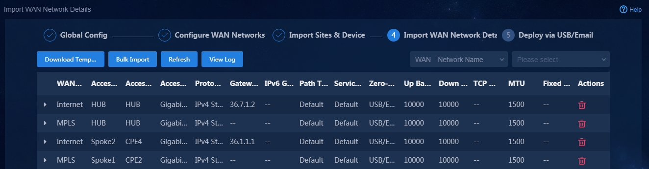
2. After the WAN network details are imported as shown in Figure 24, click Next to access the Deploy via USB/Email page.
Figure 24 Importing WAN network details
Deploy devices via USB/email
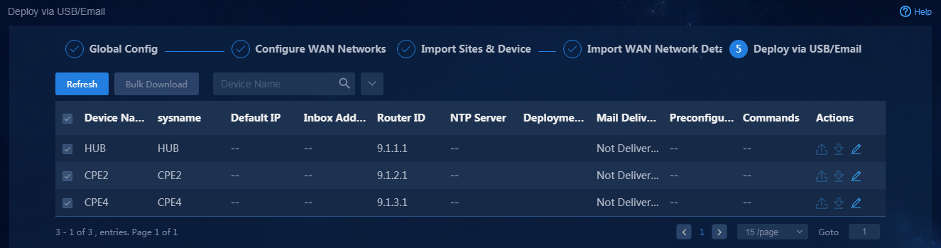
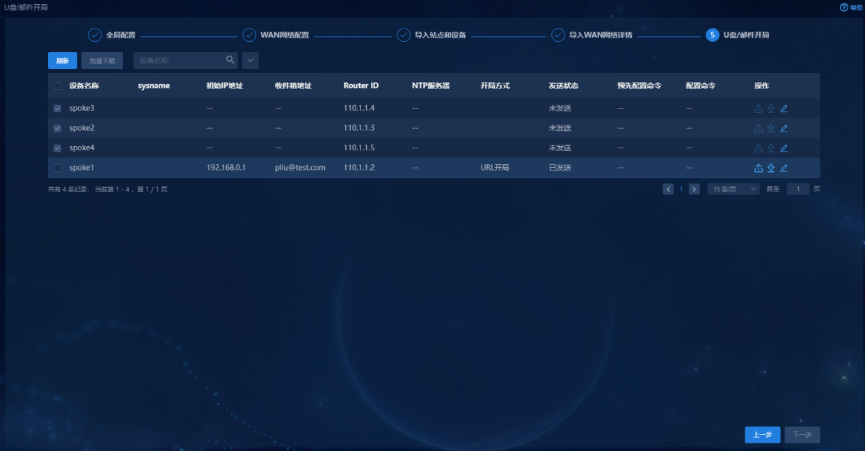
Navigate to the Guide > Branch Network Deployment > Plan Device Onboarding > Deploy via USB/Email page. On this page, the devices that support automatic deployment are displayed. These devices are devices for which deployment via USB/Email is selected when you import WAN network details, as shown in Figure 25. To use this deployment mode, you must first configure the mail server, as shown in "(Optional) Configure the mail server."
Figure 25 Deployment via USB flash drive or email
Deploy devices via email
Configure deployment via email
1. Select the device for automatic deployment (Spoke1
in this example), and click the ![]() icon in the Actions
column to access the deployment
settings page. Select Deploy via URL for Deployment Method,
configure required parameters, as shown in Figure 26, and
then click OK to save the configuration.
icon in the Actions
column to access the deployment
settings page. Select Deploy via URL for Deployment Method,
configure required parameters, as shown in Figure 26, and
then click OK to save the configuration.
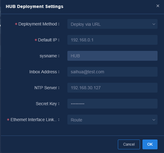
Parameters:
¡ Default IP: Default interface IP address of a device after the device is powered on. The IP address is used to receive the URL for deployment. Typically, the default IP address is 192.168.0.1.
¡ Inbox Address: Email address used for receiving the deployment URL.
¡ NTP Server: Configure the NTP server address. You must perform NTP time synchronization for devices in the network. You can use the northbound IP address of the controller to synchronize time with the controller.
¡ Secret Key: Deployment via URL supports encryption. If you do not configure a secret key, the URLs used for deployment are not encrypted. If you configure a secret key, the secret key is used for encrypting the URLs used for deployment. In this example, the secret key is set to Pwd@12345.
¡ Ethernet Interface Link Mode: Options include Default and Route. In this example, the default route mode is used. The link mode of an Ethernet-type WAN interface is automatically switched to route mode. For VSR devices, you must use the default mode, and interfaces do not support the route mode.
2. Obtain the URLs for deployment by using one of the following methods:
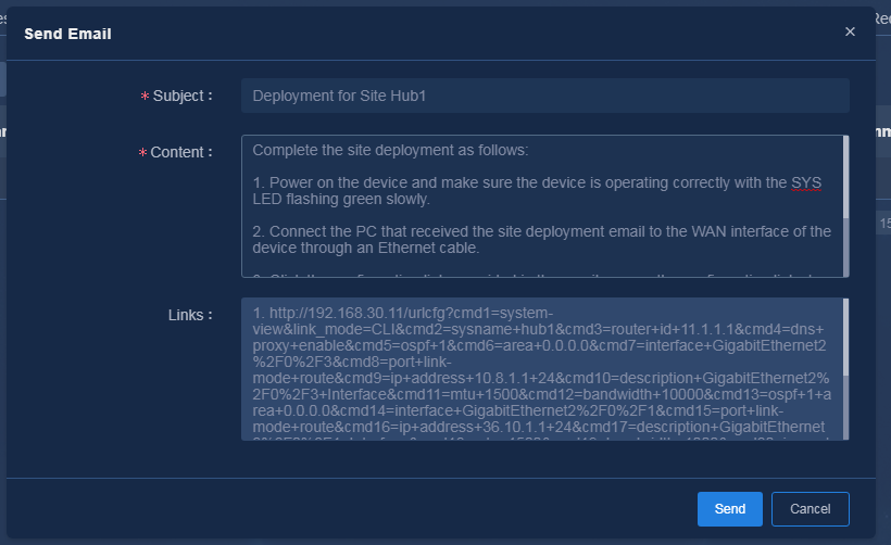
¡ Click
the ![]() icon in the Actions column for the device to be configured.
The mail to be sent is displayed, as shown in Figure 27. The
link information is encrypted. You can edit the mail contents as needed. Click OK
to send the mail. After the mail is successfully sent, the mail delivery state
changes to Delivered, as shown in Figure 28.
icon in the Actions column for the device to be configured.
The mail to be sent is displayed, as shown in Figure 27. The
link information is encrypted. You can edit the mail contents as needed. Click OK
to send the mail. After the mail is successfully sent, the mail delivery state
changes to Delivered, as shown in Figure 28.
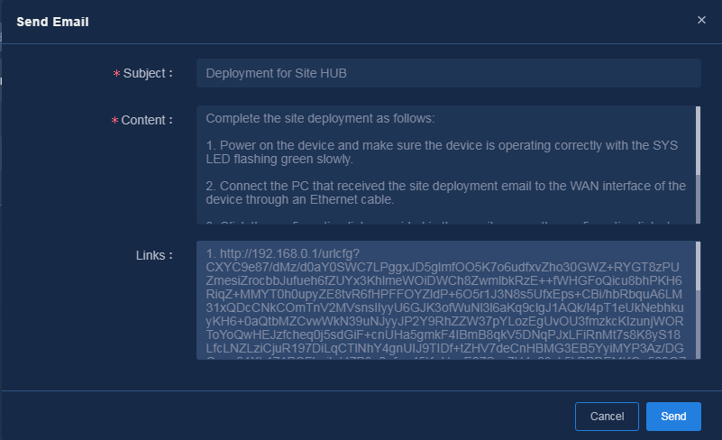
Figure 28 Sent the mail successfully
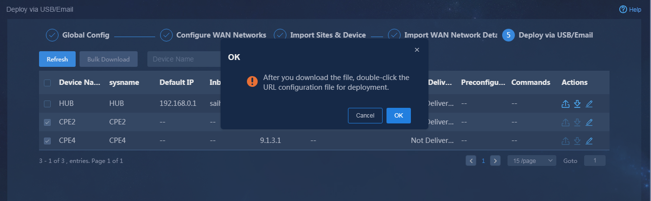
¡ Click
the ![]() icon in the Actions column for the device to be configured
to download the URL link (HTML file) used for deployment, as shown in Figure 29. You
can select multiple devices to download the URL links used for deployment in
bulk.
icon in the Actions column for the device to be configured
to download the URL link (HTML file) used for deployment, as shown in Figure 29. You
can select multiple devices to download the URL links used for deployment in
bulk.
Figure 29 Downloading the URL configuration file
Deploy devices via URL links in email
You can obtain the URL links for deployment via email or download the links, and use the links to perform deployment.
· Method 1: Log in to the corresponding mail account to receive the URL deployment mail, as shown in Figure 30. Mails support two types of URLs: long URLs and short URLs. You can use long URLs to deploy MSR routers in this solution.
Figure 30 A mail for deployment via URL
· Method 2: Download the URL file used for deployment, and use the URL file for deployment.
The detailed configuration procedure is as follows:
a. Make sure the computer and device used for deployment are reachable. Use a network cable to directly connect the first network port on the computer and that on the device. Configure an address that is on the same subnet as the device, for example, 192.168.0.100.
b. On the computer, click the URL link for deployment or double-click the URL deployment file to perform deployment.
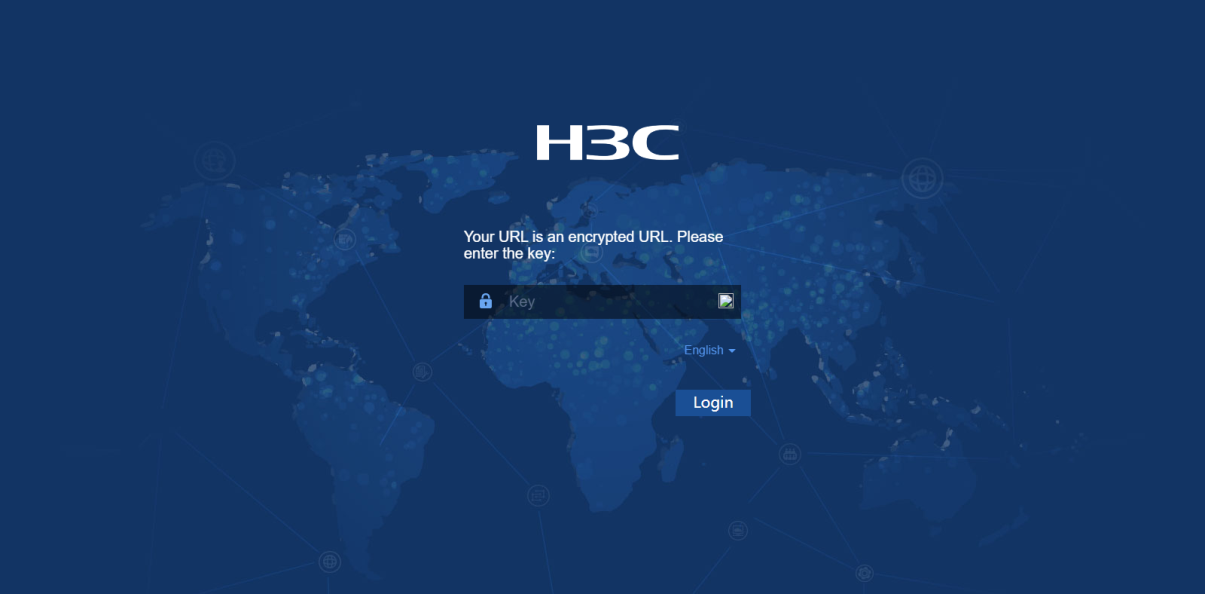
c. If the URL is encrypted, you will be prompted to enter the secret key, as shown in Figure 31. Enter the correct secret key. If no secret key is configured, skip this step.
Figure 31 Entering a secret key
a. Enter the default username and password (admin/admin) to perform authentication, as shown in Figure 32. The deployment authentication and login are completed.
Figure 32 URL deployment authentication and login
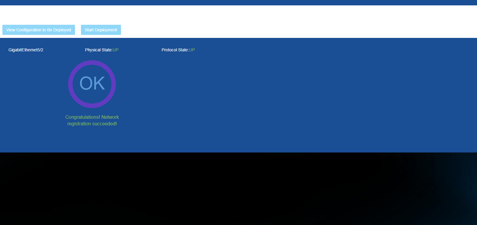
a. Access the deployment page, and click View Configuration to Be Deployed. You can see the configuration to be deployed, as shown in Figure 33. Click Start Deployment. Wait a period of time, and the final WebSocket registration result will be displayed, as shown in Figure 34.
Figure 33 Viewing the configuration deployed

Figure 34 Deployment via URL is finished
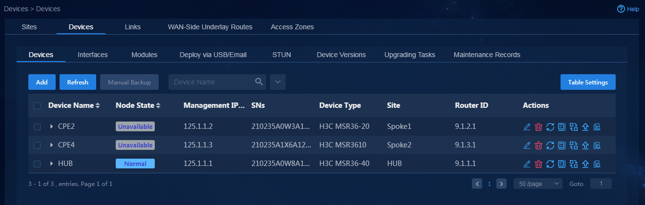
a. Wait a period of time after deployment via email is finished for a device. Then, navigate to the Automation > Branch Network > Physical Network > Devices > Devices page. You can see that the device has come online successfully, as shown in Figure 35.
Figure 35 Device deployed via URL has come online
Deploy devices via USB
Configure deployment via USB
1. Select the device for automatic deployment (Spoke2
in this example), and click the ![]() icon in the Actions
column for the device to deploy. Select Deploy via USB for the Deployment
Method, and enter the required parameters, as shown in Figure 36. Then,
click OK to save the configuration.
icon in the Actions
column for the device to deploy. Select Deploy via USB for the Deployment
Method, and enter the required parameters, as shown in Figure 36. Then,
click OK to save the configuration.
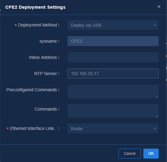
Parameters:
¡ Inbox Address: Configure the mail address that receives the configuration file for deployment via USB.
¡ NTP Server: Configure the NTP server address. You must configure this field for devices in the network. You can use the northbound IP address of the controller to synchronize time with the controller.
¡ Preconfigured Commands: The manually configured commands (for example, aggregate interface configuration commands) that take effect preferentially on the device. Press Enter after entering a command.
¡ Commands: The manually configured commands (for example, authentication configuration commands) that take effect at last on the device. Press Enter after entering a command.
¡ Ethernet Interface Link Mode: The default is route mode. The link mode of an Ethernet-type WAN interface is automatically switched to route mode. For VSR devices, you must use the default mode, and interfaces do not support the route mode.
2. Obtain the USB deployment file by using one of the following methods:
¡ Click
the ![]() icon in the Actions column for a device to download the USB
deployment file, as shown in Figure 37. The
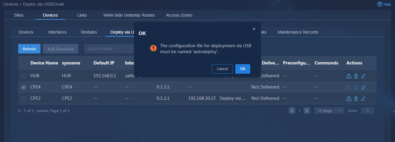
downloaded deployment file is named the same as the device. You must manually change the configuration file name to autodeploy.cfg.
icon in the Actions column for a device to download the USB
deployment file, as shown in Figure 37. The
downloaded deployment file is named the same as the device. You must manually change the configuration file name to autodeploy.cfg.
Figure 37 Downloading USB file
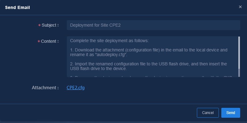
¡ Click
the ![]() icon in the Actions column for a device to send the USB
deployment file, as shown in Figure 38. The
sent deployment file is named the same as the device. You must manually change the configuration file name to autodeploy.cfg.
icon in the Actions column for a device to send the USB
deployment file, as shown in Figure 38. The
sent deployment file is named the same as the device. You must manually change the configuration file name to autodeploy.cfg.
Figure 38 Sending the USB deployment file
Use the USB configuration file for deployment
1. Copy the USB deployment file to the root directory of the USB flash drive. Insert the USB flash drive into the device, and reboot the device. The device will automatically start with the configuration file.
|
|
CAUTION: Make sure the USB flash drive uses the FAT32 file system. Insert the USB flash drive into the first USB interface of the device. |
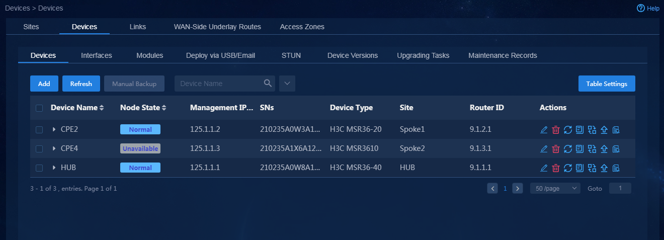
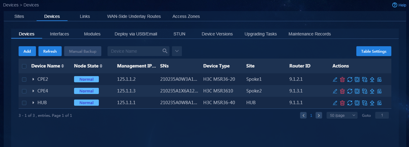
2. Wait a period of time after deployment via USB is finished for the device. Then, navigate to the Automation > Branch Network > Physical Network > Devices > Devices page. You can see that the device has come online successfully, as shown in Figure 39.
Figure 39 Device deployed via USB has come online
Manually deploy devices
You can select the manual deployment method. Manually configure the device interface and route settings, and make sure the device and controller can access each other.
1. The device actively sends WebSocket registration requests to the northbound address of the controller.
Take device Hub as an example. Manually add the registration-related settings.
[hub]router id 110.1.1.1
[hub]dns proxy enable
[hub]cloud-management backup-Server domain 90.2.1.2 port 19443
[hub]cloud-management Server domain 192.168.40.127 port 19443
[hub]cloud-management backup-Server domain 90.1.1.2 port 19443
[hub]cloud-management keepalive 60
[hub]cloud-management Server port 19443
Depending on how the device and controller are connected, you can use a private network address or public network address for registration.
2. Wait for a period of time after manual deployment. Then, navigate to the Automation > Branch Network > Physical Network > Devices > Devices page. You can see that the device has come online successfully, as shown in Figure 40.
Figure 40 Device deployed manually has come online
Plan branch networks
Log in to Unified Platform as the tenant service administrator (sdwan1).
Manage access zones
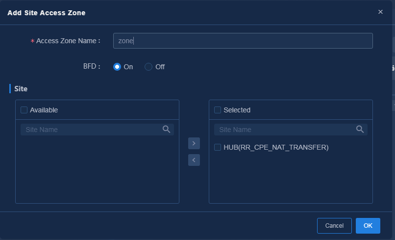
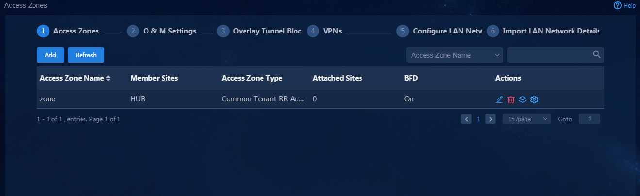
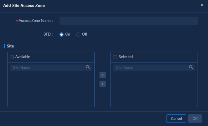
1. Navigate to the Guide > Branch Network Deployment > Plan Branch Networks > Access Zones page or navigate to the Automation > Physical Network > Access Zones > Access Zones page, and click Add to access the Add Site Access Zone page, as shown in Figure 41. When configuring an access zone, you must configure a site that functions as an RR and configure WAN network details for accessing the CPE site and RR site. You can add and edit access zones on the Automation > Physical Network > Access Zones page. After the access zone is configured, the page as shown in Figure 42 is displayed.
Figure 41 Configuring access zones
|
|
CAUTION: · You must select at least one RR site for an access zone. If the RR site deployment fails, CPEs cannot access the access zone. · For a network with a single RR, you must disable BFD. |
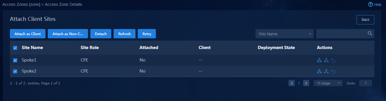
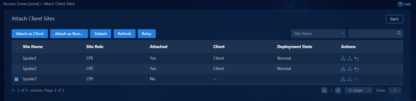
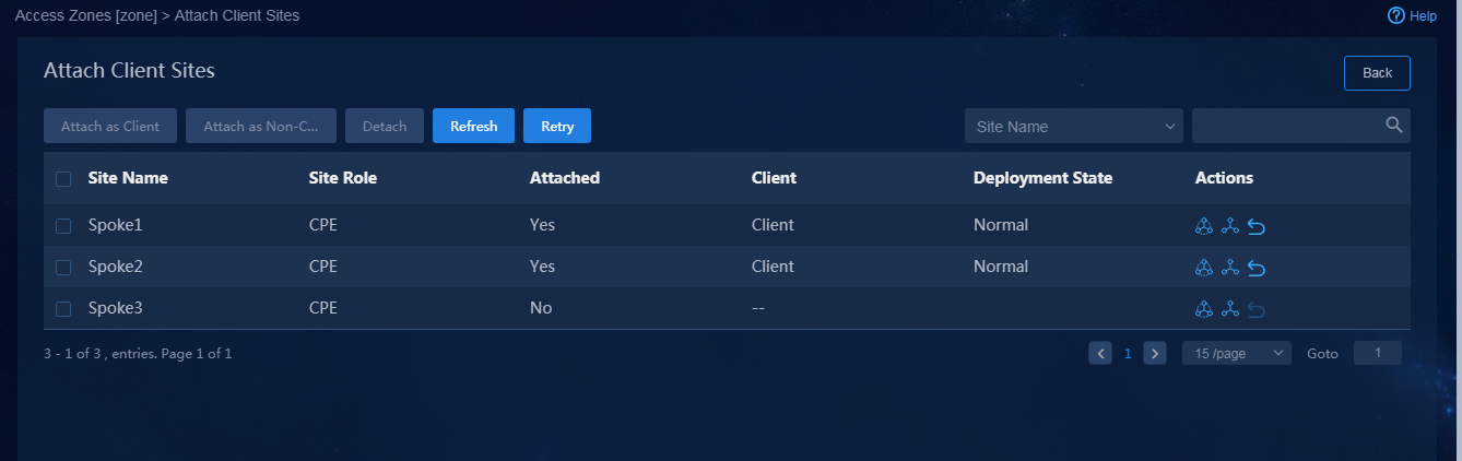
2. Click the Attach Client Sites icon ![]() in
the Actions column, as shown in Figure 43, and select
CPE for the sites to be attached. For example, select all the sites
except the site with a RR role, and attach a client site. If the site is
successfully deployed, the page as shown in Figure 44 is
displayed.
in
the Actions column, as shown in Figure 43, and select
CPE for the sites to be attached. For example, select all the sites
except the site with a RR role, and attach a client site. If the site is
successfully deployed, the page as shown in Figure 44 is
displayed.
Figure 43 Attaching client sites
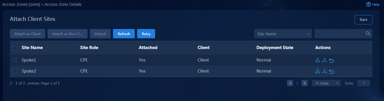
Figure 44 Sites attached successfully
|
|
CAUTION: · You must configure WAN details for the sites attached to access zones. · By default, the sites are attached as clients. If you select Attach as Non-Client, the network between sites might be blocked. Please use this feature with caution and contact Technical Support before use. |
Configure O&M settings
1. Navigate to the Automation > Plan Branch Network page, and configure related parameters, as shown in Figure 45 and Figure 46. After configuring parameters in an area, you must click OK to save the configuration.
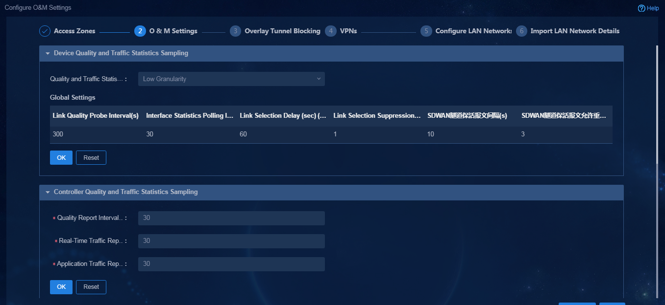
Parameters:
¡ Device Quality and Traffic Statistics Sampling: According to the network scale, you can select a granularity as needed. Different granularities correspond to different global parameters. You can also select self-defined O&M parameters. The O&M parameters will be deployed to devices. Based on these O&M parameters, the device performs detection and path selection. The O&M parameters are described as follows:
- Link Quality Probe Interval(s): Intervals at which link quality probes are performed for the SDWAN tunnel.
- Interface Statistics Polling Interval: Interval at which interface traffic statistics are collected, in seconds.
- Link Selection Delay: Period of time (in seconds) to be delayed for the RIR to perform a link selection when the link quality or bandwidth does not meet the requirements to avoid frequent link selections.
- Link Selection Suppression Interval: Time interval (in seconds) to be waited for the RIR to perform a link switchback. This parameter is used to avoid frequent switchbacks.
- SDWAN Tunnel Keepalive Interval: Time interval at which the SDWAN tunnel sends keepalive request packets. The value is in the range of 1 to 32767, in seconds.
- SDWAN Tunnel Keepalive Retries: The maximum number of retries allowed if the SDWAN tunnel does not receive a keepalive response packet. The value is in the range of 1 to 255.
¡ Controller Quality and Traffic Statistics Sampling: Time-related settings for the controller to collect device information.
- Quality Report Interval: Interval at which the controller reports the link quality report, in milliseconds.
- Real-Time Traffic Report Interval: Interval at which the device reports real-time traffic packets, in milliseconds.
- Application Traffic Report Interval: Interval at which the device reports application traffic packets, in milliseconds.
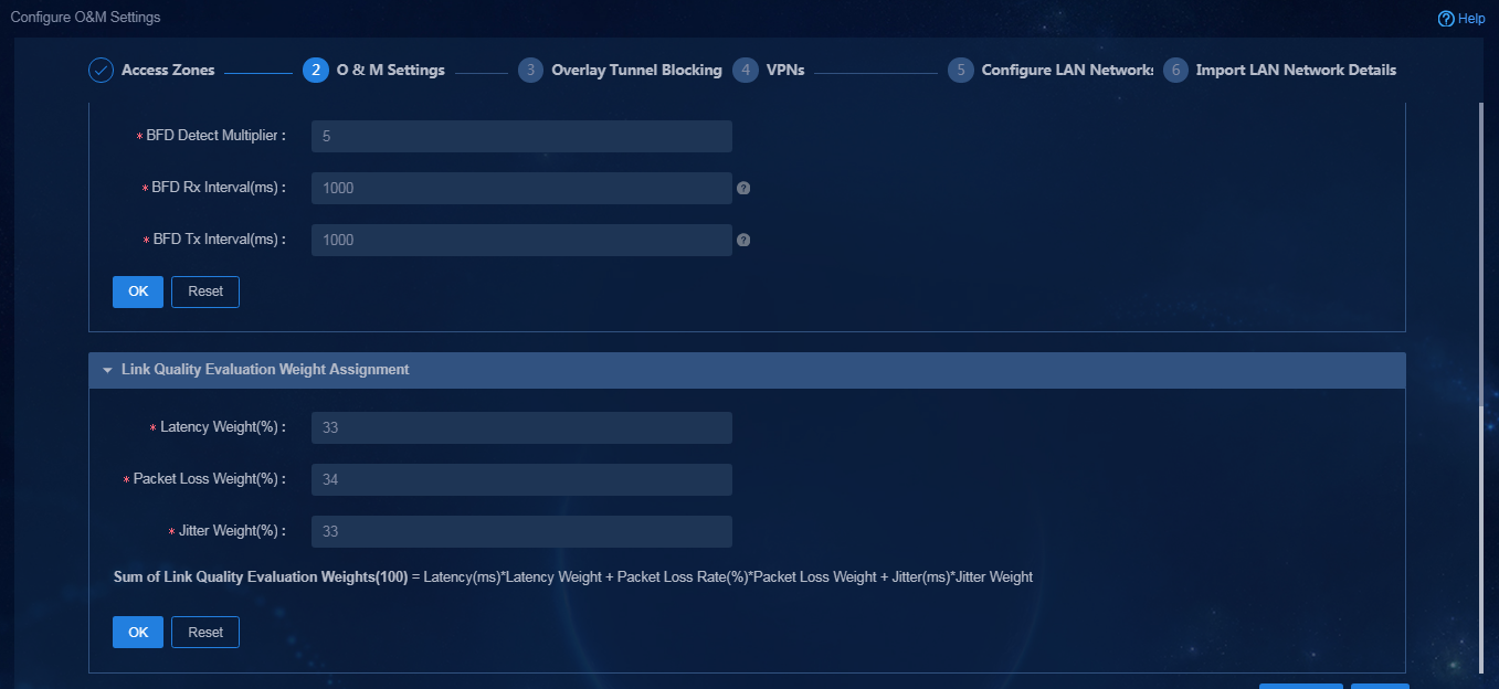
¡ Global BFD Settings: BFD settings that the controller deploys to the routing protocol and time parameters to deploy the BFD settings.
- BFD Detect Multiplier: BFD detection time multiplier.
- BFD Rx Interval: Minimum interval for receiving BFD control packets, in milliseconds.
- BFD Tx Interval: Minimum interval for sending BFD control packets, in milliseconds.
¡ Link Quality Evaluation Weight Assignment: When the controller evaluates the link quality, the link quality evaluation value (100)=Latency evaluation value*latency weight + packet loss evaluation value*packet loss ratio weight + jitter evaluation value*jitter weight. The quality evaluation algorithm (take latency as an example) is as follows: (Maximum latency value - current latency value)/Maximum latency value. The system-defined maximum latency value is 1600 ms, the maximum packet loss ratio is 100%, and the maximum jitter value is 1600 ms.
- Latency Weight (%): Weight of latency in link quality evaluation.
- Packet Loss Weight (%): Weight of packet loss in link quality evaluation.
- Jitter Weight (%): Weight of jitter in link quality evaluation.
2. After the configuration guide is completed, view the corresponding O&M parameters on the Automation > Branch Network > Parameter Settings > O & M Settings page. On this page, you can also edit O&M settings.
|
|
CAUTION: If you need to enable BFD for BGP neighbors, make sure the BFD detection time and number of detections are greater than those for tunnel keepalive packets. |
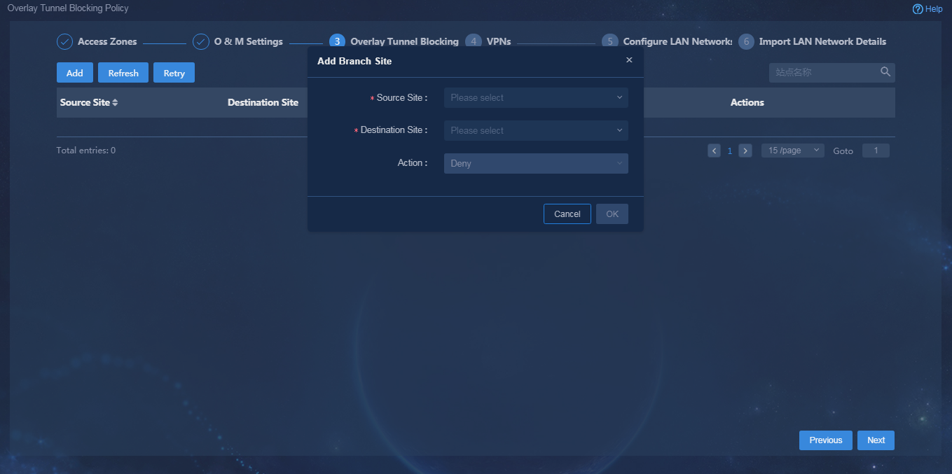
Configure an overlay tunnel blocking policy
This feature enables you to view, add, delete, and edit an inter-site tunnel setup model. In initial configuration, you must configure an inter-site tunnel setup model for connection between the two sites. When a VPN is created, an inter-site VPN access model will be established based on the inter-site tunnel setup model, enabling flexible topology.
Navigate to the Guide > Branch Network Deployment > Plan Branch Network > Overlay Tunnel Blocking Policy page, and click Add, as shown in Figure 47. Select a source site and a destination site to block the tunnel so that a TTE association cannot be established between the two sites.
Figure 47 Adding an overlay tunnel blocking policy
|
|
CAUTION: An inter-site blocking policy can only be configured between CPEs. After configuration, the network between CPEs will be blocked. Please contact Technical Support first and configure it with caution. |
Manage VPNs
The service traffic of users is isolated by using bound VPNs. At least one VPN needs to be configured. In this example, vpn1 and vpn2 are configured.
1. Navigate to the Guide > Branch Network Deployment > Plan Branch Network > VPNs page or navigate to the Automation > Branch Network > Tenant Network > VPNs page, and click Add. On the Add VPN Instance page, configure related parameters as shown in Figure 48, and then click OK to save the configuration.
Figure 48 Adding a VPN instance
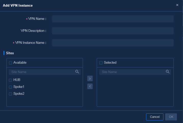
Parameters:
¡ VPN Name: VPN name saved on the controller, for example, vpn1.
¡ VPN Instance Name: VPN instance configuration deployed to devices, for example, vpn11.
¡ Sites: Specify the sites where the VPN traffic is forwarded. In this example, all the sites are selected.
2. Click the Add icon in the Actions column to access the Create Area Topology page. Create a HUB-SPOKE mode area topology, as shown in Figure 49, and then click OK to save the configuration.
Figure 49 Creating a HUB-SPOKE area topology
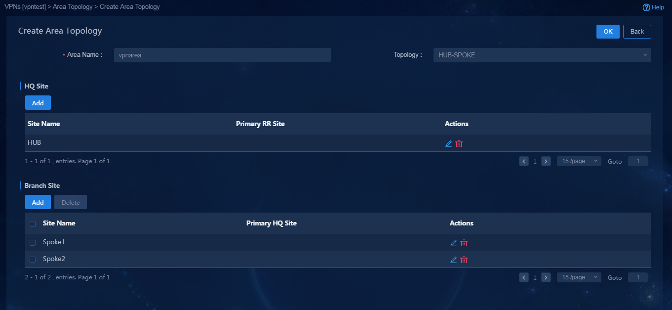
Parameters:
¡ Configure the following parameters if the topology mode is HUB-SPOKE.
- HQ Site: Configure the hub device as the HQ site.
- Branch Site: Configure the SPOKE device as the branch site.
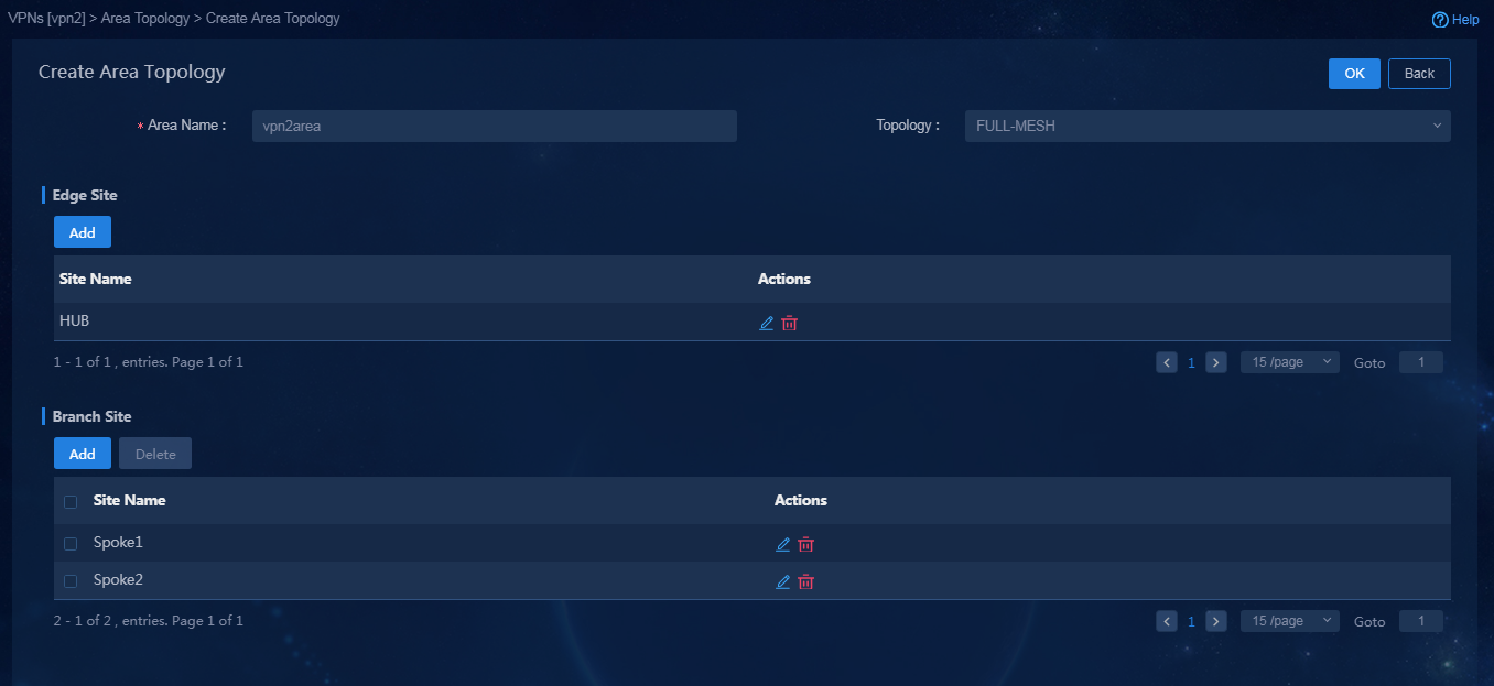
¡ Configure the following parameters if the topology mode is FULL-MESH. The default networking of the controller is full-mesh networking. If the full-mesh mode is configured for all sites, you do no need to configure any site for the area topology.
- Edge Site: The traffic ingress and egress of the area topology if the traffic between the branch site in this area topology and that in other area topologies is forwarded through the edge site.
- Branch Site: The networking model of the branch sites is a full-mesh model.
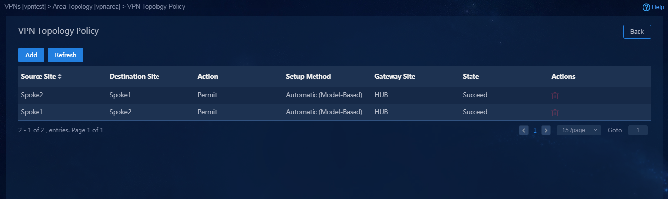
3. Click the ![]() icon in the Actions
column to access the Area
Topology page. Click the
icon in the Actions
column to access the Area
Topology page. Click the ![]() icon in the Actions column to access the VPN Topology Policy page to verify that VPN topology
policies are successfully deployed, as shown in Figure 50.
icon in the Actions column to access the VPN Topology Policy page to verify that VPN topology
policies are successfully deployed, as shown in Figure 50.
Figure 50 VPN topology policies
4. Create vpn2, and configure the topology mode as FULL-MESH, as shown in Figure 51. The default networking of the controller is full-mesh networking. If the full-mesh mode is configured for all sites, you do no need to configure any site for the area topology.
Figure 51 Creating the FULL-MESH area topology
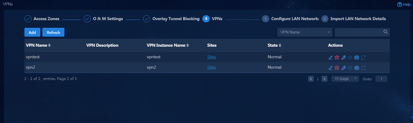
5. Click OK. The VPNs are successfully created, as shown in Figure 52.
Configure LAN networks
1. Navigate to the Guide > Branch Network Deployment > Plan Branch Networks > Configure LAN Networks page, and click Add to add LAN networks according to the actual network requirements, as shown in Figure 53. In this example, subinterfaces are used to create multiple LAN networks with different VLAN IDs.
Figure 53 Configuring LAN networks
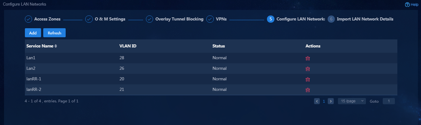
Configuration description:
¡ LanRR-1: Corresponds to VLAN ID 120 and terminates VLAN 20. Configure the LAN interface of the HUB-SPOKE area topology for vpn1. The configuration of the branch device is the same.
¡ LanRR-2: Corresponds to VLAN ID 21 and terminates VLAN 21. Configure the LAN interface of the FULL-MESH area topology for vpn2. The configuration of the branch device is the same.
¡ DefaultLan (system default): After you manually configure LAN interfaces, you can configure DefaultLan to specify LAN interfaces on devices. Typically, it is used for reforming an existing network. If you use DefaultLan, you must publish routes in the routing module.
2. Click Next to access the Import LAN Network Details page.
Import LAN network details
1. On the page for importing LAN network details, click Download Template to download a template and follow the instructions to enter LAN network detail information in the template, as shown in Figure 54.
Figure 54 Guidelines for importing LAN network details
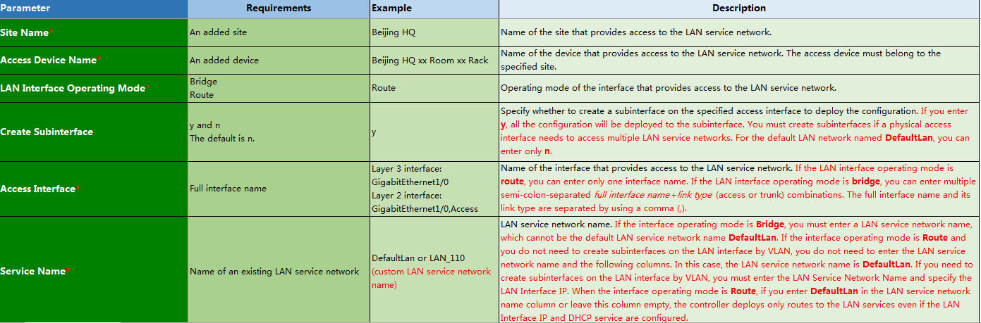
Parameters:
¡ LAN Interface Operating Mode: Select the bridge mode for a routing switch. Typically, select the route mode.
¡ Create Subinterface: In the route mode, you must specify whether to create a subinterface on the specified access interface on the access device to deploy the configuration. On the subinterface, use the VLAN ID configured in the LAN network to configure VLAN termination. In this example, you must create subinterfaces for LAN-side interfaces.
¡ Access Interface: Name of the interface that provides access to the LAN service network.
¡ Service Name: Name of an existing LAN service network.
¡ LAN Interface IP: LAN interface IP address deployed by the controller.
¡ VPN Name: Name of the VPN instance bound to LAN interface. In the EVPN solution, all the LAN interfaces must be bound to VPN instances.
¡ Enable DHCP: Specify whether to enable the IPV4 DHCP service on the LAN interface.
¡ Enable DHCPv6: Specify whether to enable the IPV6 DHCPv6 service.
¡ Enable VRRP: Specify whether to enable VRRP.
¡ MTU: MTU of the interface. By default, the interface has an MTU. As a best practice, do not set this field.
¡ TCP MSS: Maximum TCP packet fragment size. You must configure this field for LAN services deployed by the controller. As a best practice, set the TCP MSS to 1280.
¡ Auto Import LAN-side Routes: Configure the controller to import routes of the LAN interfaces through routing policies. As a best practice, select Yes.
After the LAN network details are imported, the page is as shown in Figure 55.
Figure 55 Importing LAN network details
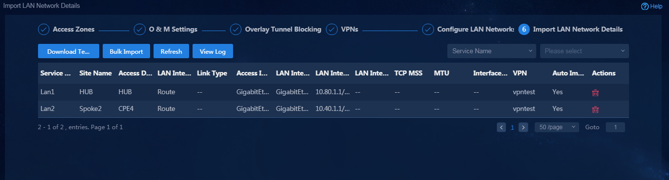
|
|
CAUTION: When importing LAN network details, you must set TCP MSS to 1280. |
Add devices
After the configuration guide is completed, you can manually add devices.
1. Log in to Unified Platform as the tenant service administrator (sdwan1). Navigate to the Automation > Branch Network > Physical Network > Devices > Devices page, as shown in Figure 56. On this page, you can view the device list. Before adding devices, make sure the BGP AS number and management interface number in global configuration have been configured.
2. Add devices by using either of the following methods:
¡ Import new devices through a template. For how to configure parameters in the template, see "Import sites and devices."
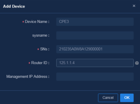
¡ Click Add. On the page that opens, you can manually add a device, as shown in Figure 57.
Figure 57 Manually adding a device
Add sites
After manually adding a device, you must add a site and bind the device to the site.
1. Log in to Unified Platform as the tenant service administrator (sdwan1). Navigate to the Automation > Branch Network > Physical Network > Sites > Sites page, as shown in Figure 58. On this page, you can view the site list.
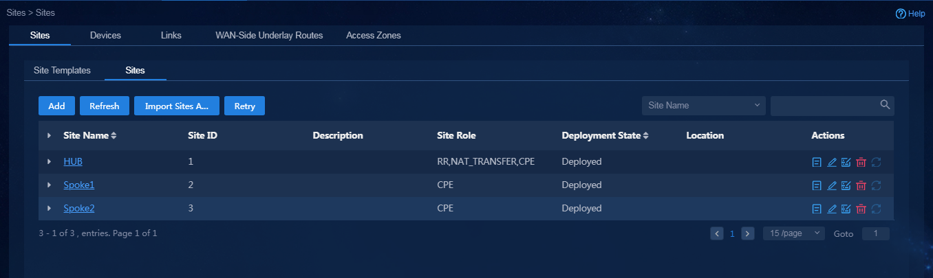
2. Add sites by using either of the following methods:
¡ Import new sites and bind devices to sites through a template. For how to configure parameters in the template, see "Import sites and devices."
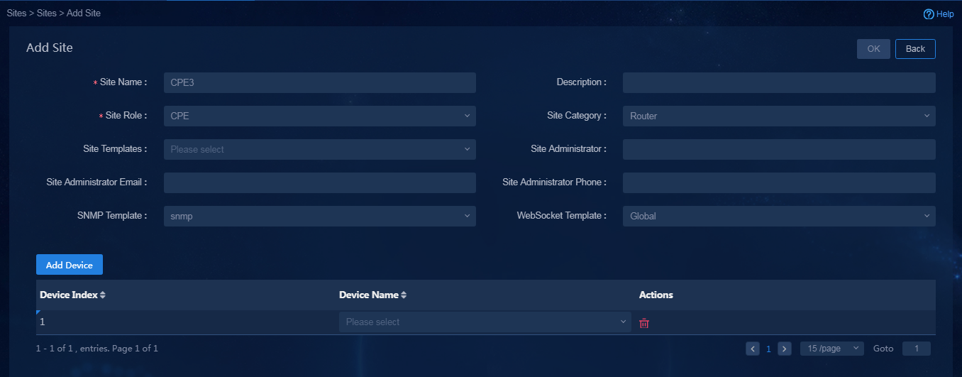
¡ Click Add. On the page that opens, you can manually add a site. Take site Site6 as an example, as shown in Figure 59.
Figure 59 Manually adding a site
(Optional) Configure STUN
After the configuration guide is completed, you can add a STUN server.
1. Log in to Unified Platform as the tenant service administrator (sdwan1). Navigate to the Automation > Branch Network > Physical Network > Devices > STUN page, as shown in Figure 60. On this page, you can view the STUN list.

2. Click Add to manually add a STUN server, as shown in Figure 61.
Add WAN networks and WAN network details
After manually adding devices and sites, you must configure WAN network and WAN network details for devices.
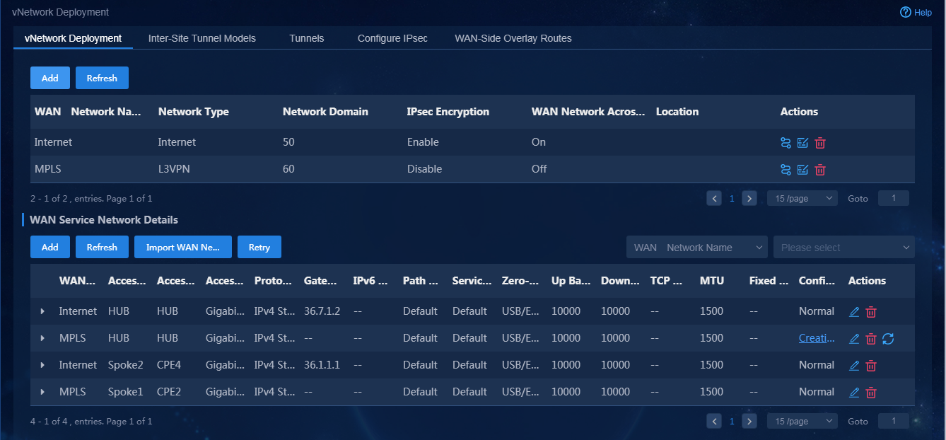
1. Log in to Unified Platform as the tenant service administrator (sdwan1). Navigate to the Automation > Branch Network > Virtual Network > vNetwork Deployment page, as shown in Figure 62. On this page, you can view the WAN networks and WAN network details.
Figure 62 WAN networks and WAN network details
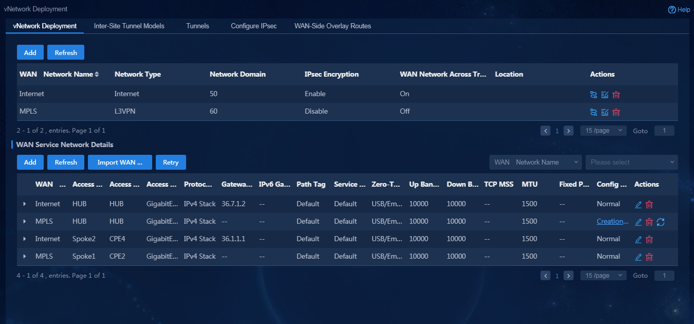
2. Click Add. On the page that opens, you can add a new WAN network. For how to add a new WAN network, see "Configure WAN Networks."
3. Add WAN network details by using either of the following methods:
¡ For newly added devices, you can import WAN network details through a template. For how to configure parameters in the template, see "Import WAN network details."
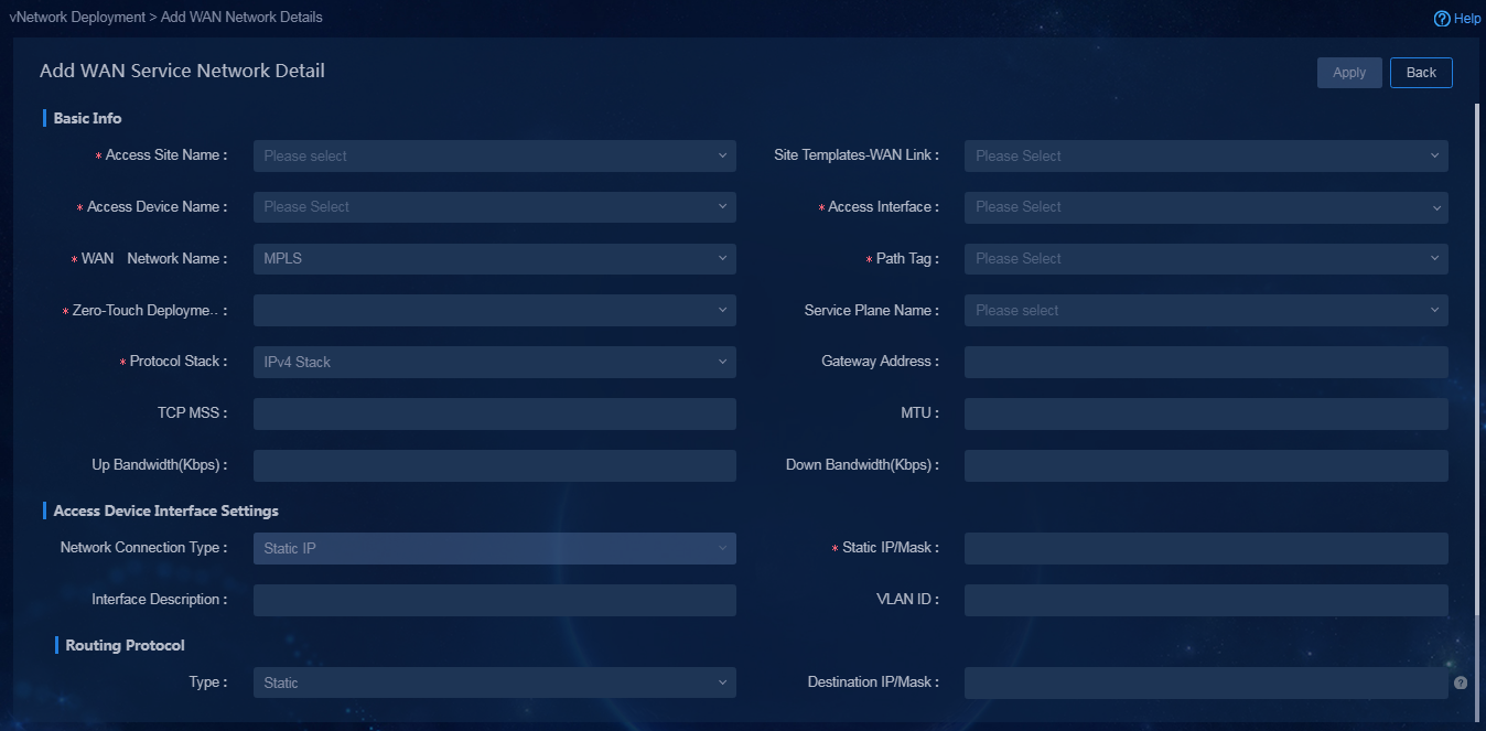
¡ Click Add in the WAN Service Network Details area. You can manually add a WAN service network detail. In this example, add a new WAN network detail for the Internet interface of device Hub, as shown in Figure 63.
Figure 63 Manually adding a WAN network detail
Deploy devices via USB/email or manually deploy devices
After importing WAN network details, you can select to deploy via USB/email or manually deploy.
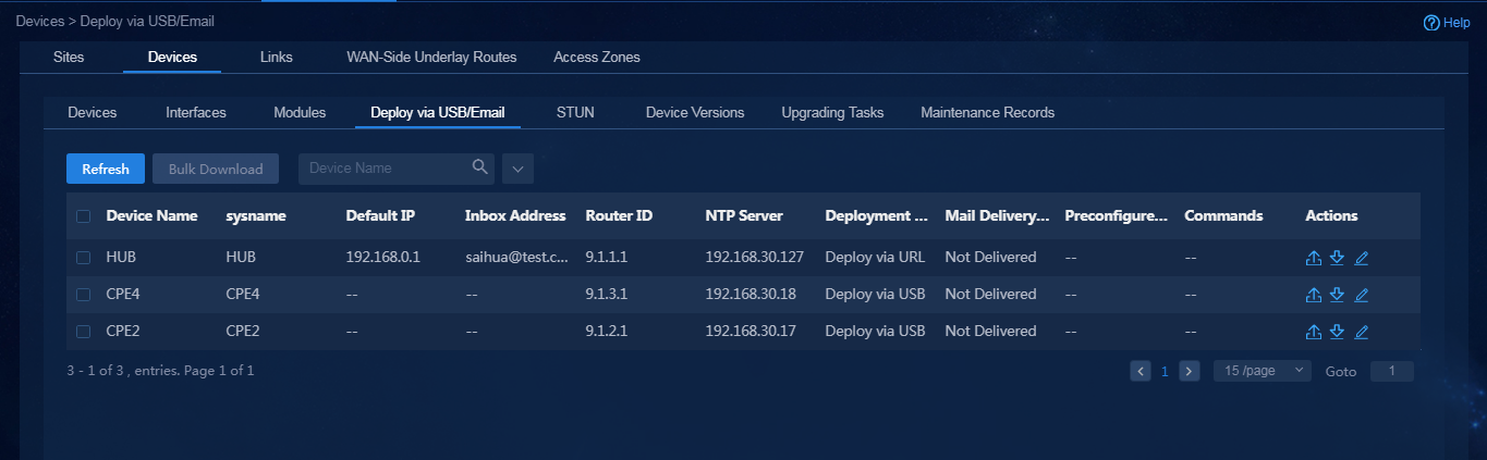
· To perform deployment via USB/email, log in to Unified Platform as the tenant service administrator (sdwan1). Navigate to the Automation > Branch Network > Physical Network > Devices > Deploy via USB/Email page, as shown in Figure 64. For more information, see "Deploy devices via USB/email."
Figure 64 Deployment via USB flash drive or email
· For how to perform manual deployment, see "Manually deploy devices."
Configure access zones
After the configuration guide is completed, you can create access zones or add new sites to the created access zones.
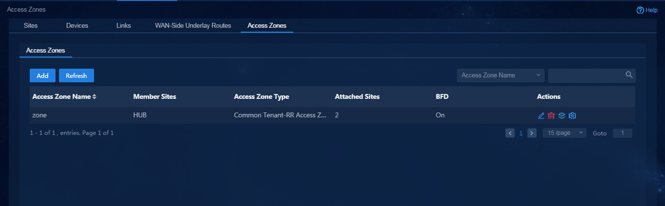
1. Log in to Unified Platform as the tenant service administrator (sdwan1). Navigate to the Automation > Branch Network > Physical Network > Access Zones > Access Zones page, as shown in Figure 65. On this page, you can view information about access zones.
Figure 65 Managing access zones
2. Click Add to access the Add Site Access Zone page, as shown in Figure 66. For more information, see "Manage access zones."
Figure 66 Adding site access zones
|
|
CAUTION: · You must select at least one RR site for an access zone. If the RR site deployment fails, CPEs cannot access the access zone. · For a network with a single RR, you must disable BFD. |
3. If the newly added site has an access zone,
click the ![]() icon in the Actions column, and select Client, as
shown in Figure 67. For more information, see "Manage access zones."
icon in the Actions column, and select Client, as
shown in Figure 67. For more information, see "Manage access zones."
|
|
CAUTION: · You must configure WAN details for the sites attached to access zones. · By default, the sites are attached as clients. If you select Attach as Non-Client, the network between sites might be blocked. Please use this feature with caution and contact Technical Support before use. |
Configure the VPN
You must bind service traffic to a VPN. The traffic forwarding model is determined by the VPN topology.
1. Log in to Unified Platform as the tenant service administrator (sdwan1). Navigate to the Automation > Branch Network > Tenant Network > VPNs page, as shown in Figure 68. On this page, you can view VPN information.
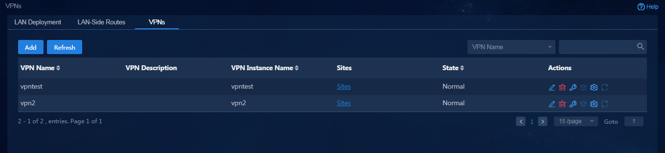
2. Click Add. On the page that opens, you can add a new VPN. For how to add a new VPN, see "Manage VPNs."
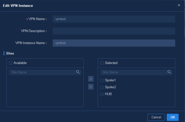
3. If a newly added
site belongs to an existing VPN, select the VPN, and click the ![]() icon
in the Actions column. On the page that opens, bind the newly added site
to the VPN, as shown in Figure 69. Click
OK to save the configuration.
icon
in the Actions column. On the page that opens, bind the newly added site
to the VPN, as shown in Figure 69. Click
OK to save the configuration.
Figure 69 Editing VPN information
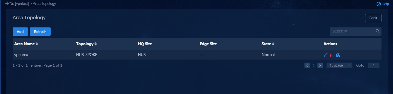
4. After a site is bound to a VPN, you must configure the area topology according to the requirements of the traffic forwarding model. Click the Area Topology icon in the Actions column to view the configured topology, as shown in Figure 70.
Figure 70 Viewing the VPN area topology
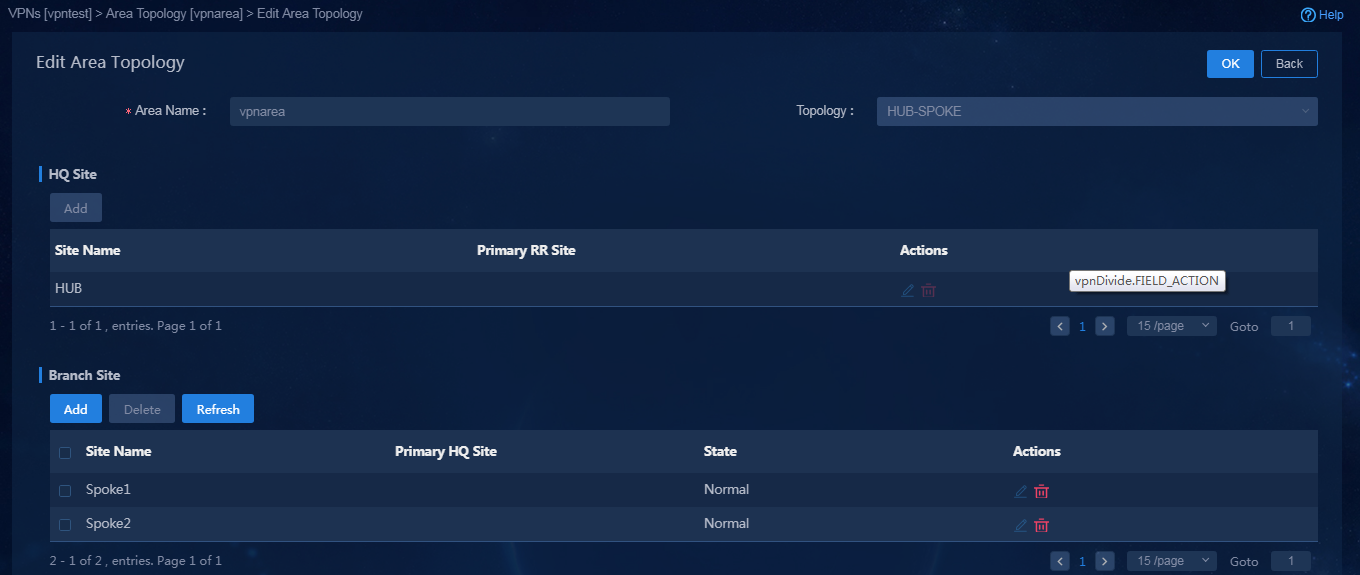
5. To add or edit a site on the topology, click
the Edit icon ![]() in the Actions column, as shown in Figure 71.
in the Actions column, as shown in Figure 71.
Figure 71 Editing an area topology
Add LAN networks and LAN network details
1. Log in to Unified Platform as the tenant service administrator (sdwan1). Navigate to the Automation > Branch Network > Tenant Network > LAN Deployment page, as shown in Figure 72. On this page, you can view the LAN networks and LAN network details.
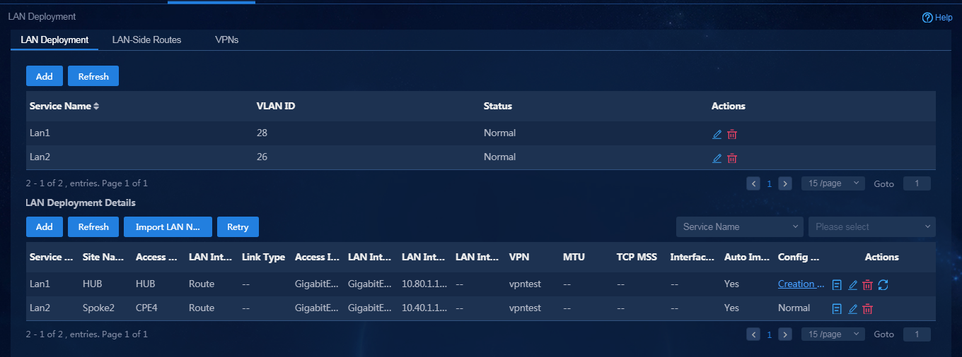
2. Click Add. On the page that opens, add a new LAN network. For how to add a new LAN network, see "Configure LAN networks."
3. Add LAN network details by using either of the following methods:
¡ For newly added devices, import LAN network details through a template. For how to configure parameters in the template, see "Import LAN network details."
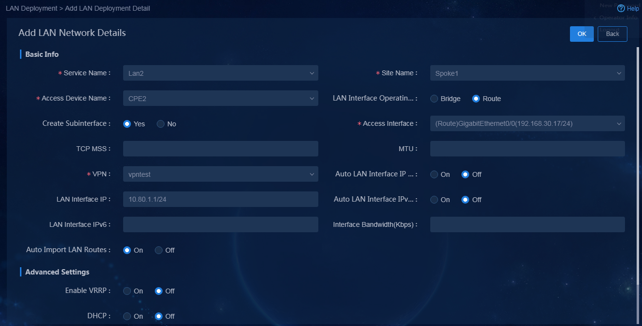
¡ Click Add in the LAN Deployment Details area. You can manually add a LAN service network detail. In this example, add a new LAN network detail for the vpn1 interface of device Hub, as shown in Figure 73.
Figure 73 Manually adding a LAN network detail
|
|
CAUTION: When adding LAN network details, you must set TCP MSS to 1280. |
Optimize device settings
Switch the working mode
The memory of an MSR device is small. You can switch the device to SD-WAN mode to optimize memory usage. After switching the working mode for an MSR device, you must reboot the device. All MSR devices can be switched to SD-SWAN mode. For an SR66 device, you do not need to switch it to SD-WAN mode.
Execute the following commands to switch the working mode:
<Spoke1>system-view
System View: return to User View with Ctrl+Z.
[Spoke1]system-working-mode sd-wan
Do you want to change the system working mode? [Y/N]:y
The system working mode is changed, please save the configuration and reboot the system to make it effective.
[Spoke1]quit
<Spoke1>reboot
|
|
CAUTION: After switching the working mode to SD-WAN for a device, you cannot perform deployment via URL. To use deployment via URL, first perform deployment and then switch the working mode. |
Deploy configuration optimization commands
In addition to configuration commands automatically deployed by the controller, you must deploy some optimization commands to devices. You can deploy these commands in bulk from the controller or manually log in to the devices and add these commands.
· In the following section, use the controller to bulk deploy configuration commands.
Log in to Unified Platform as the tenant service administrator (sdwan1). Navigate to the Automation > Assurance > Bulk-Configure Devices page. Select the devices to be configured, and enter the commands as needed. In bulk device configuration, a device automatically enters the system view, so you do not need to enter the system-view command.
· Configurations that must be manually deployed:
a. For an IRF fabric or a modular device, you must configure the service slot/service chassis x slot x command on the tunnel interface to specify the device's module for forwarding traffic.
interface Tunnel1 mode sdwan udp
service chassis 1 slot 3
b. As a best practice, disable the IPsec anti-replay check if IPsec encryption is deployed,.
undo ipsec anti-replay check
c. The TCP MSS function will trigger session setup. Setting the tcp-est aging time to 3600s will cause many sessions to be held. In this case, change the tcp-est aging time to 300s.
session aging-time state tcp-est 300
Query device and link state
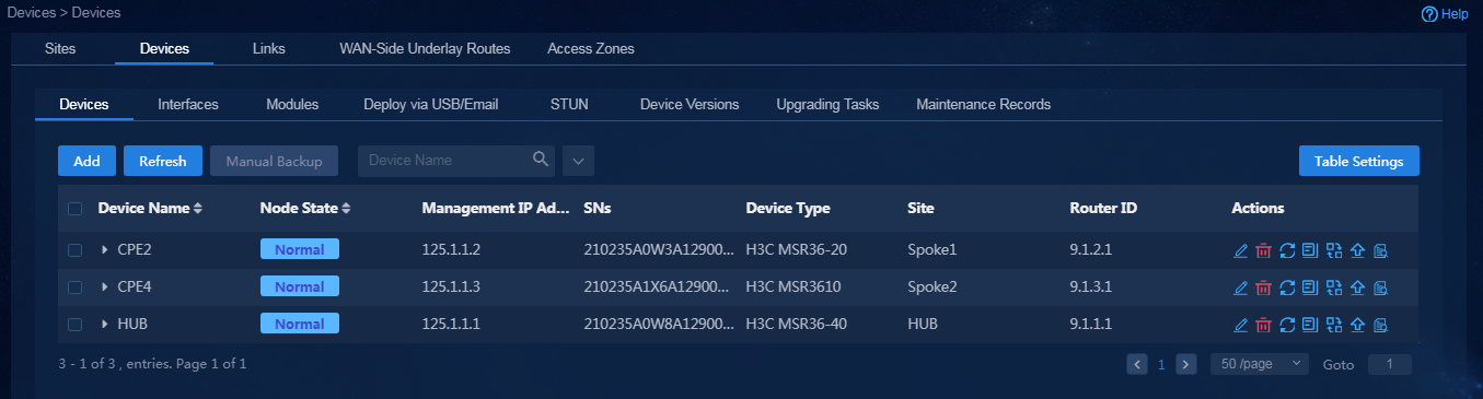
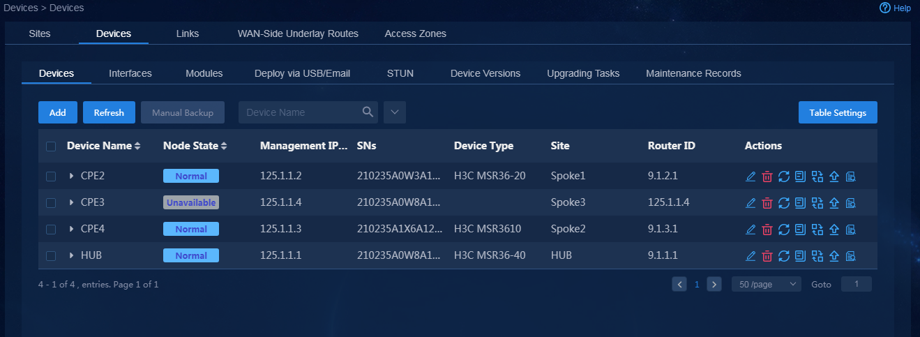
1. Log in to Unified Platform as the tenant service administrator (sdwan1). Navigate to the Automation > Branch Network > Physical Network > Devices > Devices page. On this page, you can view device information, for example, node state, serial number, and device type, as shown in Figure 74. If you switch to the Interfaces and Device Versions tabs, you can view the corresponding device information.
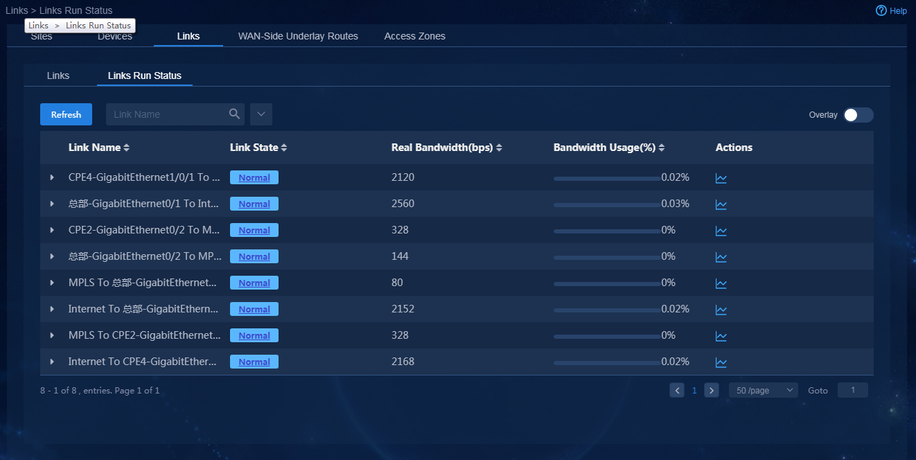
2. Navigate to the Automation > Branch
Network > Physical Network > Links > Links
page. You can view information
about all links. Additionally, you can enable Overlay to display overlay
link information. Click the Links Run Status tab. On this tab, you can view the real-time running state of each
link, as shown in Figure 75. Click
the ![]() icon in the Actions column for a link to view history link
information. Alternatively, you
can view information about
overlay links.
icon in the Actions column for a link to view history link
information. Alternatively, you
can view information about
overlay links.
Figure 75 Links running status
Check WAN service deployment state
After WAN service deployment is completed, log in to Unified Platform as the tenant service administrator (sdwan1), and perform the following tasks to confirm the WAN service deployment state.
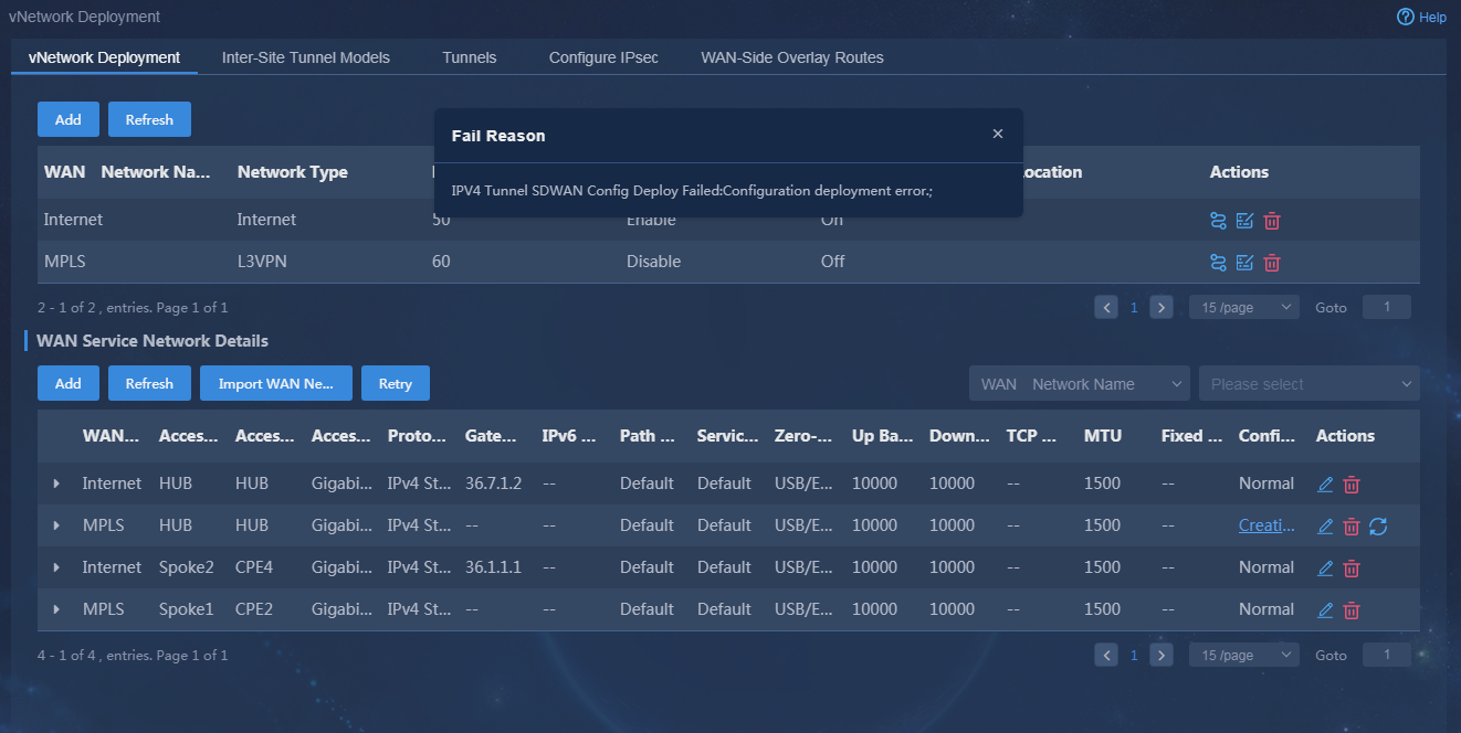
1. Navigate to the Automation > Branch Network > Virtual Network > vNetwork Deployment page. On the WAN Service Network Details page, you can see the WAN service network deployment state. If the state of a WAN service network detail is abnormal, click the state to view the corresponding reason, as shown in Figure 76. After you repair it according to the error reason, click Retry to redeploy the configuration.
Figure 76 Querying WAN service configuration state
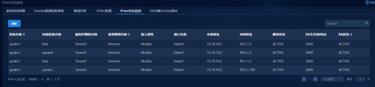
2. If IPsec tunnels are deployed (IPsec encryption is enabled for Internet or L3VPNs), you can view the IPsec tunnel state. Navigate to the Automation > Branch Network > Virtual Network > IPsec State Monitoring page. You can view the IPsec tunnel state, as shown in Figure 77. If an IPsec tunnel fails, the IPsec SA information is not displayed.
Figure 77 Querying IPsec states
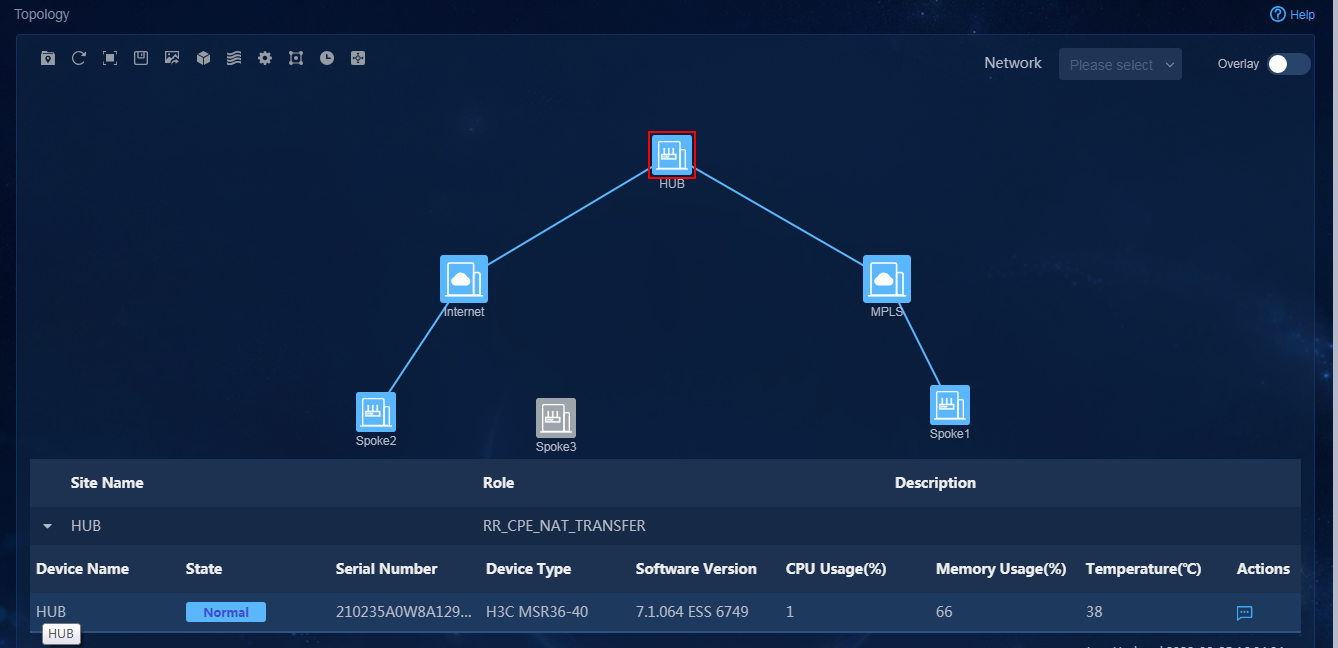
3. Navigate to the Monitor > Topology > Branch Topology page. On this page, you can view topology information, including underlay and overlay topology, as shown in Figure 78.
4. Navigate to the Automation > Branch Network > Physical Network > Access Zones page, and verify the deployment state of access zones, as shown in Figure 79.
Figure 79 Access zone deployment state
Check LAN service deployment state
After LAN deployment is completed, log in to Unified Platform as the tenant service administrator (sdwan1). Navigate to the Automation > Branch Network > Tenant Network > LAN Deployment page. On this page, you can view the LAN service configuration state. If the state of a LAN service network is abnormal, click the state to view the corresponding reason, as shown in Figure 80. After you repair it according to the error reason, click Retry to redeploy the configuration.
Figure 80 Querying LAN service configuration state
WAN service deployment
Configuration workflow
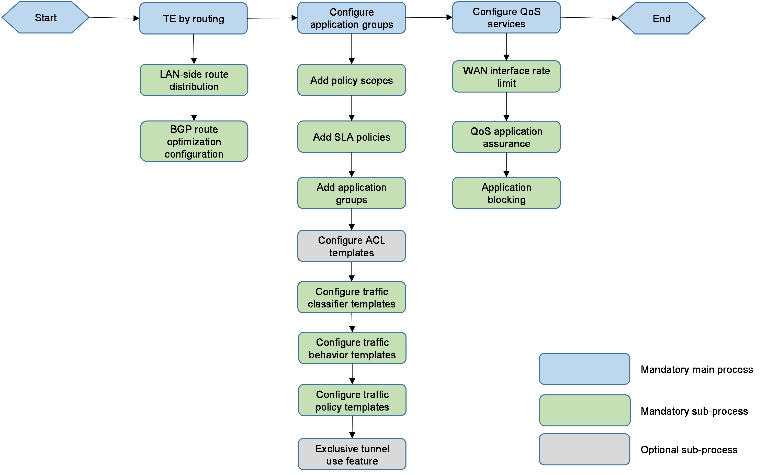
WAN service deployment includes deploying application TE settings and the related QoS services. The configuration workflow is shown in Figure 81.
Figure 81 Flowchart of configuring process
TE by routing
A service network must be bound to a VPN. As a best practice, select Auto Import LAN-side Routes when you create a LAN network. Alternatively, you can configure route advertisement through the controller. For more information, see "Configure TE by routing."
· Intra-VPN TE by routing: For information about the routes to be imported, see Table 6.
Table 6 TE by routing requirements
|
VPN |
Device |
IPv4 route segment |
IPv6 route segment |
|
VPN1 (HUB-SPOKE) |
Hub |
33.1.1.1/24 |
3301::1/64 |
|
spoke1 |
33.2.1.1/24 |
|
|
|
spoke2 |
33.3.1.1/24 |
|
|
|
spoke3 |
33.4.1.1/24 |
|
|
|
spoke4 |
33.5.1.1/24 |
3305::1/64 |
|
|
VPN2 (FULL-MESH) |
Hub |
35.1.1.1/24 |
3501::1/64 |
|
spoke1 |
35.2.1.1/24 |
|
|
|
spoke2 |
35.3.1.1/24 |
|
|
|
spoke3 |
35.4.1.1/24 |
|
|
|
spoke4 |
35.5.1.1/24 |
3505::1/64 |
· To ensure service traffic intercommunication, you must configure underlay TE and route optimization. If the LAN-side headquarters devices use dynamic routing protocols (for example, OSPF) to communicate with the intranet, you must redistribute BGP routes to OSPF. If the basic routes for the headquarters devices are manually configured, the manually configured route settings require to be issued manually. If a routing protocol is configured by the controller, you can redistribute the BGP routes to OSPF through the route module on the controller page.
Deploy TE services
Application TE service includes defining application groups and TE policies and deploying TE applications. For how to deploy them, see "Application group traffic scheduling and visualization." For the related requirements, see Table 7.
Table 7 Service TE requirements
|
Application name |
VPN |
Policy scope |
Application definition |
Application policy |
|
App1 (FLOW ID: 100) |
VPN1 |
· Name: H-S · Site: Site1, Site2 |
· Name: app1-acl · Quintuple application definition: TCP protocol, source or destination address matching 33.1.1.100 |
· Name: SLA1 · SLA level: Network · Priority policy (priority order): Layer 3 leased lines > Internet (Mobile) > Internet (Unicom) |
|
App2 (FLOW ID: 200) |
· Name: app2-acl · Quintuple application definition: TCP protocol, source or destination address matching 33.1.1.200 |
|||
|
App3 (FLOW ID: 101) |
· Name: S-S · Site: Site1, Site2, Site4 |
· Name: app3-acl · Quintuple application definition: TCP protocol, source or destination address matching 33.1.1.101 |
· Name: SLA3 · SLA level: Network · Priority policy (priority order): Internet (Mobile) > Layer 3 leased lines > Internet (Unicom) |
|
|
App4 (FLOW ID: 102) |
· Name: H-S-IPv6 · Site: Site1, Site5 |
· Name: app4-acl-ipv6 · Quintuple application definition: · TCP protocol, source or destination address matching 3301::100 |
· Name: SLA4 · SLA level: Flash · Priority policy (priority order): Internet (Unicom) > Layer 3 leased lines > Internet (Mobile) |
|
|
App5 (FLOW ID: 201) |
VPN2 |
· Name: S-S · Site: Site1, Site2, Site4 |
· Name: app5-acl · Quintuple application definition: TCP protocol, source or destination address matching 35.2.1.201 |
· Name: SLA5 · SLA level: Critical · Priority policy (priority order): Layer 3 leased lines > Internet (Mobile) > Internet (Unicom) |
Deploy QoS services
QoS service deployment includes WAN interface rate limit, WAN interface application assurance, and application blocking. The configuration is shown in Table 8. For how to deploy QoS services, see "Deploy QoS services." QoS management components can define the traffic classifier, traffic behavior, and traffic policy for the application configuration.
Table 8 QoS service configuration
|
Device |
Port |
Service configuration |
Description |
|
spoke1 |
GE0/1 outbound |
Set the rate limit for physical interfaces to 3000 Kbps |
The rate limit of the L3VPN’s underlay link from spoke1 to the hub is 3000 Kbps. |
|
spoke1 |
GE0/1 outbound |
Configure queue bandwidth assurance |
The assured bandwidth of app1 AF queue is 1600 Kbps. The assured bandwidth of app2 EF queue is 1400 Kbps. |
|
Hub |
Tunnel 5 outbound |
Limit the rate of the parent policy to 3000 Kbps based on TTE Configure queue bandwidth assurance for sub-policies |
The rate limit of the L3VPN’s overlay link from the hub to spoke1 is 3000 Kbps. The assured bandwidth of app1 AF queue is 1600 Kbps. The assured bandwidth of app2 EF queue is 1400 Kbps. |
|
spoke1 |
GE0/0.1 inbound |
Application blocking: Matching traffic on spoke1 is denied to be forwarded. |
Block services traffic of app1. |
Configure TE by routing
A service network must be bound to a VPN. As a best practice, select Auto Import LAN-side Routes when you create a LAN network. This section describes how to advertise routes when you configure manual TE by routing.
Configure manual TE by routing
Log in to Unified Platform as the tenant service administrator (sdwan1). This section gives an example of how to configure the hub to advertise 33.1.1.1/24 segment in VPN1.
1. Navigate to the Automation > Branch Network > Templates > Routing Policy Templates page. On this page, add a prefix list, as shown in Figure 82 and Figure 83.
Figure 82 Adding a prefix list
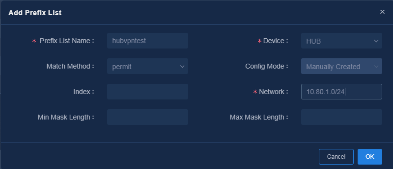
Figure 83 A prefix list is added
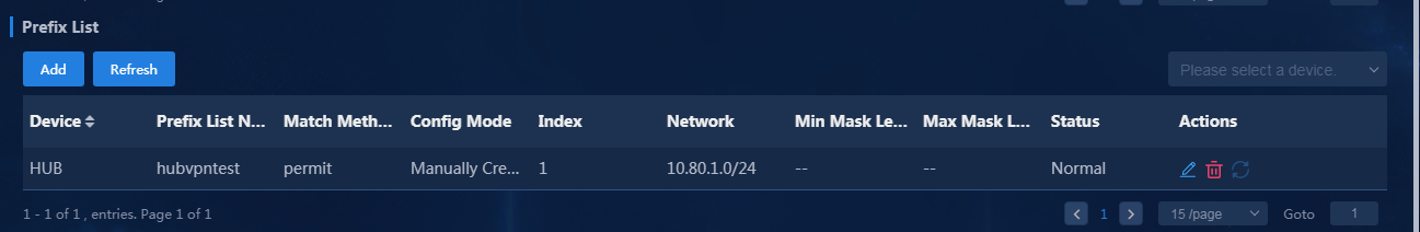
2. Add a routing policy. Add the corresponding matching rule on the Matching Rule page, as shown in Figure 84, and then click OK to save the configuration. On the Application Policy page, enter the community attribute, as shown in Figure 85, and then click OK to save the configuration. The format of the community attribute is "site ID:device ID". You can view the site ID and device ID on the Automation > Branch Network > Sites > Sites page on the controller, as shown in Figure 86.
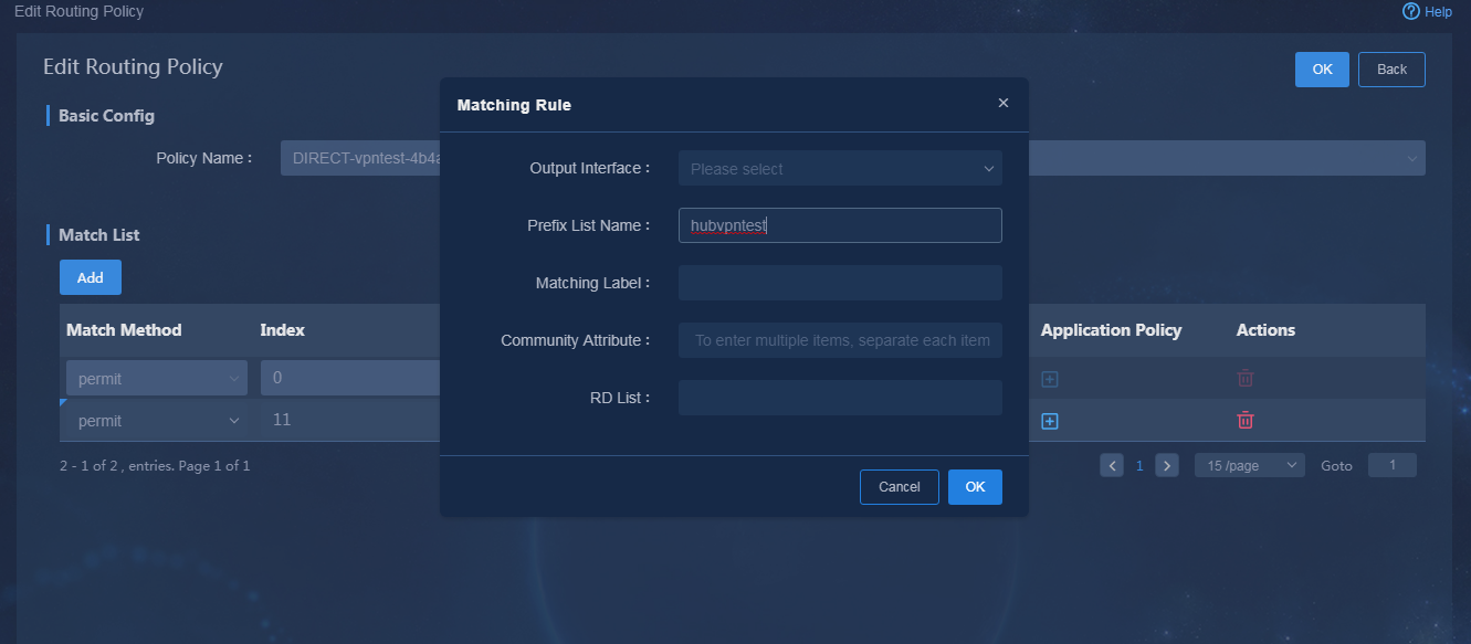
Figure 85 Application policy community attribute
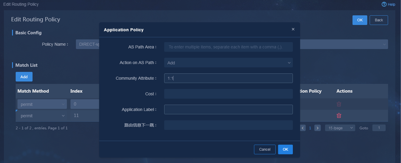
Figure 86 Querying site ID and device ID
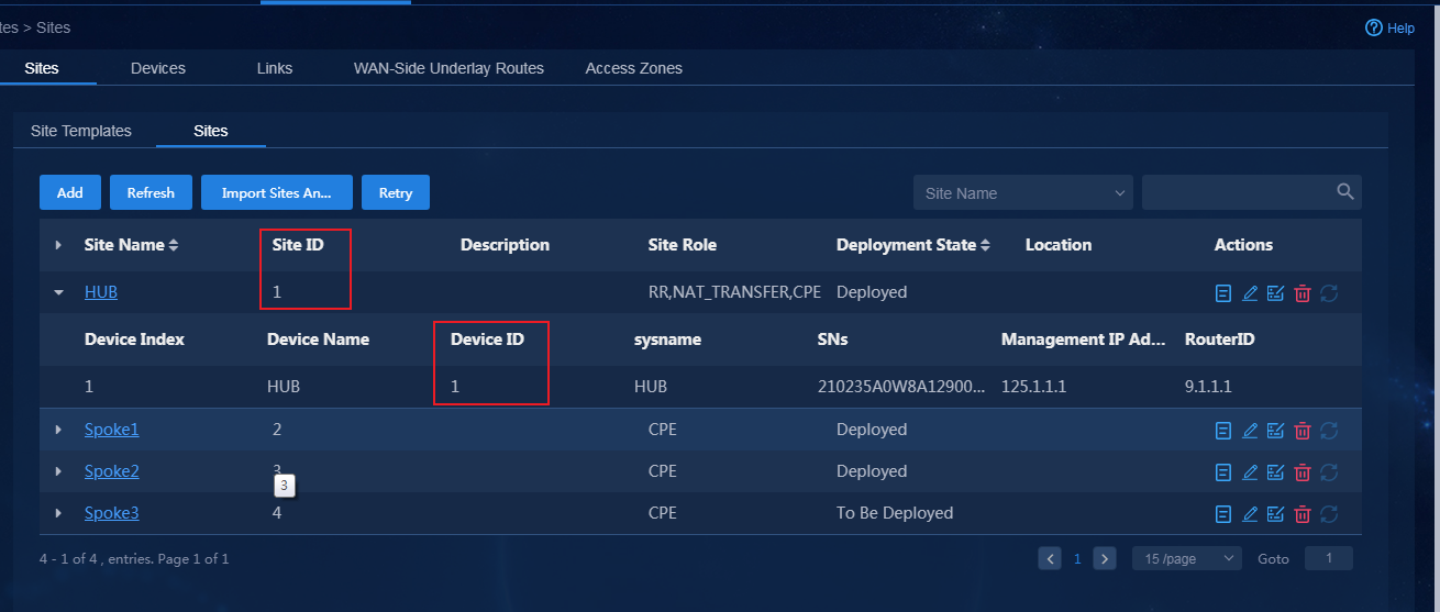
3. Navigate to the Automation > Branch
Network > Virtual Network > WAN-Side Overlay Routes
> BGP Routes page. Select the corresponding BGP-VPN instance and
click the Edit icon ![]() , as shown in Figure 87.
, as shown in Figure 87.
Figure 87 Editing BGP-VPN instances
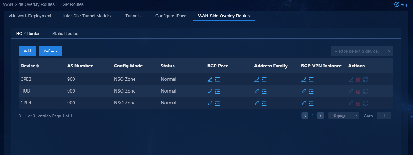
4. Click the ![]() icon in the Actions
column, and click the Details icon
icon in the Actions
column, and click the Details icon ![]() for the IPV4-UNICAST
address family. In the Route Redistribution Rule List area, configure
the routing protocol as Direct, and the routing policy as hubvpn1,
as shown in Figure 88. Click the Save icon
for the IPV4-UNICAST
address family. In the Route Redistribution Rule List area, configure
the routing protocol as Direct, and the routing policy as hubvpn1,
as shown in Figure 88. Click the Save icon ![]() in the Actions
column to save the configuration.
in the Actions
column to save the configuration.
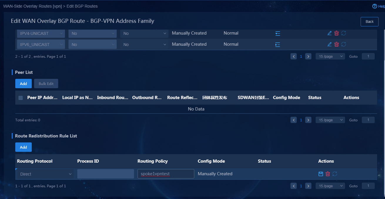
|
|
CAUTION: · For routing policies to take effect, make sure the prefix lists configured in the routing policies exactly match those in the routing table on the device. · For successful configuration deployment, you must configure an OSPF process number when OSPF routes are redistributed. |
Configure underlay TE by routing and route optimization
Redistribute BGP routes
This section uses the hub as an example to redistribute BGP service route 33.2.1.1/24 to OSPF and manually add a routing policy to filter service segments. The following information shows the manual configuration: (For other route advertisements, you can use the following configuration)
<hub>system-view
[hub]ip prefix-list net1 permit 33.2.1.0 24 //Create a prefix list to match only service segments.
[hub]route-policy net1 permit node 1
[hub-route-policy-net1-1]if-match ip address prefix-list net1 //Create a routing policy to match only service segments.
[hub-route-policy-net1-1]quit
[hub]ospf 20 vpn-instance vpn1 //Bind VPN1 to service segments and import it to OSPF of VPN.
[hub-ospf-1]import-route bgp 200 route-policy net1 //Add routing policy filtering to redistribute BGP routes to OSPF.
Query service status
Query the status of intra-VPN TE by routing
On device spoke1, display routing table information. Verify that traffic that matches the service segment routes is forwarded through overlay tunnels. All tunnels form ECMP links.
<spoke1>dis ip routing-table vpn-instance vpn1 33.1.1.1
Summary count : 1
Destination/Mask Proto Pre Cost NextHop Interface
33.1.1.0/24 BGP 255 0 110.1.1.1 Tun2
BGP 255 0 110.1.1.1 Tun1
BGP 255 0 110.1.1.1 Tun1
<spoke1>dis ip routing-table vpn-instance vpn2 35.1.1.1
Summary count : 1
Destination/Mask Proto Pre Cost NextHop Interface
35.1.1.0/24 BGP 255 0 110.1.1.1 Tun2
BGP 255 0 110.1.1.1 Tun1
BGP 255 0 110.1.1.1 Tun1
TE by routing is successful.
Application group traffic scheduling and visualization
To visualize traffic engineering and traffic path in topology view for user-defined applications, perform the following tasks:
1. Navigate to the Automation > Branch Network > Policies page to configure application groups (flow template).
2. Navigate to the Automation > Network Common Settings > QoS Management to configure traffic policies (qos policy).
Configure branch network application groups
Add policy scopes
Specify source devices according to the service scope. The controller deploys settings for an application group based on the policy scope bound to the application group.
1. Log in to Unified Platform as the tenant service administrator (sdwan1). Navigate to the Automation > Branch Network > Policies > Policy Scopes page.
2. Click Add to open the Add Policy Scopes page, and specify a policy scope name.
3. Click Add to add TE policies as shown in Figure 89. For information on TE policies, see Table 7.
Configuration description:
¡ Policy scope H-S is used for traffic scheduling between headquarters and branches, including the hub and spoke1.
¡ Policy scope S-S is used for traffic scheduling between branches, including the hub, spoke1. and spoke3.
¡ Policy scope H-S-ipv6 is used for IPv6 traffic scheduling between headquarters and branches, including the hub and spoke4.
Figure 89 Configuring policy scopes
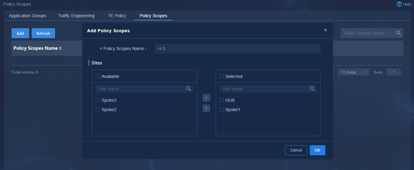
Add application policies
Configure an SLA policy
When the device performs session-based link selection, each session corresponds to traffic with an unambiguous quintuple. To select links for an application, define link quality requirements for the application. Application-based link selection is based on the link quality, the link bandwidth, and the link selection policies applied to the links.
· Basic link selection rules:
a. Selects the link with the highest priority from the links that meet the quality and bandwidth requirements.
b. Selects the link that meets the quality and bandwidth requirements and has the next highest priority if no link with the highest priority meets the quality or bandwidth requirements.
c. Randomly selects a link that meets the bandwidth requirements if no link meets the quality requirements.
d. Does not detect the link quality if no link meets the bandwidth requirements. Multiple links use UCMP. The links load share traffic based on their remaining bandwidths. A link does not meet the bandwidth requirements if its bandwidth usage exceeds 80%.
e. Does not use RIR to select links and performs routing table lookup to forward traffic if the bandwidth usage of all RIR candidate links reaches 100%.
· To configure SLA profiles:
The system has defined eight SLA levels that have priorities in the range of 0 to 7. The larger the priority value is, the higher the priority is. Each SLA level is defined with a set of quality parameters including latency, packet loss, and jitter, and the DSCP value for tunneled packets. You can manually change the quality parameter values for an SLA level.
a. Use tenant service administrator sdwan1 to log in to Unified Platform. Navigate to the Automation > Branch Network > Policies > TE Policy > SLA Profiles page, as shown in Figure 90.
Figure 90 SLA quality parameters
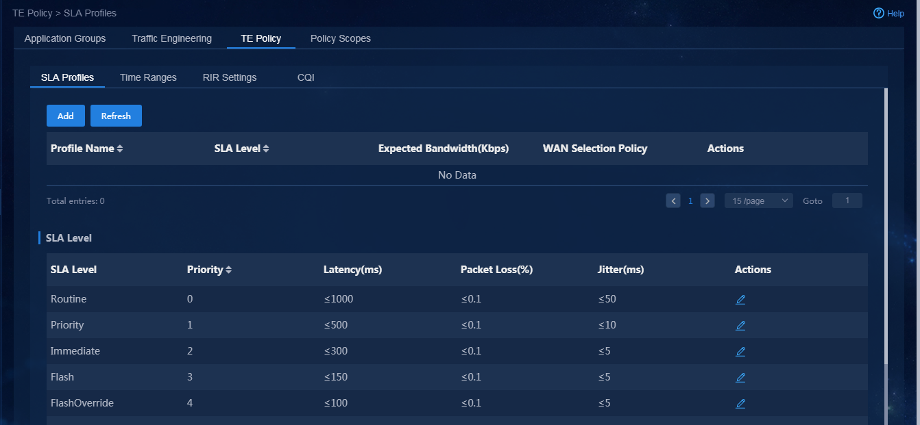
b. Click Add. An SLA profile contains the following content:
- SLA Level: Multiple application policies can use the same SLA level.
- Expected Bandwidth: Per-session expected bandwidth for initial link selection. As a best practice, set the expected bandwidth to 10 Kbps.
- WAN selection policy: Define optimal links for applications. You can add multiple optimal links and assign priority values to the links. The lower the priority value is, the higher the priority is.
In this example, four SLA profiles, SLA1, SLA3, SLA4, and SLA5, are added, as shown in Figure 91, Figure 92, Figure 93, and Figure 94, respectively.
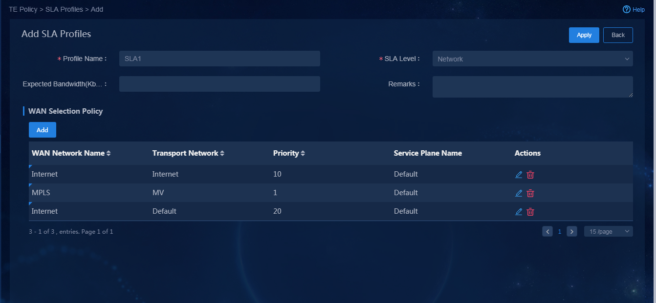

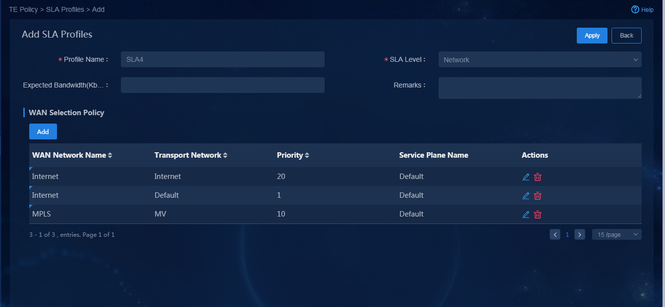
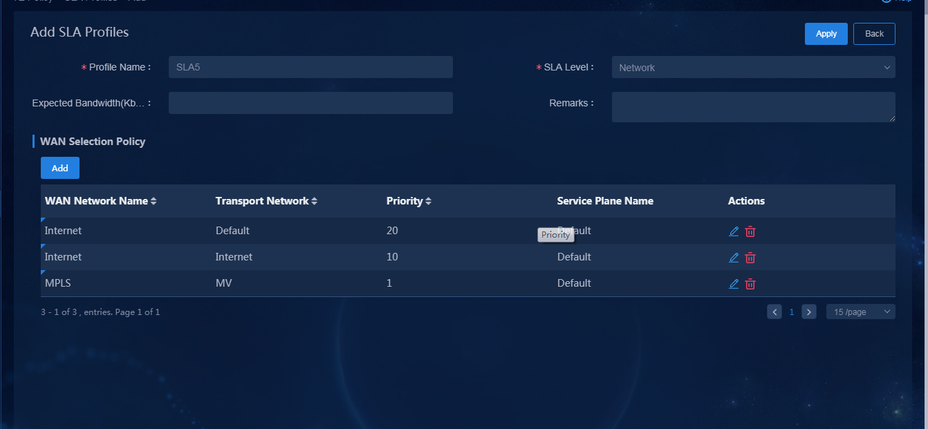
Configure time ranges
Use tenant service administrator sdwan1 to log in to Unified Platform. Navigate to the Automation > Branch Network > Policies > TE Policy > Time Ranges page. Click Add. In the dialog box that opens, add time range time1 as shown in Figure 95.
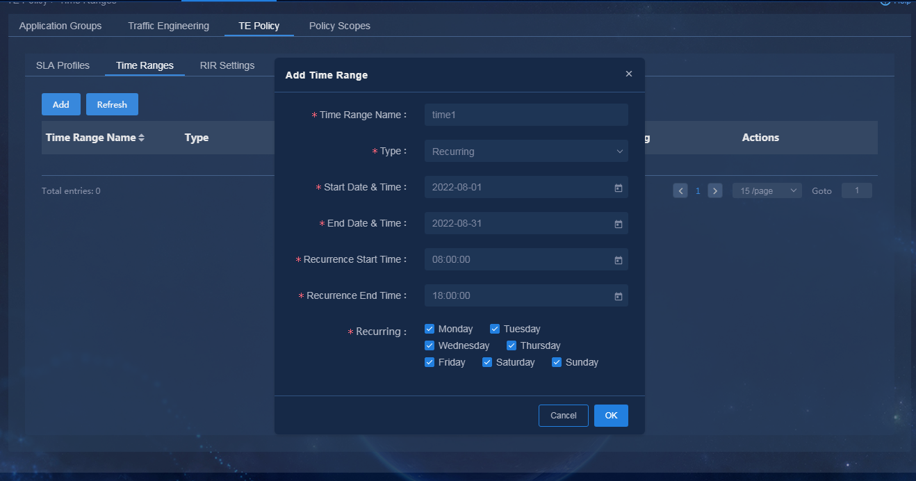
Add application groups
1. Use tenant service administrator sdwan1 to log in to Unified Platform. Navigate to the Automation > Branch Network > Policies > Application Groups page.
2. Click Add. Select a policy scope. In the Application Policy Group area, select the previously configured SLA policy, as shown in Figure 96. In this example, the application group name is app1.
Figure 96 Adding application groups
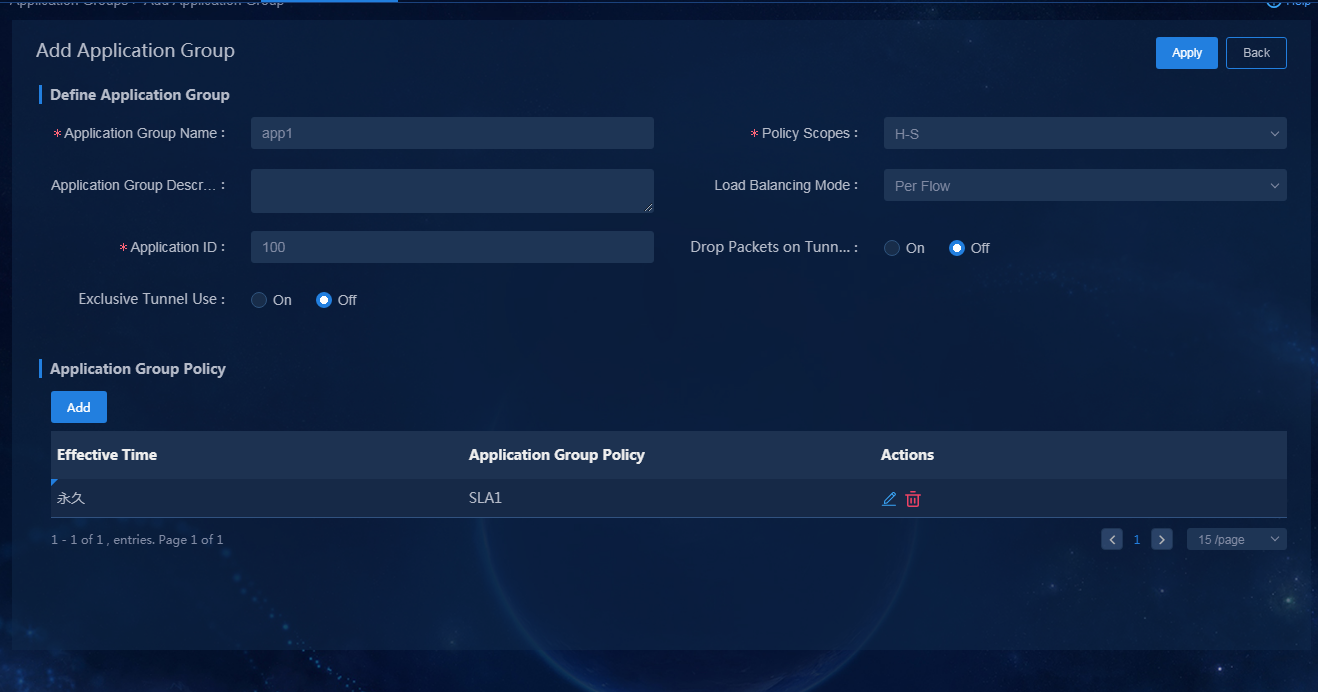
Key configuration description:
¡ Policy Scopes: The application group is deployed to all devices within the scope.
¡ Load Balancing Mode: The per-flow and per-packet load balancing modes are supported. As a best practice, use per-flow load balancing. If multiple links have the same priority, traffic can be distributed among the links for load balancing.
¡ Application ID: Flow ID of the application group, which is unique for each application group. It is used to configure the traffic behavior of QoS management.
¡ Application Group Policy: Options include permanent and time range-based. If time range-based is selected, you can select different time ranges for different application group policies.
Deploy application groups based on the TE requirements. The deployment succeeds when the deployment progress for each application group is 100%, as shown in Figure 97.
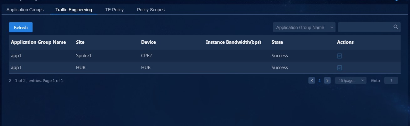
Configure QoS management traffic policy
For the defined traffic engineering and application path visualization to take effect, you must use the QoS management component to configure traffic policies after configuring the application group.
Configure ACL templates with quintuple application definition
To define an application:
1. Log in to Unified Platform as the tenant service administrator (sdwan1). Navigate to the Automation > Network Common Settings > QoS Management > ACL page, as shown in Figure 98. Click Add to add an ACL template with quintuple application definition, as shown in Figure 99.
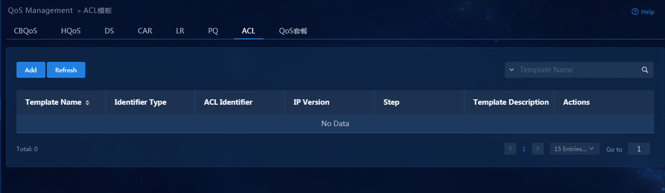
Figure 99 Adding an ACL template
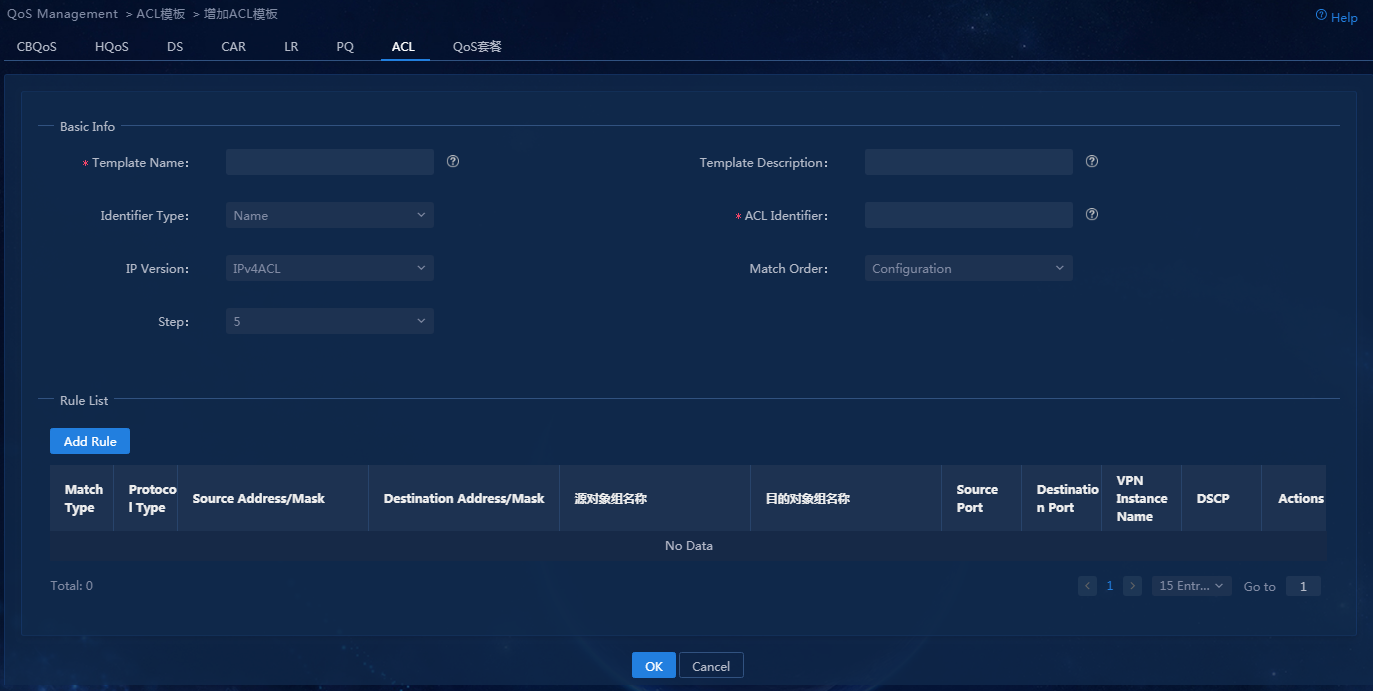
2. Click Add Rule to configure the ACL matching rules. Service traffic is bound to VPN instances, so you must specify the VPN instance name when adding the match rule. Click OK, as shown in Figure 100.
Figure 100 Adding a match rule
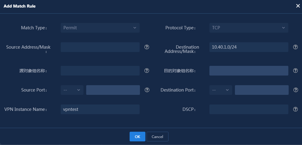
You can add multiple ACL rules and adjust the rule sequence, as shown in Figure 101.
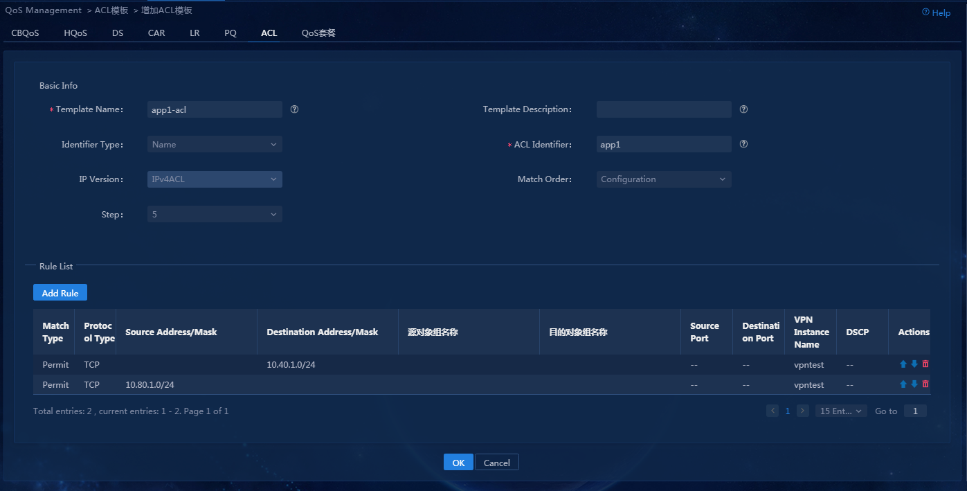
Parameters:
¡ Template Name: Specify the ACL template name displayed on the controller.
¡ Identifier Type: It is used to identify the command used to deploy the ACL configuration to the device. For a name identifier, a command like acl advance name app1 is used. For a digit identifier, a command like acl advance 3000 is used.
¡ ACL Identifier: ACL name identifier or digit identifier deployed to the device.
¡ IP Version: Select IPv4ACL or IPv6ACL.
3. Click OK to save the ACL template, as shown in Figure 102.
Figure 102 Configuring ACL templates
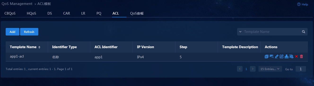
4. Follow the above steps to configure the ACL templates for other service traffic. After the configuration is completed, the page is as shown in Figure 103 is displayed.
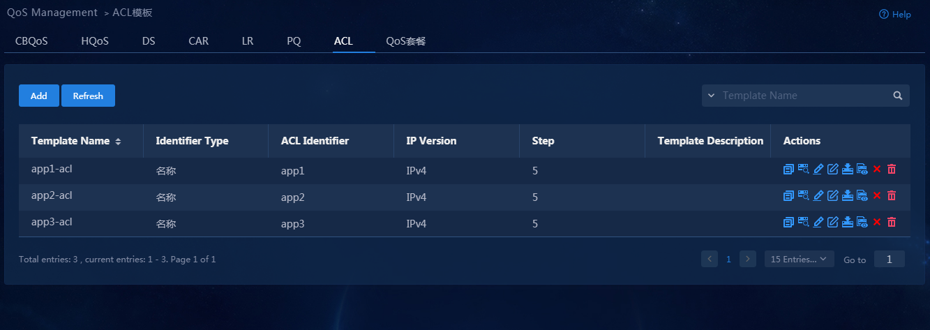
Configure traffic classifier templates
1. Log in to Unified Platform as the tenant service administrator (sdwan1). Navigate to the Automation > Network Common Settings > QoS Management > CBQoS > Traffic Classifier page, as shown in Figure 104.
Figure 104 Traffic Classifier page
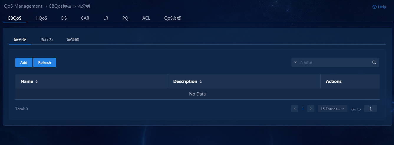
2. Click Add to open the page for adding traffic classifiers, as shown in Figure 105.
3. Parameters:
¡ Name: Name of the traffic classifier.
¡ Rule Logic: Logical relation between multiple matching rules, including and and or.
Figure 105 Adding a traffic classifier
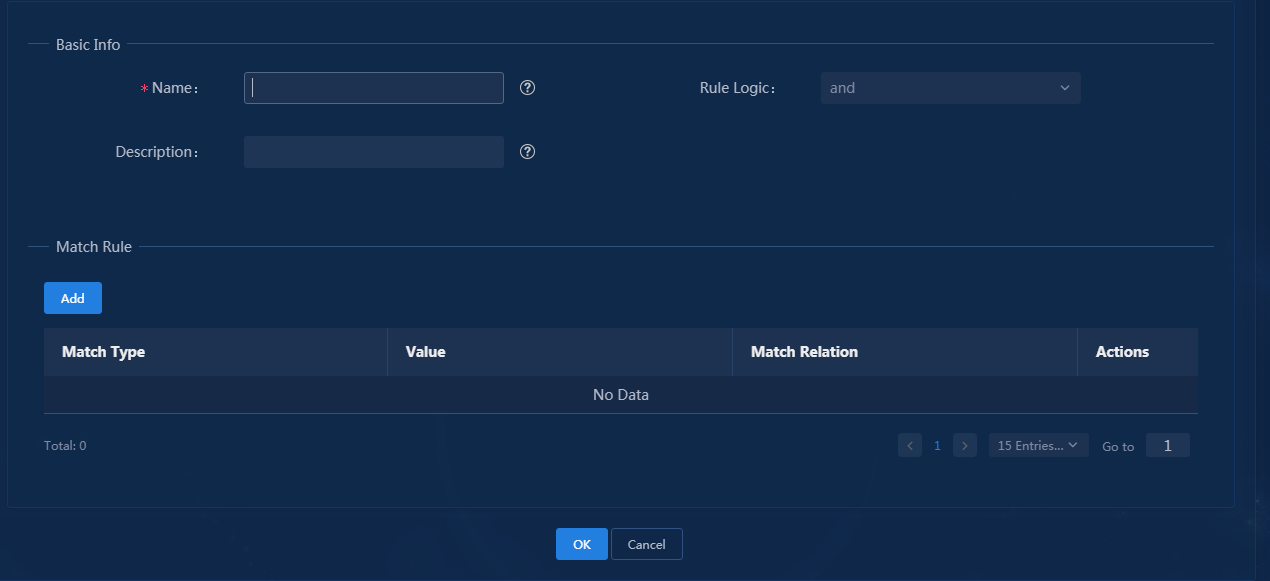
4. Click Add in the Match Rule area to configure traffic characteristics. The match type supports multiple options. In this example, select ACL for Match Type, as shown in Figure 106.
Figure 106 Traffic characteristics
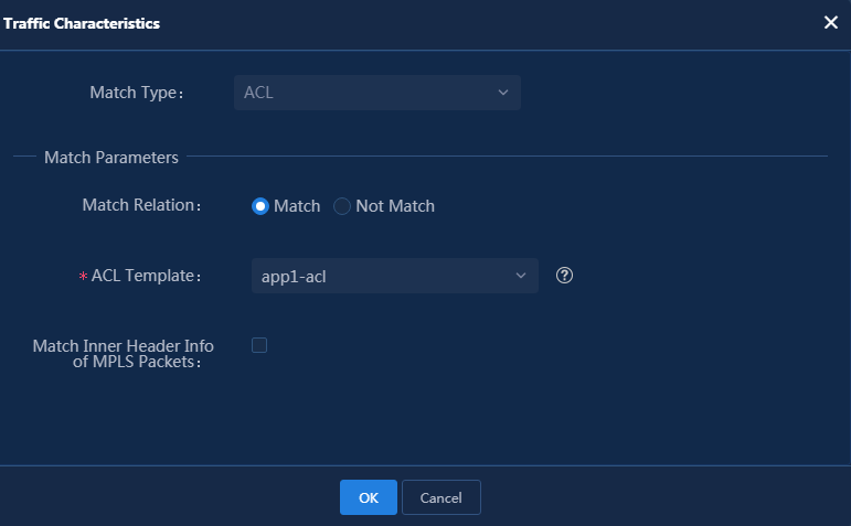
5. Click OK, as shown in Figure 107. You can also specify multiple matching rules for traffic classifiers.
Figure 107 Traffic classifier matching rule list
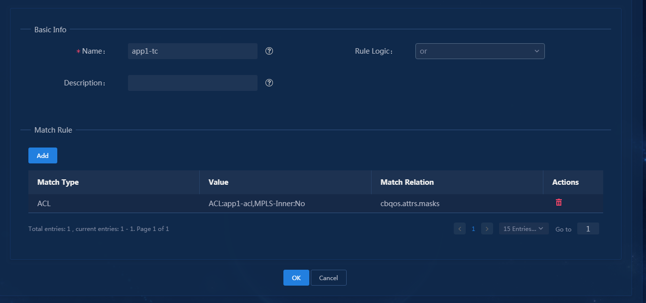
6. Click OK to save the traffic classifier template, as shown in Figure 108.
Figure 108 Traffic classifier template
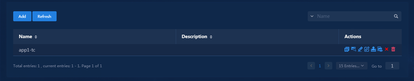
7. Follow the above steps to configure other traffic templates. After the configuration is completed, the page is as shown in Figure 109 is displayed.
Figure 109 All traffic classifier templates
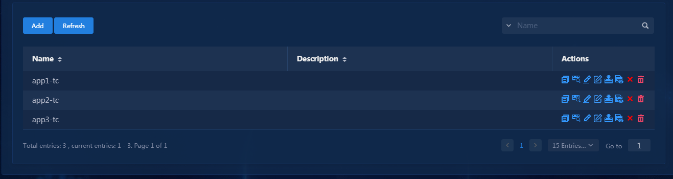
Configure traffic behavior templates
1. Log in to Unified Platform as the tenant service administrator (sdwan1). Navigate to the Automation > Network Common Settings > QoS Management > CBQoS > Traffic Behavior page, as shown in Figure 110. Click Add to add traffic behaviors, as shown in Figure 111 and Figure 112.
Figure 110 Traffic behavior page
Figure 111 Adding traffic behaviors-1
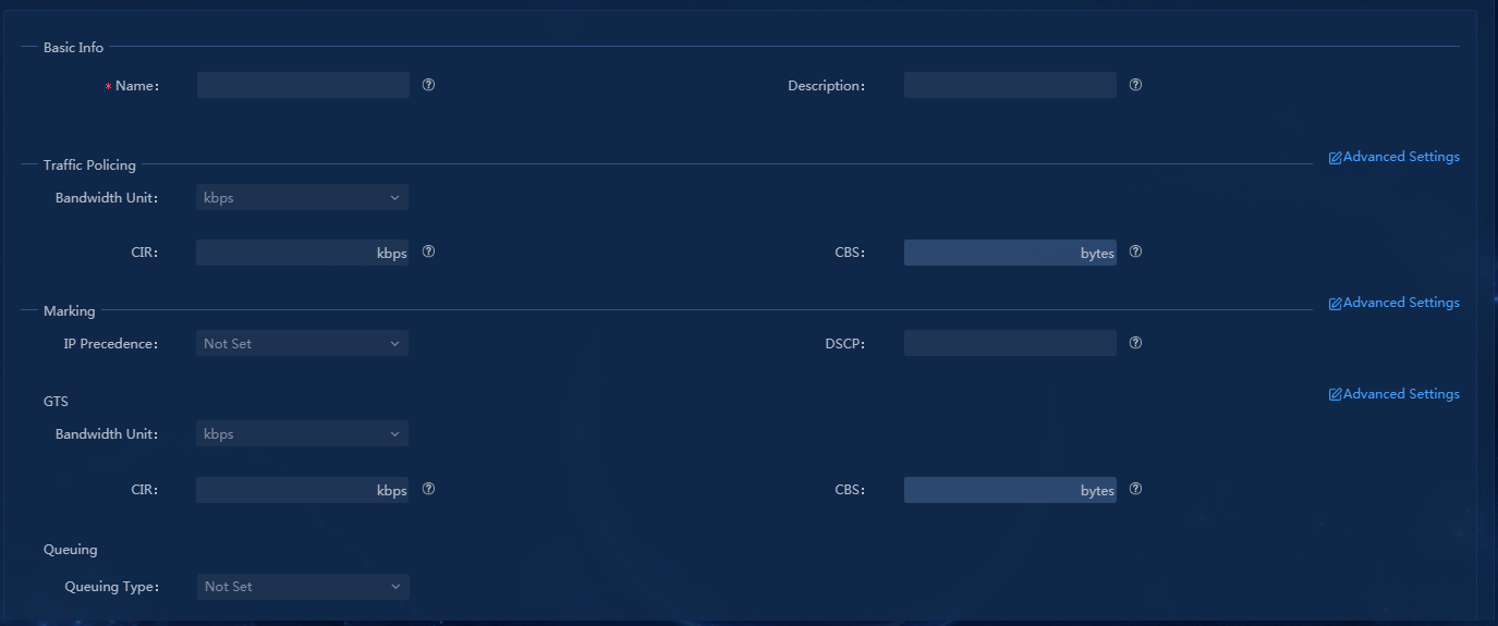
Figure 112 Adding traffic behaviors-2
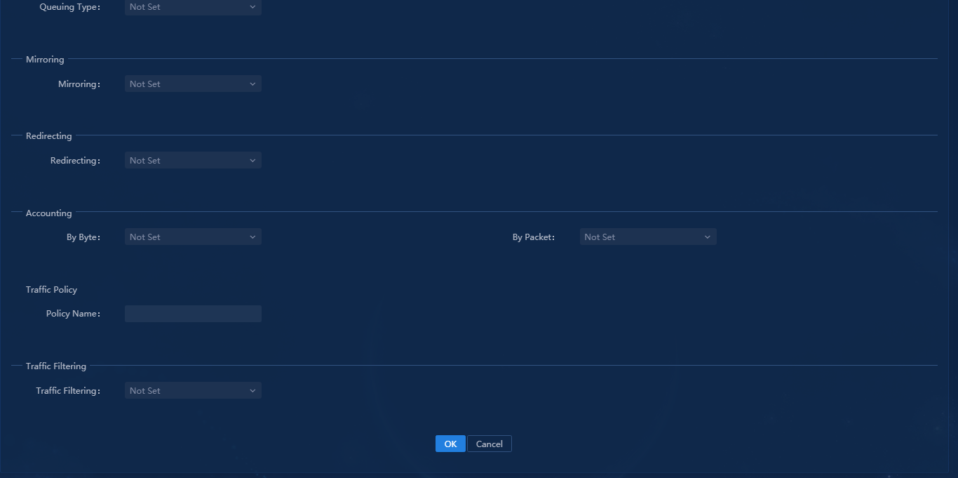
2. Click the Advanced Settings link for Marking, enter the Flow ID, DSCP, and Tunnel DSCP, as shown in Figure 113, and then click OK.
Figure 113 Configuring marking
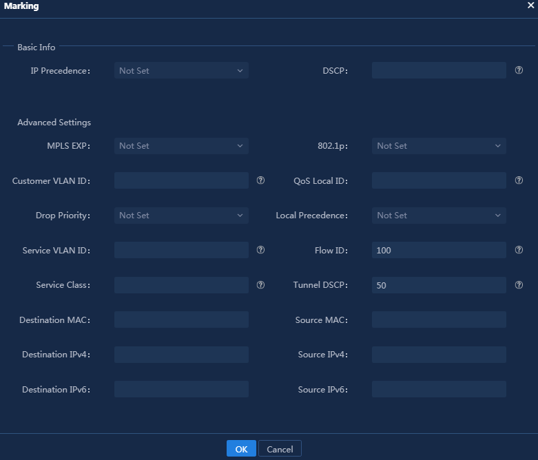
Parameters:
¡ Flow ID: Enter the application ID configured in “Add application groups.”
¡ DSCP: DSCP value for packets. This value is used to configure QoS application assurance on tunnel interfaces. In this example, the DSCP for app1 and app2 is 50 and 40, respectively, and the traffic behavior of other traffic is not configured.
¡ Tunnel DSCP: DSCP value for tunnel encapsulated packets. This value is used to configure QoS application assurance on interfaces. If you do not configure application assurance, you can leave this field blank. In this example, the tunnel DSCP for app1 and app2 is 50 and 40, respectively, and the traffic behavior of other traffic is not configured.
3. Click OK to save the configuration, as shown in Figure 114.
Figure 114 Traffic behavior template
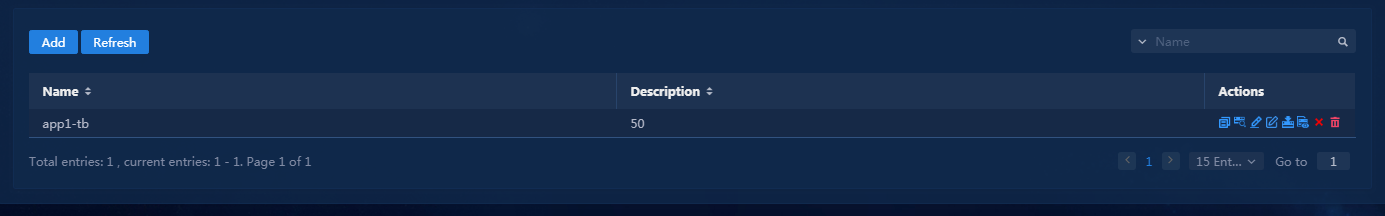
4. Follow the above steps to configure other traffic behaviors, as shown in Figure 115.
Figure 115 All traffic behavior templates
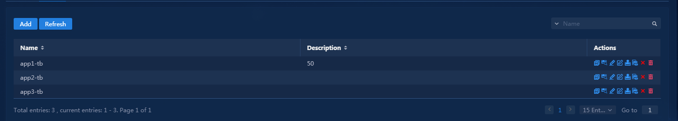
Configure traffic policy templates
1. Log in to Unified Platform as the tenant service administrator (sdwan1). Navigate to the Automation > Network Common Settings > QoS Management > CBQoS > Traffic Policy page, as shown in Figure 116.
Figure 116 Traffic policy page
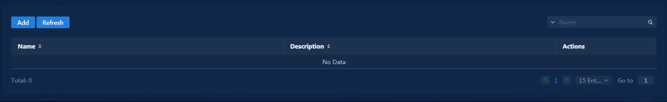
2. Click Add to open the page for adding traffic policies, as shown in Figure 117.
Figure 117 Adding a traffic policy
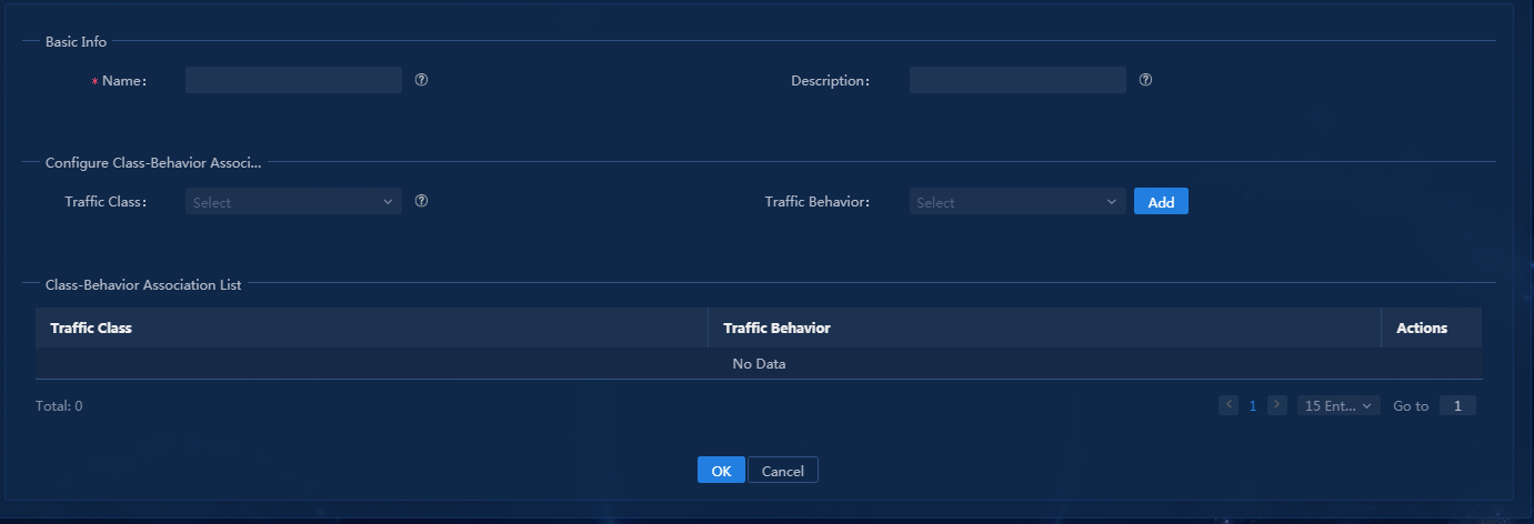
3. Select a traffic classifier and a traffic behavior, as shown in Figure 118, and then click Add to associate the traffic classifier and its corresponding traffic behavior to the class-behavior association list, as shown in Figure 119.
Figure 118 Binding the traffic classifier and the traffic behavior
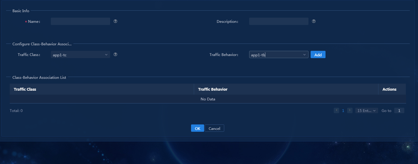
Figure 119 Binding class-behavior association successfully
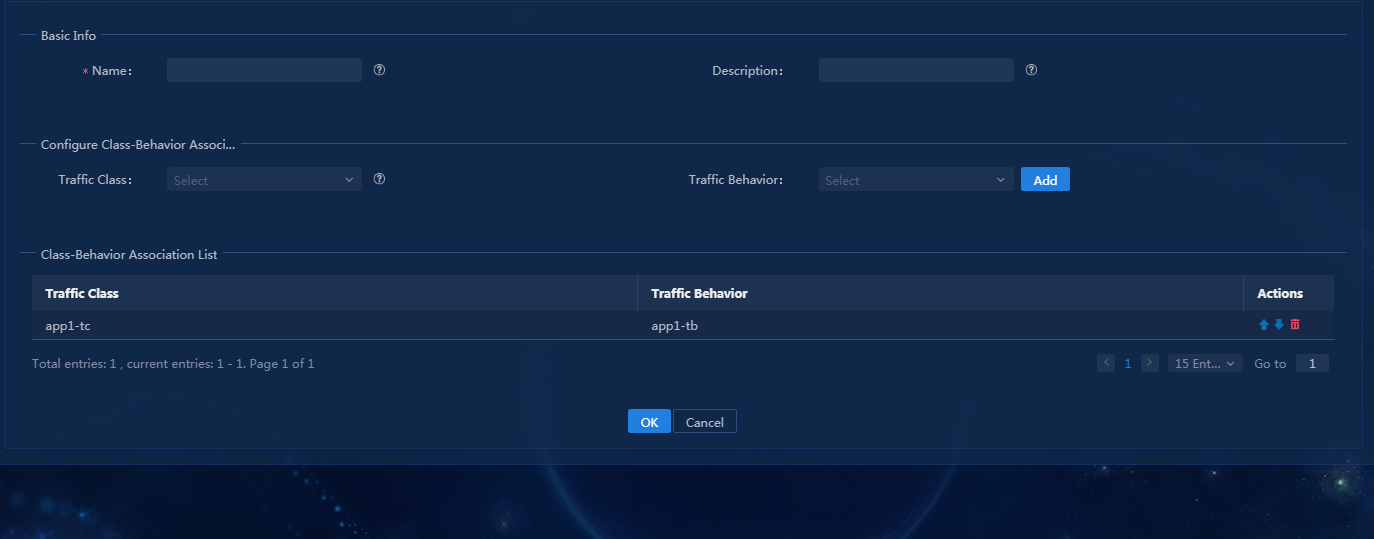
You can add
multiple class-behavior associations for a traffic policy. Typically, a traffic policy (QoS policy) will be
bound to multiple groups of traffic classifiers and traffic behaviors. You can
click the ![]() icon to adjust the matching sequence, as shown in Figure 120.
icon to adjust the matching sequence, as shown in Figure 120.
Figure 120 Class-Behavior Association List
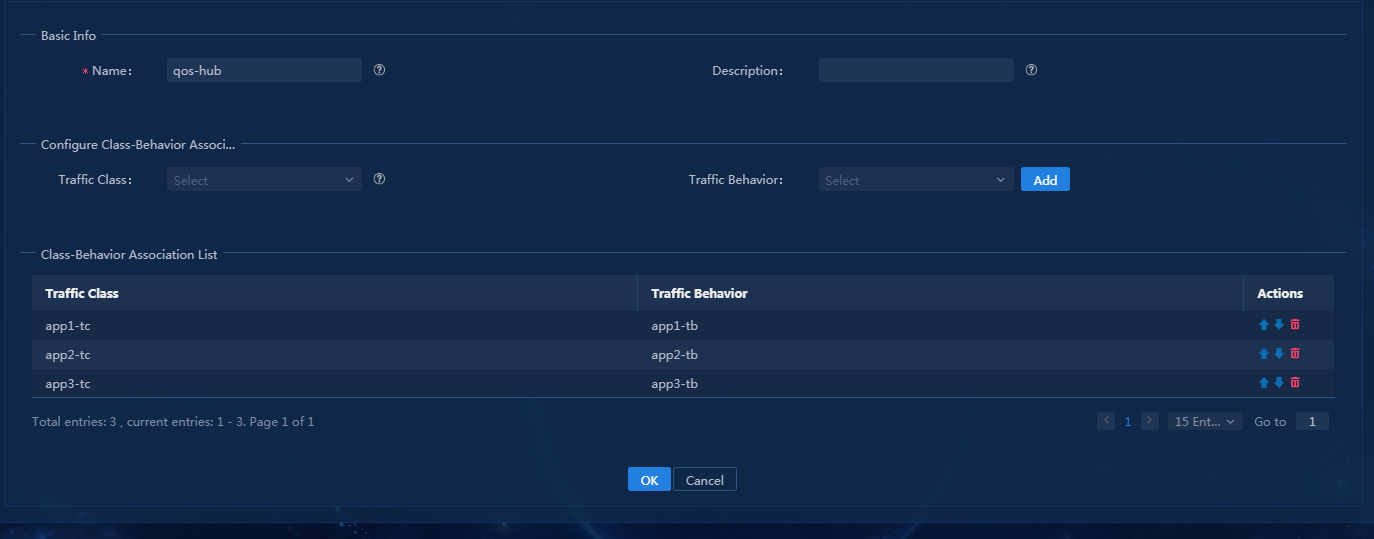
4. Click OK to save configuration of the traffic policy template, as shown in Figure 121.
Figure 121 Traffic policy template
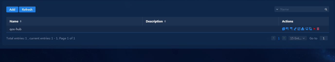
5. Click the ![]() icon in the Actions
column to access the page for
deploying the application group configuration to device interfaces, as shown in
Figure 122.
icon in the Actions
column to access the page for
deploying the application group configuration to device interfaces, as shown in
Figure 122.
Figure 122 Deploy to Interface page

6. Click Select Interfaces, as shown in Figure 123. Typically, configure the application group to LAN interfaces of the device.
Figure 123 Select Interfaces page
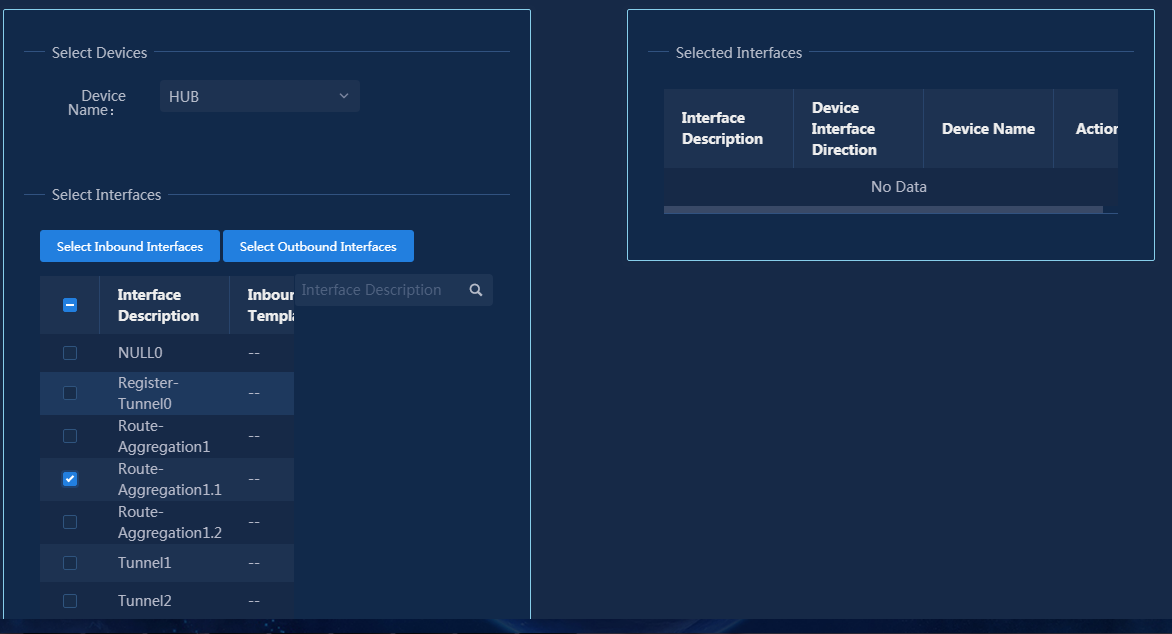
7. Select hub. Select interfaces and click Select Inbound Interfaces to add the interfaces to the selected interface list, as shown in Figure 124. You can add multiple inbound interfaces to the selected interface list.
Figure 124 Selected interfaces
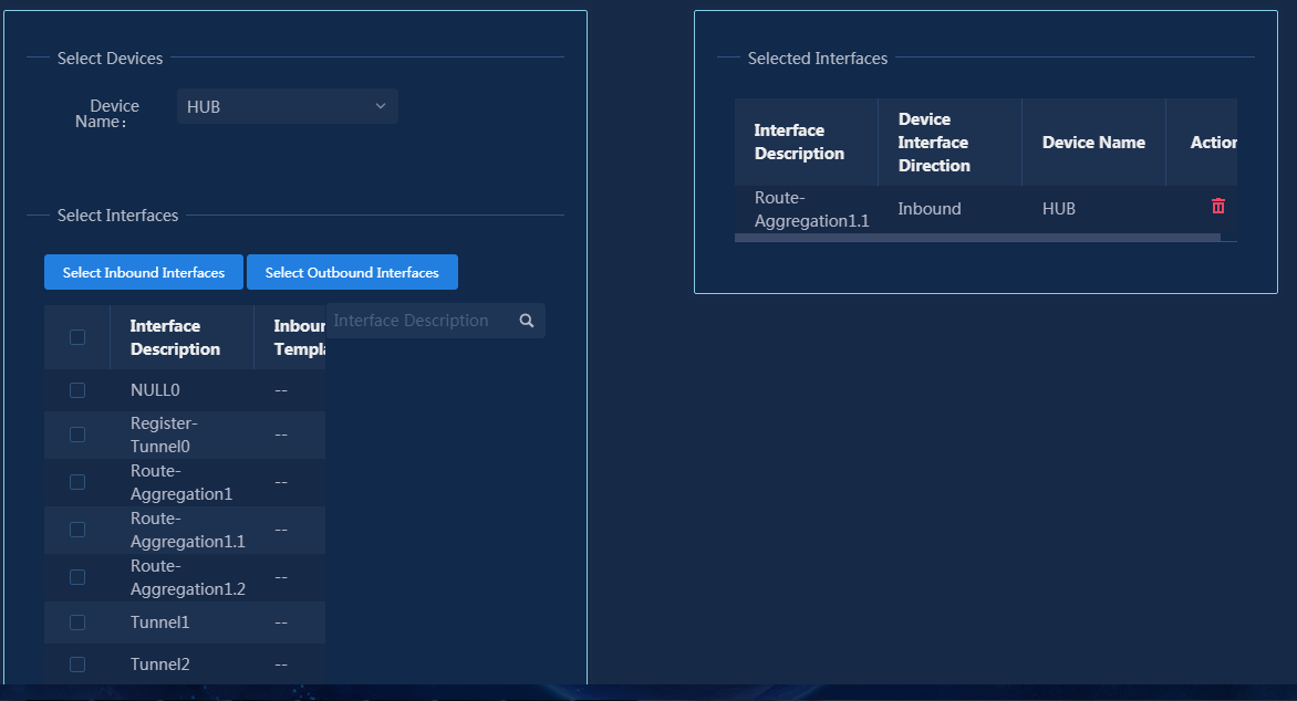
8. Click OK to save the interfaces to be applied to the traffic policy, as shown in Figure 125.
Figure 125 Selected interface to be deployed
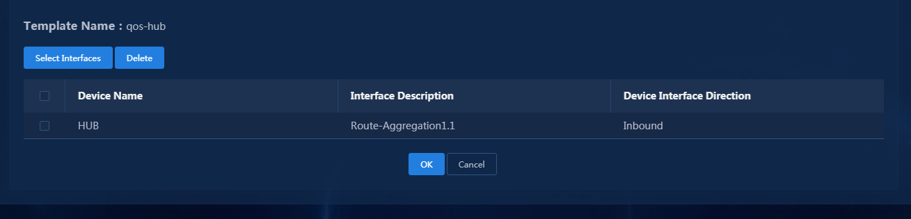
9. Click OK, as shown in Figure 126.
Figure 126 Deployment was successful
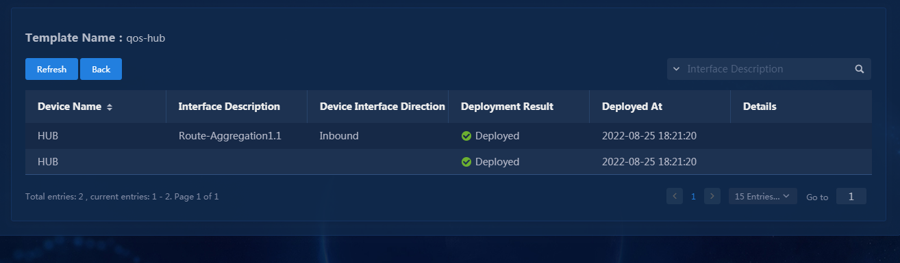
10. Follow the above steps to configure other traffic policies. Traffic policies configured on the same device interface can be configured in the same template. After the configuration is completed, the page as shown in Figure 127 is displayed.
Figure 127 Templates for all processes
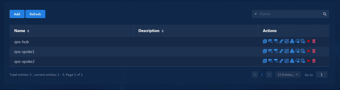
Verify the configuration
1. Simulate traffic that matches the
application group app1. Navigate to the Monitor > Topology
> Branch Topology page. Click the Application Groups icon ![]() to
display all application groups. Then, select application group app1 to
view forwarding paths for traffic that matches the application group, as shown
in Figure 128. Application traffic is forwarded through MV’s Layer 3 leased lines
as expected.
to
display all application groups. Then, select application group app1 to
view forwarding paths for traffic that matches the application group, as shown
in Figure 128. Application traffic is forwarded through MV’s Layer 3 leased lines
as expected.
Figure 128 Forwarding paths for application group app1
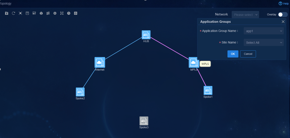
2. Simulate traffic that matches the
application group app3. Navigate to the Monitor > Topology
> Branch Topology page. Click the Application Groups icon ![]() to
display all application groups. Then, select application group app3 to
view forwarding paths for traffic that matches the application group, as shown
in Figure 129. Application traffic is forwarded through the Internet as expected.
Besides, VPN1 is in the HUB-SPOKE model, so the traffic between branches is
forwarded through HQ Site1.
to
display all application groups. Then, select application group app3 to
view forwarding paths for traffic that matches the application group, as shown
in Figure 129. Application traffic is forwarded through the Internet as expected.
Besides, VPN1 is in the HUB-SPOKE model, so the traffic between branches is
forwarded through HQ Site1.
Figure 129 Forwarding paths for application group app3
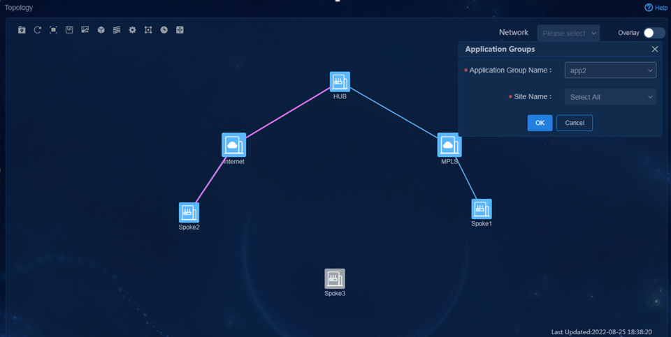
3. Simulate traffic (IPv6) that matches the
application group app4. Navigate to the Monitor > Topology
> Branch Topology page. Click the Application Groups icon ![]() to
display all application groups. Then, select application group app4 to
view forwarding paths for traffic that matches the application group, as shown
in Figure 130. Application traffic is forwarded through the Internet as expected.
to
display all application groups. Then, select application group app4 to
view forwarding paths for traffic that matches the application group, as shown
in Figure 130. Application traffic is forwarded through the Internet as expected.
Figure 130 Forwarding paths for application group app4
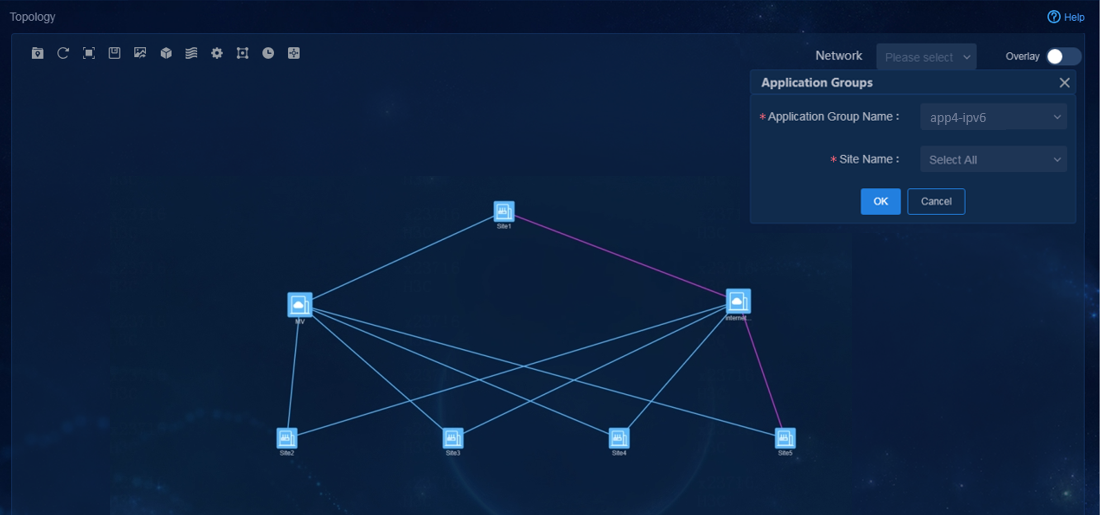
4. Simulate traffic that matches the
application group app5. Navigate to the Monitor > Topology
> Branch Topology page. Click the Application Groups icon ![]() to
display all application groups. Then, select application group app5 to
view forwarding paths for traffic that matches the application group, as shown
in Figure 131. Application traffic is forwarded through MV’s Layer 3 leased lines
as expected. Besides, VPN2 is in the FULL-MESH model, so the traffic between
branches is forwarded directly.
to
display all application groups. Then, select application group app5 to
view forwarding paths for traffic that matches the application group, as shown
in Figure 131. Application traffic is forwarded through MV’s Layer 3 leased lines
as expected. Besides, VPN2 is in the FULL-MESH model, so the traffic between
branches is forwarded directly.
Figure 131 Forwarding paths for application group app5
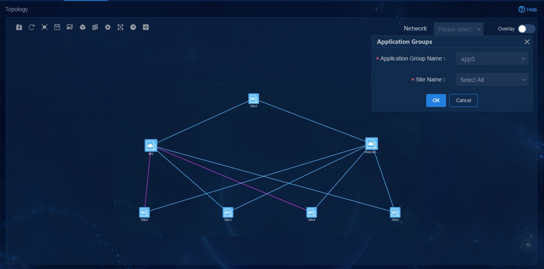
|
|
CAUTION: To ensure that the topology displays forwarding paths, make sure the network has traffic that matches the application groups. |
Exclusive tunnel use feature
For an application to exclusively use a tunnel, you can enable exclusive tunnel use.
When exclusive tunnel use is enabled, the following rules apply:
· When the corresponding tunnel does not transmit application traffic that exclusively occupies the tunnel, the tunnel can transmit other application traffic.
· When the corresponding tunnel transmits application traffic that exclusively occupies the tunnel, the system automatically switches other application traffic from the tunnel to other tunnels.
Procedure
1. After TE application groups are added, edit the application group app2 and enable exclusive tunnel use, as shown in Figure 132.
Figure 132 Enabling exclusive tunnel use

2. View the application group information. Application groups app1 and app2 use the same SLA profile and exclusive tunnel use is enabled for app2, as shown in Figure 133.
Figure 133 Application group list

|
|
CAUTION: If you enable exclusive tunnel use for an application group, links in the application group are used exclusively by traffic that matches the application group when such traffic exists. A link can belong only to one application group enabled with the exclusive tunnel use feature. |
Verify the configuration
1. Simulate traffic that matches the
application group app1. Navigate to the Monitor > Topology
> Branch Topology page. Click the Application Groups icon ![]() in
the top toolbar to display all application groups. Then, select application
group app1 to view forwarding paths for traffic that matches the
application group, as shown in Figure 134.
Application traffic is forwarded through Layer 2 leased lines as expected.
in
the top toolbar to display all application groups. Then, select application
group app1 to view forwarding paths for traffic that matches the
application group, as shown in Figure 134.
Application traffic is forwarded through Layer 2 leased lines as expected.
Figure 134 Forwarding paths for application group app1
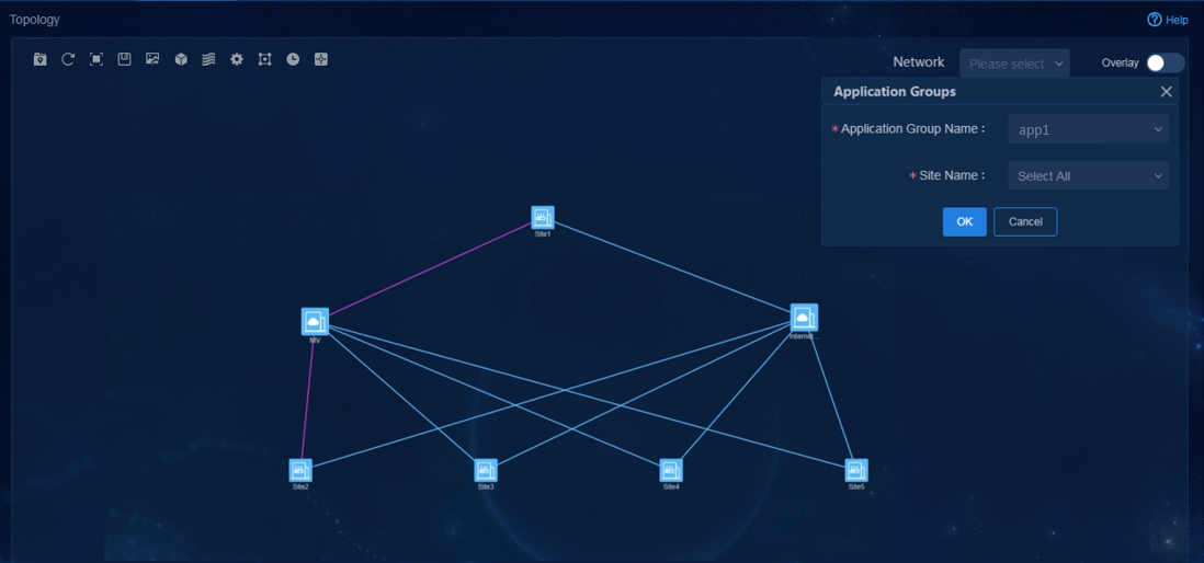
2. Simulate traffic that matches the
application group app2 in addition to app1. Navigate to the Monitor
> Topology > Branch Topology page. Click the Application
Groups icon ![]() in the top toolbar to display all application groups. Then, select
application group app2 to view forwarding paths for traffic that matches
the application group, as shown in Figure 135.
Application traffic is forwarded through Layer 3 leased lines.
in the top toolbar to display all application groups. Then, select
application group app2 to view forwarding paths for traffic that matches
the application group, as shown in Figure 135.
Application traffic is forwarded through Layer 3 leased lines.
Figure 135 Forwarding paths for application group app2
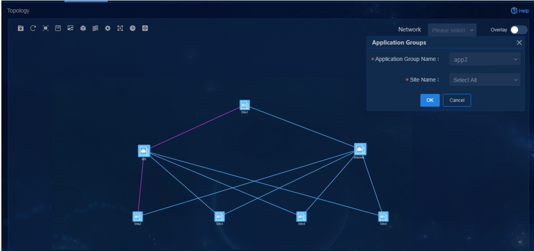
3. View forwarding paths for traffic that matches application group app1. Verify that the exclusive tunnel use feature can take effect. Traffic from spoke1 to the hub is switched to MV leased lines, as shown in Figure 136.
Figure 136 Forwarding paths for application group app1

Deploy QoS services
The controller supports the following QoS service deployments:
· Rate limit for WAN interfaces: The link bandwidth parameters are specified when links are added. The rate limit is based on the bandwidth.
· Application assurance for WAN interfaces: When a WAN interface is congested, the interface allocates different bandwidths to different applications according to the application priorities.
· Application blocking for LAN interface: Identify the traffic and deny forwarding.
Configure rate limit for WAN interfaces
Deployment flow for physical interfaces
When you configure WAN network details, specify bandwidth parameters for interfaces. The controller supports limiting the rate of WAN interfaces based on the configuration.
1. Log in to Unified Platform as the tenant service administrator (sdwan1). Navigate to the Automation > Network Public Settings > QoS Management > LR page, as shown in Figure 137.
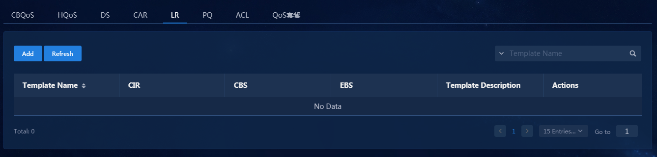
2. Click Add to configure the LR template, as shown in Figure 138. For example, you can limit the rate of the WAN interface of spoke1 to 3000 Kbps.
Figure 138 Adding an LR template
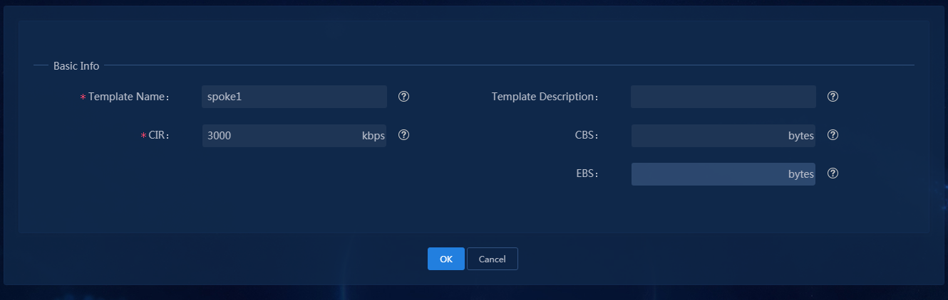
3. Click OK to save the template, as shown in Figure 139.
Figure 139 LR template created successfully

4. Click the ![]() icon in the Actions
column to apply the LR template to the device interface. Click Select
Interfaces as shown in Figure 140.
icon in the Actions
column to apply the LR template to the device interface. Click Select
Interfaces as shown in Figure 140.
Figure 140 Selecting interfaces
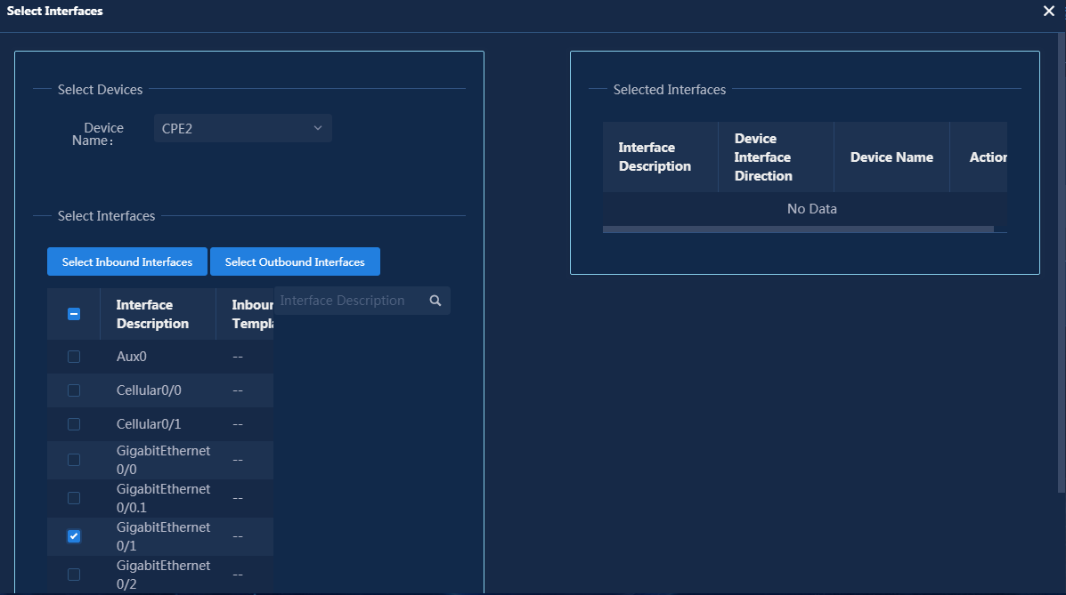
5. Select the device name, select an interface, and click Select Outbound Interfaces to add the interface to the selected interface list, as shown in Figure 141.
Figure 141 Selected interfaces
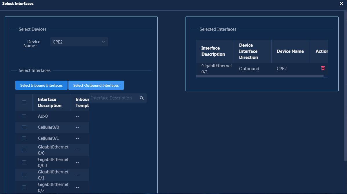
6. Click OK to save the selected interface list, as shown in Figure 142.
Figure 142 Selected interface
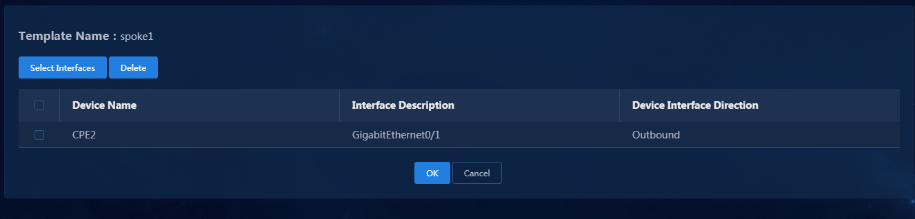
7. Click OK to deploy the template to the device interface, as shown in Figure 143.
Figure 143 Deployment was successful
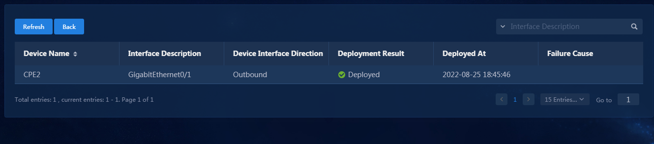
Verify the configuration
1. Simulate traffic that exceeds the upper limit and verify that the rate limit settings can take effect.
2. Rate limit for physical interfaces: Check WAN interface configuration on the device and verify that the rate limit settings have been deployed to a physical interface.
<spoke1>dis cu int GigabitEthernet 0/1
#
interface GigabitEthernet0/1
port link-mode route
bandwidth 10000
combo enable copper
ip address 80.2.1.2 255.255.255.0
ospf 10 area 0.0.0.10
qos lr outbound cir 3000 cbs 187500 ebs 0
#
Configure QoS application assurance
When a WAN interface is congested, the interface allocates bandwidths to applications based on the application priorities.
In the EVPN solution, the egress of the HQ device corresponds to multiple branches and the egress bandwidth of HQ devices is generally greater than that of branch devices. Therefore, when configuring application assurance, configure bandwidth assurance on an interface for branch devices, configure bandwidth assurance for HQ devices on tunnel interfaces for different branches.
This section takes an example of the configuration of application groups app1 and app2, with the SLA application policy of the scheduling path being the same and the exclusive tunnel use feature being disabled. The Remark DSCP and Tunnel DSCP of the traffic behavior for app1 are set to 50, while those for app2 are set to 40.
Configure application assurance templates via QoS management
1. Create a traffic identifier. Click Match Rule to configure DSCP and Tunnel DSCP. In this example, DSCP and Tunnel DSCP for app1 are set to 50, and those for app2 are set to 40, as shown in Figure 144 and Figure 145.
Figure 144 Creating traffic classifiers-1
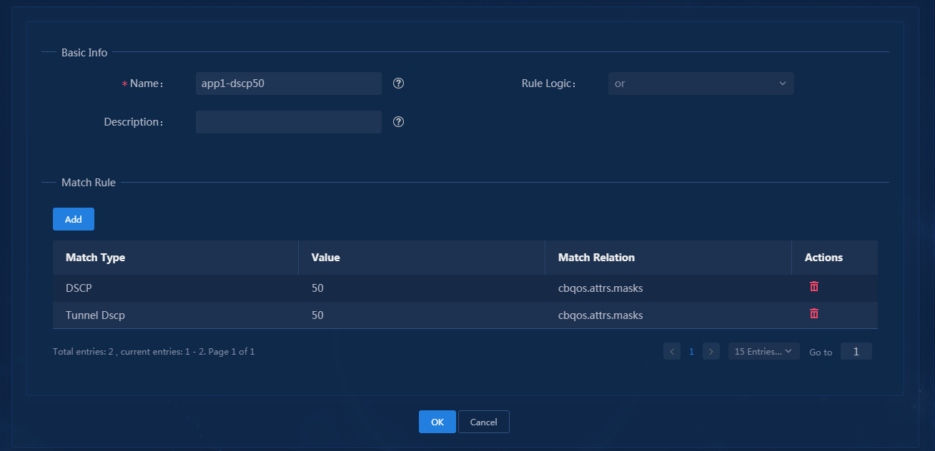
Figure 145 Creating traffic classifiers-2
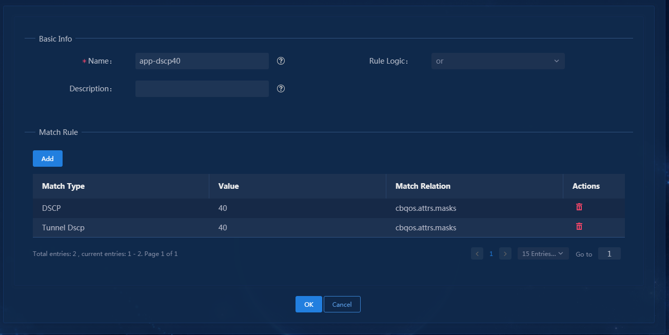
2. Create a traffic behavior. Click Add to configure queues. For example, configure the bandwidth of app1 af queue with a bandwidth value of 1600 Kbps and app2 ef queue with a bandwidth value of 1400 Kbps, as shown in Figure 146 and Figure 147.
Figure 146 Creating traffic behaviors-1

Figure 147 Creating traffic behaviors-2
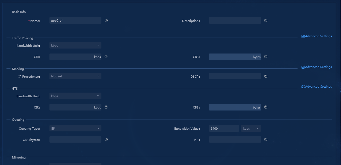
3. Create a traffic policy. Select a group of traffic classifier and traffic behavior, and then click Add to bind the traffic classifier and traffic behavior to the class-behavior association list, as shown in Figure 148.
Figure 148 Creating a traffic policy
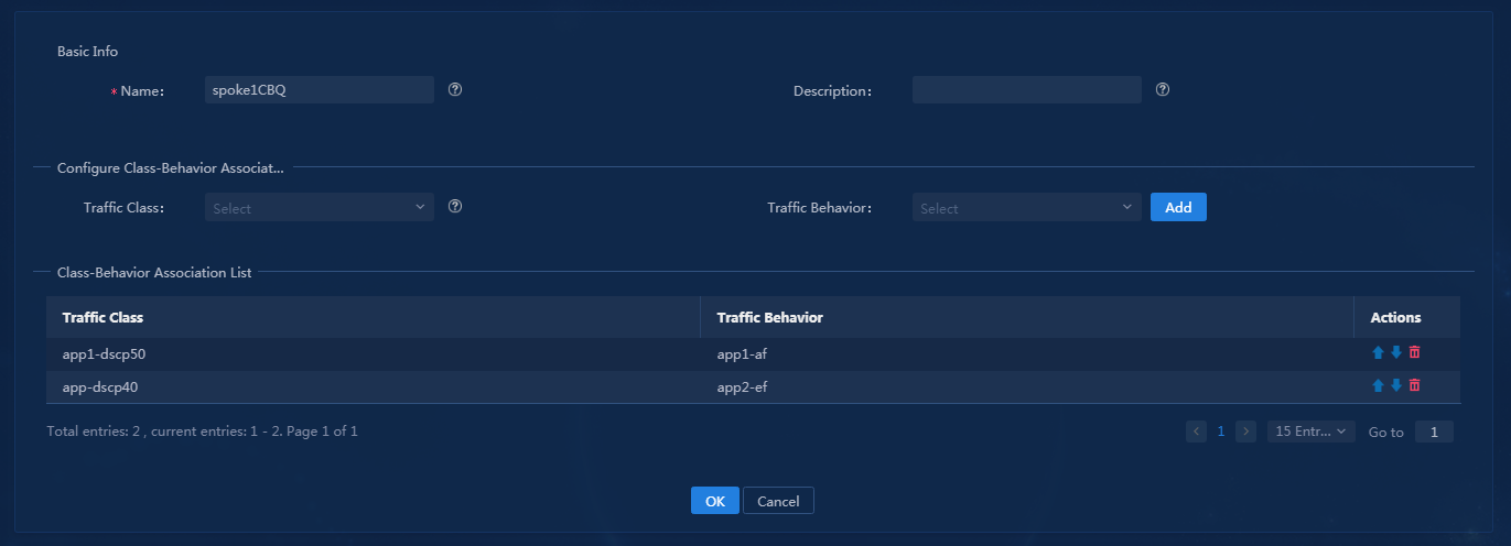
Configure application assurance templates on branch devices (physical interfaces applications)
Configure rate limit for physical interfaces. This section takes as an example of limiting the rate to 3000 Kbps.
1. Click the ![]() icon in the Actions
column for a traffic policy and click Select Interfaces. For example,
select outbound interface GigabitEthernet0/1 of spoke1, as shown
in Figure 149.
icon in the Actions
column for a traffic policy and click Select Interfaces. For example,
select outbound interface GigabitEthernet0/1 of spoke1, as shown
in Figure 149.
Figure 149 Selecting deployment interfaces
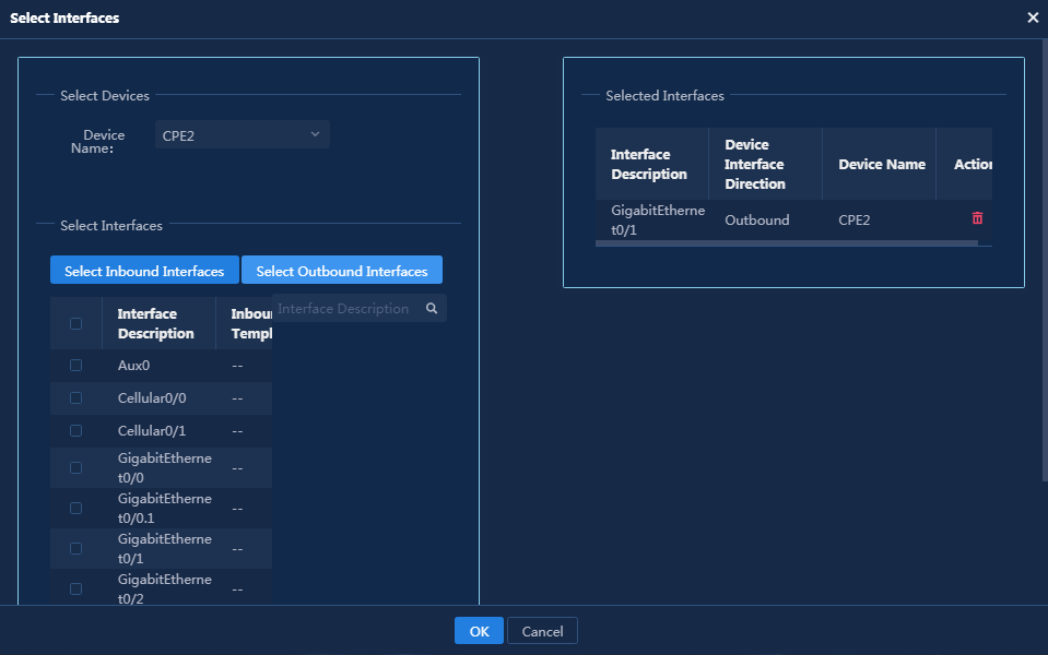
2. After interfaces are selected, deploy them to the device, as shown in Figure 150.
Figure 150 Deployment was successful
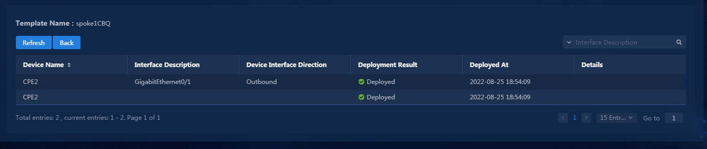
Configure application assurance templates on HQ devices (tunnel interfaces applications)
To configure an application assurance template on the tunnel interface, you must first configure a parent policy for rate limit based on branch egress bandwidth, and then use the sub-policy of the application assurance template.
1. Configure a traffic classifier. Click Add. In the dialog box that opens, select sdwanTte for Match Type. For example, configure traffic classifier for Spoke1 on the Layer 3 leased line TTE, as shown in Figure 151.
Figure 151 Creating a traffic classifier
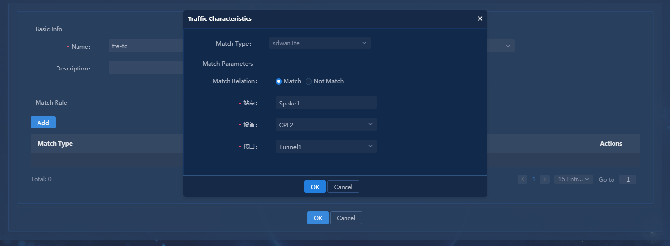
2. Create the traffic behavior of TTE rate limit. Click Add. Configure the committed information rate (CIR) in the GTS area (for example, set it to 3000 Kbps). Configure the sub-policy in the Traffic Policy area and specify the policy name (for example, Qosqueue), as shown in Figure 152.
Figure 152 Creating a traffic behavior
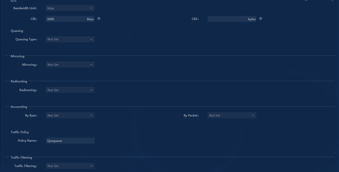
3. Create a traffic policy as shown in Figure 153.
Figure 153 Creating a traffic policy
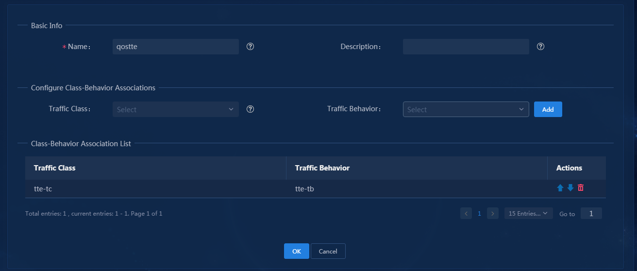
4. Click the ![]() icon for a
traffic policy in the Actions column to deploy the policy to outbound
tunnel interface of the Layer 3 leased line of HQ hub. Take Tunnel5 as
an example, as shown in Figure 154. If
the deployment succeeds, the page as shown in Figure 155 is
displayed.
icon for a
traffic policy in the Actions column to deploy the policy to outbound
tunnel interface of the Layer 3 leased line of HQ hub. Take Tunnel5 as
an example, as shown in Figure 154. If
the deployment succeeds, the page as shown in Figure 155 is
displayed.
Figure 154 Selecting deployment interfaces
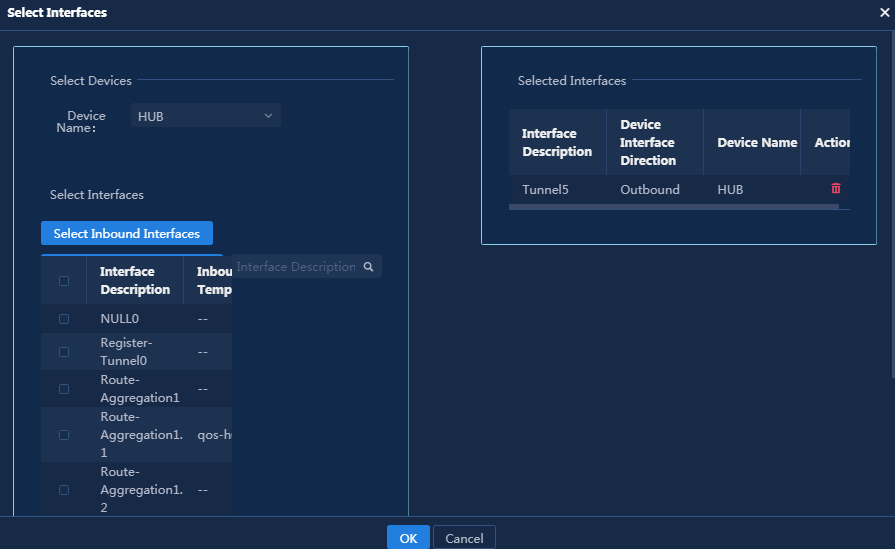
Figure 155 Deployment was successful
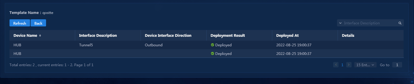
|
|
CAUTION: · Typically, the bandwidth of a WAN interface is lower than the bandwidth of a physical interface. You must limit rate for the WAN interface and configure application assurance for the interface. · Configure absolute bandwidth values to make sure the total bandwidth of all application assurance queues does not exceed the bandwidth of the link output interface. As a best practice to prevent traffic in assurance queues from occupying all interface bandwidth, make sure the bandwidth sum of all application assurance queues does exceed 80% of the actual interface bandwidth. · By default, the maximum bandwidth reserved on an interface is 80% of the total bandwidth. When you specify bandwidth ratios for application assurance queues, the bandwidth used for application assurance is calculated by using the following formula for each queue: Effective bandwidth used for application assurance = link total bandwidth × 80% × application bandwidth ratio. You can change the default reserved bandwidth on an interface by using the qos reserved-bandwidth pct percent command. As a best practice, do not change the default reserved bandwidth. |
Verify the configuration
1. Perform a simulation to send application traffic app1 and app2 (2000 Kbps for each) and the traffic rate exceeds the upper limit (3000 Kbps) for the links. On the receiver, verify that the application assurance settings can take effect. The settings can guarantee the minimum bandwidth required for the traffic of each application.
2. Query the WAN interface configuration on the device and verify that the application assurance settings have been deployed to the device.
<hub>dis qos policy interface Tunnel 5 outbound
Interface: Tunnel5
Direction: Outbound
Policy: qostte
Classifier: default-class
Matched : 44621 (Packets) 4165521 (Bytes)
5-minute statistics:
Forwarded: 7/5778 (pps/bps)
Dropped : 0/0 (pps/bps)
Operator: AND
Rule(s) :
If-match any
Behavior: be
-none-
Classifier: tte-tc
Matched : 22429 (Packets) 22922438 (Bytes)
5-minute statistics:
Forwarded: 61/498817 (pps/bps)
Dropped : 13/112447 (pps/bps)
Operator: OR
Rule(s) :
If-match sdwan-tte site-id 2 device-id 1 interface-id 2
Behavior: tte-tb
General Traffic Shaping:
CIR 3000 (kbps), CBS 187500 (Bytes), EBS 0 (Bytes)
Queue length: 50 (Packets)
Queue size : 0 (Packets)
Passed : 18303 (Packets) 17973546 (Bytes)
Discarded: 4126 (Packets) 4051732 (Bytes)
Delayed : 14935 (Packets) 14666170 (Bytes)
Nest Policy: Qosqueue
Classifier: default-class
Matched : 22429 (Packets) 22922438 (Bytes)
5-minute statistics:
Forwarded: 61/498817 (pps/bps)
Dropped : 13/112447 (pps/bps)
Operator: AND
Rule(s) :
If-match any
Behavior: be
-none-
<spoke1>dis qos policy interface GigabitEthernet 0/1 outbound
Interface: GigabitEthernet0/1
Direction: Outbound
Policy: Qosqueue
Classifier: default-class
Matched : 56450 (Packets) 12343104 (Bytes)
5-minute statistics:
Forwarded: 6/11030 (pps/bps)
Dropped : 0/0 (pps/bps)
Operator: AND
Rule(s) :
If-match any
Behavior: be
Default Queue:
Flow based Weighted Fair Queue:
Max number of hashed queues: 256
Matched : 0 (Packets) 0 (Bytes)
Enqueued : 0 (Packets) 0 (Bytes)
Discarded: 0 (Packets) 0 (Bytes)
Discard Method: Tail
Classifier: app1-dscp50
Matched : 0 (Packets) 0 (Bytes)
5-minute statistics:
Forwarded: 0/0 (pps/bps)
Dropped : 0/0 (pps/bps)
Operator: OR
Rule(s) :
If-match dscp 50
If-match tunnel-dscp 50
Behavior: app1-af
Assured Forwarding:
Bandwidth 1600 (kbps)
Matched : 0 (Packets) 0 (Bytes)
Enqueued : 0 (Packets) 0 (Bytes)
Discarded: 0 (Packets) 0 (Bytes)
Discard Method: Tail
Classifier: app2-dscp40
Matched : 0 (Packets) 0 (Bytes)
5-minute statistics:
Forwarded: 0/0 (pps/bps)
Dropped : 0/0 (pps/bps)
Operator: OR
Rule(s) :
If-match dscp cs5
If-match tunnel-dscp cs5
Behavior: app2-ef
Expedited Forwarding:
Bandwidth 1400 (kbps) CBS 35000 (Bytes)
Matched : 0 (Packets) 0 (Bytes)
Enqueued : 0 (Packets) 0 (Bytes)
Discarded: 0 (Packets) 0 (Bytes)
Application blocking
Configure the traffic behavior deny for the application traffic that matches the traffic classifier, so that the traffic forwarding is denied. This section takes as an example of how to deny the forwarding of app1 traffic on spoke1.
Configure application blocking templates via QoS management
1. Create a traffic classifier and match the ACL template of app1 to create a traffic classifier named app1-new, as shown in Figure 156. For specific configuration steps, see "Configure QoS management traffic policy."
Figure 156 Creating a traffic classifier
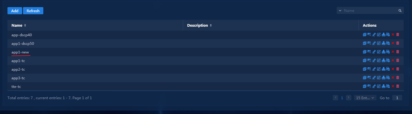
2. Create a traffic behavior and select deny for Traffic Filtering, as shown in Figure 157.
Figure 157 Creating a traffic behavior
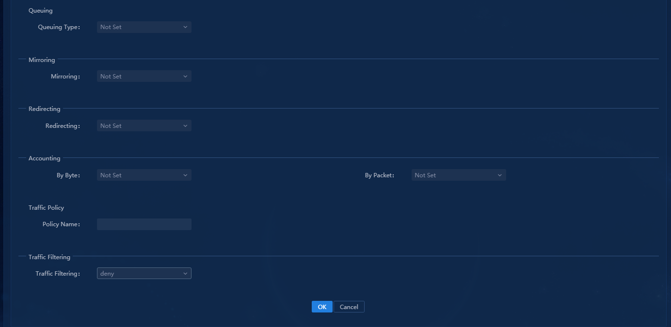
3. Create a traffic policy and associate the
traffic classifier with the traffic behavior. In this
example, the template has been applied to the LAN interface of spoke1. To
edit the global template and device template of the traffic policy, click the ![]() icon
in the Actions column, as shown in Figure 158. To
adjust the sequence, click the
icon
in the Actions column, as shown in Figure 158. To
adjust the sequence, click the ![]() icon. If no
template has been configured, you can add a traffic policy template.
icon. If no
template has been configured, you can add a traffic policy template.
Figure 158 Creating a traffic policy
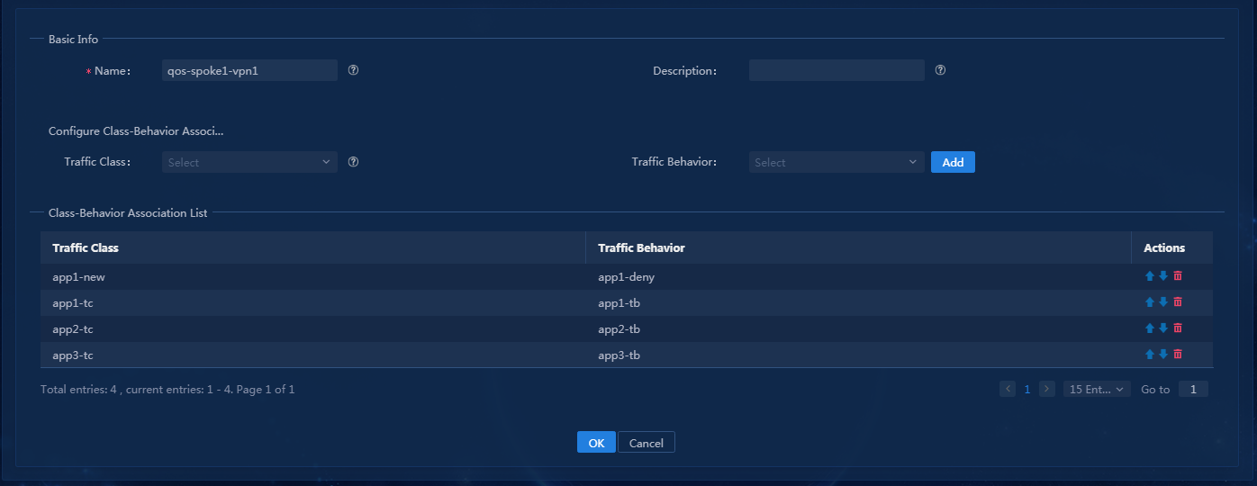
4. Click OK, as shown in Figure 159.
Figure 159 Deployment was successful
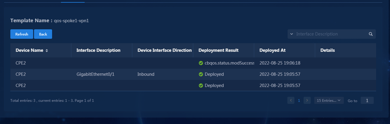
Verify the configuration
1. Perform a simulation to send traffic from app1 and forward the traffic by using spoke1. If the traffic is blocked, application blocking is successfully deployed.
2. Check the interface configuration on the device and verify that the configuration has been deployed.
<spoke1>dis qos policy interface GigabitEthernet 0/0.1 inbound
Interface: GigabitEthernet0/0.1
Direction: Inbound
Policy: qos-spoke1-vpn1
Classifier: default-class
Matched : 0 (Packets) 0 (Bytes)
5-minute statistics:
Forwarded: 0/0 (pps/bps)
Dropped : 0/0 (pps/bps)
Operator: AND
Rule(s) :
If-match any
Behavior: be
-none-
Classifier: app1-new
Matched : 62881 (Packets) 62629476 (Bytes)
5-minute statistics:
Forwarded: 0/0 (pps/bps)
Dropped : 188/1498635 (pps/bps)
Operator: OR
Rule(s) :
If-match acl name app1
Behavior: app1-deny
Filter enable: Deny
Classifier: app1-tc
Matched : 0 (Packets) 0 (Bytes)
5-minute statistics:
Forwarded: 0/0 (pps/bps)
Dropped : 0/0 (pps/bps)
Operator: OR
Rule(s) :
If-match acl name app1
Behavior: app1-tb
Marking:
Remark dscp 50
Remark tunnel-dscp 50
Remark flow-id 100
Classifier: app2-tc
Matched : 0 (Packets) 0 (Bytes)
5-minute statistics:
Forwarded: 0/0 (pps/bps)
Dropped : 0/0 (pps/bps)
Operator: OR
Rule(s) :
If-match acl name app2
Behavior: app2-tb
Marking:
Remark dscp cs5
Remark flow-id 200
Remark tunnel-dscp cs5
Classifier: app3-tc
Matched : 0 (Packets) 0 (Bytes)
5-minute statistics:
Forwarded: 0/0 (pps/bps)
Dropped : 0/0 (pps/bps)
Operator: OR
Rule(s) :
If-match acl name app3
Behavior: app3-tb
Marking:
Remark flow-id 101
Basic and extended O&M features
The O&M and visibility features are relatively independent of each other. Choose the topics for the features as needed. The prerequisites for the features are described in their respective feature overview.
Homepage
1. Use a tenant service administrator account (sdwan1) to log in to Unified Platform. Figure 160 shows the homepage information for the tenant, which provides 10 widgets by default. You can edit the map settings and configure device locations on the tenant homepage.
2. If you use the default administrator account to log in, you can also edit the widgets to be displayed on the homepage.
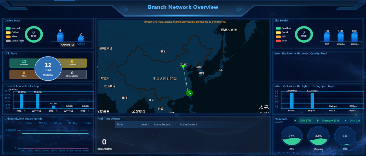
You can click each widget to drill down to the corresponding configuration page. For example, clicking the Link Bandwidth Usage Trends widget in the left lower corner of the page will open the link running status page, as shown in Figure 161.
Figure 161 Links running status
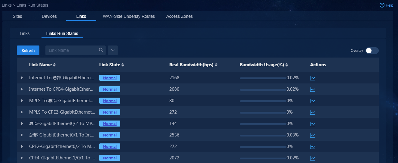
Edit homepage map settings and configure device locations
1. Use a tenant service administrator account (sdwan1) to log in to Unified Platform. Navigate to the Automation > Branch Network > Parameter Settings > O&M Settings > Map Settings page, as shown in Figure 162. On this page, you can configure the regions and links to be displayed on the map on the tenant homepage.
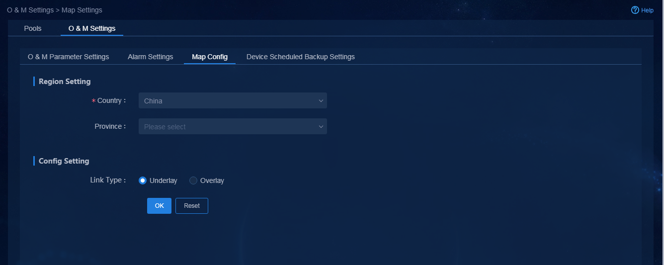
Parameters:
¡ Region Setting: Configure the regional map to be displayed on the homepage. For example, if you select the country China without selecting a province, the homepage will display the whole map of China.
¡ Link Type: Select whether to display underlay or overlay links. This example selects Underlay.
2. When you import sites and devices, you can
import the site location information. For more information, see "Import sites and devices." You can also edit device location information after devices
are added or imported. Navigate to the Automation > Branch Network
> Physical Network > Sites > Sites page. On this
page, you can view the site
list. To edit the location of a device, select the device and then click the ![]() icon
in the Actions column, as shown in Figure 163.
icon
in the Actions column, as shown in Figure 163.
Figure 163 Relocating a device

3. To display underlay links, you must also configure
location information for virtual cloud nodes. Navigate to the Automation
> Branch Network > Virtual Network > vNetwork
Deployment page. On this page, you can edit location information for an
L3VPN or Internet network. Click the ![]() icon to edit the
location information, as shown in Figure 164.
icon to edit the
location information, as shown in Figure 164.
Figure 164 Relocating a device

Edit the widgets to be displayed on the tenant homepage
1. Use the system administrator account (admin) to log in to Unified Platform. Hover over the system icon in the top left corner to display all menus, as shown in Figure 165.
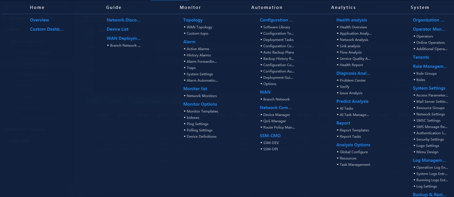
2. Select Custom Dashboard to open the dashboard editor, as shown in Figure 166.
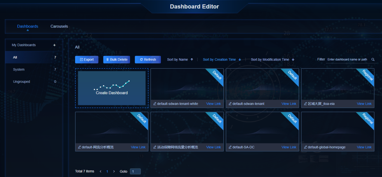
3. Select default-sdwan-tenant, and then click the Edit icon to open the tenant dashboard editing page, as shown in Figure 167.
Figure 167 Editing tenant dashboard
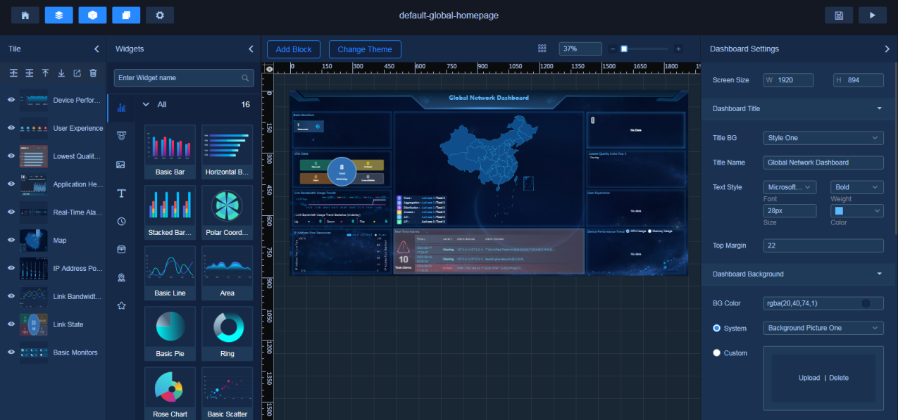
4. Customize the dashboard as needed, and then click the Save icon.
Edit the homepage map display mode
1. Log in to Unified Platform as the default system administrator (admin). Edit the widget on the tenant homepage to change the map display mode. By default, the controller uses GIS map, as shown in Figure 168.
Figure 168 GIS map configuration
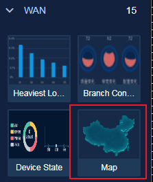
2. Change the map display mode to static, as shown in Figure 169.
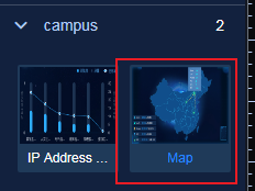
|
|
CAUTION: · Switching the map display mode is a global setting and can only be performed by the default system administrator. All tenants use the same map display mode. · To use a GIS map, make sure the PC used to access the controller can access the Internet and the Baidu website. |
Basic visibility features
After services are deployed, the controller provides the following basic visibility features:
· Topology visualization and management—Allows you to query the controller topology, query devices, links, and application paths on the topology, and add or delete devices on the topology.
· Device visualization and editing—Provides a device list where you can query the device status, including the device module status and interface status.
· Link visualization and management—Provides an underlay link list and an overlay link list, where you can query the basic and historical information of the links and the real-time link operation status.
· Site visualization—Provides site-based topology and related information.
Topology visualization and management
Use a tenant service administrator account (sdwan1) to log in to Unified Platform. Navigate to the Monitor > Topology > Branch Topology page. On this page, you can view topology information, move devices, or edit the topology, as shown in Figure 170.
Figure 170 Topology management
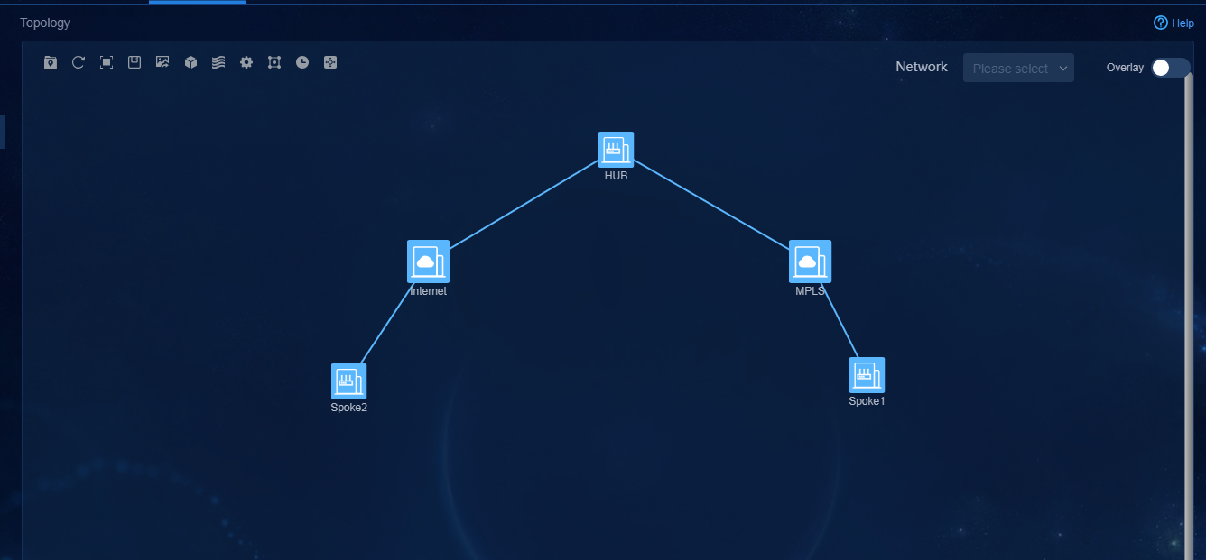
The topology page provides the following primary operations (common operations such as zoom in and out are not described):
1. Site Group ![]() : Add sites of the same tier to a group. For
example, add Site2 and Site3 to a group named Branch, as shown in Figure 171 and Figure 172.
: Add sites of the same tier to a group. For
example, add Site2 and Site3 to a group named Branch, as shown in Figure 171 and Figure 172.
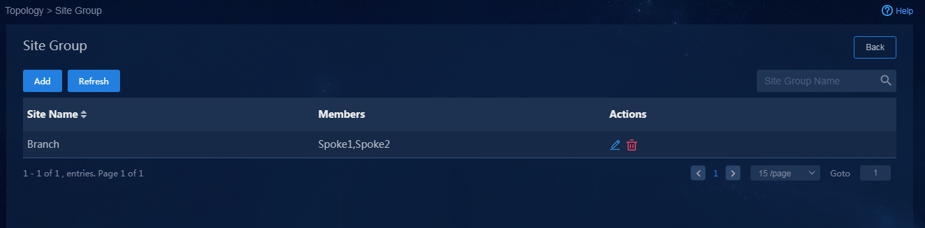
Figure 172 Site group topology
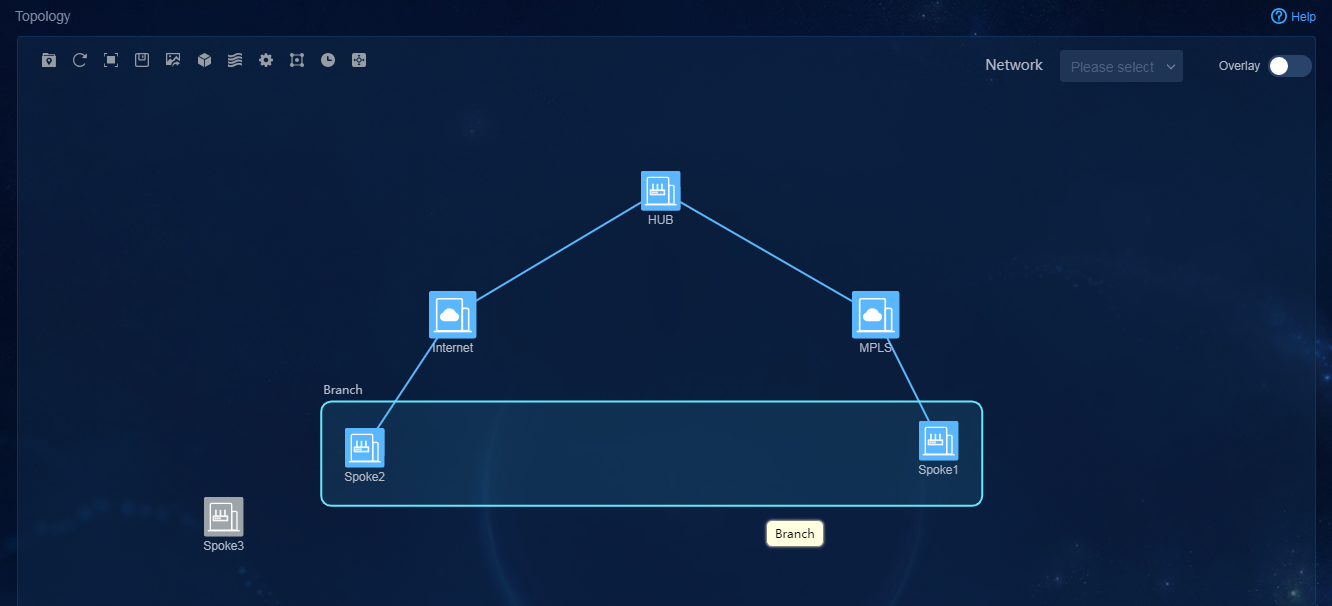
2. Application Group ![]() : Query the forwarding paths of application groups. For more
information, see "Verify the "
in "Configure QoS application
assurance."
: Query the forwarding paths of application groups. For more
information, see "Verify the "
in "Configure QoS application
assurance."
3. Link Traffic Summary
![]() : Display Top N links by history traffic and real-time traffic. You
can select the link type Underlay or Overlay. For history
traffic, you can also choose the time range to be displayed, as shown in Figure 173.
: Display Top N links by history traffic and real-time traffic. You
can select the link type Underlay or Overlay. For history
traffic, you can also choose the time range to be displayed, as shown in Figure 173.
Figure 173 Top N links by traffic
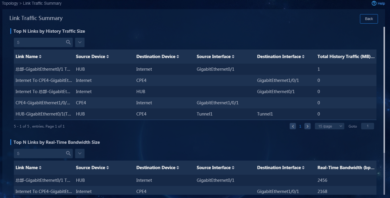
4. Locate Node ![]() :
Search for a specific node. The found node is identified in a red box, as shown
in Figure 174.
:
Search for a specific node. The found node is identified in a red box, as shown
in Figure 174.
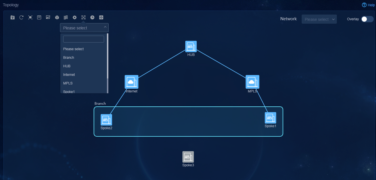
5. Service Network ![]() : Select a service network, and the topology displays only the
devices and links in the network, as shown in Figure 175.
: Select a service network, and the topology displays only the
devices and links in the network, as shown in Figure 175.
Figure 175 Internet service network
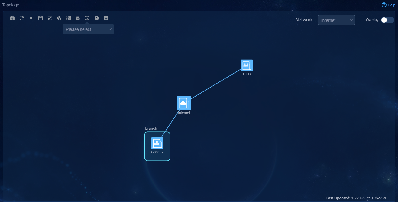
6. Overlay and Underlay Switching ![]() : Choose to display the Overlay or Underlay
topology.
: Choose to display the Overlay or Underlay
topology.
7. Click a device on the topology page. The
device information is displayed, as shown in Figure 176. If
the device has alarms, you can click the ![]() icon in the Actions
column to view the alarm details.
icon in the Actions
column to view the alarm details.
Figure 176 Viewing device information
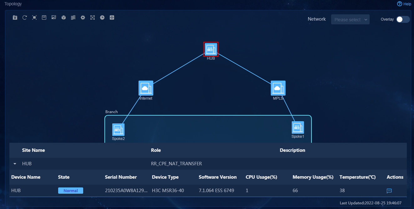
8. Click a link on the topology page. The link
information is displayed, as shown in Figure 177. To
view the history link information, click the icon in the Actions column.
If the link has alarms, click the ![]() icon in the Actions
column, and then you can also view the alarm details.
icon in the Actions
column, and then you can also view the alarm details.
Figure 177 Viewing device information
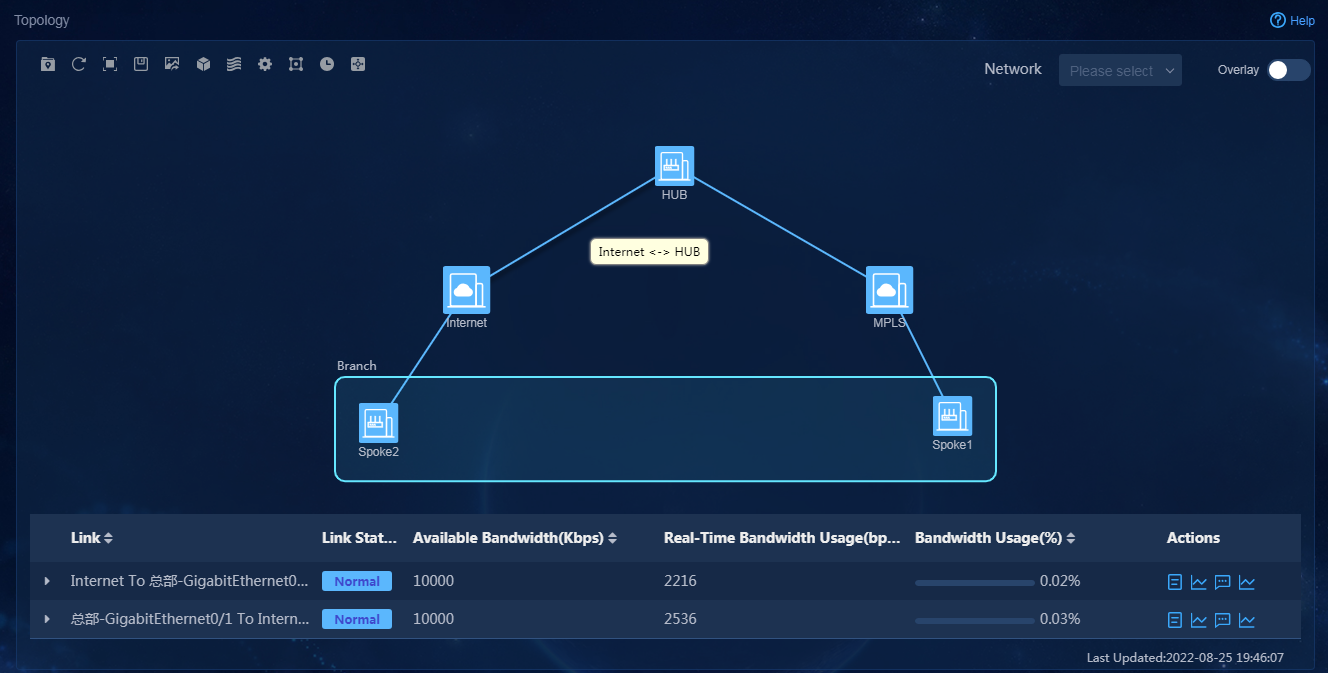
9. Right-click the blank space on the topology page to add sites.
10. Right-click the site to view site details, add a site or delete a site.
Device visualization and management
1. Use a tenant service administrator account (sdwan1) to log in to Unified Platform. Navigate to the Automation > Branch Network > Physical Network > Devices > Devices page. On this page, you can view the device list, as shown in Figure 178. On the device list, you can perform the following tasks:
¡ Edit device locations. For configuration procedures, see "Edit homepage map settings and configure device locations."
¡ Upgrade device versions. For configuration procedures, see "Device software upgrade.
¡ Back up device configuration and replace devices. For configuration procedures, see "Backup restoration and replacement."
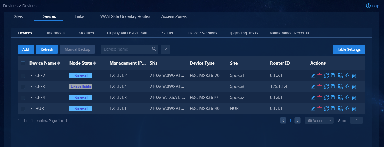
2. Click the Interfaces tab. Select a device to display the interface list for the device, as shown in Figure 179. You can view interface status and edit the description of an interface.
Figure 179 Interface management
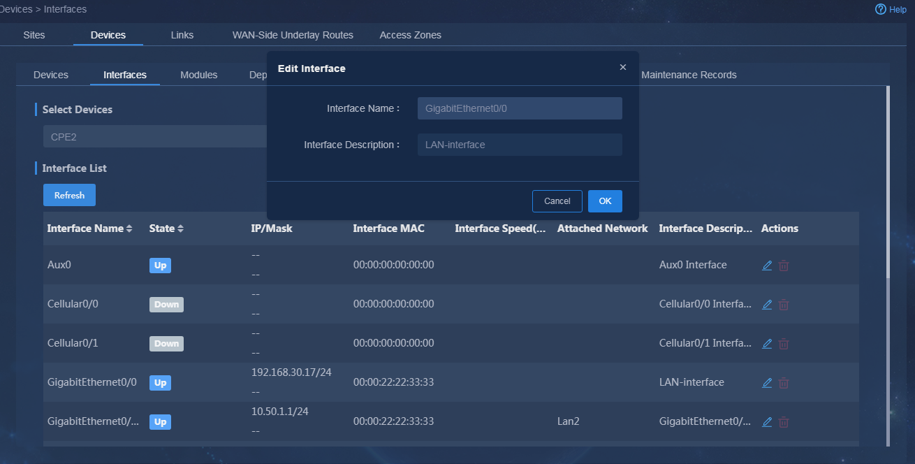
3. Click the Modules tab. Select a device and then you can view the module status of the device. If a module is abnormal, you can click the icon in the Actions column to verify the module or submodule status, as shown in Figure 180.
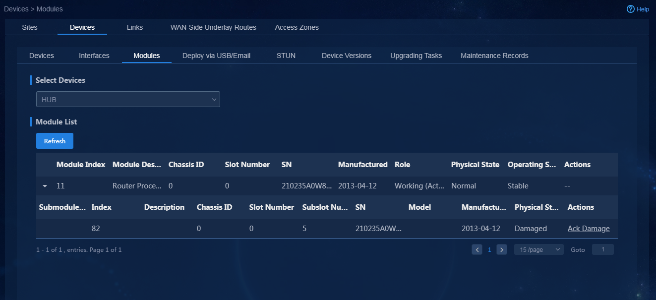
|
|
CAUTION: · If a module is removed from a device, the device generates an alarm. To clear the alarm, you must confirm the removal of the module on this page. · If a module is damaged or removed, the controller does not save the configuration automatically. Please process the module anomaly as soon as possible to avoid configuration loss. · If a module will not be used any longer, you can click Absent Confirmed. Then, the module-related service configuration data, submodule and interface information (such as LAN/WAN network details and rate limit settings) at the controller side will be cleared and cannot be restored. Use the clearing operation with caution. |
Link visualization and management
1. Use a tenant service administrator account (sdwan1)
to log in to Unified Platform. Navigate to the Automation > Branch
Network > Physical Network > Links > Links
page. On this page, you can view the link list, as shown in Figure 181. You
can choose to display underlay or overlay links. In the Actions column,
you can click the Edit icon ![]() to edit the
available bandwidth for an underlay link.
to edit the
available bandwidth for an underlay link.
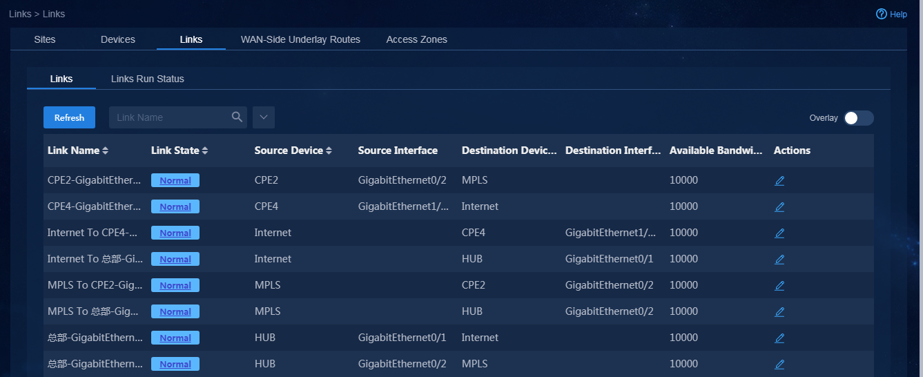
2. Click the Links Run Status tab. The
real-time running status of links is displayed, as shown in Figure 182. Click
the ![]() icon to view history information for a link. On the overlay link
list, you can also view application
traffic information, as shown in Figure 183.
icon to view history information for a link. On the overlay link
list, you can also view application
traffic information, as shown in Figure 183.
Figure 182 Links running status
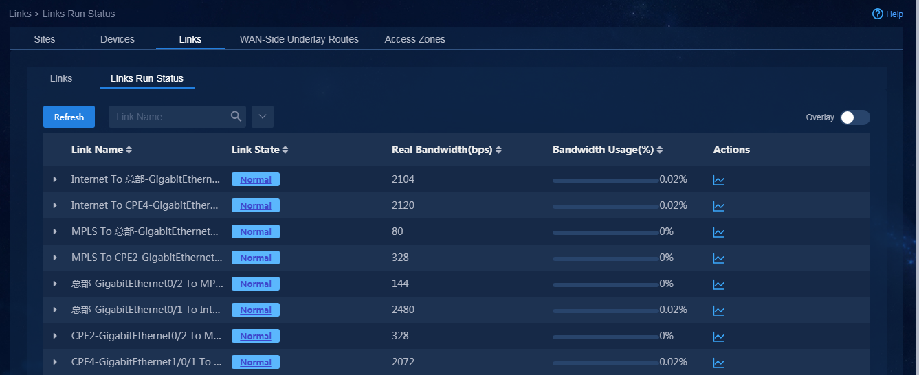
Figure 183 Link history information
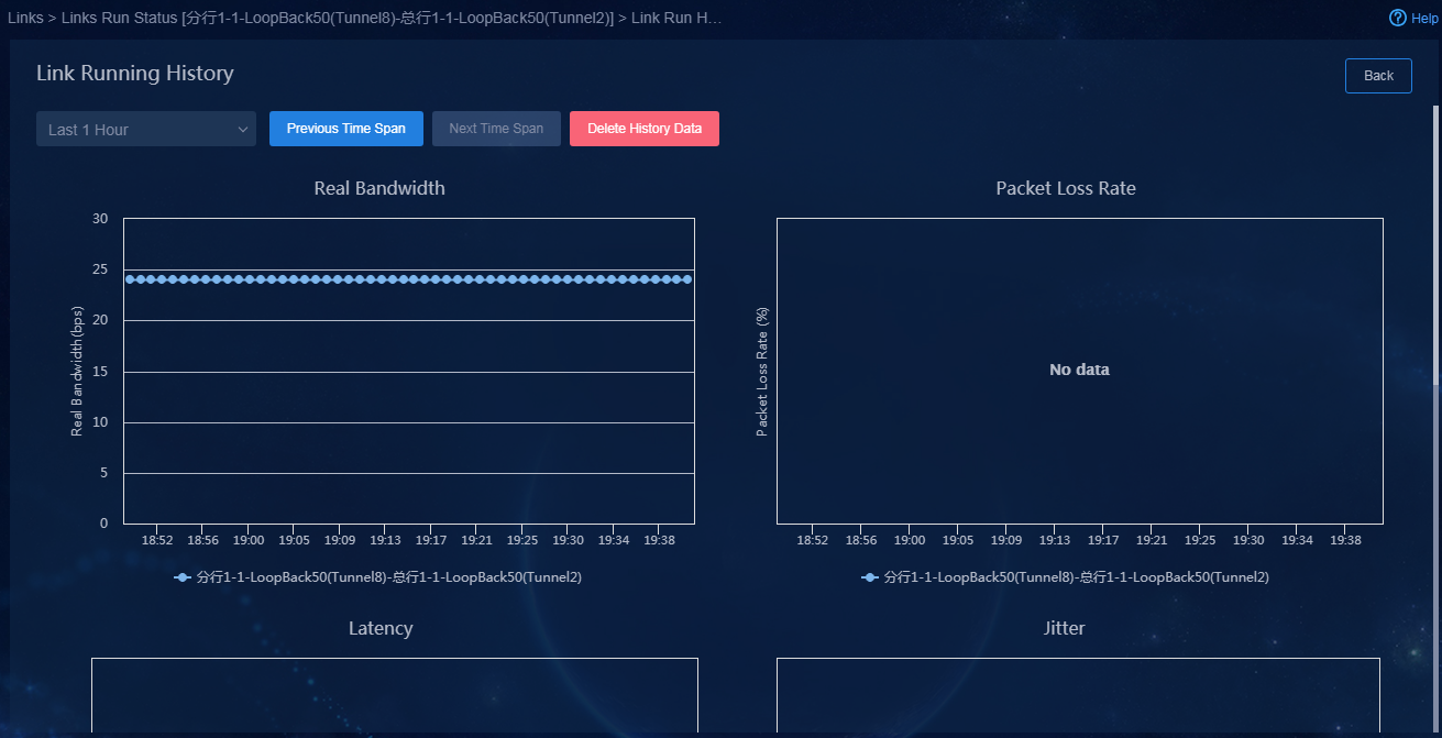
|
|
CAUTION: The underlay link quality is evaluated based on the overlay tunnel quality probe result. The quality of an underlay link is the quality of the optimal overlay tunnel that uses the underlay link. Before overlay tunnels are deployed, underlay link quality information cannot be displayed. |
Site visualization
1. Use a tenant service administrator account (sdwan1) to log in to Unified Platform. Navigate to the Automation > Branch Network > Physical Network > Sites > Sites page. On this page, you can view the site list, as shown in Figure 184.
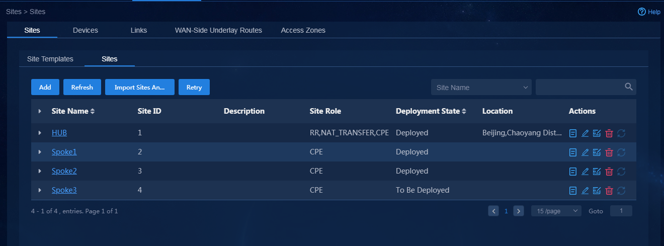
2. Click the ![]() icon in the Actions
column for a site to view details of the site, as shown in Figure 185. On
the site details page, you can view the site's basic information, the
performance information for the
devices, and the information for tunnels, links, applications, and alarms in the site. The topology
in the middle of the page displays all the interconnected links of the site.
icon in the Actions
column for a site to view details of the site, as shown in Figure 185. On
the site details page, you can view the site's basic information, the
performance information for the
devices, and the information for tunnels, links, applications, and alarms in the site. The topology
in the middle of the page displays all the interconnected links of the site.

Alarm settings
Alarm settings
You can configure the alarms generated by the controller, including the link alarm configuration, alarm suppression, and alarm threshold settings.
Use a tenant service administrator account (sdwan1) to log in to Unified Platform. Navigate to the Automation > Branch Network > Parameter Settings > O & M Settings > Alarm Settings page.
· Link alarm settings: Turn on or turn off the alarms for underlay and overlay links, as shown in Figure 186.
Figure 186 Link alarm settings
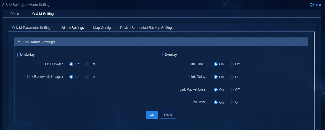
· Alarm suppression: Configure alarm suppression settings. After alarm suppression is enabled, the system can suppress alarms to reduce the number of alarms to be sent, as shown in Figure 187.
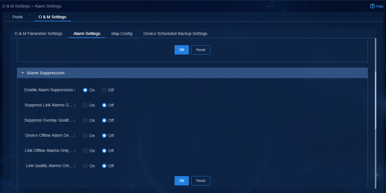
Parameters:
¡ Suppress Link Alarms Generated upon Device Offline: With the suppression interval configured, the system does not immediately send link down alarms generated upon device offline but waits for the alarm suppression interval.
¡ Device Offline Alarm Delay: The controller does not send a device offline alarm if the device restores its state within 1 minute after a device offline event. If the device fails to restore its online state in 1 minute, the controller sends the device offline alarm.
· Alarm threshold triggers: Configure the alarm thresholds, including the alarm triggers, as shown in Figure 188.
Figure 188 Alarm threshold triggers
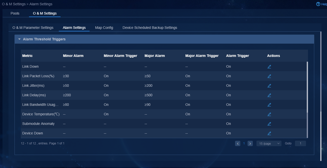
Manage alarms
After alarm settings are configured, you can view alarms generated in case of network anomalies.
Active alarms
Use a tenant service administrator account (sdwan1) to log in to Unified Platform. Navigate to the Monitor > Alarm > Active Alarms page. By default, the active alarms generated in the last 30 days are displayed. After an alarm is cleared, it will not be immediately moved to the history alarm list. All the alarms cleared at a day will be moved to the history alarm list at 24:00 that day, as shown in Figure 189.
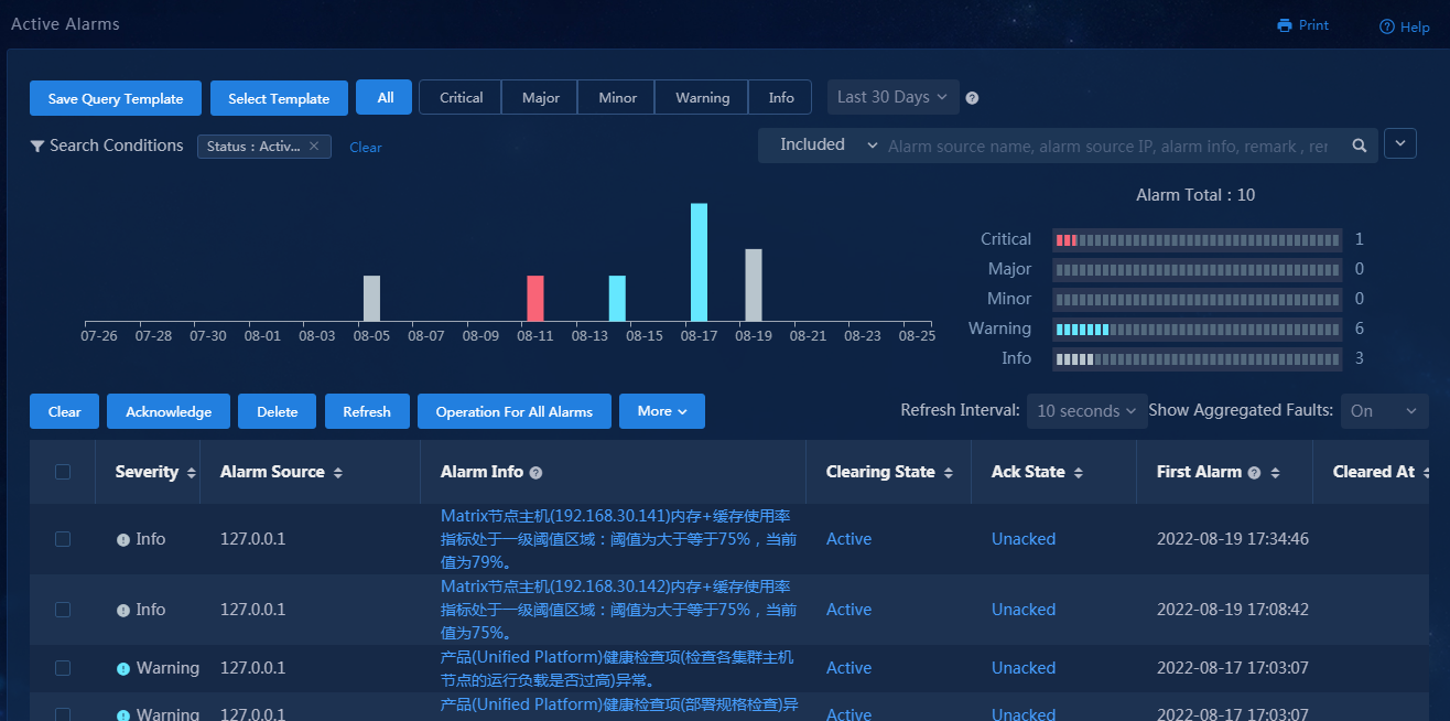
History alarms
Use a tenant service administrator account (sdwan1) to log in to Unified Platform. Navigate to the Monitor > Alarm > History Alarms page. By default, the alarms recovered in the last 3 days are displayed, as shown in Figure 190.
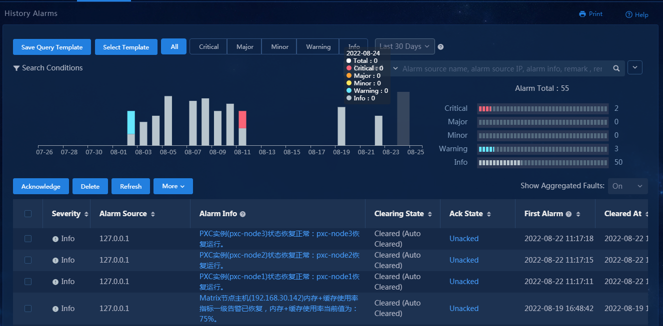
Alarm forwarding
Use a tenant service administrator account (sdwan1) to log in to Unified Platform. Navigate to the Monitor > Alarm > Alarm Forwarding Rules page. On this page, you can configure alarm forwarding rules. Alarms can be forwarded through emails, SMS messages, and WeChat messages. Click Add to add an alarm forwarding rule, as shown in Figure 191.
Figure 191 Adding an alarm forwarding rule
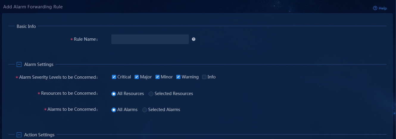
Trap management
Use a tenant service administrator account (sdwan1) to log in to Unified Platform. Navigate to the Monitor > Alarm > Trap Management page. This page includes the following four submenus.
· Trap List: You can view all traps received by Unified Platform. Unified Platform receives trap messages and generates alarms accordingly. The alarms generated by the SeerEngine-SDWAN controller are also sent to Unified Platform through trap messages.
· Trap Definitions:
Each trap has a predefined alarm severity. You can edit the severity of a trap.
You can view trap information
based on the trap name and OID. To edit the information of a trap, click the Edit
icon ![]() in the Actions column. For example, you can change the
severity of the link packet loss rate major alarm to Warning, as shown
in Figure 192.
in the Actions column. For example, you can change the
severity of the link packet loss rate major alarm to Warning, as shown
in Figure 192.
Figure 192 Changing trap severity
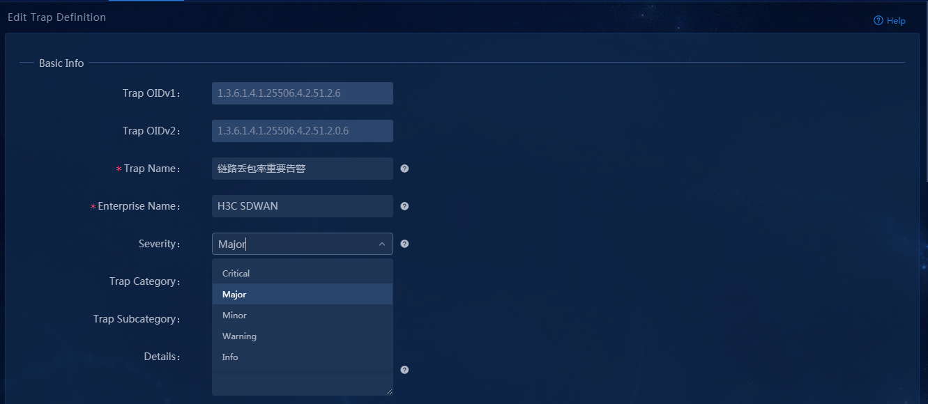
· Trap Filter Rules: Filter duplicate alarms according to the configured rules.
· Trap-to-Alarm Rules: After Unified Platform receives traps, it upgrades the traps to alarms according to the trap-to-alarm rules. The system has predefined a large number of trap-to-alarm rules. You can enable or disable the predefined trap-to-alarm rules but you cannot delete them. You can search for specific trap-to-alarm rules and then switch the on/off status by clicking the status. Then, traps sent by SDWAN will not be escalated to alarms, as shown in Figure 193.
Figure 193 Trap-to-alarm rules
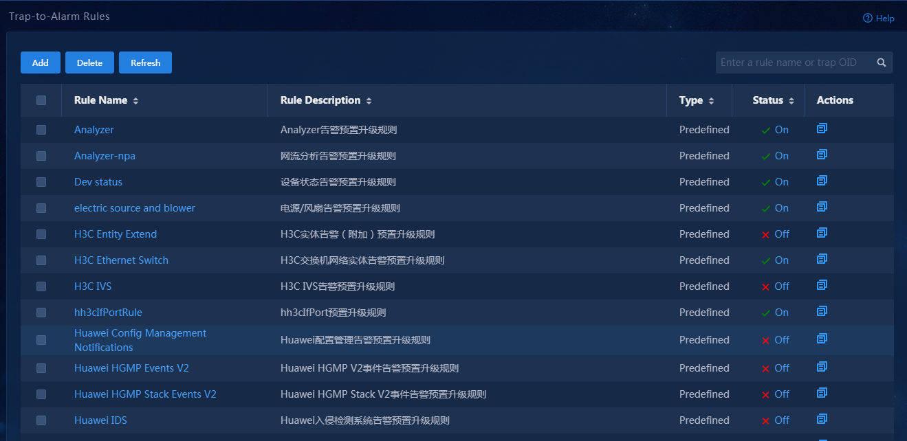
Controller log management
The controller can synchronize operation logs and system logs to the upper-level log server for users to implement unified O&M management.
When the controller becomes faulty, you can use the running logs and operation logs of the controller to troubleshoot the issue.
Operation logs
1. Log in to Unified Platform as the system administrator (admin).
2. Navigate to the System > Log Management > Operation Logs Entries page, as shown in Figure 194.
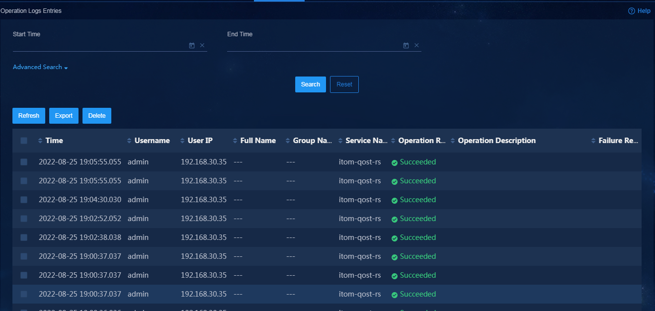
3. To edit operation log settings, navigate to the System > Log Management > Operation Logs Configuration page. On this page, you can edit the operation log settings and log server settings, as shown in Figure 195.
Figure 195 Operation log settings
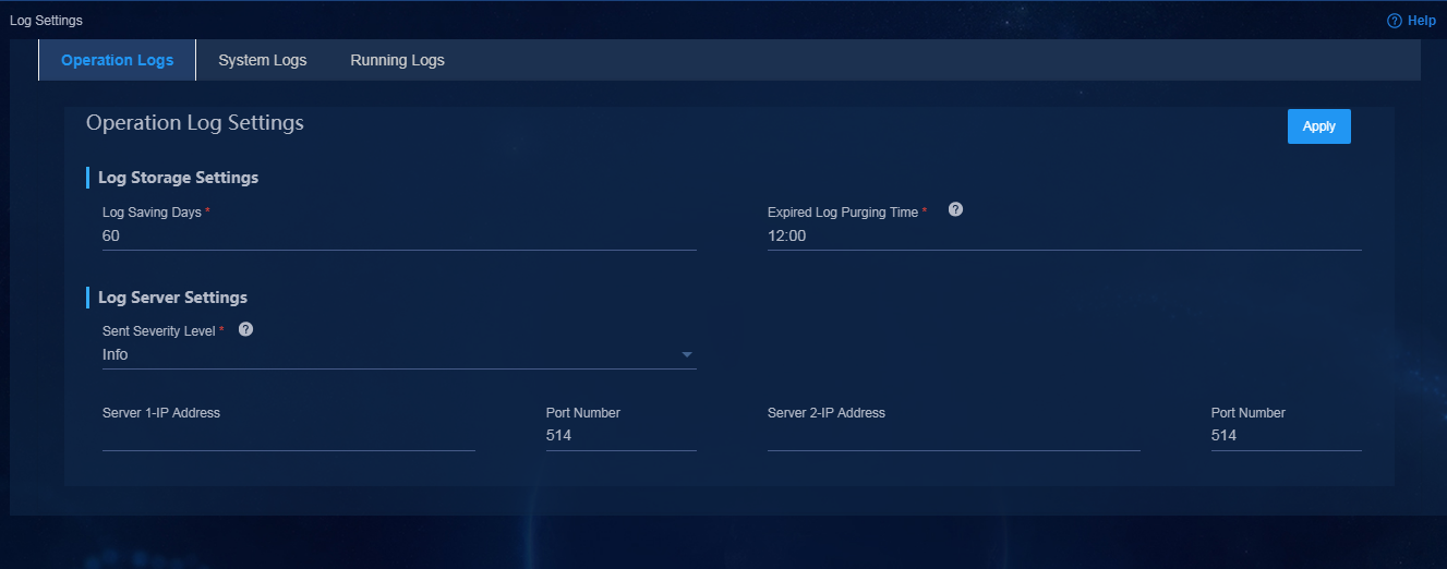
System logs
System logs contain all alarms.
1. Log in to Unified Platform as the system administrator (admin).
2. Navigate to the System > Log Management > System Logs Entries page. On this page, you can view system logs, as shown in Figure 196.

3. You can implement the alarm forwarding function through system log delivery. To edit system log settings, navigate to the System > Log Management > System Logs Configuration page, as shown in Figure 197.
Figure 197 System log settings
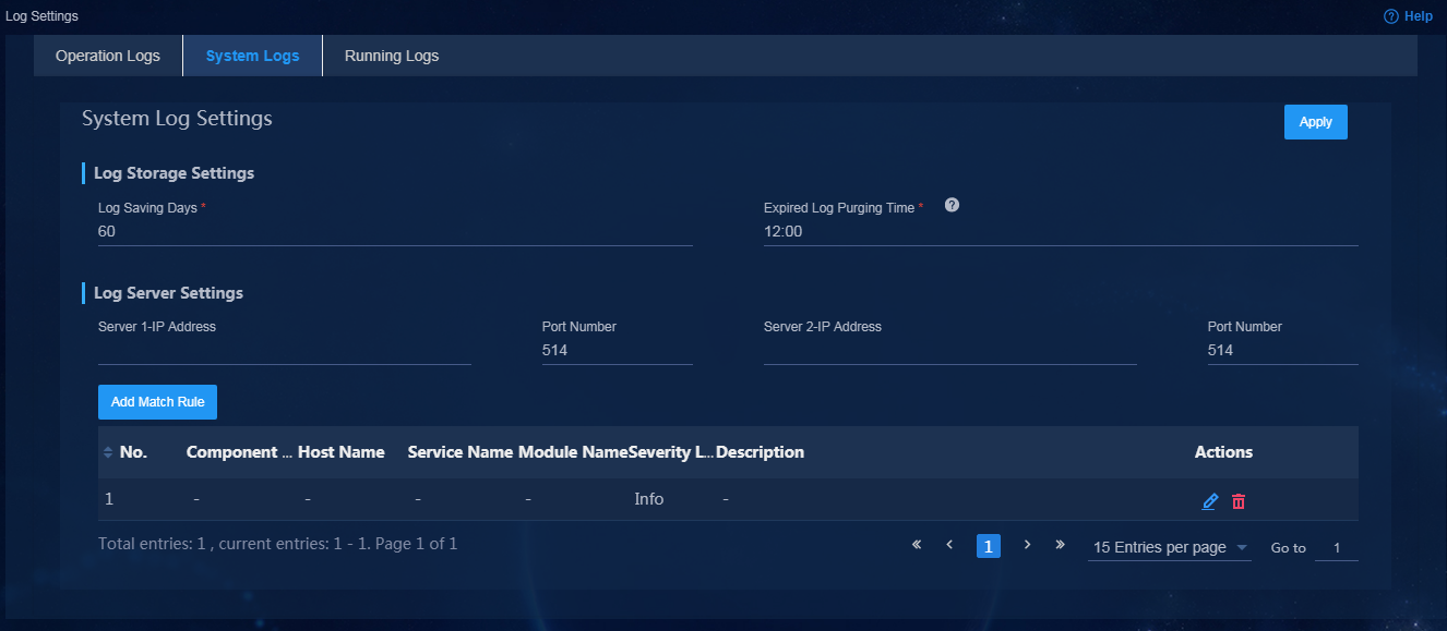
Running logs
The controller requires running logs for troubleshooting.
1. To view global running logs or logs for each node, log in to Unified Platform as the system administrator (admin).
2. Navigate to the System > Log Management > Running Logs Entries page, as shown in Figure 198.
3. Search for the logs based on the time when the problem occurred and the associated component. You can select all displayed logs and export them.
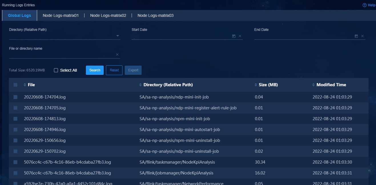
4. To edit running log settings, navigate to the System > Log Management > Running Logs Configuration page, as shown in Figure 199.
Figure 199 Running log settings
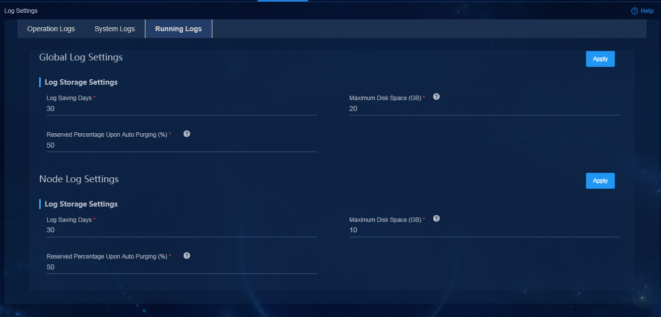
Role-based permission configuration
Configure permissions and domains
Role-based permission configuration enables users to manage or query various devices and application groups. Figure 200 shows the configuration workflow.
Figure 200 Configuration workflow
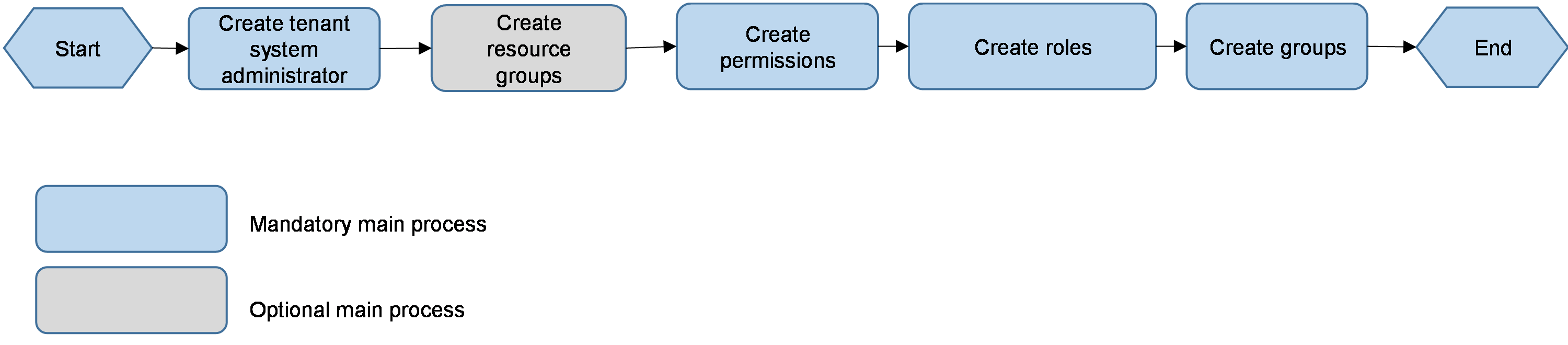
You must create an administrator for each service level. Table 9 shows the configuration requirements.
Table 9 Role-based permission configuration requirements
|
User |
Permissions |
Managed devices |
Remarks |
|
sdwan1 |
Service management permissions |
Hub, spoke1, spoke2, spoke3, spoke4 |
Manages and views all devices |
|
sdwan2 |
Service management permissions |
spoke1 and spoke2 |
Views two branch devices |
By default, sdwan1 can view all devices. For its configuration procedure, see "(Optional) Create a tenant service administrator." This section describes role-based permission configuration by taking the example of user sdwan2.
Create a tenant system administrator
1. Log in to Unified Platform as the default system administrator (admin).
2. Navigate to the System > Operator Management > Operators page. Click Add. Configure related parameters as shown in Figure 201.
3. In this example, specify operator name sdwan, select a tenant SDWAN, select System Manager Group as the role group, select Simple Password Authentication as the authentication mode, and set the login password to Pwd@12345.
Figure 201 Adding a system administrator
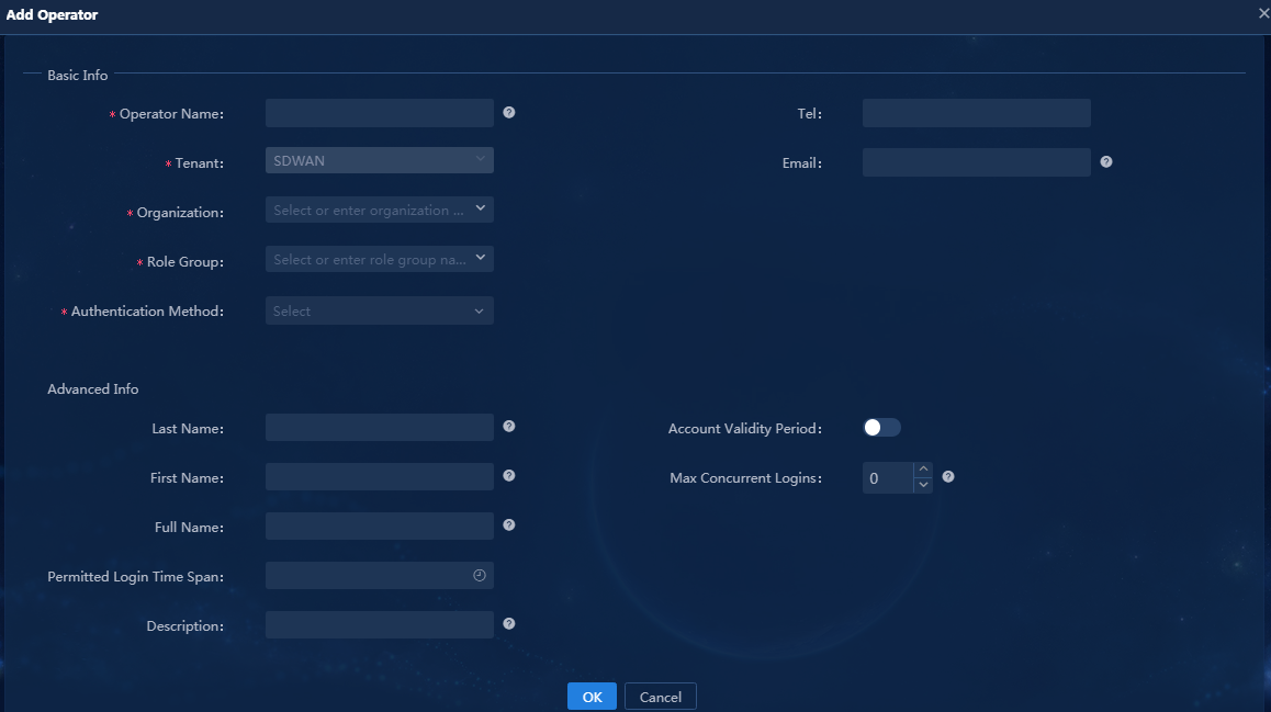
Create permissions
1. Log in to Unified Platform as the tenant system administrator (sdwan).
2. Navigate to the System > Permission Management > Roles > Permissions page. Click Add. Configure related parameters as shown in Figure 202.
3. In this example, enter sdwan2 for Permission Name. Select SDWAN for Permission Group, and Network Devices for Resource Type. Specify Manage Network Devices, View Network Devices, Edit Network Devices, Manage Interfaces, and View Interfaces as the actions. Select select for Select Scope, and select resources spoke1 and spoke2.
Figure 202 Creating permissions
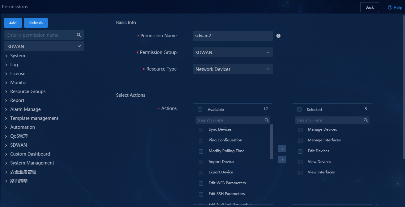
Create user roles
1. Log in to Unified Platform as the tenant system administrator (sdwan).
2. Navigate to the System > Permission Management > Roles page. Click Add. This section creates a role for user sdwan2 and selects permissions sdwan2, as shown in Figure 203.
Figure 203 Creating user roles
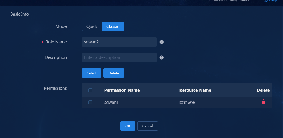
Create groups
1. Log in to Unified Platform as the tenant system administrator (sdwan).
2. Navigate to the System > Permission
Management > Groups page. Click Add. Click the ![]() icon
corresponding to the system manager group to create a group. In this example,
enter sdwan2 as the group name, copy the permissions of the system
manager group, and select sdwan2 for Roles (unselect Alarm
Manager and Network Device Manager), as shown in Figure 204. You
can also create a group and add roles as shown in Table 10.
icon
corresponding to the system manager group to create a group. In this example,
enter sdwan2 as the group name, copy the permissions of the system
manager group, and select sdwan2 for Roles (unselect Alarm
Manager and Network Device Manager), as shown in Figure 204. You
can also create a group and add roles as shown in Table 10.
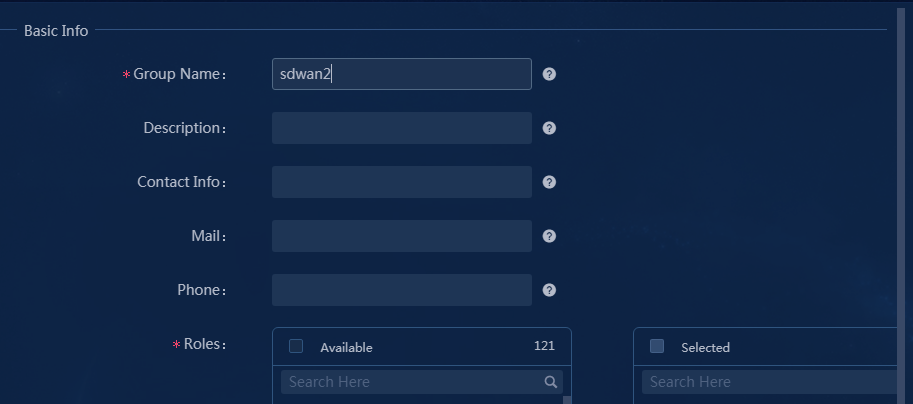
Table 10 Commonly used default branch roles
|
Role |
Description |
Required |
Remarks |
|
Branch system homepage viewer |
This role has the permissions to view the branch system homepage. |
No |
The service homepage is displayed on the dashboard. |
|
Branch system homepage manager |
This role has the permissions to manage the branch system homepage. |
No |
The service homepage is displayed on the dashboard. |
|
Branch service homepage viewer |
This role has the permissions to view the branch service homepage. |
No |
View permissions |
|
Branch service homepage manager |
This role has the permissions to manage the branch service homepage. |
Yes |
Management permissions |
|
Branch device onboarding plan viewer |
This role has the permissions to view branch device onboarding plans. |
No |
View permissions |
|
Branch device onboarding plan manager |
This role has the permissions to manage branch device onboarding plans. |
Yes |
Management permissions |
|
Branch network plan viewer |
This role has the permissions to view branch network plans. |
No |
View permissions |
|
Branch network plan manager |
This role has the permissions to manage branch network plans. |
Yes |
Management permissions |
|
Branch application TE setting viewer |
This role has the permissions to view branch application TE settings. |
No |
View permissions |
|
Branch application TE setting manager |
This role has the permissions to manager branch application TE settings. |
Yes |
Management permissions |
|
Branch topology viewer |
This role has the permissions to view branch topologies. |
No |
View permissions |
|
Branch topology manager |
This role has the permissions to manage branch topologies. |
Yes |
Management permissions |
|
Branch physical network viewer |
This role has the permissions to view branch physical networks. |
No |
This role has permissions on all devices. You cannot bind this role to branch physical networks that have already been assigned permissions. |
|
Branch physical network manager |
This role has the permissions to manage branch physical networks. |
No |
This role has permissions on all devices. You cannot bind this role to branch physical networks that have already been assigned permissions. |
|
Branch virtual network viewer |
This role has permissions to view branch virtual networks. |
No |
View permissions |
|
Branch virtual network manager |
This role has permissions to manage branch virtual networks. |
Yes |
Management permissions |
|
Branch tenant network viewer |
This role has permissions to view branch tenant networks. |
No |
View permissions |
|
Branch tenant network manager |
This role has permissions to manage branch tenant networks. |
Yes |
Management permissions |
|
Branch policy viewer |
This role has the permissions to view branch policies. |
No |
This role has permissions on all the policies. You cannot bind this role to branch policies that have already been assigned to a group. |
|
Branch policy manager |
This role has the permissions to manage branch policies. |
No |
This role has permissions on all the policies. You cannot bind this role to branch policies that have already been assigned to a group. |
|
Alarm manager |
An alarm manager that can perform operations on active alarms, history alarms, traps, trap definitions, trap filtering rules, trap-to-alarm rules, and alarm forwarding rules. |
Yes |
Support for alarm functions required. |
|
Resource group viewer |
A resource group viewer can view resource groups. |
No |
Custom roles already have the permissions to view resources. |
|
Resource group manager |
A resource group manager can configure resource groups. |
No |
Custom roles already have the permissions to view resources. |
|
|
CAUTION: · To assign devices to a group, you might create a branch physical network viewer or manager for binding specific resources. In this case, you cannot bind the default branch physical network viewer or manager when creating the group. · You must assign permissions for viewing resources to implement role-based permission management. You can bind associated permissions to a role upon creation of the role as described in this document, or use the default resource group viewer or manager role. · The system also provides other default roles. You can add the roles as needed. |
Create users
1. Log in to Unified Platform as the tenant system administrator (sdwan).
2. Navigate to the System > Operator Management > Operators page. Click Add. In this example, set Operator Name to sdwan2, Tenant to SDWAN, Organization to sdwan2, and Authentication Method to Simple Password Authentication, and set the authentication password, as shown in Figure 205.
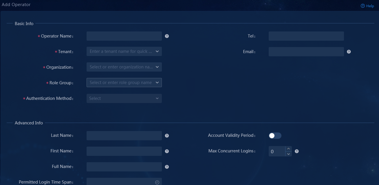
Verify the configuration
1. Log in to Unified Platform as user sdwan2 to view the homepage, as shown in Figure 206.
Figure 206 Dashboard for user sdwan2
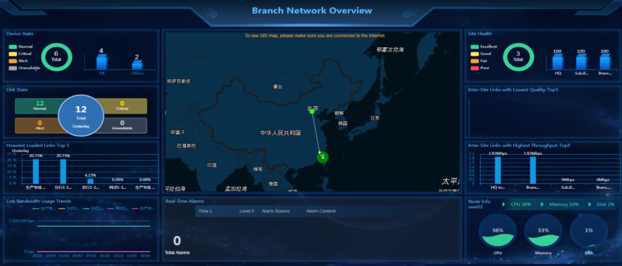
2. Navigate to the Monitor > Topology View > Branch Topology page to view the topology, as shown in Figure 207.
Figure 207 Topology of user sdwan2
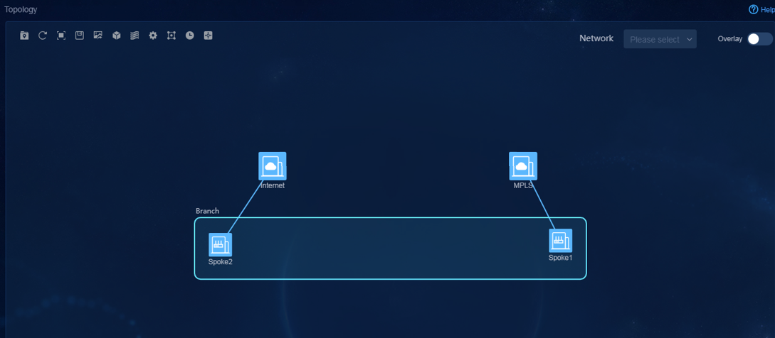
3. Navigate to the Automation > Branch Network > Physical Devices page to view the device information, as shown in Figure 208.
Figure 208 Device list for user sdwan2
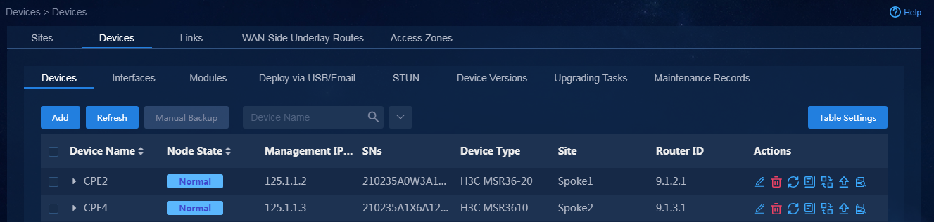
4. Navigate to the Automation > Monitor page to verify that no alarm menu exists and no alarm quantity is displayed in the upper right corner, as shown in Figure 209.
Figure 209 No alarm permission for sdwan2
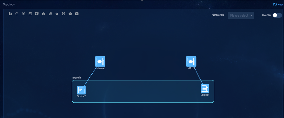
Remote management
The controller can remotely manage a device through the WebSocket channel after the device is successfully registered.
You can implement remote management in the following modes:
· Telnet mode—Connects to the device through Telnet over WebSocket. This mode requires additional device configuration, and supports entering the Tab key and question mark (?) for help information.
Non-telnet mode
1. Log in to Unified Platform as the tenant service administrator (sdwan1).
2. Navigate to the Automation > Branch Network > Physical Network > Devices > Routers > Remote Manage page.
3. Select devices, and turn off the Telnet option to issue commands directly to the devices. For example, you can remotely manage device Spoke1 and query the BGP neighbor state, as shown in Figure 210.
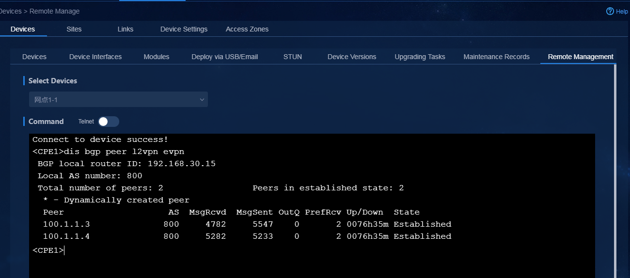
Telnet mode
You can use telnet to remotely manage by using the following methods:
· Username and password authentication—This method requires entering the username and password for login authentication.
· Password authentication—This method requires entering the password for login authentication.
· No authentication—This method does not require login authentication.
Username and password authentication
When managing the device remotely, you must enter the correct username and password for login authentication, and assign controller permissions on the device in the login user settings. You can issue commands in batch to the device (for more information, see "Optimize device settings"). You can also use the non-telnet mode to log in to the device and then issue commands. (For more information, see "Non-telnet mode." You must first enter system view with the system-view command.)
line vty 0 63
authentication-mode scheme //Specify scheme authentication. The default method is username and password authentication.
telnet server enable //Enable telnet server.
local-user telnet //Username used for login.
password simple Pwd@123456 //Authentication password.
service-type telnet //Configure the telnet service type.
authorization-attribute user-role network-admin //Assign user permissions.
1. Log in to Unified Platform as the tenant service administrator (sdwan1).
2. Navigate to the Automation > Branch Network > Physical Network > Devices > Remote Manage page. Select devices, and turn on the Telnet option. As shown in Figure 211, you can remotely manage device Spoke1, and then enter the question mark (?) to obtain command information.
Figure 211 Username and password authentication - telnet mode
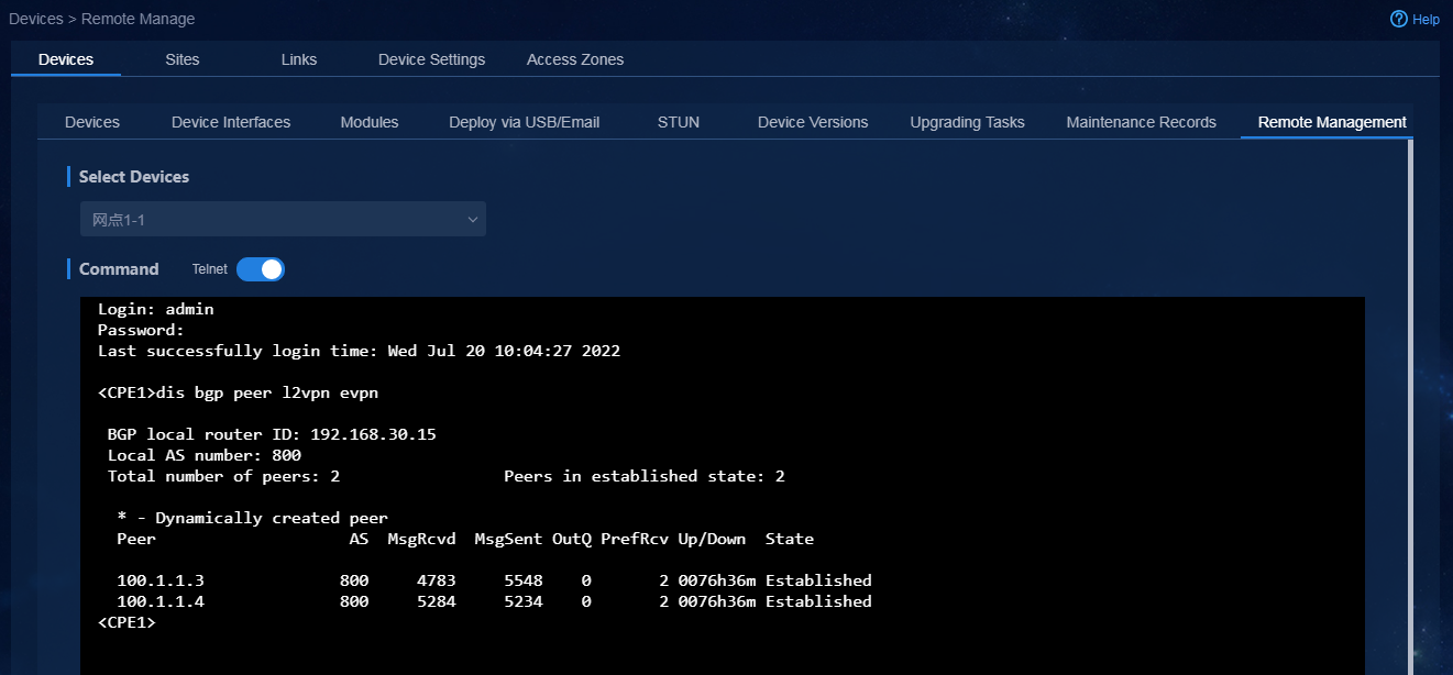
Password authentication
When managing the device remotely, you must enter the correct password for login authentication, and assign controller permissions on the device in the VTY user line. You can issue commands in batch to the device (for more information, see "Optimize device settings"). You can also use the non-telnet mode to log in to the device and then issue commands. (For more information, see "Non-telnet mode." You must first enter system view with the system-view command.)
line vty 0 63
authentication-mode password //Configure password authentication.
set authentication password simple Pwd@123456 //Set the password used for password authentication.
user-role network-admin //Assign user permissions.
telnet server enable //Enable telnet server.
1. Log in to Unified Platform as the tenant service administrator (swan1).
2. Navigate to the Automation > Branch Network > Physical Network > Devices > Remote Manage page.
3. Select devices, and turn on the Telnet option. As shown in Figure 212, you can remotely manage device Spoke1, and then enter the question mark (?) to obtain command information.
Figure 212 Password authentication - telnet mode
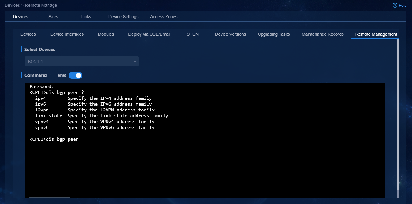
No authentication
Specify to not use authentication, and assign controller permissions on the device in the VTY user line. You can issue commands in batch to the device (for more information, see "Optimize device settings"). You can also use the non-telnet mode to log in to the device and then issue commands. (For more information, see "Non-telnet mode". You must first enter system view with the system-view command.)
line vty 0 63
authentication-mode none //Specify to not use authentication.
user-role network-admin //Assign user permissions.
telnet server enable //Enable telnet server.
1. Log in to Unified Platform as the tenant service administrator (swan1).
2. Navigate to the Automation > Branch Network > Physical Network > Devices > Remote Manage page.
3. Select devices, and turn on the Telnet option. As shown in Figure 213, you can remotely manage device Spoke1, and then enter the question mark (?) to obtain command information.
Figure 213 No authentication - telnet mode
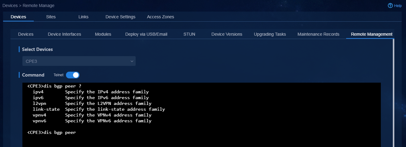
|
|
CAUTION: · The authentication configuration for the VTY user line is the global configuration that must be compliant with the user security policy. As a best practice, use the username and password authentication method. · After logging in to the device through telnet, do not use telnet to collect debugging information. If you do so, the system might become faulty. You cannot input Chinese characters. A maximum of six users can log in to the device simultaneously in this mode. |
O&M diagnostic tools
The controller provides two O&M diagnostic tools: ping and tracert. You can perform ping and tracert operations on the specified device to troubleshoot network problems.
Ping
1. Log in to Unified Platform as the tenant service administrator (sdwan1).
2. Navigate to the Automation > Branch Network > Assurance > O&M Diagnostics > Ping page.
3. Click Diagnose to add a ping task, as shown in Figure 214.

Parameters:
¡ Device Name: Select the device to perform the ping operation.
¡ VPN: Specify the VPN instance for the ping operation. After you specify this parameter, the available interfaces for selection are filtered by the VPN instance.
¡ Output Interface Name: Select an output interface for sending ICMP packets.
¡ Source IP: Specify the source IP address for sending ICMP packets.
¡ Destination Address: Specify the destination IP address or host name. To specify a host name, make sure the host name can be correctly resolved.
¡ Packet Size: Specify the size of ICMP echo request packets.
¡ Packet Count: Specify the number of times to send ICMP echo request packets.
4. Click OK to start the ping operation.
After a period of time when the ping operation is successful, you can view the ping result, as shown in Figure 215.
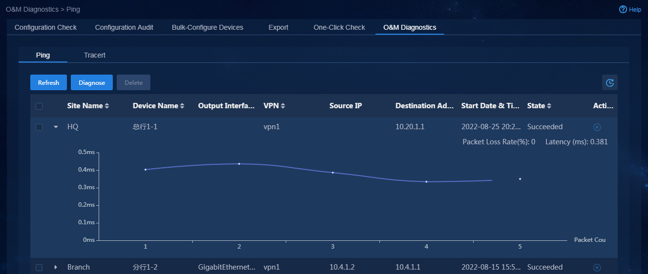
Tracert
1. To correctly display the tracert result, execute the following commands on all devices in the forwarding path.
<spoke1>system-view
[spoke1]ip ttl-expires enable
[spoke1]ip unreachables enable
2. Log in to Unified Platform as the tenant service administrator (sdwan1).
3. Navigate to the Automation > Branch Network > Assurance > O&M Diagnostics > Tracert page.
4. Click Diagnose to add a tracert task, as shown in Figure 216.
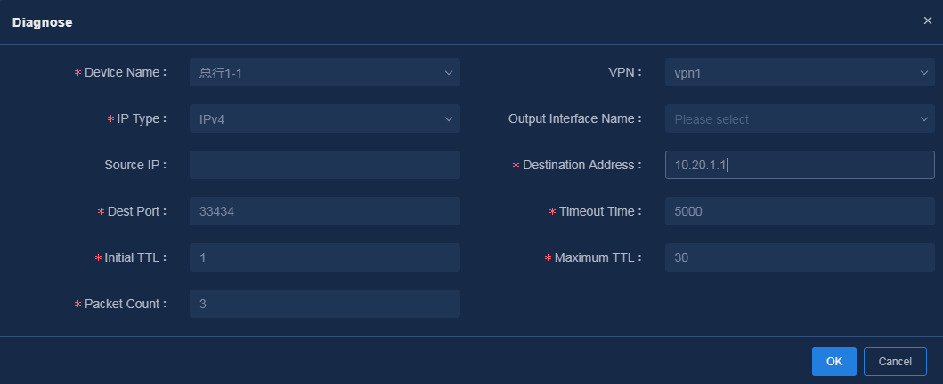
Parameters:
¡ Device Name: Select the device to perform the tracert operation.
¡ VPN: Specify the VPN instance for the tracert operation. After you specify this parameter, the available interfaces for selection are filtered by the VPN instance.
¡ Output Interface Name: Select an output interface for sending tracert packets.
¡ Source IP: Specify the source IP address for sending probe packets.
¡ Destination Address: Specify the destination IP address or host name. To specify a host name, make sure the host name can be correctly resolved.
¡ Dest Port: Typically, this parameter does not need to be edited. If the destination address of the tracert operation is the EID address in a remote LISP site, the destination UDP port number must be equal to or larger than 33434.
¡ Timeout Time: Specify the response timeout timer for probe packets.
¡ Initial TTL: Specify the maximum hop count allowed in the first packet.
¡ Maximum TTL: Specify the maximum hop count allowed in a packet.
¡ Packet Count: Specify the number of times to send probe request packets.
5. Click OK to start the tracert operation.
After a period of time when the tracert operation is successful, you can view the probe result (in a table by default), as shown in Figure 217. To display the path that the probe packets have traversed in a diagram, turn on the Diagram option in the upper right corner, as shown in Figure 218.
Figure 217 Tracert result displayed in a table
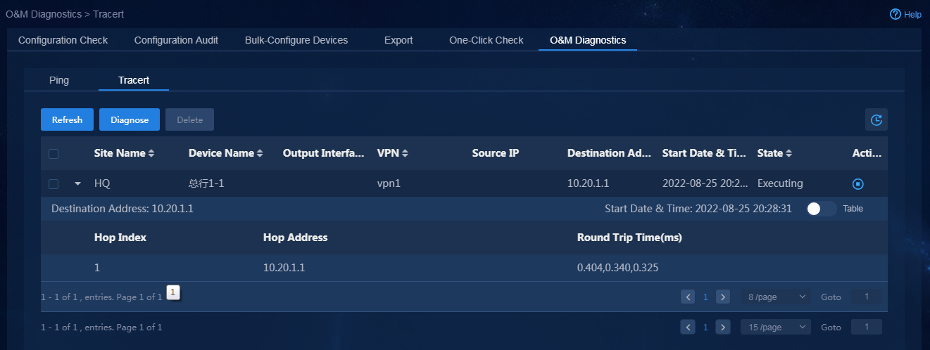
Figure 218 Tracert result displayed in a diagram
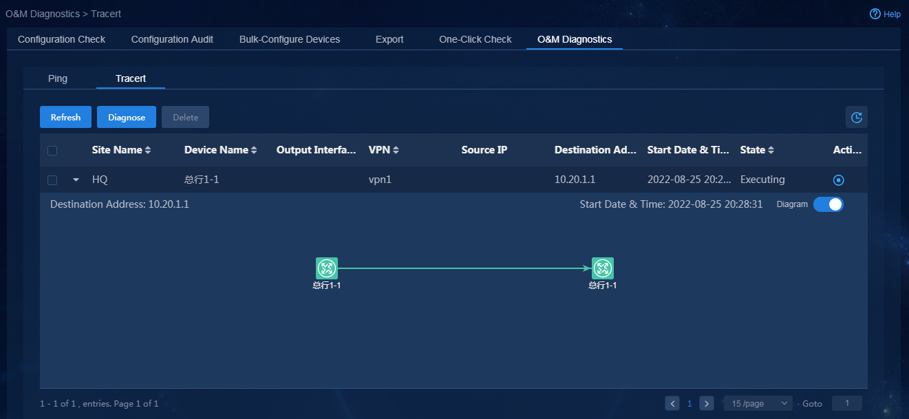
Device software upgrade
The controller can upgrade the software version of routers on a per router basis or in bulk. To download the software version for upgrade, the routers use HTTPS to access port 35000 associated with the unified northbound IP address of the controller.
Figure 219 shows the device software upgrade workflow.
Figure 219 Device software upgrade workflow
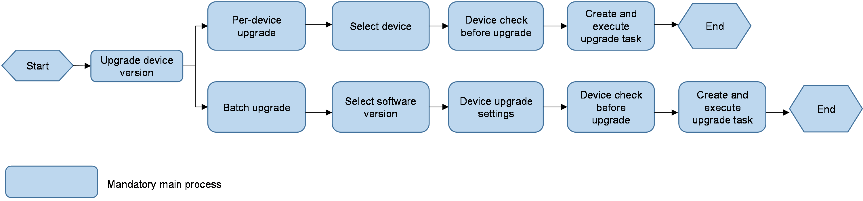
|
|
CAUTION: · With a firewall deployed before the controller, the controller must open TCP port 35000 associated with the unified northbound IP address. · With a NAT device deployed before the controller to map the northbound IP address of the controller to the external network, you must add a mapping between the same public network address and TCP port 35000. |
Upload device software version to be upgraded
1. Log in to Unified Platform as the tenant service administrator (sdwan1).
2. Navigate to the Automation > Branch Network > Physical Network > Devices > Device Versions page.
3. Click Upload to upload a device software version.
The supported file formats include IPE and BIN. The uploaded files will be sorted by device model and version number, as shown in Figure 220.
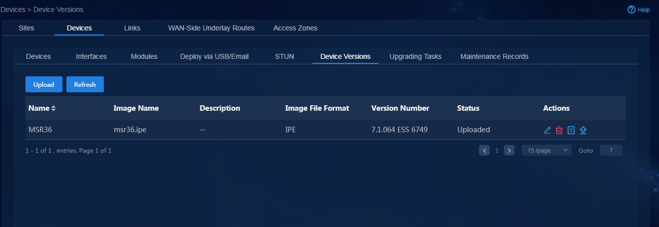
|
|
CAUTION: · The supported file format for uploading can only be IPE or BIN. Make sure each file has a unique name. · The controller supports software upgrade by using only the IPE or BIN files. · For SR66 series devices (corresponding to X3, X5, X5E main control units), you must ensure that the version used for uploading/upgrade is consistent with the device model. The controller cannot accurately filter the versions according to the main control unit model of SR66. Therefore, you must specify the correct version when performing an upgrade. |
Per-device software upgrade
Select a device for upgrading
1. Log in to Unified Platform as the tenant service administrator (sdwan1).
2. Navigate to the Automation > Branch Network > Physical Network > Devices > Devices page.
3. Click the ![]() icon in the Actions
column for the target device to display the supported software image files
supported by the device model, as shown in Figure 221.
icon in the Actions
column for the target device to display the supported software image files
supported by the device model, as shown in Figure 221.
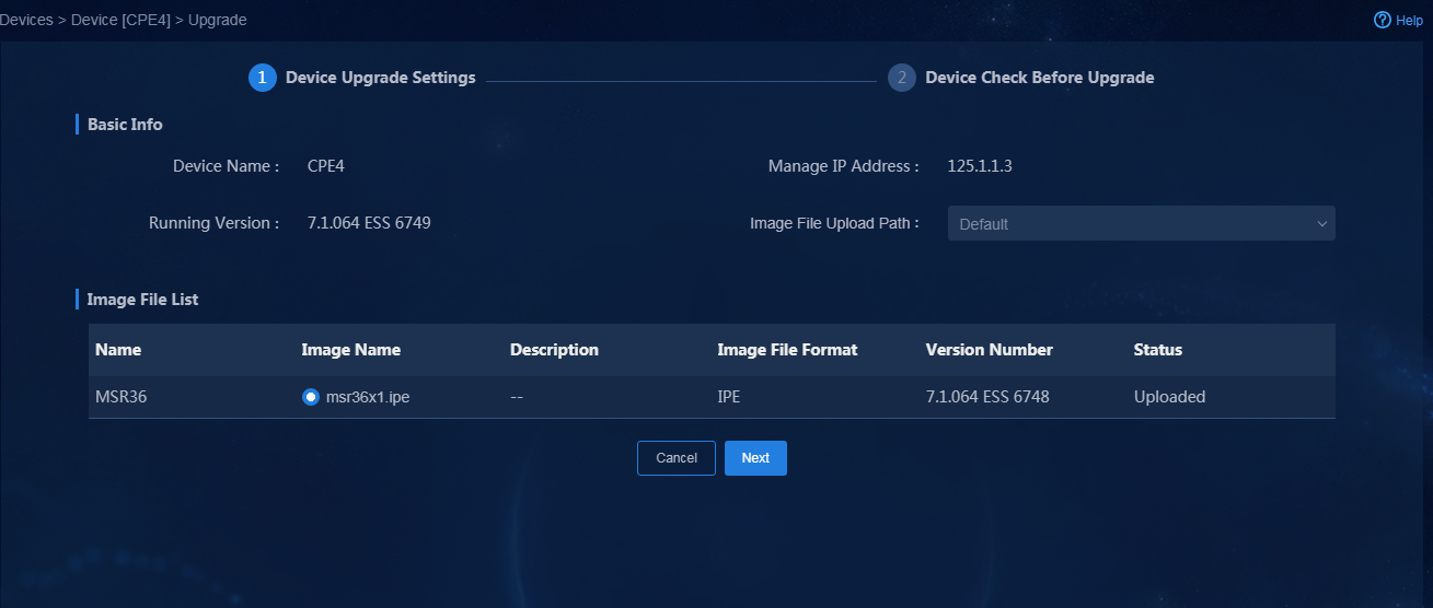
4. Edit the image file upload path as needed. Typically, the default path is used.
5. Select the image file for upgrade, and then click Next to enter the Device Check Before Upgrade page.
Device check before upgrade
Figure 222 shows the Device Check Before Upgrade page.
Figure 222 Device check before upgrade
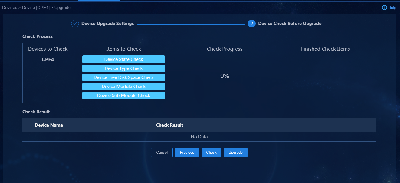
1. Click Check to check the following items on the device:
¡ Device State Check: A device can be upgraded only when it is online.
¡ Device Module Check: Checks whether the device version has been damaged. Because upgrade based on IPE file requires a save and reboot operation, device version damage might result in configuration loss.
¡ Device Type Check: Checks whether the device model matches the image file.
¡ Device Free Disk Space Check: Checks whether the remaining disk space on the device can meet the upgrade requirements. For a successful upgrade, make sure the remaining space is twice the size of the IPE file to save the IPE file and the decompressed BIN file.
Figure 223 shows the device has successfully passed the checks.
Figure 223 Device check result
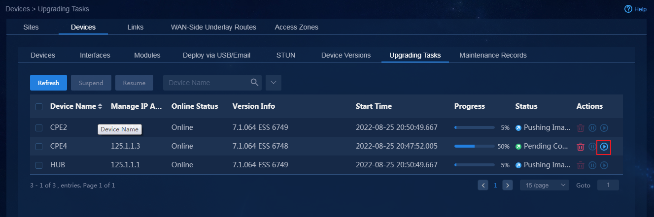
2. After the device check, click Upgrade to create an upgrade task.
|
|
CAUTION: If you do not perform device checks before the upgrade or you forcibly perform an upgrade without a successful upgrade check, the upgrade might fail or configuration loss might occur. Make sure you understand the potential impact before performing such an upgrade. |
Upgrade task
The system automatically starts upgrading after an upgrade task is created.
1. Check the remaining disk space. The upgrade cannot be performed if the remaining disk space is not enough. You cannot skip the check. If the space requirement is not satisfied, you must delete the file on the device, release the space, and then perform the upgrade again.
2. The device automatically downloads the software version through HTTPS.
3. After version download, click the ![]() icon
in the Actions column to continue the upgrade, as shown in Figure 224.
icon
in the Actions column to continue the upgrade, as shown in Figure 224.
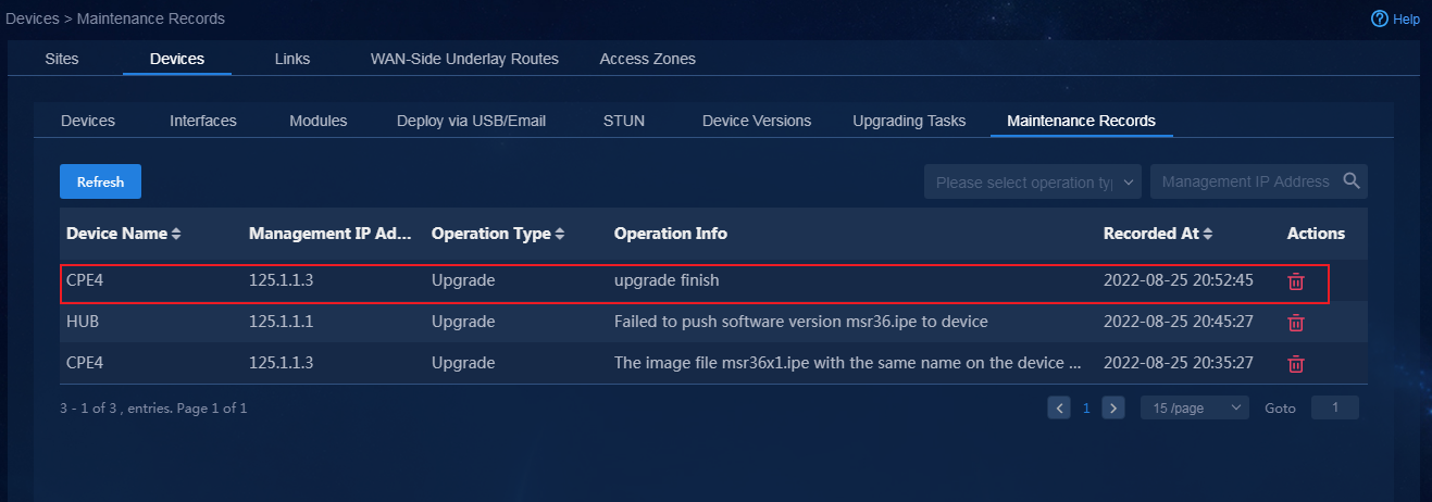
After the associated upgrade command is issued, the device saves the configuration and then reboots to complete the upgrade.
4. Navigate to the Automation > Branch Network > Physical Network > Devices > Maintenance Records page to view the associated upgrade task, as shown in Figure 225.
Figure 225 Maintenance records
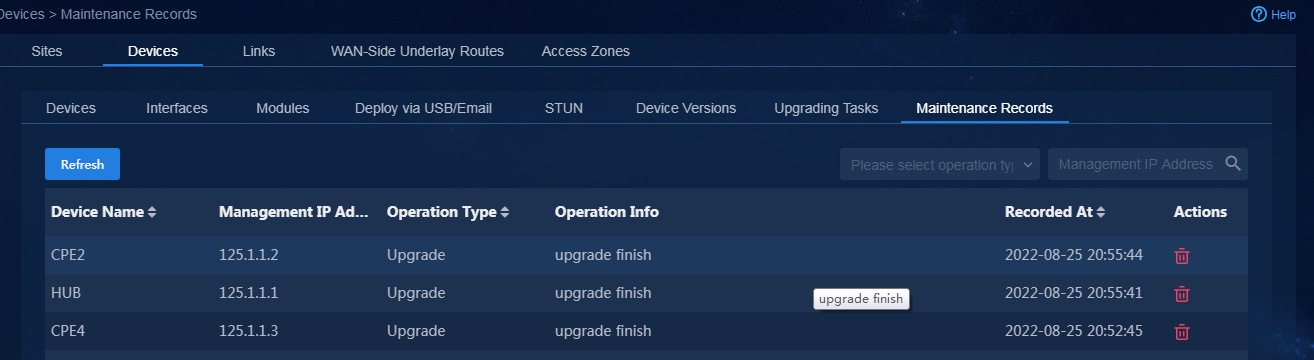
Bulk device software upgrade
Select software version to be upgraded
1. Log in to Unified Platform as the tenant service administrator (sdwan1).
2. Navigate to the Automation > Branch Network > Physical Network > Devices > Device Versions page.
3. Select the target version and click Upgrade to access the Device Upgrade Settings page, as shown in Figure 226.
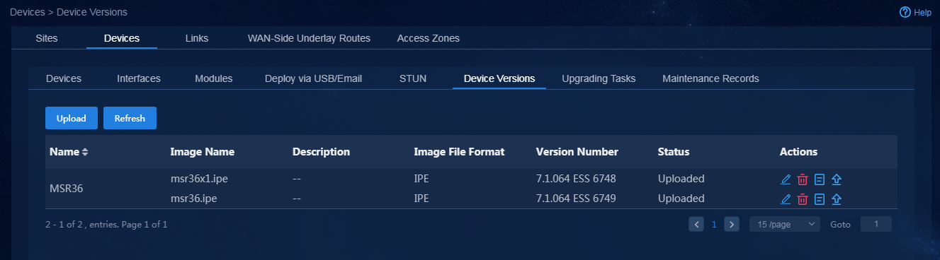
Device upgrade settings
The controller provides all devices applicable to this version.
1. Select the devices to be upgraded in bulk, and then edit the storage location of the version. As shown in Figure 227, select two devices to perform batch upgrade.
Figure 227 Device upgrade settings
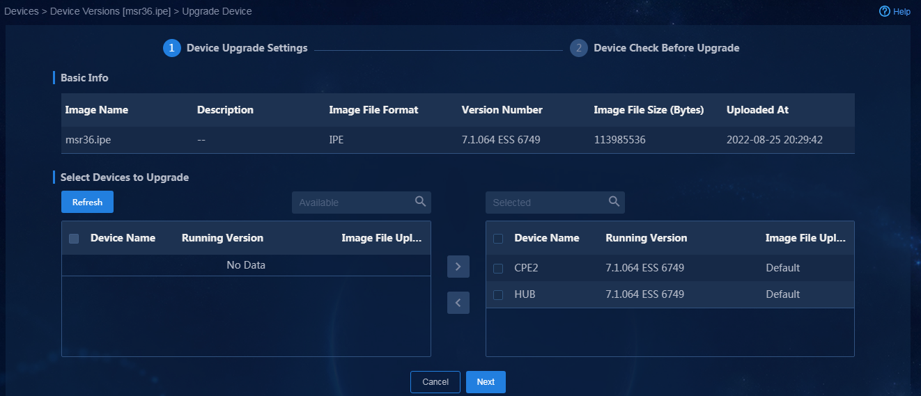
2. Click Next to access the Device Check Before Upgrade page.
Device check before upgrade
Figure 228 shows the Device Check Before Upgrade page.
Figure 228 Device check before upgrade
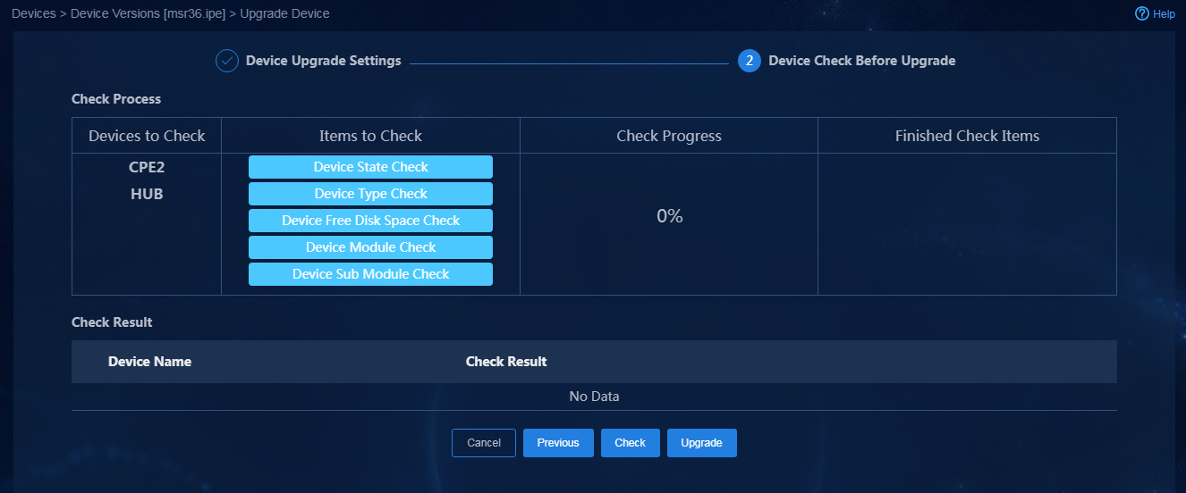
1. Click Check to check the following items on the device:
¡ Device State Check: A device can be upgraded only when it is online.
¡ Device Module Check: Checks whether the device version has been damaged. Because upgrade based on IPE file requires a save and reboot operation, device version damage might result in configuration loss.
¡ Device Type Check: Checks whether the device model matches the image file.
¡ Device Free Disk Space Check: Checks whether the remaining disk space on the device can meet the upgrade requirements. For a successful upgrade, make sure the remaining space is twice the size of the IPE file to save the IPE file and the decompressed BIN file.
The system checks all devices to be upgraded. After the check is complete, the check result is displayed, as shown in Figure 229.
Figure 229 Device check result
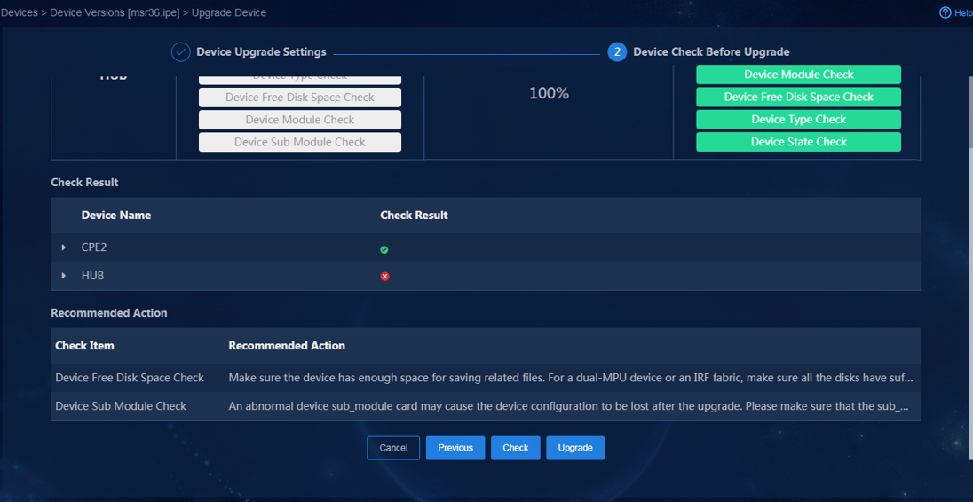
2. After device check, click Upgrade to create an upgrade task.
|
|
CAUTION: · If you do not perform device checks before upgrade or forcibly perform an upgrade without a successful upgrade check, the upgrade might fail or configuration loss might occur. Make sure you understand the potential impact before performing such an upgrade. · The batch upgrade operation might fail (upon expiration of the 10-minute timer) due to bandwidth issues. To perform batch upgrade, select devices with caution according to the network bandwidth. |
Upgrade task
The system automatically starts upgrading after an upgrade task is created.
1. Check the remaining disk space. The upgrade cannot be performed if the remaining disk space is not enough. You cannot skip the check. If the space requirement is not satisfied, you must delete the file on the device, release the space, and then perform the upgrade again.
2. The devices automatically download the software version and all devices download the software version simultaneously.
3. After version download, you can select other devices, and then click Resume to perform upgrade for the selected devices, as shown in Figure 230.
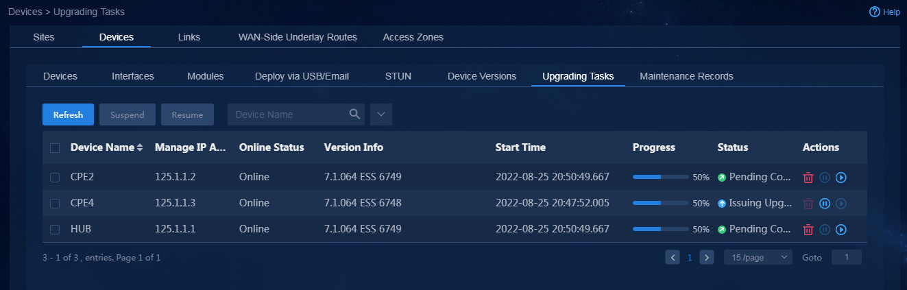
4. After the associated upgrade command is issued, the device saves the configuration and then automatically reboots to complete the upgrade.
5. Navigate to the Automation > Branch Network > Physical Network > Devices > Maintenance Records page to view the associated upgrade task, as shown in Figure 231.
Figure 231 Maintenance records

Backup restoration and replacement
You can perform manual backup or scheduled backup and restore configurations from a backup. If a device requires replacement, you can use the backup and restoration features to fast configure the new device. Routers use HTTPS to access TCP port 35000 of the controller at the unified northbound address to upload or download backup files.
For device configuration backup restoration and replacement workflow, see Figure 232.
Figure 232 Manual backup restoration and replacement workflow
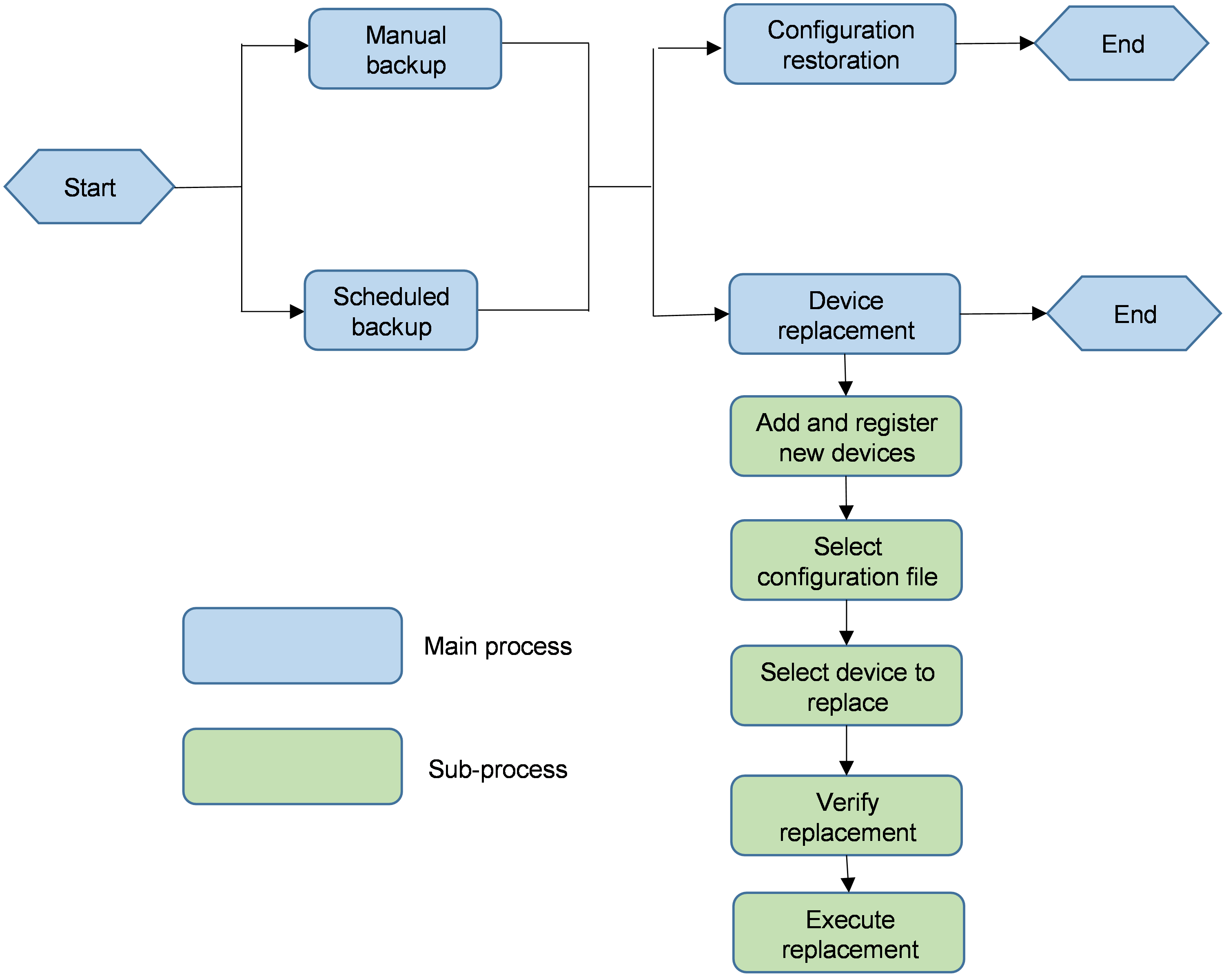
|
|
CAUTION: · With a firewall deployed before the controller, the controller must open TCP port 35000 associated with the unified northbound IP address. · With a NAT device deployed before the controller to map the northbound IP address of the controller to the external network, you must add a mapping between the same public network address and TCP port 35000. |
Back up device configuration manually
1. Log in to Unified Platform by using the tenant administrator account sdwan1.
2. Navigate to the Automation > Branch Network > Physical Network > Devices > Devices page.
3. Click the ![]() icon in the Actions
column for the target device, as shown in Figure 233.
icon in the Actions
column for the target device, as shown in Figure 233.
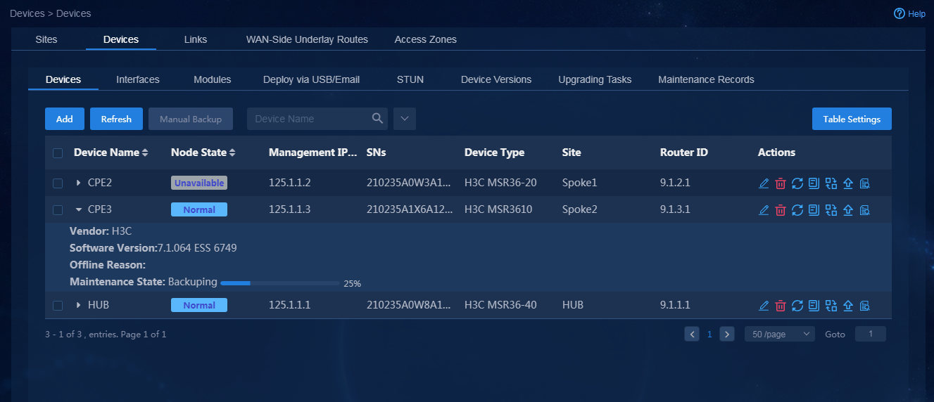
4. To view backup files, click the ![]() icon
in the Actions column for a device, as shown in Figure 234.
icon
in the Actions column for a device, as shown in Figure 234.
Figure 234 Configuration files
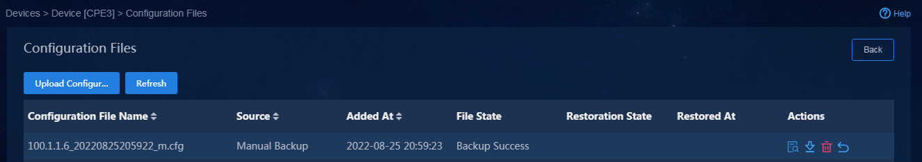
5. Select a configuration file. To download a
configuration file, click the ![]() icon in the Actions
column. To view the preview of a configuration file, click the
icon in the Actions
column. To view the preview of a configuration file, click the ![]() icon,
as shown in Figure 235. You can also click Upload Configuration File to upload a
configuration file.
icon,
as shown in Figure 235. You can also click Upload Configuration File to upload a
configuration file.
Figure 235 Viewing configuration file preview
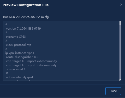
6. To view the configuration backup records, navigate to the Automation > Branch Network > Physical Network > Devices > Maintenance Records page, as shown in Figure 236.
Figure 236 Maintenance records
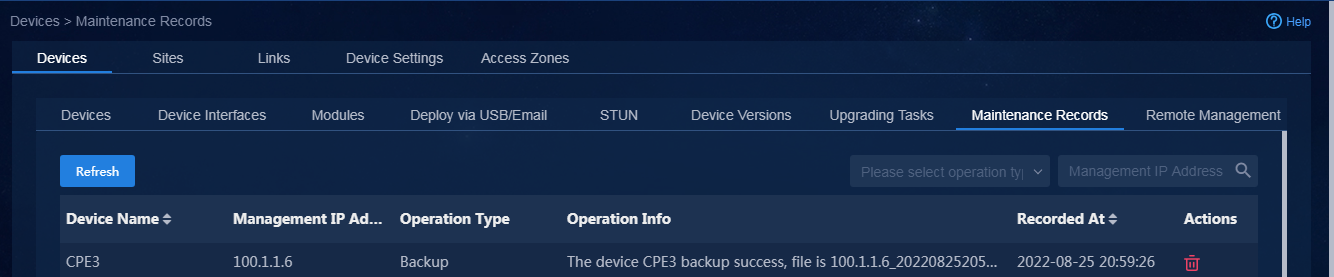
|
|
CAUTION: The system can save a maximum of 30 backup files for a device. If the upper limit is reached, creating a new backup file deletes the oldest one. To save the previous backup files, download them manually. |
Configure scheduled backup
1. Log in to Unified Platform as the tenant service administrator (sdwan1).
2. Navigate to the Automation > Branch Network > Parameter Settings > O & M Settings > Device Scheduled Backup Settings page.
3. Enable Scheduled Backup, as shown in Figure 237.
Figure 237 Configuring scheduled backup
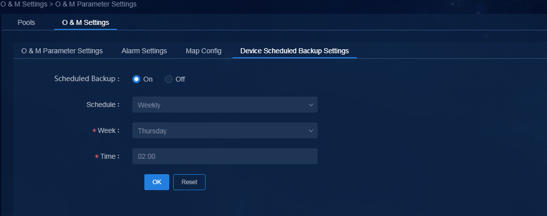
4. After the configuration, the controller
backs up device configuration files automatically at the scheduled time. To
view the backup files, click the ![]() icon in the Actions
column, as shown in Figure 238.
icon in the Actions
column, as shown in Figure 238.
Figure 238 Scheduled backup configuration file
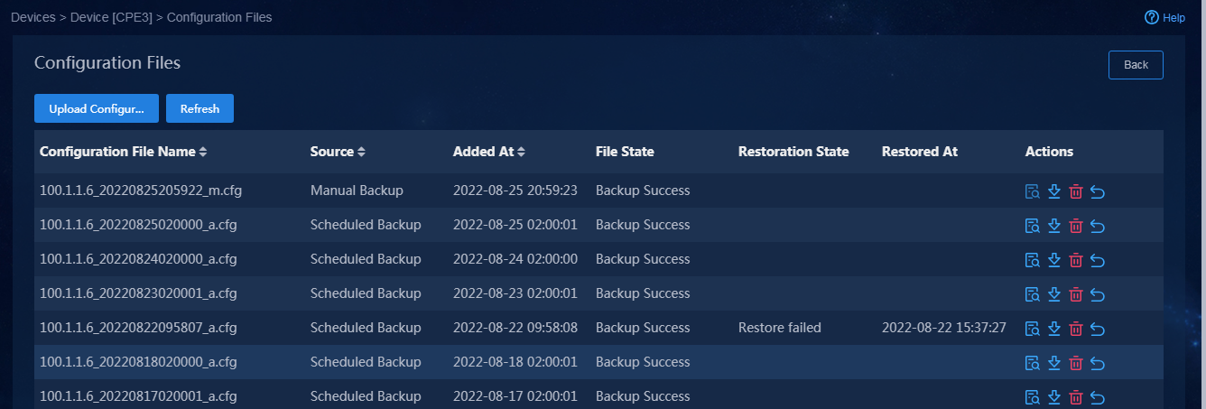
5. Select a configuration file. To download a
configuration file, click the ![]() icon. To query
the configuration file, click the
icon. To query
the configuration file, click the ![]() icon, as shown in
Figure 239. You can also click Upload Configuration File to upload a
configuration file.
icon, as shown in
Figure 239. You can also click Upload Configuration File to upload a
configuration file.
Figure 239 Viewing configuration file preview
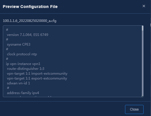
6. To view the configuration backup records, navigate to the Automation > Branch Network > Physical Network > Devices > Maintenance Records page, as shown in Figure 240.
Figure 240 Maintenance records
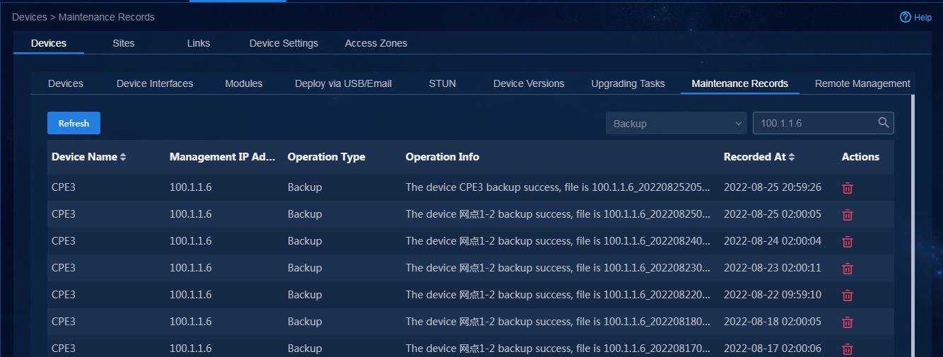
|
|
CAUTION: The system can save a maximum of 30 backup files for a device. If the upper limit is reached, creating a new backup file deletes the oldest one. To save the previous backup files, download them manually. |
Restore configuration
You can restore device configuration from a backup file.
1. Log in to Unified Platform as the tenant service administrator (sdwan1).
2. Navigate to the Automation > Branch Network > Physical Network > Devices > Devices page.
3. Click the ![]() icon to view
backup configuration files for the device, as shown in Figure 241.
icon to view
backup configuration files for the device, as shown in Figure 241.
Figure 241 Configuration files
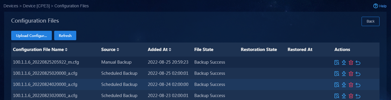
4. Click the ![]() icon for the
target configuration file to restore the configuration. In the dialog box that
opens, click OK, as shown in Figure 242.
icon for the
target configuration file to restore the configuration. In the dialog box that
opens, click OK, as shown in Figure 242.
Figure 242 Confirming configuration restoration
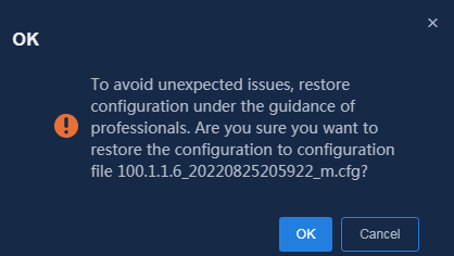
After restoration, the system displays the operation result and configuration restoration time, as shown in Figure 243.
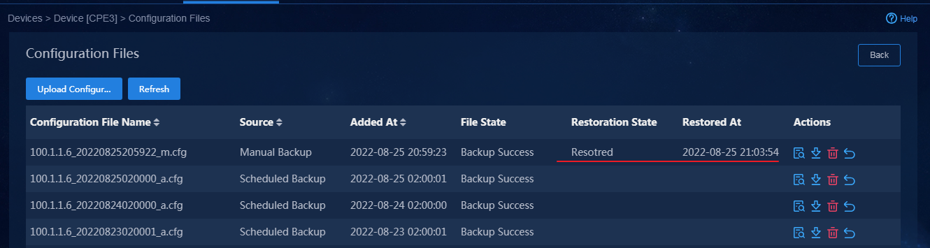
|
|
CAUTION: · To restore configurations from a saved configuration file, the operation might fail if you have manually edited the file. · Configuration restoration uses configuration rollback commands, and restoration failure might occur out of various issues. Use this feature with caution. |
Replace a device
After backing up device configurations, if a device fails, you can back up the device configurations and replace the faulty one with a device of the same model.
At present, you can replace a standalone device or a member of an IRF fabric.
Add and register a new device
1. Log in to Unified Platform as the tenant service administrator (sdwan1).
2. Navigate to the Automation > Branch Network > Physical Network > Devices > Devices page.
3. Click Add to open the Add Device page, as shown in Figure 244. The device name and router ID are configured temporarily.
After replacement, the device name and router ID will be replaced by the settings of the faulty device. For the device to register successfully, make sure the SN is correct.
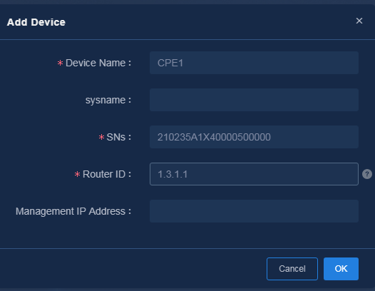
4. Configure device registration.
¡ For a standalone device, remove cables from the faulty device and connect them to the new device in the same way. The new device will automatically use the configuration of the faulty one to register because they are connected the same way. Therefore, you do not must bind its site or import WAN details after adding the device. If the faulty device was configured from a URL or by using a USB disk, you can configure the new device in the same way. For more information, see "Deploy devices via USB/email." If you successfully replace the faulty device with a new device, the faulty device will be offline, as shown in Figure 245.
Figure 245 Viewing device registration status
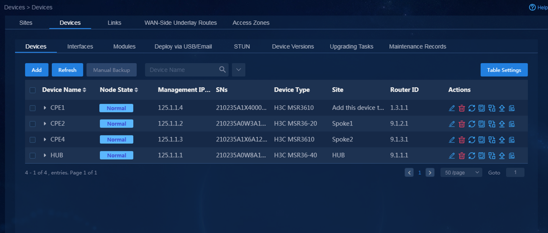
¡ For a member of an IRF fabric, remove cables from the faulty device and connect them to the new device in the same way, and then load the corresponding configurations for the new device to perform registration and come online. As a best practice, manually configure routing and registration settings for the new device. For more information, see "Manually deploy devices."
Execute device replacement
1. Click the ![]() icon for the
faulty device.
icon for the
faulty device.
2. Select the configuration file to use, specify the faulty device SN if the faulty device is a member of an IRF fabric, as shown in Figure 246, and then click Next.
Figure 246 Configuring faulty device settings
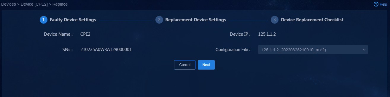
3. Select the new device name, as shown in Figure 247, and then click Next.
Figure 247 Configuring new device settings
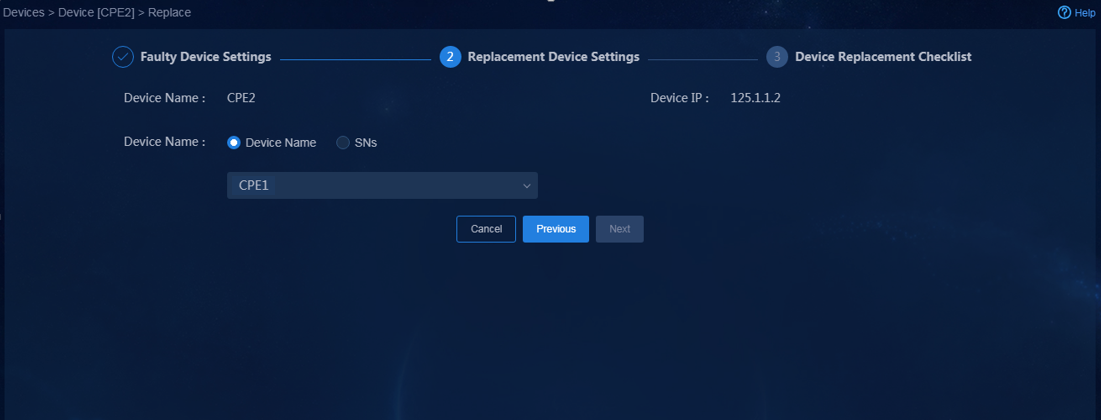
4. Check the following items:
¡ Configuration file: Verify that the file exists on the server.
¡ Faulty device state: Verify that the faulty device or faulty IRF member is offline.
¡ New device management state: Verify that the new device is managed by the controller.
¡ Device type: Verify that the new device and the faulty device are of the same model.
¡ Software version: Verify that the new device and the faulty device use the same software version.
¡ New device remaining disk space: Verify that the available disk space on the new device can meet the requirements.
¡ As shown in Figure 248, after performing pre-replacement check, click Replace.
Figure 248 Performing pre-replacement check
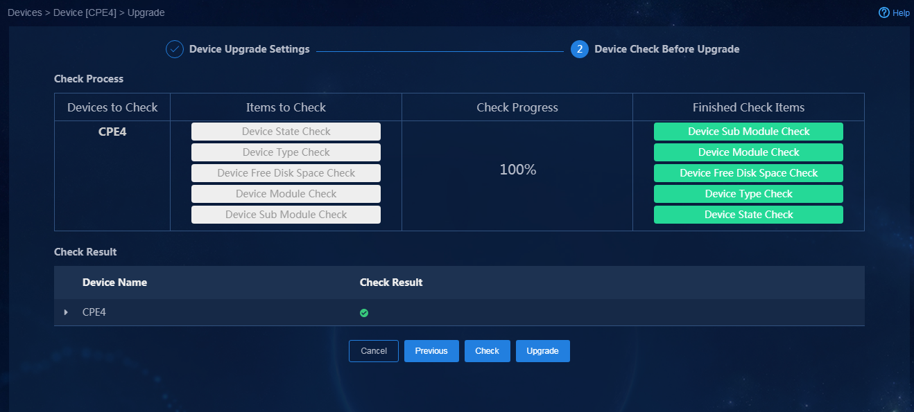
The replacement task information is displayed. The controller pushes configurations to the new device, sets the configuration file as the startup file, and then restarts the device.
¡ For standalone devices, the replacement finishes after restart and the device SN is updated to the SN of the new device.
¡ For IRF fabric members, manually switch connections of the faulty member to the new member, including fabric connections, to rebuild the fabric. After fabric rebuilding, the device SN will be updated to the SN of the new device and the new device entry is removed, as shown in Figure 249.
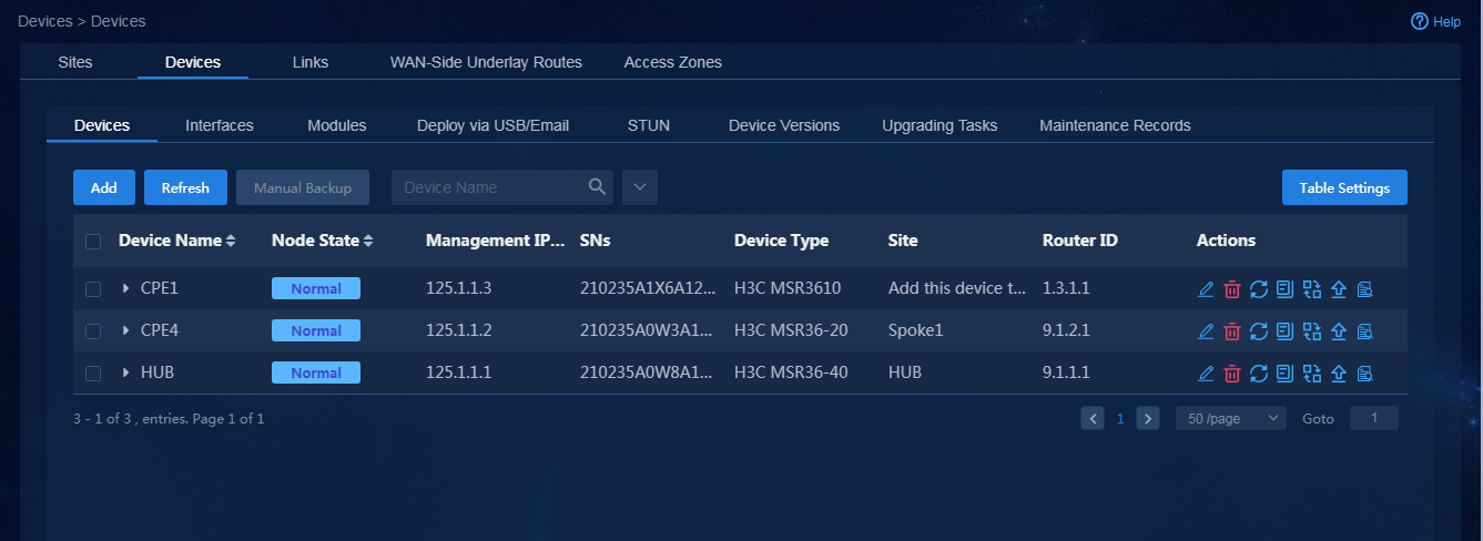
5. To view the replacement record, navigate to the Automation > Branch Network > Physical Network > Devices > Maintenance Records page.
|
|
CAUTION: For a successful replacement, make sure the new device uses the factory configuration when you replace a faulty device with a new one. |
Configuration audit
The controller enables the configuration audit feature. The feature can compare device running configurations and configurations saved in the controller database and display the differences. You can view, manage (synchronize or ignore), or export the differences, and modify inconsistent configurations as needed.
Configuration audit
1. Log in to Unified Platform as the tenant service administrator (sdwan1).
2. Navigate to the Automation > Branch Network > Assurance > Configuration Audit page, as shown in Figure 250.
Figure 250 Configuration audit
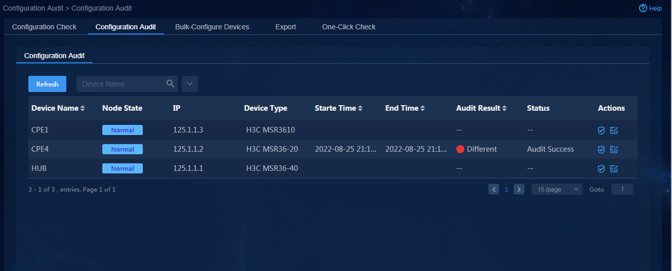
3. To perform a configuration audit, click the Start
Audit icon ![]() in the Actions column.
in the Actions column.
4. To view the result of the most recent audit
for a device, click the Audit Result icon ![]() in
the Actions column. You can filter the audit result by data modules,
data type, and data status, as shown in Figure 251.
in
the Actions column. You can filter the audit result by data modules,
data type, and data status, as shown in Figure 251.

The display and operation of the audit results are based on the configuration saved by the controller. The operation instructions are as follows:
¡ For configuration existing only on the controller, you can synchronize the configuration to the device. Select the configuration and click Synchronize to deploy the configuration to the device.
¡ For configuration existing only on a device, you can synchronize the configuration to the controller or ignore it. Select the configuration and click Synchronize to delete the configuration on the device. Click Ignore and the configuration on the device will be changed.
¡ For configuration inconsistency, you can synchronize configurations on the controller to the device. Select the configuration and click Synchronize to edit the configuration on the device to be consistent with that on the controller.
¡ For differences generated due to module errors, you can only view configurations affected by module soft deletion.
|
|
CAUTION: Synchronizing configurations to a device might affect service operation. Please contact Technical Support first. |
Configuration check
The controller enables configuration check. This feature enables you to obtain the specified configurations from devices or compare device configurations.
Obtain device configurations
1. Log in to Unified Platform as the tenant service administrator (sdwan1).
2. Navigate to the Automation > Branch Network > Assurance > Configuration Check > Obtain Configuration page.
3. Select devices, and then click Obtain Configuration, as shown in Figure 252.
The tab displays the most recent time at which device configuration was obtained and the operation result. You can view and dispose of the obtained configuration file on the Compare Configuration page. The system can save up to 5 device configuration files. If the limit is reached, you must first delete files on the Compare Configuration tab before obtaining more device configurations.
Figure 252 Obtaining device configuration
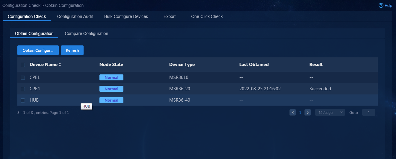
Compare configurations
Perform this task to download, delete, and edit remarks for configuration files and compare device configurations.
1. Log in to Unified Platform as the tenant service administrator (sdwan1). Navigate to the Automation > Branch Network > Assurance > Configuration Check > Compare Configuration page. On this page, select a device from the drop-down option box, and then you can view all the configuration files obtained by the device.
2. Click the ![]() icon in the Actions
column, and then you can edit, delete, or download the configuration files, as
shown in Figure 253. To compare device configurations, select two files, and then click
Compare. Then, the comparison result of the two configuration files pops
up, as shown in Figure 254.
icon in the Actions
column, and then you can edit, delete, or download the configuration files, as
shown in Figure 253. To compare device configurations, select two files, and then click
Compare. Then, the comparison result of the two configuration files pops
up, as shown in Figure 254.
Figure 253 Comparing configuration
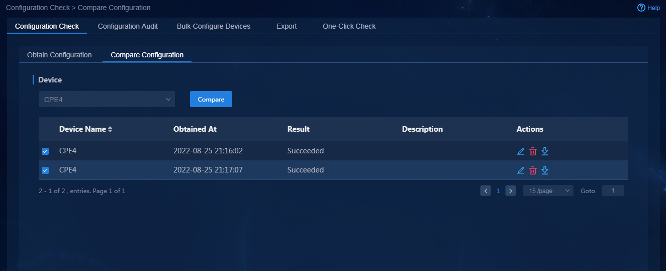
Figure 254 Configuration comparison result

O&M monitoring
For more information, see H3C AD-WAN Branch Solution 6.2 O&M and Deployment Guide.
