
- Released At: 13-09-2023
- Page Views:
- Downloads:
- Table of Contents
- Related Documents
-
|
|
|
H3C AD-Campus 6.2 Solution |
|
Maintenance Guide |
|
|
|
|
Document version: 5W100-20230221
Copyright © 2023 New H3C Technologies Co., Ltd. All rights reserved.
No part of this manual may be reproduced or transmitted in any form or by any means without prior written consent of New H3C Technologies Co., Ltd.
Except for the trademarks of New H3C Technologies Co., Ltd., any trademarks that may be mentioned in this document are the property of their respective owners.
This document provides generic technical information, some of which might not be applicable to your products.
The information in this document is subject to change without notice.
H3C Unified Platform deployment
Application packages required for deploying the Unified Platform
Collect Installer diagnosis information
Perform a full upgrade for Installer with a version earlier than V900R001B06D011
Fix the issue of beginning installation without network configuration
Fix the invalid host name issue in server cluster deployment
Edit the system time zone after the installation of the H3Linux OS on a node
Collect the Unified Platform log information
Cluster anomalies and resumption
Add the vpn-default VPN instance before a software upgrade or data backup for spine or leaf devices
Avoid transmitting large files to Unified Platform during a device software upgrade
Resolve disk parity check failure during a component package upload
Avoid restoring data of Unified Platform across software versions
Restrictions for Unified Platform deployment on a VM
How to select network adapters when creating networks
How to start up network adapters when creating networks
How to configure the VLAN field when creating networks
How to permit all VLANs in VMware ESXi version 6.7
Restart of the network adapter in a container leads to the loss of default routes in that container
Avoid connecting multiple controllers to the same license server
Resolve the network fault caused by dedicated NICs of SeerEngine-Campus and Unified Platform
Resolve trap report failure after physical network element incorporation by SeerEngine-Campus
Devices configuration must be restored to factory defaults for automatic onboarding
Restoration of the device configuration to factory defaults
RR MAC configuration in the automatic deployment
Avoid changing the DHCP server for automated device deployment
View serial numbers of devices
Stacked access devices does not support BFD MAD
Fix the AP flapping issue triggered by the STP attack packets sent by clients
Fix the large broadcast or multicast traffic issue on AP-facing interfaces of access or leaf devices
Auto deployment of devices must be conducted by level in order
Device version upgrade and supported file formats for upgrading
Remaining capacity required for device version upgrade
A template can be used to upgrade devices only model by model during automated deployment
Enable/disable whitelist in the automation template
Whitelist verification failure during device auto onboarding
After the auto onboarding, the spine device cannot obtain the VSI4094 interface IP address
After the auto stacking, the single leaf model cannot acquire the VSI4094 interface IP address
Collection of logs related to auto deployment
Process exits during the automation
Interface configuration not deployed
Stacking failure during auto deployment
Locate the defected phase in an auto deployment failure
When the device is automatically deployed, its status will remain as managing
MAD restrictions for access device stacking
Topology changes might result in deletion of interface configuration
Device resources incorporation
After the device is incorporated, there are configurations not deployed successfully
Devices auto-deployed after a stack split cannot be incorporated
Multiple controllers cannot manage the same device
A compatible Huawei device is inactive after incorporation
The general policy groups created manually cannot be configured with the default system group policy
When the AAA policy template is modified, the MAC Portal user authentication cannot succeed
Authentication method of an 802.1X device policy template (LDAP scenario)
Private networks and security groups are not deployed to devices
Switching DHCP servers for the subnets of security groups
Secondary subnets usage restrictions
Access to IT resources when inter-group policies use the global Deny as default action
Keeping broadband IoT endpoints online
Configure a static route on an external connection device
Configure IRF bridge MAC persistence
VXLAN mode modification on the S5560/S6520X series
The status of the incorporated devices on the controller is inactive
Dedicated egress router for interconnection of multiple fabrics
Permit port numbers and service subnets
An access user is created, but the user is shown as not existed during authentication
Authentication with iNode client fails
When EAD is not deployed on the EIA, the iNode client cannot configure the EAD server IP address
Possible causes for user login authentication failures
Authentication with a non-H3C client fails
Upload IP addresses after users with static IP logged in
Authentication page cannot open on MAC Portal authentication endpoints
DHCP address cannot be obtained after user login
Primary/secondary leaf device switchover causes users offline (online check)
User disconnection during a master node upgrade for Matrix
The DHCP server cannot be changed when users are online
Downlink interface flapping on a leaf device interrupts services
Switching between wireless AP modes
Apply a routing policy to service VPNs when there are many wireless APs
It takes longer time than expected for EIA to synchronize wireless user IP address changes
EIA does not display IPv6 addresses of wireless users
Automatic link aggregation is not supported by WTs
View the vDHCP address pool and address allocation
View the primary and secondary nodes of vDHCP
vDHCP primary and secondary IP address pools not synchronized
vDHCP supports only the HA mode in a cluster environment
The clock difference between Microsoft DHCP HA servers should not exceed 1 minute
The vlan4094 IP address pool is required on Microsoft DHCP server
The Microsoft DHCP server supports IPv4/IPv6 dual stack
Only the primary DHCP server can create account-name bindings in a Microsoft DHCP HA environment
Ports required to be opened if firewalls exist
It is forbidden to deploy GRPC configurations through the controller
SeerAnalyzer restrictions of the S5560X and S6520X series devices
Disable devices from sending ARP and MLD packets received from VXLAN tunnels to CPUs
Enable ARP packet rate limiting for specific source MAC addresses
Disable gratuitous ARP learning
Shut down the VLAN interface of VLAN 1 on access devices
H3C Unified Platform
H3C Unified Platform deployment
H3C Unified Platform is related to H3Linux and the Installer. For more information, see the Unified Platform release notes. Please strictly follow the H3C Unified Platform Deployment Guide for all deployment-related operations.
|
|
NOTE: If the Unified Platform is deployed on the SeerBlade, the SeerBlade module disks do not support HA. |
Application packages required for deploying the Unified Platform
|
Functions |
Description |
|
|
common_H3Linux-<version>.iso |
Package of the H3Linux OS |
Required |
|
common_PLAT_GlusterFS_2.0_<version>.zip |
Local shared storage |
Required |
|
general_PLAT_portal_2.0_<version>.zip |
Portal, unified authentication, user management, service gateway, support center |
Required |
|
general_PLAT_kernel_2.0_<version>.zip |
Permissions, resource identities, Licenses, configuration center, resource groups, log service |
Required |
|
general_PLAT_kernel-base_2.0_<version>.zip |
Alarms, access parameter templates, monitor templates, reports, mail and SMS forwarding service |
Required |
|
general_PLAT_network_2.0_<version>.zip |
Basic network management (network resources, network performance, network topology, iCC) |
Required |
|
general_PLAT_kernel_region_2.0_<version>.zip |
Hierarchical management |
Optional |
|
general_PLAT_Dashboard_2.0_<version>.zip |
Large screen dashboard |
Required |
|
general_PLAT_widget_2.0_<version>.zip |
Large screen widgets |
Required |
|
general_PLAT_websocket_2.0_<version>.zip |
Southbound WebSocket |
Required |
|
ITOA-Syslog-<version>.zip |
Syslog-related functions |
Required for SeerAnalyzer |
Configure a dedicated etcd disk (required for physical machine deployment and virtual machine deployment)
Before ISO installation, prepare a dedicated physical disk to mount the etcd directory. Do not use a partition. Disk requirements are as follows:
· Type—SSD or 7.2K RPM SATA/SAS HDD
· Etcd disk capacity—50 GB and above after RAID configuration
· Mounting path—/var/lib/etcd
The dedicated etcd disk is required for physical machine deployment and virtual machine deployment.
The dedicated etcd disk is not required from PLAT 2.0 (E0706). As a best practice, install the system and components on a physical disk other than the etcd disk. If this requirement cannot be satisfied, use an SSD, a 7.2K RPM HDD with a 1GB RAID controller, or an HDD with higher performance. An SSD is recommended.
License registration
1. Navigate to System > License Information.
2. After the system is installed and deployed, there is a trial license by default for temporary use.
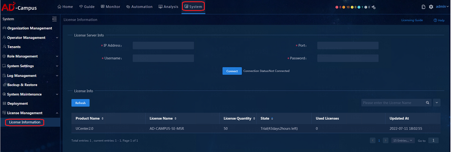
3. The license server configuration is shown below. After the configuration is complete, click Connect to connect with the License Server.
¡ IP address: Enter the license server IP address. Make sure the cluster's northbound IP address and the license server can communicate with each other.
¡ Port: 5555;
¡ Username: admin (the client name in the license server configuration);
¡ Password: admin@123 (the client password in the license server configuration)
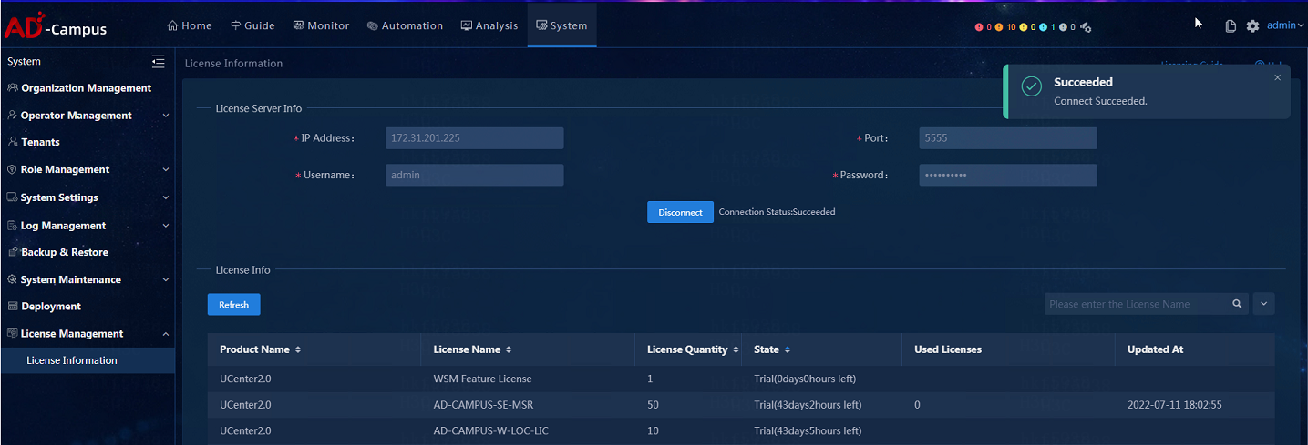
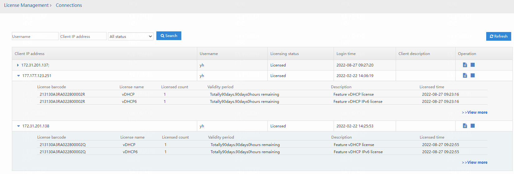
When the license registration is finished, the registered licenses will be listed, as shown below:
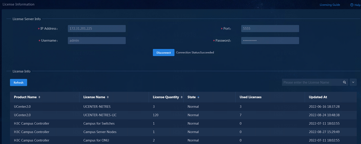
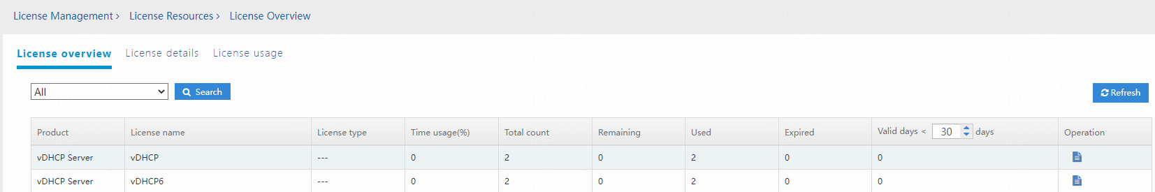
vDHCP licenses are not displayed in the license list. To view the vDHCP licenses, access the license server. vDHCP R1114 does not require vDHCP licenses.
Installer login
You can access Installer by using a Chrome browser. The website address is https://ip address:8443/matrix/ui/, where the IP address is the host node IP address or the cluster northbound IP address (the northbound IP address set during the cluster deployment). The login username and password are admin and Pwd@12345.
Collect Installer diagnosis information
Log in to Installer by using the following information in a Chrome browser:
· Web interface login address: https://ip:8443/matrix/ui/
· Username and password: admin and Pwd@12345
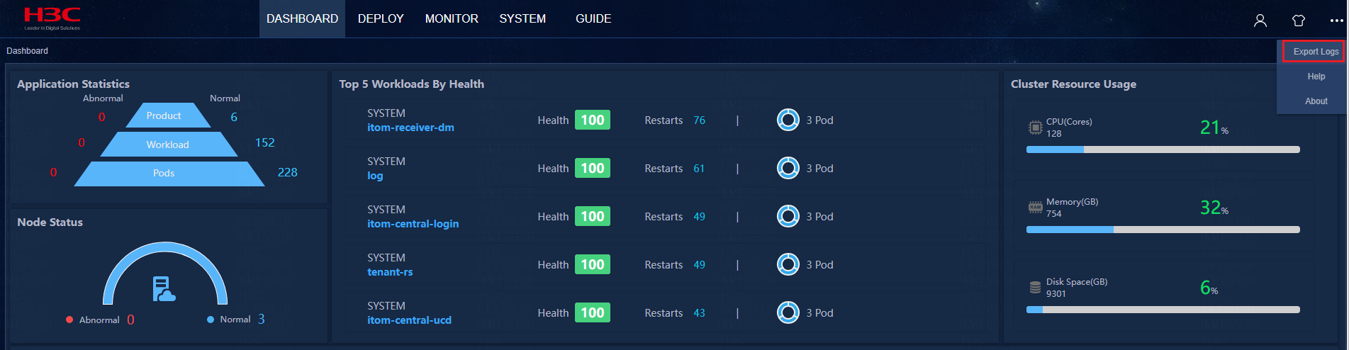
Click ![]() on top right of the Installer page, and click Export Logs in
the pop-up menu to export logs to the local device.
on top right of the Installer page, and click Export Logs in
the pop-up menu to export logs to the local device.
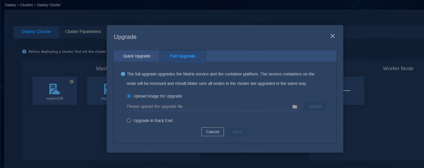
Perform a full upgrade for Installer with a version earlier than V900R001B06D011
Installer before V900R001B06D011 (E0611 for Unified Platform) supports only the full upgrade mode. To upgrade a software version earlier than E0611 to E0611, you must perform a full upgrade as described in H3C Unified Platform Deployment Guide.
Fix the issue of beginning installation without network configuration
Issue
During the installation of ISO, after changing the host name, you forgot to click Configure ... to complete the network configuration, but directly clicked Done and then clicked Begin Installation on the installation information summary page.
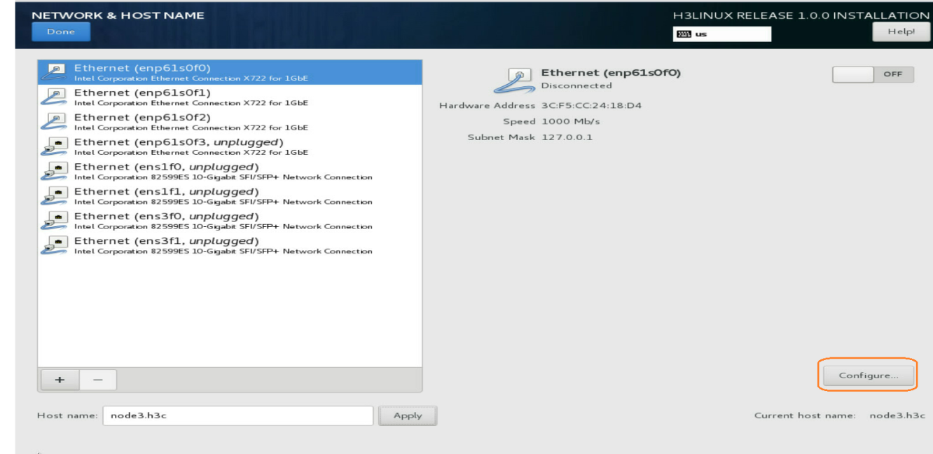
Solution
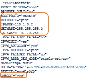
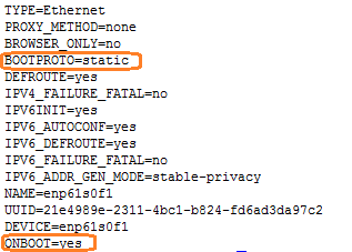
1. Execute the following commands to edit the BOOTPROTO and ONBoot parameters in the network adapter configuration file:
# ifconfig //View the network adapter.
# cd /etc/sysconfig/network-scripts //Enter the /etc/sysconfig/network-scripts path to view the network adapter configuration file.
# vi /etc/sysconfig/network-scripts/ ifcfg-enp61s0f0 //Edit the network adapter configuration as appropriate.
2. Restart the network adapter.
# systemctl restart network
Fix the invalid host name issue in server cluster deployment
Issue
On the Guide > Create Cluster page of Installer, a message of "The host name of the node is invalid" is displayed.
Solution
The host name can contain a maximum of 63 characters. It supports only lowercase letters, digits, hyphens (-), and dots (.), and cannot start or end with a hyphen (-) or a dot (.).
1. Log in to the server where Installer is located and edit the host name according to the host name restrictions. The new-hostname argument stands for the new host name.
[root@sna001 /]# hostnamectl --static set-hostname new-hostname
2. Restart the server to make the host name modification take effect.
[root@sna001 /]# reboot –f
Edit the system time zone after the installation of the H3Linux OS on a node
The following shows how to change the system time zone to Asia/Shanghai:
Execute the timedatectl set-timezone Asia/Shanghai command on the node.
Edit the system time zone before cluster deployment. Do not edit the time settings after cluster deployment.
To view available time zones, execute the following command:
[root@sna001 /]#timedatectl list-timezones
Collect the Unified Platform log information
The Unified Platform logs include operation logs, system logs and running logs.
To collect the logs:
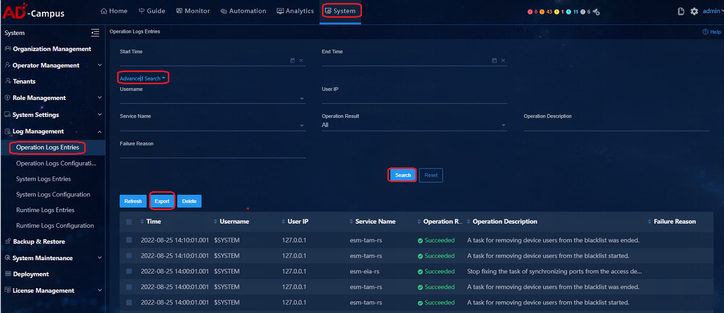
1. Log in to the Web interface of the Unified Platform from a Web browser (for example Chrome). The login address is https://ip:30000/central/, and the login username and password are admin and Pwd@12345.
2. On the home page of the Unified Platform, click the System tab on the top navigation bar. From the left navigation page, select Log Management. Select the operation log, system log, or running log menu. Select the Service Name, Start Time, and End Time to query the logs to be exported and then click Export. You can also customize the search conditions to export specified logs.
Upgrading a Unified Platform version earlier than E0607 with a SeerAnalzyer installed causes all pods of the SeerAnalyzer to be in pending state
The upgrade policy of Matrix is to remove the node from the cluster and then reconstruct it, which will lead to the removal of labels on other products. When the label for the SeerAnalyzer node is removed, pods cannot find an available node, and therefore will be in pending status. Later Matrix versions (E0607) will change the label allocation mode and the labels are allocated by the Matrix in a unified way.
Workaround:
Execute the following command in the CLI on the master node:
cd /opt/matrix/app/install/metadata/SA/scripts/
sh -x addLabelNodes.sh
Cluster anomalies and resumption
After an abnormal power-off of server cluster or abnormal switchover between the primary and secondary devices happens:
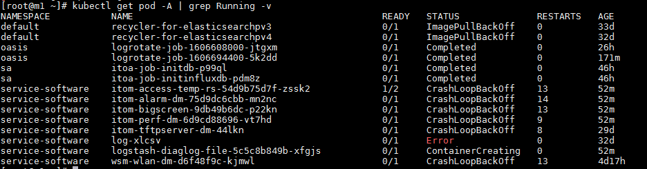
1. View the cluster status on the Installer, and verify that all pods are in running status on Monitor > Pods.
2. Execute the following command to display the pods status in the CLI:
kubectl get pod -A | grep Running -v
3. After the cluster and all pods are back to normal status, wait for 10 minutes to perform the deployment, upgrade and uninstallation of relevant components.
When an abnormal pod is detected in the background, the gfs-storage-global-diaglog with the endpoint resource of Installer is lost.
How to identify that the endpoint is lost:
You can determine that the endpoint is log if the log for the corresponding pod reports an error, and the following command's output does not contain the gfs-storage-global-diaglog field.
[root@m2 ~]# kubectl get ep gfs-storage-global-diaglog -n service-software
NAME ENDPOINTS AGE
gfs-storage-global-diaglog 20.0.1.2:1,20.0.1.3:1,20.0.1.4:1 36d
kubectl get ep gfs-storage-global-diaglog -n service-software
Error from server (NotFound): endpoints "gfs-storage-global-diaglog" not found
Use the following recovery method (as a reference):
1. Go to the directory where the YAML file is located
cd /opt/matrix/app/install/metadata/UCENTER/kernel/kernel/logs/template/compatibility
2. Execute the YAML file generating endpoint
bash ../../scripts/volume.sh update global-diaglog service-software
3. Create endpoint resources
kubectl apply -f gfs-storage-ed-global-diaglog.yaml
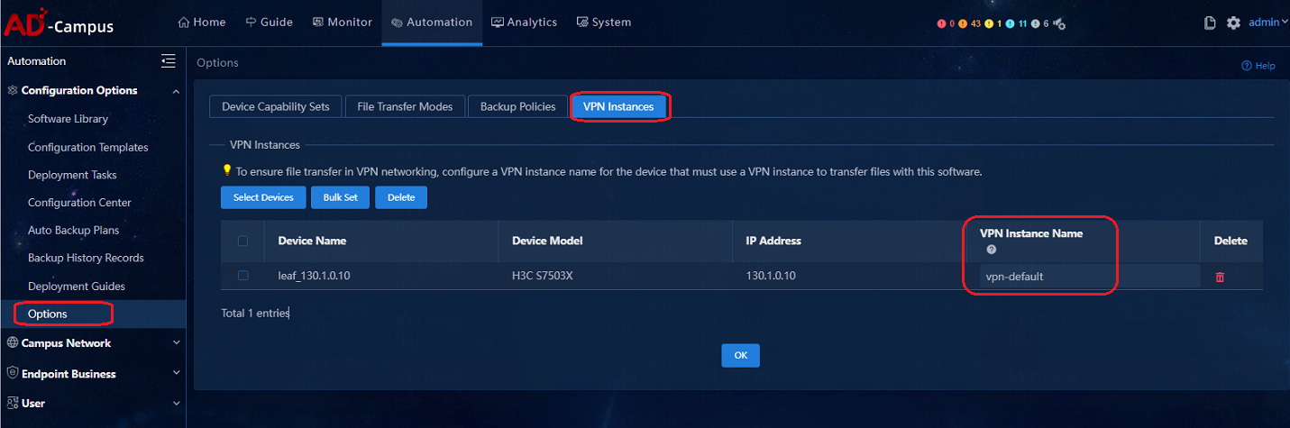
Add the vpn-default VPN instance before a software upgrade or data backup for spine or leaf devices
Avoid transmitting large files to Unified Platform during a device software upgrade
When a device is being upgraded, do not import large files from the device to the software library. If you do so, both the file import and software upgrade fail.
Resolve disk parity check failure during a component package upload
If disk parity check failure occurs when you upload a component package on the deployment management page of Unified Platform, clear the browser cache and upload the package again.
Avoid restoring data of Unified Platform across software versions
Do not restore data of Unified Platform with a data backup file that is created on a Unified Platform version different from the one in use. To restore data of Unified Platform, make sure the data backup file is created on the Unified Platform version in use. Unified Platform does not support data restoration across software versions.
Restrictions for Unified Platform deployment on a VM
· Do not use a VM snapshot for Unified Platform deployment.
· Check the server configuration guides for the solution of interest to verify the following information:
¡ Component support for VM deployment.
¡ Hypervisor requirements.
¡ Software version requirements.
¡ Hardware resource requirements.
· To deploy Unified Platform and its components on a VM managed by VMware, enable forged transmits and promiscuous mode on the host on which the VM is running. If you configure VLANs on the component networks, assign the host's network ports to all VLANs.
SeerEngine-Campus deployment
How to select network adapters when creating networks
The connection mode between Unified Platform and the switch is Layer 3 network connection.
In Layer 3 network connection mode, the management IP addresses of the controller and that of the switch are in different network segment and are interconnected via Layer 3 routing. The controller can be deployed remotely or locally. The deployment can be conducted with one or two network adapters. When one network adapter is used, the SeerEngine-Campus controller and Unified Platform share this network adapter. When two network adapters are used, the SeerEngine-Campus controller and Unified Platform each use a dedicated network adapter.
How to start up network adapters when creating networks
When SeerEngine-Campus is deployed, regardless of whether the Spine device and the controller are connected at Layer 2 or Layer 3, you need to modify the network adapter configuration file at each node server, and then execute the ifup ×××× command to start the network adapters. When the network adapters become up, the uplink interface associated with host can be selected during the network deployment.
If you only execute the ifup ××× command but not modify the configuration file for a network adapter, the Campus container cannot be created after the restart of server node. This is because in the configuration file of the network adapter, the ONBoot=NO, so the network adapter cannot turn UP after the restart of server node.
Solution:
Modify the network adapter configuration file and then execute the ifup ××× command to start the network adapter.
Modify the BOOTPROTO and ONBoot parameters in the network adapter configuration file as shown below.
Execute the # vi /etc/sysconfig/network-scripts/ ifcfg-enp61s0f1 command to edit the network adapter configuration file as appropriate.
[root@node1 ~]# ifup enp61s0f1
|
|
WARNING! Do not execute ifdown command on the network adapter. Otherwise, the default route might be removed. If the ifdown command is executed, the service restart network command should be executed to restart and resume the network. |
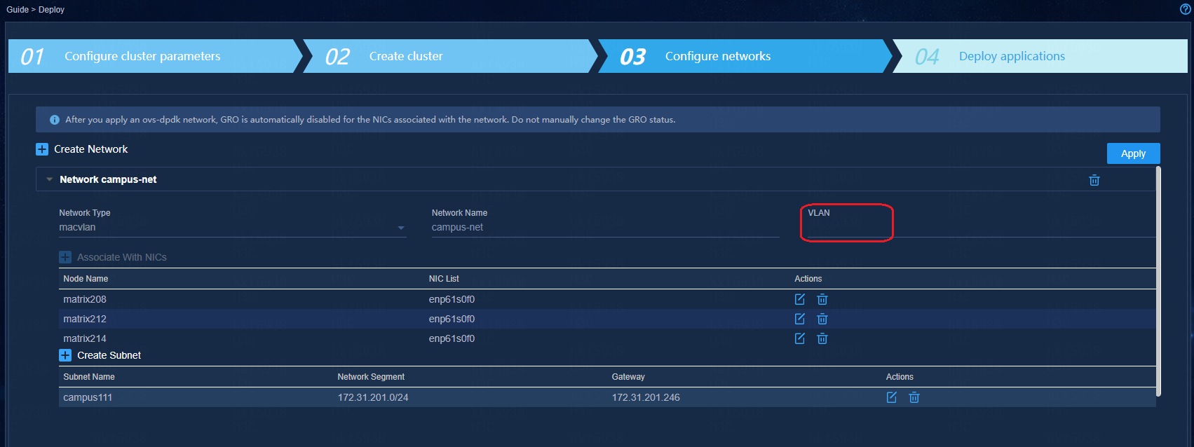
How to configure the VLAN field when creating networks
On the Configure Network page, the VLAN field is empty by default.
· If you keep the VLAN field empty: The packet sent by the server has no tag. Configure the access switch's interface connecting the server network adapter as an access interface.
· If you enter a VLAN ID in the VLAN field: The packet sent by server carries the VLAN tag (PVID cannot be the same as the configured VLAN ID. Otherwise the VLAN tag will be removed). Configure the access switch's interface connecting the server network adapter as a trunk interface.
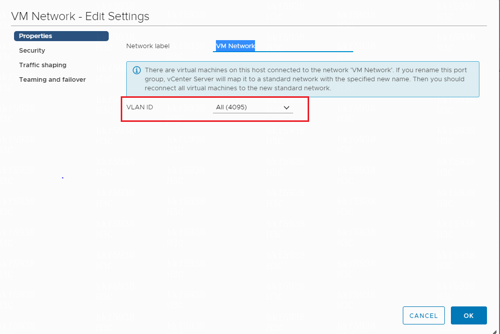
How to permit all VLANs in VMware ESXi version 6.7
To permit packets of all VLANs, enter 4095 in the VLAN ID field in the port group configuration.
Restart of the server's physical network adapter leads to the loss of default routes in all containers
The restart of a physical network adapter on a server will lead to the loss of default routes in all containers. When a server is deployed with containers, it is forbidden to restart the physical network adapter alone.
If a physical network adapter has been restarted separately, you must manually restart all the containers in the physical server or restart the server.
Restart of the network adapter in a container leads to the loss of default routes in that container
The restart of the network adapter in a container will lead to the loss of default routes in the container. If the network adapter in a container is restarted manually, you need to restart the container to restore the services by using the docker restart container name command.
When the campus ED and the data center ED are interconnected, if both sides' VCF roles are the same, one side will restart due to automatic stacking
Issue
Automatic deployment is used in converged deployment of campus and data center networks. When the campus ED and the data center ED are directly connected, if both sides' VCF roles are the same, one side will restart due to automatic stacking.
Solution
You need to manually disable the LLDP function on the ED on one side of the interconnect interface with the other side after the incorporation is completed on this side, and then connect to the ED on the other side. After all devices are incorporated, disable the automation function of the data center EDs, and at the same time, disable the LLDP function of the interconnection interfaces of all EDs by executing the following commands:
· Disable LLDP on interfaces:
interface Ten-GigabitEthernet1/2/21
undo lldp enable
· Disable the device automation function:
vcf-fabric underlay pause
Login to license server
Enter the GUI login address of the license server on a Web browser (the address format is
http://lics_ip_address:port/licsmanager/, for example http://172.16.0.227:28443/licsmanager/), and then press Enter. The login page will open.
· The lics_ip_address is the IP address of the server for license server software installation; if the HA function is already configured, the address can be virtual IP address or the IP address of primary license server.
· The port is the HTTP port number and the default value is 28443.
· The default username and password are admin and admin@h3c respectively.
Avoid connecting multiple controllers to the same license server
A license server supports only one controller.
Resolve the network fault caused by dedicated NICs of SeerEngine-Campus and Unified Platform
Issue
If Unified Platform and the campus cluster use different NICs, the SeerEngine-Campus Web interface is unavailable after a network fault occurs on a server of Unified Platform.
Cause
The campus cluster is unaware of master switchover or failure in the Unified Platform cluster. If the leader node of the campus cluster is collocated with the server that has the network fault, this issue will occur.
Solution
To resolve this issue, restore the network connection on the faulty server and restart it to trigger a master switchover in the controller cluster.
Resolve trap report failure after physical network element incorporation by SeerEngine-Campus
Issue
After incorporating a physical network element, SeerEngine-Campus sends the device information to the network monitoring list and issues a command to the device. The command is used to enable trap reporting, and it does not carry a VPN name. Spine and leaf devices are in the vpn-default VPN, and missing of the VPN name prevents the devices to report traps.
Solution
To resolve this issue, execute the following command. This issue will be resolved in future versions.
snmp-agent target-host trap address udp-domain xx.xx.xx.xx vpn-instance vpn-default params securityname public v2c
Common basic commands
The Kubectl command
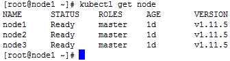
· View the node status
kubectl get node
· View the node description information, and you can see all the information of the node, including all Pod information.
kubectl describe node * --------- (* represents the node name, for example, node1)
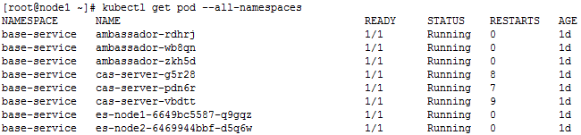
· View all pods
kubectl get pod --all-namespaces
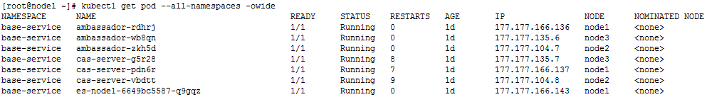
· View all pods details
kubectl get pod --all-namespaces –o wide
· View the pods of the designated namespace, for example, the base-service namespace
kubectl get pod –n base-service
· View the pods detail of the designated namespace, for example, the base-service namespace
kubectl get pod –n base-service –o wide
· Remove the pod with the specified name in the designated namespace
kubectl delete pod XXX –n XXX
For example, remove the pod named ambassador-rdhrj in the base-service namespace:
[root@node1 ~]# kubectl delete pod ambassador-rdhrj -n base-service
pod "ambassador-rdhrj" deleted
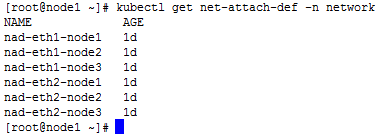
· View the names of multiple networks
kubectl get net-attach-def -n network
· View the details of the designated network
kubectl describe net-attach-def XXX -n network

The docker command
1. Execute the docker command to enter the container.
a. View the docker process, for example, view the process IDs of SeerEngine-Campus and vDHCP:
docker ps | grep campus ----Query the docker process for campus
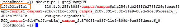
b. Execute the docker command with the specified process ID to enter the container:
docker exec -it 1f4a031a11c1 bash
![]()
2. View the CPU/memory occupied by the container.
AD-Campus services
Automated device deployment
Strong password features
The SeerEngine-Campus controllers and switches support strong password features. They require local users' passwords to meet the security requirements for classified protection:
· Contain at least 10 characters;
· Contain at least two of the following character types: numbers, uppercase letters, lowercase letters and special characters.
· Cannot contain Chinese characters, question mark (?), spaces, username, or the reversed username.
If an existing site using weak passwords is upgraded to the new environment that supports string passwords, the switch will print out the weak password information, but its functions will not be affected.
If existing sites are expanded with leaf and access devices, use switches that do not support strong password features for auto deployment as a best practice. After the deployment is complete, upgrade them to support the strong password feature. Manually deployed devices do not have this restriction.
For new auto deployment, the new controllers support modifying the local usernames and passwords in the automation templates. Modify the usernames and passwords to meet the classified protection requirements.
Devices configuration must be restored to factory defaults for automatic onboarding
For automatic onboarding or stacking of devices, configurations of the devices must be restored to factory defaults.
Restoration of the device configuration to factory defaults
For automatic deployment of devices, restore the devices configuration to factory defaults by executing the restore factory-default command.
# Restore the device configuration to factory default.
<Sysname> restore factory-default
This command will restore the system to the factory default configuration and clear the operation data. Continue [Y/N]:y
Restoring the factory default configuration. This process might take a few minutes. Please wait..........................................................................................................Done.
Please reboot the system to place the factory default configuration into effect.
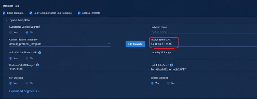
RR MAC configuration in the automatic deployment
Fill the bridge MAC address of the spine device in the RR MAC input box on the automatic deployment page.
If the spine devices are stacked, the bridge MAC addresses of the two spine devices are required.
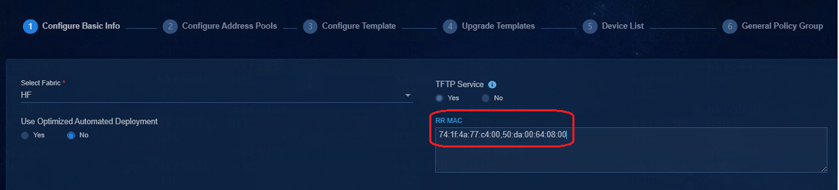
The Master Spine MAC address in the spine template must have been added to the RR MAC list, and the device with the Master Spine MAC address must be specified as the master device when it is stacked.
Avoid changing the DHCP server for automated device deployment
You must use the H3C vDHCP server for automated device deployment. To change the DHCP server in the automation template, contact H3C Support.
Query of RR MAC addresses
The bridge MAC address of a spine device can be viewed on the device side by executing a command:
· Method 1: Execute the display device manuinfo command:
[h3c]dis device manuinfo chassis 1 slot 0
Chassis 1:
Slot 0 CPU 0:
DEVICE_NAME : LSUM1SUPC0
DEVICE_SERIAL_NUMBER : 210231A4B8H174000229
MAC_ADDRESS : 60DA-8309-E000
MANUFACTURING_DATE : 2017-04-13
VENDOR_NAME : H3C
[H3C]
· Method 2: Execute the debug stack show memberinfo command in probe view:
[H3C-probe]debug stack show memberinfo chassis 1 slot 0
=============================================================
Member Information of STACK Module
=============================================================
MemID:1, LocalSlotID:0, Priority:0, Mode:90
MaxMemNum:4, MaxPortMemberPort:16, StackCapability:5
BridgeMac:60:da:83:09:e0:00
[H3C-probe]
View serial numbers of devices
· To view the serial numbers of the S10500X/S10500 series:
display license device-id chassis *
· To view the serial numbers of the S7500E series (view the serial number of the primary MPU if multiple MPUs exist):
display license device-id chassis * slot *
· To view the serial numbers of fixed-port devices (S6550XE/S6525XE/6520X/S5560X series)
display license device-id slot 1
· To view the serial numbers of the S7500X series (view the serial number of the primary MPU if multiple MPUs exist):
display device manuinfo chassis * slot *
· To view the serial numbers of fixed-port devices (S51 series)
display device manuinfo slot 1
Cascading of access devices
The cascading of access devices must use GE interfaces, and the cascading is limited to the interconnection between two physical links. This restriction does not apply to optimized automated device deployment.
Stacking of access devices
The stacking of access devices must use 10G interfaces, and the devices stacked for the same role must be the same type. The stacking interfaces on the 5130 switch series do not support inter-chip stacking. Contact H3C Support to obtain chip compatibility information.
Stacked access devices does not support BFD MAD
BFD MAD cannot be automatically deployed to the access devices in stacking mode. Manually configure BFD MAD for the devices if the BFD MAD is needed.
Fix the AP flapping issue triggered by the STP attack packets sent by clients
Issue
The APs attached to access or leaf devices will flap if clients send STP attack packets.
Solution
To solve this issue, enable BPDU filter on the AP-facing interfaces of the access or leaf devices. Those interfaces will stop sending BPDUs and ignore incoming BPDUs, no matter whether they are edge ports. With BPDU filter enabled, the device cannot negotiate STP status with peers. Before you enable this feature, make sure you are fully aware of its impact, or enable this feature only on edge ports.
<Sysname> system-view
[Sysname] interface gigabitethernet 1/0/1
[Sysname-GigabitEthernet1/0/1] stp port bpdu-filter enable
If you enable BPDU filter, the port will not send or process BPDUs and thus cannot negotiate the spanning tree protocol status with the peer. Make sure you are fully aware of the impacts of this command. As a best practice, enable BPDU filter only on edge ports.
Fix the large broadcast or multicast traffic issue on AP-facing interfaces of access or leaf devices
Issue
An AP-facing interface on an access or leaf device by default trunks all VLANs. If the upstream interfaces of the device receive dense broadcast or multicast traffic, the traffic will propagate to the AP-facing interface.
Solution
To resolve this issue, perform one of the following tasks:
· Assign an AP-facing interface only to the VLANs in the security group VLAN pool.
If you shut down the AP-facing interface, its VLAN assignment configuration will be lost. If the security group VLAN pool is edited, you must change the VLAN assignment configuration accordingly on the AP-facing interface.
· Enable IGMP snooping globally and for the VLANs transmitting the multicast or broadcast traffic if one of the downstream APs is associated with multicast or broadcast receivers.
For example:
# Enable IGMP snooping globally.
<SwitchA> system-view
[SwitchA]igmp-snooping
[SwitchA-igmp-snooping] quit
# Assign GigabitEthernet 1/0/1 through GigabitEthernet 1/0/4 to each VLAN where multicast or broadcast traffic exists. Enable IGMP snooping and dropping unknown multicast data for the VLANs.
[SwitchA]vlan 3501
[SwitchA-vlan100]port gigabitethernet 1/0/1 to gigabitethernet 1/0/4
[SwitchA-vlan100]igmp-snooping enable
[SwitchA-vlan100]igmp-snooping drop-unknown
[SwitchA-vlan100]quit
Auto deployment of devices must be conducted by level in order
The auto deployment of devices must follow the order of spine devices > leaf devices > access devices. The auto deployment of cascading access devices must follow the order of access device levels. Higher-level access devices will be brought online first.
Device version upgrade and supported file formats for upgrading
Device version upgrade via controller only supports software version upgrade (.ipe file upgrade), and does not support patch package upgrade.
Device version upgrade can be done in two ways:
· Specify a version in the automation template and the upgrade will be automatically performed during auto onboarding of devices. This upgrade method is available only for devices of the same model. For devices in different models, the software version must be selected for each model for upgrade.
· After the devices are incorporated on the controller, navigate to the Automation > Configuration Center > Software Library page. Specify devices and upgrade the device version.
Remaining capacity required for device version upgrade
To use the controller to upgrade the device version, make sure the remaining capacity of the device is larger than twice the size of the uploaded version file before performing the device version upgrade, otherwise the device version cannot be upgraded successfully. In case the version upgrade is done through auto deployment, the automation process cannot be completed.
For S7500E and S10500 devices, because the space of some MPUs is small (1 G), which cannot meet the requirements of having twice the size of the IPE file on the controller, loading versions during automatic deployment or upgrading the device versions will fail. You can manually upgrade the device versions via the bin package.
A template can be used to upgrade devices only model by model during automated deployment
During automated deployment, you can specify only one upgrade file in a role-based automation template. If multiple device models are assigned the same role, you must upgrade the devices model by model.
If a device model does not match the upgrade file specified in a template, the devices of that model will be stuck at managing state and cannot finish automated deployment. To identify this issue, execute the view /var/log/fabric.log command in probe view and verify errors for update_version.py exist.
[Access]probe
[Access1-probe]view /var/log/fabric.log
………………………………………………………………………………………………………………………………………………………………………………………………………………………………
%Aug 6 08:58:58:304 2021 Access1-T27 PKG/5/PKG_BOOTLOADER_FILE_FAILED: -IPAddr=**-User=**: Failed to executed the boot-loader file command
2021-08-06 08:45:55,609 url.py[line:62] WARNING tftp download image, require-space be estimated!
2021-08-06 08:52:30,127 update_version.py[line:201] DEBUG
copy file tftp://100.1.0.100/campus/image/S5130S_EI.ipe to /mnt/flash:/version.ipe success
2021-08-06 08:52:30,133 update_version.py[line:287] DEBUG
install slot 1 main begin
2021-08-06 08:52:33,214 update_version.py[line:297] DEBUG
boot-loader flash:/version.ipe exception: NULL result without error in PyObject_Call
2021-08-06 08:52:33,217 update_version.py[line:57] ERROR
The script is running failed!
2021-08-06 08:52:33,812 update_version.py[line:45] DEBUG
delete all files
Enable/disable whitelist in the automation template
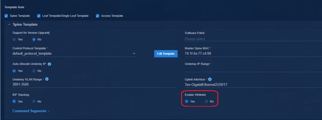
The Enable Whitelist option on the automation template:
· Yes: Whitelist is enabled. The controller examines the Device List before performing auto onboarding of devices. If a device serial number is in the Device List, the auto onboarding of the device is allowed; otherwise the auto onboarding will fail.
· No: Whitelist is disabled. The controller does not check the Device List before auto onboarding of devices. It recognizes the VCF role in the device configuration and obtains the automation template according to the VCF role to complete the auto onboarding of the device.
Whitelist verification failure during device auto onboarding
Issue
The Autoconfig phase is carried out repeatedly during the device auto deployment. The following information is displayed: VCF underlay initialization failed. Please check the system logs for detailed information.
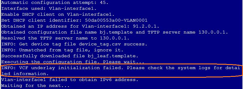
Solution
This is because the Enable Whitelist is selected in the automation template, and the device serial number is not added to the Device List before auto onboarding. Please add the device serial number to the Device List and perform auto onboarding again.
After the auto onboarding, the spine device cannot obtain the VSI4094 interface IP address
If the spine device cannot obtain VSI4094 interface's IP address after it comes online, verify the following:
· Verify that the following configuration has been deployed on the uplink interface of the spine device:
#
interface Ten-GigabitEthernet2/2/0/17
port link-mode bridge
port link-type trunk
port trunk permit vlan all
#
service-instance 4094
encapsulation s-vid 4094
xconnect vsi vxlan4094
#
· Verify that the switch connected to the uplink interface of the spine device is correctly configured. If Layer 3 access is adopted and the controller R001B01 solution version is adopted, the DHCP relay needs to be configured on the VLAN4094 interface. The R002B01 and R003B01 versions or later do not need this configuration (the controller allocates the 4094 interface IP address).
· In the automation template of the spine device, verify the correctness of the bridge MAC configuration. If the bridge MAC configuration is incorrect, the acquisition of VSI4094 interface IP address will fail.
· View the uplink interface configuration in the automation template of the spine device, the interface name must be in the following format: Ten-GigabitEthernet2/2/0/17, and no space is allowed in the interface name.

After the auto stacking, the single leaf model cannot acquire the VSI4094 interface IP address
Cause
The master device of the IRF stack is determined based on the bridge MAC address. The device with the largest bridge MAC address will be set as the master device. When the uplink interface filled in the automation template of the single leaf device is the interface of the device with a small bridge MAC address among the stacked devices, the device member ID will be modified after automated stacking. In this case, the IP address acquisition will fail, because the acquired uplink interface and the actual interface are inconsistent.
Solution
Modify the uplink interface in the automation template of the single leaf device to the actual uplink interface of the leaf device after stacking.
|
|
NOTE: In the automation template, the uplink interface must be in the following format: Ten-GigabitEthernet2/2/0/17, and no space is allowed. |
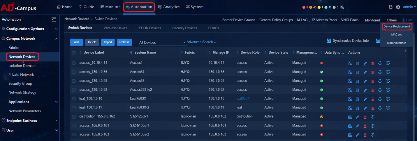
Device replacement
The automation feature of AD-Campus supports both precise replacement and heterogeneous replacement of devices.
Precise replacement means the replacement of devices based on the configuration files. It supports the replacement of the primary spine device and other devices. The replacing device and the replaced device must be the same type and the devices have the same port connections.
In heterogeneous replacement mode, the replacing device and the replaced device are not necessarily of the same type. Currently, the heterogeneous replacement is not provided on the replacement page, but manual configuration is available. Fuzzy replacement does not replace the device configuration file, but only replace the name of the device. When a device fails, change the new device's name to the faulty device's name and use the new name to come online. For automatic onboarding of the replacing device (new device), set the name of the replacing device in the Device List to the name of the faulty device. For manual onboarding of the replacing device, configure the Sysname of the device to that of the faulty device. After the replacement is completed, delete the faulty device manually.
Path: Automation > Campus Network > Network Devices > Others > Device Replacement
Collection of logs related to auto deployment
· The /var/log/fabric.log records the logs for auto deployment
Export method: execute the view /var/log/fabric.log > fabric.log command in probe view and then export the fabric.log file in flash directory.
· Export the logs in the log buffer
Execute the logfile save command in user view to export the buffered logs to the log file.
· View the underlay automation execution result
display vcf-fabric underlay autoconfig
· View the local topology
Execute the following command in probe view:
display system internal vcf-fabric topology
· Device template
xxx.template file
Process exits during the automation
A process might exit during automation due to the following:
· Version upgrade or patching failure
a. Check the log buffer for the upgrade failure information.
display logbuffer | inc VCF
b. Identify the cause of upgrade failure.
c. View the details in the fabric.log file.
· Process exceptions
To check for the process exceptions, view the details in the fabric.log file.
Interface configuration not deployed
To resolve this issue:
1. View the local topology of the device and verify the correctness of the neighbor roles.
2. Verify the correctness of the template.
3. View deployment failure logs for the corresponding interfaces in the fabric.log file.
4. Check for the configuration rollback or other forms of undo operations in the log buffer.
Automated expansion
When two devices are up for automated stacking, if the second device is deployed within 2 hours after the deployment of the first device, the deployment of the second one will be deemed as a new automated stacking. That is, the second device may be selected as the master device, while the first one may become the secondary device and lose configuration.
When the second device is deployed beyond the 2-hour limit after the deployment of the first device, the process will be deemed as automated expansion.
Stacking failure during auto deployment
1. Verify the correctness of template roles acquired by the device.
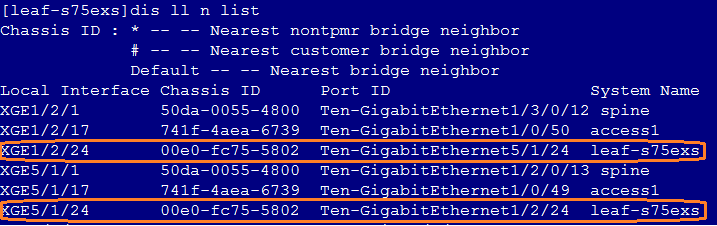
2. Execute the dis lldp neighbor-information list command under the device system view to view and verify the stacking interface in the LLDP neighbor information.
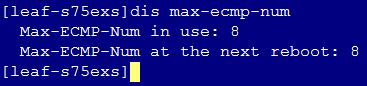
3. Execute the dis max-ecmp-num command under the device system view to verify the consistency of the max-ecmp-num in the two devices.
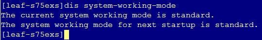
4. Execute the dis system-working-mode command under the device system view to verify the consistency of the system working modes of the two devices. (The command is supported by the devices of S105 series)
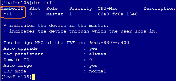
5. Execute the dis irf command under the device system view to verify the member ID. The member ID of devices joining the automated stacking must be ensured to be 1. If the member ID is not 1, execute the restore factory-default command under user view to restore the device to factory defaults.
Locate the defected phase in an auto deployment failure
1. Verify the topology to ensure that the network connected to devices of auto deployment is normal and they are interconnected with SeerEngine-Campus and vDHCP server.
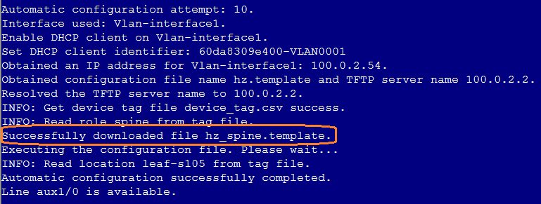
2. Execute the dir command on the device to verify the existence of the xxxxx.template files in the root directory to determine if the device has successfully downloaded the automation template from the TFTP server.
3. Execute the dis int LoopBack 0 command on the device to verify the acquisition of loopback interface address. The loopback interface address is allocated by the spine device.
4. If it is the spine device that gets automatically deployed, the deployment situation of uplink interface configuration of the spine device shall be verified.
5. Execute the dis vcf-fabric underlay autoconfigure command on the device to view the automation commands executed by the device, the VLAN and the device interface configuration deployment, the int VSI4094 interface configuration deployment and IP address acquisition, and other information such as BGP configuration to determine the automation process.
6. Log in to the Unified Platform management page to view the incorporation of devices.
7. View the corresponding VLAN1/VSI4094 interfaces to determine the static device IP address.
8. Log in to the vDHCP to view the IP address binding of VLAN1/VLAN4094 interfaces.
When the device is automatically deployed, its status will remain as managing
1. Navigate to Automation > Campus Network > Fabrics > Auto Deployment > Auto Device Deployment Tasks to view the device automation process.
2. View the cause for automation failure.
3. If the cause is failed to obtain device serial number, execute the following two commands on the devices to verify the consistency of the device serial numbers.
display device manuinfo chassis * slot *
display license device-id chassis * slot *
4. If the device serial numbers returned from the two commands are different, add the device serial numbers returned to the Device List of the controller and perform the device auto deployment again.
5. If the device serial numbers returned from the two commands are identical, contact Technical Support for help
MAD restrictions for access device stacking
The auto deployment of BFD MAD is not supported for stacking of access devices; manual configuration is required if the BFD MAD is needed. Steps:
1. After successful stacking of devices, ensure that the physical interfaces of the BFD is down and the stacked access device configures the BFD on the physical interface.
#
vlan 100 //Dedicated for BFD MAD
#
#
interface GigabitEthernet1/0/20
port link-type trunk
undo port trunk permit vlan 1
port trunk permit vlan 100
undo stp enable
stp edged-port //Without this command, controller will audit differences
undo lldp enable
#
#
interface GigabitEthernet5/0/20
port link-type trunk
undo port trunk permit vlan 1
port trunk permit vlan 100
undo stp enable
stp edged-port //Without this command, controller will audit differences
undo lldp enable
#
#
interface Vlan-interface100
mad bfd enable
mad ip address 192.168.100.1 255.255.255.0 member 1
mad ip address 192.168.100.5 255.255.255.0 member 5
#
2. Interconnect the BFD physical wires to verify the normal status of the BFD MAD
[5130s-hi-down]disp mad verbose
Multi-active recovery state: No
Excluded ports (user-configured):
Excluded ports (system-configured):
IRF physical interfaces:
Ten-GigabitEthernet1/0/25
Ten-GigabitEthernet5/0/25
BFD MAD interfaces:
Bridge-Aggregation1022
Bridge-Aggregation1024
GigabitEthernet1/0/2
GigabitEthernet1/0/20
GigabitEthernet5/0/1
GigabitEthernet5/0/20
Ten-GigabitEthernet1/0/26
Ten-GigabitEthernet5/0/26
Vlan-interface100
MAD ARP disabled.
MAD ND disabled.
MAD LACP disabled.
MAD BFD enabled interface: Vlan-interface99
MAD status : Normal
Member ID MAD IP address Neighbor MAD status
1 192.168.100.1/24 5 Normal
5 192.168.100.5/24 1 Normal
Topology changes might result in deletion of interface configuration
Topology changes might result in deletion of interface configuration after the following events:
1. A device is configured through ADCampus automated deployment.
2. Automated deployment is suspended.
3. The network topology for the device is modified.
4. Automated deployment is enabled.
To avoid this issue, make sure automated deployment is enabled when you change the network topology.
The port with the lowest bandwidth is not selected for MAD link setup on an automatically deployed IRF fabric
Issue
The port with the lowest bandwidth can be selected for MAD link setup on an automatically deployed IRF fabric only if the port comes up within 1 minute after IRF ports come up. If this requirement is not satisfied, a random interconnect port is selected for BFD.
Solution
To avoid this issue, suspend automated deployment, configure BFD MAD, and save the running configuration.
The Web interface of the controller is unavailable after transient loops appear in the management network
Issue
Transient loops might appear in the management network if the management network is not set up correctly.
Solution
To resolve this issue, execute the kubectl delete command to restart dns and portal containers.
Device resources incorporation
After the device is incorporated, there are configurations not deployed successfully
Issue:
Log in to the Campus Management
page. If the Data Synchronization Status of the device is ![]() , it indicates that some of the
configurations are not successfully deployed.
, it indicates that some of the
configurations are not successfully deployed.
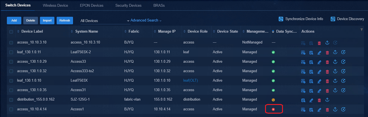
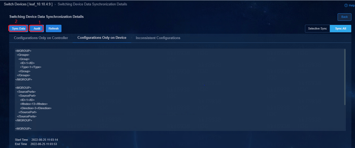
Solution:
Click ![]() to
go to Switching Device Data Synchronization Details page. Click Audit
and the audit results will be displayed in the .xml file, and click Sync
Data to synchronize the inconsistent info between the controller and the
device. The controller will synchronize the configurations that are not
deployed to the device.
to
go to Switching Device Data Synchronization Details page. Click Audit
and the audit results will be displayed in the .xml file, and click Sync
Data to synchronize the inconsistent info between the controller and the
device. The controller will synchronize the configurations that are not
deployed to the device.
Devices auto-deployed after a stack split cannot be incorporated
Issue:
For device stacking after auto deployment, the (spine and leaf) devices experiencing auto re-deployment of backup frames after stacking split cannot be incorporated.
Solution:
When stacking devices are separated for operations, the network elements on the page must be removed manually before the auto deployment of the devices.
Devices states on the controller are Inactive after the devices in a stack perform a master/subordinate switchover
Issue:
During the primary/secondary switchover between stacking devices, the device status of the controller will be displayed as inactive for a while, yet, the device status will be resumed as active later
Cause:
Controller fulfillment: After the controller and the OpenFlow device are successfully established, the controller will also establish a NETCONF long connection with the device and deploy the configuration to the device through NETCONF. As long as either of NETCONF connection or OpenFlow connection is broken, the controller device status will be displayed as inactive.
Cause: The NETCONF is not equipped with the NSR mechanism during the primary/secondary device switchover, and the NSR mechanism of OpenFlow only supports the primary/secondary device switchover scenario of device with two MPUs. (Currently the OpenFlow products are defected and it is complicated to add NSR mechanism on NETCONF)
Multiple controllers cannot manage the same device
A device can be managed by one device.
A compatible Huawei device is inactive after incorporation
Issue
A compatible Huawei device is inactive after incorporation because of SNMP connection failure.
Solution
To resolve this issue, include the mib-view keyword in SNMP parameters.
snmp-agent
snmp-agent community read read
snmp-agent community write cipher write mib-view iso-view //Configure community names based on your environment
snmp-agent community read cipher public mib-view iso-view //Configure community names based on your environment
snmp-agent sys-info version all
snmp-agent mib-view included iso-view iso
General policy groups
The general policy groups created manually cannot be configured with the default system group policy
Issue:
The manually created general policy groups (interface groups or device groups) can only select a user-defined policy template when a group policy is configured.
Solution:
The cause is that the default policy template only supports the general policy groups created by the system, and manually created general policy groups are not supported. The customized policy template supports the general policy groups created by the system, and manually created general policy groups. Therefore, the customized policy can be delivered to the manually created general policy group policies.
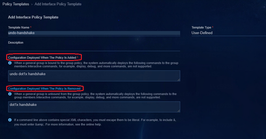
The following is an example of configuring a customized template for an interface group: select User-Defined for Template Type, fill in the input box for Configuration Deployed When The Policy Is Added with the command to be delivered to the device. In the Configuration Deployed When The Policy Is Removed box, fill in the command to restore the configuration when the policy is removed, which is required; otherwise, the configuration deployed when the policy is remove cannot be deleted.
When the AAA policy template is modified, the MAC Portal user authentication cannot succeed
When the AAA policy template is modified, click OK, and a prompt to apply the policy to general policy groups is displayed. Select Yes, and the modified policy can be delivered to devices.
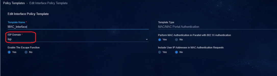
When the ISP domain name is modified in the AAA policy, the domain name in the MAC Portal interface policy template also needs to be modified, and the general policy groups to which the MAC Portal interface policy template is applied also need to be deleted and reconfigured; otherwise, the domain name configured for the interface and that in the AAA policy are inconsistent, and MAC authentication will fail.
Authentication method of an 802.1X device policy template (LDAP scenario)
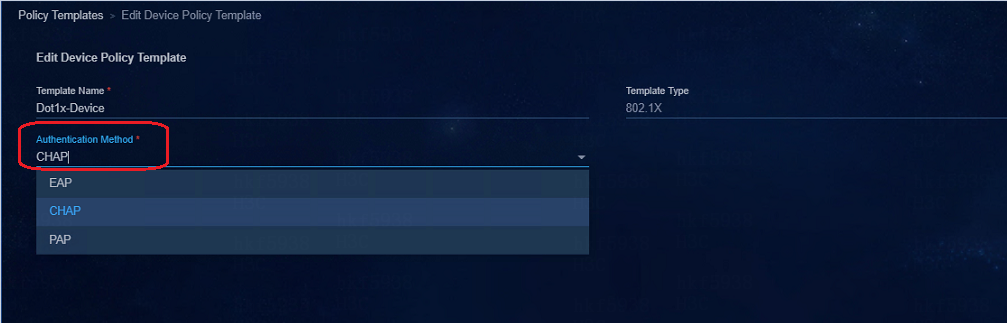
Please use the EAP method in an 802.1x type device policy template to be used for the LDAP authentication scenario.
Security groups
Private networks and security groups are not deployed to devices
Issue
The private network and security groups are created, but the configurations are not deployed to the devices, and the configuration info cannot be viewed on the device.
Solution
· Navigate to the Automation > Campus Network > Campus Network page to verify the configurations of the fabric.
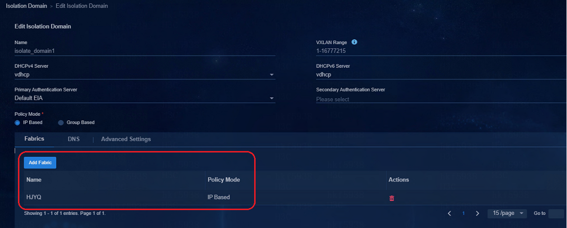
If the fabric is not configured in the isolation domain, the configurations of the private network and security groups cannot be deployed to the devices.
· Navigate to the Automation > Campus
Network > Network Devices page to
verify that the data synchronization status of the devices is ![]() . If
the status is
. If
the status is ![]() , it means that there are configurations not deployed to the devices
from the controller. Click
, it means that there are configurations not deployed to the devices
from the controller. Click ![]() to go to Switching Device Data Synchronization Details page.
Click Audit and the audit results will be displayed in the .xml file,
and click Sync Data to synchronize the inconsistent info between the
controller and the device. The controller will synchronize the configurations
that are not deployed to the device.
to go to Switching Device Data Synchronization Details page.
Click Audit and the audit results will be displayed in the .xml file,
and click Sync Data to synchronize the inconsistent info between the
controller and the device. The controller will synchronize the configurations
that are not deployed to the device.
Subnets are configured in security groups but the subnet IP address pools are not created on the DHCP server
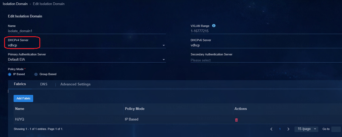
· Navigate to the Automation > Campus Network > Isolation Domain page to verify that the DHCP server is selected. The subnets of the security groups can be created on the DHCP server only when the DHCP server is set in the isolation domain.
· When the DHCP server is set, log in to the DHCP server to verify that the DHCP server is operating properly.
Switching DHCP servers for the subnets of security groups
Navigate to the Automation > Campus Network > Isolation Domain page to change the DHCP server in the isolation domain. After the DHCP server is changed, the IP address pool of the original DHCP server removes all subnets in the security groups corresponding to the isolated domain, and all corresponding subnets are created on the new DHCP server.

Secondary subnets usage restrictions
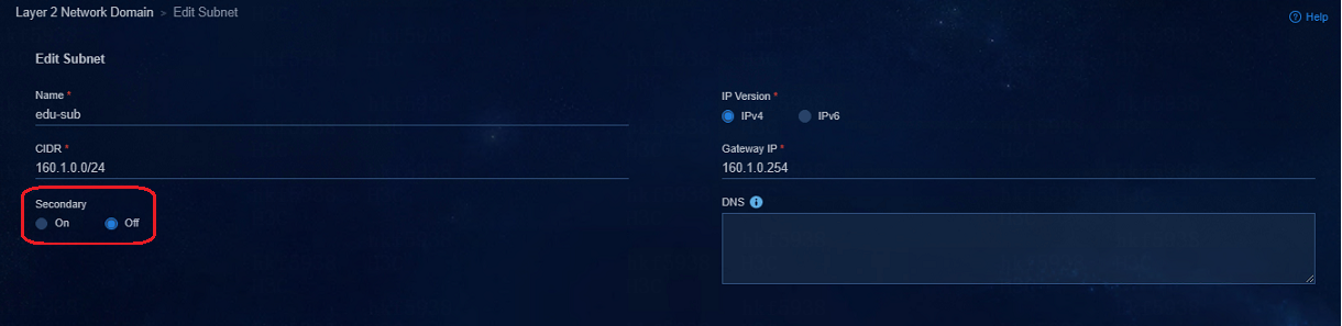
· A security group can be configured with multiple secondary subnets, but only one primary subnet can be configured. IP addresses are set according to the IP plan of the actual solution, and different security groups need to be configured with different IP address segments.
· Before the secondary subnets are configured, a primary subnet is required.
· When a secondary subnet is used, the function of "Bind Dynamically Assigned IP" cannot be used in the access policy.
· The primary subnet cannot overlap with a secondary subnet. This feature is mainly used in scenarios in which the addresses of endpoints (printers) remain unchanged when endpoints are moved. The subnets of the endpoints are added into one security group to save ACLs for inter-group policies on the device.
Inter-group policies
Access to IT resources when inter-group policies use the global Deny as default action
The default global Deny configuration for inter-group policies is shown below:
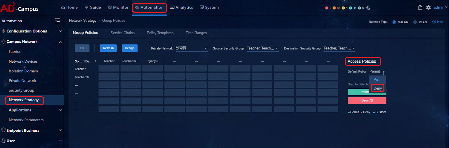
For users can access IT resources, connect physical servers in the IT resource groups to the spine devices and deploy them in the vpn-default private network. All private networks by default are allowed to visit all IT resource groups. By forbidding access to IT resource groups for each private network and deploy inter-group policies used to deny communication, you can limit the access of users to IP resources.
Broadband IoT
Keeping broadband IoT endpoints online
Issue:
Some dumb endpoints (for example, printers) that do not actively send packets, will get offline due to timeout in the absence of business for a long time
Solution:
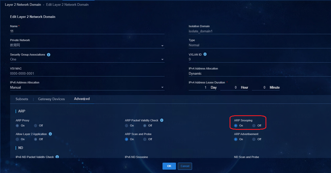
1. The main purpose of configuring the ARP Snooping enable command under VSI is to periodically send ARP requests to endpoints to verify that the endpoints are online. Currently the ARP Snooping enable command is deployed by default.

After configuration, the following configuration will be deployed to the corresponding VSI instances on the leaf devices:
#
vsi vsi5
arp snooping enable //The controller deploys the command
flooding disable all all-direction
vxlan 5
evpn encapsulation vxlan
mac-advertising disable
arp mac-learning disable
route-distinguisher auto
vpn-target auto export-extcommunity
vpn-target auto import-extcommunity
dhcp snooping binding record
#
2. On the EIA Management Control page, navigate to the Automation > User > Access Service > Access Policy page to change the Offline Check Period (Hour) in the access policy and one hour is the minimum Offline Check Period. As a best practice, set the period to 24 hours.
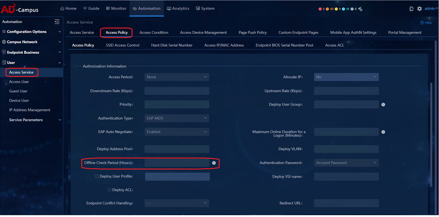
After the Offline Check Period is configured, it is ensured that in this period, users will not get offline even though the traffic volume of the user is zero. Users only need to ensure that there is traffic at the endpoint during this period (whether it is sent by the endpoint actively or in response to others), which will trigger the timing again, thereby keeping the dumb endpoint online permanently.
If it cannot be ensured that there is traffic at the endpoints during that period, you need to configure the offline-detect command and the arp-snooping command linkage by MAC. In addition to the previous ARP Snooping and offline duration configuration, you also need to manually configure the following command (mac-authentication offline-detect mac-address xxxx-xxxx-xxxx timer xxxx check-arp-or-nd-snooping) Realize the linkage between offline check period and ARP/ND snooping, actively triggering the update to keep it active by the leaf device 30s before the aging of the ARP/ND. Timer means the offline check period. As a best practice, set the aging period of proportional ARP, for example 3600s.
|
|
NOTE: Each endpoint needs to be configured with one command. The MAC address of the endpoint is filled in the mac-address blank. Otherwise, if the offline check period is the only thing to be configured, the ARP Snooping and offline check period linkage cannot be fulfilled. The endpoint will get offline when there is no triggering of traffic for the offline check period. |
Device related
Configure a static route on an external connection device
An external connection device means the intermediate switch connecting the spine device and the server (SeerEngine-Campus and EIA). After the user passes authentication, it obtains the security group address. The address obtained by the user must be able to communicate with the EIA server. To ensure this, configure a default route with the nexthop address being the spine vsi4094 interface address.
ip route-static 0.0.0.0 0 110.0.1.41
Configure IRF bridge MAC persistence
Configure IRF bridge MAC persistence, so that the IRF bridge MAC always remains the same regardless whether its master leaves the IRF or not. (Persistent by default for BCM models, non-persistent by default for Marvell models)
irf mac-address persistent always
The following questions shall be avoided on the current network:
IRF device bridge MAC can change when its master leaves. The controller receives SNMP packets from the devices every 20 seconds, parses the packets to obtain IP addresses and corresponding MACs, and compares the obtained MACs with the MACs recorded in the controller when the devices are online. The IP address conflicts will be reported when the MAC addresses are inconsistent.
VXLAN mode modification on the S5560/S6520X series
Each device must ensure that switch-mode is VXLAN MODE before it can be incorporated in SeerEngine-Campus.
The default switch-mode of the S5560X/S6520X series is NORMAL MODE, and you need to set the switch-mode to VXLAN MODE. After setting, reboot the device.
The configuration commands are as follows:
#
[leaf-s56]switch-mode ?
0 NORMAL MODE(default)
1 VXLAN MODE
2 802.1BR MODE
[leaf-0.5]switch-mode 1
Reboot device to make the configuration take effect.
[leaf-0.5]dis switch-mode status
Switch-mode in use: VXLAN MODE.
Switch-mode for next reboot: VXLAN MODE.
#
After restart, the spine and leaf devices do not have ARP entries for the EIA server or access device
Issue
After a spine or leaf device restarts, the spine or leaf device does not have an ARP entry for the EIA server or the access device. As a result, the leaf device cannot access the EIA server or the controller cannot connect to the access device.
Solution
Execute the ARP proxy-send enable command on the VSI 4094 interface of the spine and leaf devices to enable the ARP request proxy function.
The configuration is as follows:
#
interface Vsi-interface4094
ip binding vpn-instance vpn-default
ip address 100.0.1.43 255.255.255.0
local-proxy-arp enable
arp proxy-send enable
#
The status of the incorporated devices on the controller is inactive
To resolve this issue:
1. If the spine devices communicate with the controller over a Layer 2 network, verify that the spine devices have ARP entries for the controller and execute the ping -vpn-instance vpn-default command to verify that the controller is pingable.
2. If the spine devices communicate with the controller over a Layer 3 network, verify that the spine devices have ARP entries for the next hops of the routes used for reaching the controller. Execute the ping -vpn-instance vpn-default command to verify that the next hops are pingable.
3. If ARP entries are missing and the controller is not reachable, the reason might be that the spine or leaf devices have rebooted. In this condition, leaf or access devices do not have ARP entries for reaching the controller, leaf devices cannot access the EIA server or the controller, and access devices cannot reach the controller.
To resolve this issue, execute the arp proxy-send enable command on the VSI interface 4094 of spine and leaf devices.
###############################################################
As from Comware V700R001B70D046, the arp proxy-send enable command is supported .
###############################################################
#
interface Vsi-interface4094
ip binding vpn-instance vpn-default
ip address 100.0.1.43 255.255.255.0
local-proxy-arp enable
arp proxy-send enable //Enable ARP request proxy to ensure server connectivity to leaf and access devices. It must be executed on VSI interface 4094 of leaf and spine devices.
4. Check the ARP table on the L3 switch connected to the spine uplink interface. Make sure the ARP entries for the spine device, leaf device, access device, and the server exist on the L3 switch.
Dedicated egress router for interconnection of multiple fabrics
Multiple fabrics share a Layer 3 management switch as a management device of the controller. To interconnect the fabrics, configure a dedicated egress router.
Firewall
Permit port numbers and service subnets
If you use a non-standard topology, especially a topology involving firewalls, please refer to the port matrix documents of the products to permit the corresponding ports. Permit the subnets that require connectivity between one another, such as user subnets and the subnet accommodating EIA, DHCP, and DNS servers.
DNS server
After you configure DNS, verify connectivity between the BYOD subnets (for endpoints accessing the network for the first time), service subnets (for endpoints to access the network when transparent authentication is ineffective), and the subnet accommodating the DNS server. If this requirement is not satisfied, endpoints will not be redirected to the MAC portal authentication page.
User onboarding service
An access user is created, but the user is shown as not existed during authentication
Issue
The access user is created, but the user authentication fails because the user does not exist.
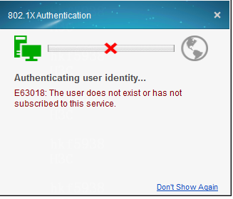
Navigate to the Analysis > Access Analysis > Authentication Failure Log page to view the log, which indicates the user does not exist either.
Solution
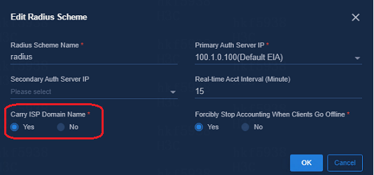
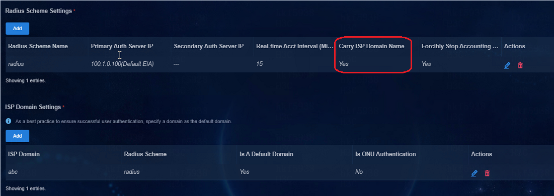
Navigate to Automation > Campus Network > Network Devices > General Policy Groups > Policy Template.
In the policy template, select Yes for Carry ISP Domain Name, meaning that the leaf device will carry username@domain in the RADIUS packets during the interaction with the EIA. This example uses IPS domain abc.
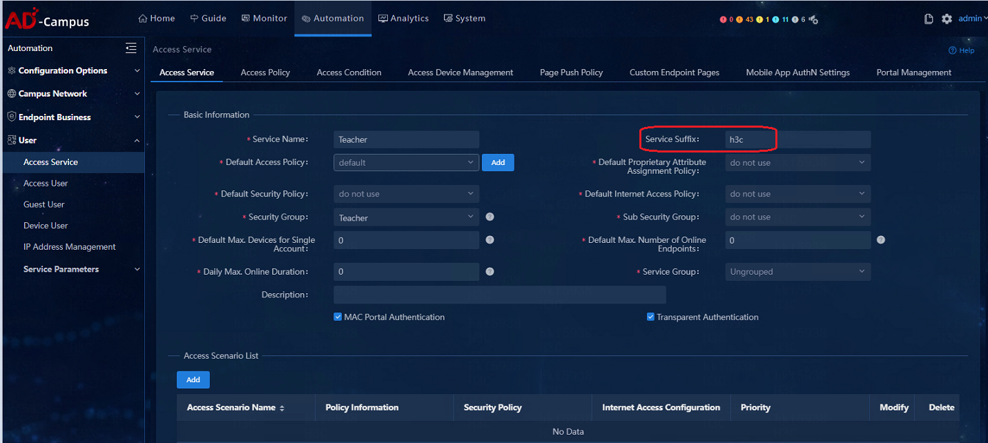
On the EIA management and control page, navigate to the Automation > User > Access Service page to change the access service. Fill in the previously configured IPS domain "h3c" in the input box of Service Suffix. In subsequent authentications of the user, the username@domain will be carried in the authentication packets automatically.
Authentication with iNode client fails
Issue
A user whose logs in by using an iNode client will be log out quickly. Error messages of Security authentication failed and No response is received from the server, and you will be forced to log off are displayed, as shown in the figure below:
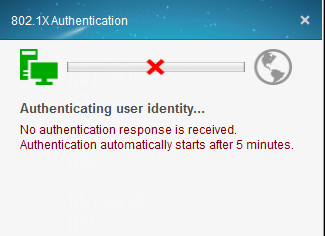
Solution
The cause for Security authentication failed is that iNode client requires EAD security authentication with EIA after the user is authenticated. The response packet from EIA is not received by user IP address. This is due to the problem of the interconnection between the IP address acquired by users and the EIA, which can be solved with the following steps:
1. Ping the EIA server address on the client side, then log in through iNode for user authentication to verify that the user can ping through the EIA after the IP address is obtained. If it cannot be pinged through, proceed to the next step.
2. Log in to the EIA server and verify that the EIA server is configured with a default route or a gateway. If so, proceed to the next step.
3. Log in to the intermediate switch where the spine device and the server (SeerEngine-Campus and EIA) are connected and verify that the next hop of the default route points to the VSI4094 interface of the spine device. If the static route does not exist, configure the static route and then try to log in again.
The static route configured on the switch is as follows:
ip route-static 0.0.0.0 0 110.0.1.41 ——The next hop of the default route is the address of the VSI4094 interface of the spine device .
4. If the issue persists, it is required to capture packets on devices to identify where the packets are lost.
Capture packets on the EIA server first. If EIA has received the client packet and has replied, capture packets on the switch that connects the spine device and the EIA server. If no packets are lost on the switch, capture packets on the spine, leaf, and access devices to identify the device on which packet loss occurs.
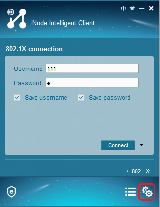
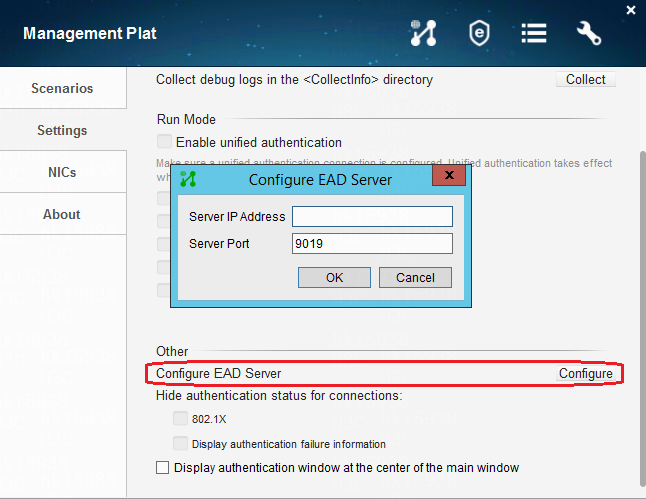
When EAD is not deployed on the EIA, the iNode client cannot configure the EAD server IP address
When EAD is not deployed on the EIA, do not configure the IP address of the EAD server on the iNode client. Otherwise, the user authentication will fail because the EAD server IP address cannot be reached.
The configuration path for the EAD server IP address on iNode is as follows:
Possible causes for user login authentication failures
Common causes for user login authentication failures include the following:
· The configuration of the AAA policy is not deployed to devices. The authentication server in the AAA policy configuration is incorrect.
· The spine device and leaf device cannot communicate with the EIA authentication server.
· The IP address of the authentication server specified when installing and deploying EIA is incorrect. The correct IP address is that of the network adapter used by EIA to provide external services.
· The authentication interface configuration on the leaf device is incorrect.
· The default route on the intermediate switch that connects the spine device and the servers (SeerEngine-Campus and EIA) does not exist or is incorrect. The next hop of the default route or detail route must point to the VSI4094 interface of the spine device.
Authentication with a non-H3C client fails
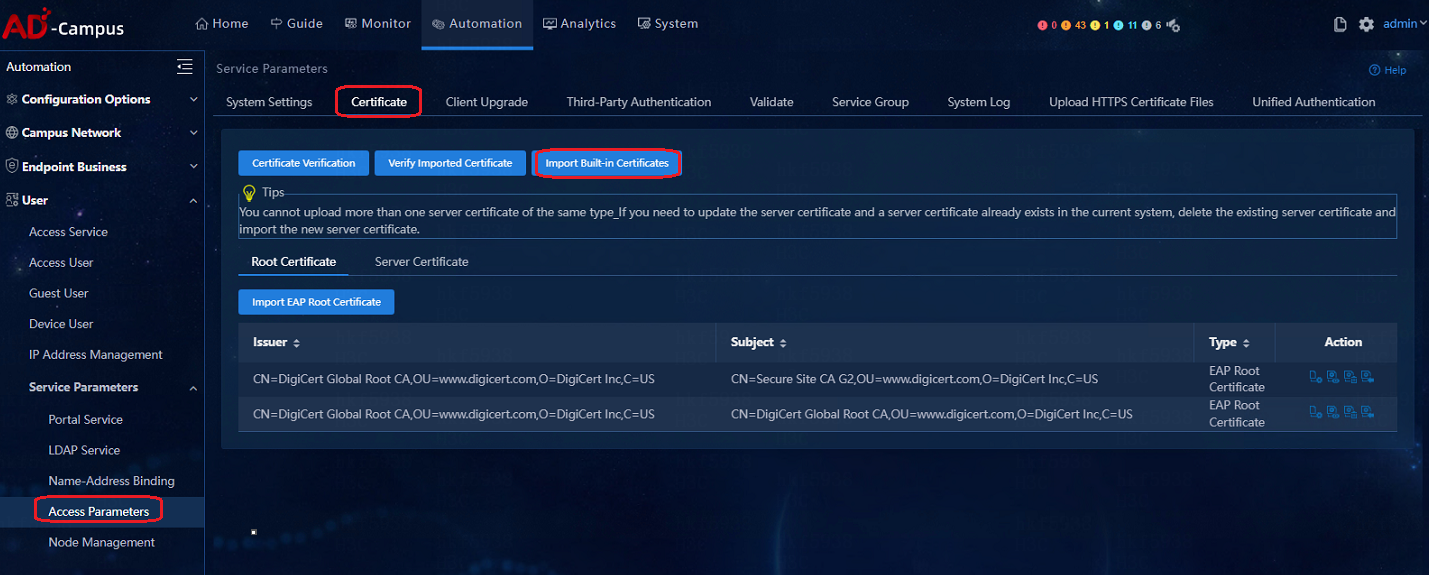
When the 802.1X authentication is carried out on non-H3C clients (such as default client on Windows, default client on Apple, or other third-party clients), built-in certificate is required. The certificate is required to be installed on the EIA control console. After the certificate is installed, the Window 802.1X client or mobile phone wireless client can pass authentication successfully.
If the certificate is not imported, the EIA will respond reject, resulting in authentication failure. The corresponding UAM debug logs are as follows:
%% 2019-09-05 10:42:57.089 ; [LDBG] ; [26740] ; EAP ; EapTlsAuth.reGenContxt: certificate file type is PEM.
%% 2019-09-05 10:42:57.089 ; [ERR] ; [26740] ; EAP ; EapTlsAuth.reGenContxt: certificate file does not exist.
%% 2019-09-05 10:42:57.089 ; [ERR] ; [26740] ; EAP ; eapProc.typeLoad: fail to init for peap.
%% 2019-09-05 10:42:57.089 ; [ERR] ; [26740] ; EAP ; EapProc.typeSelect: can't load instance for type 25.
%% 2019-09-05 10:42:57.089 ; [WARN] ; [26740] ; EAP ; eapProc.auth: typeSelect returns 1 with ErrCode 0.
%% 2019-09-05 10:42:57.089 ; [ERR] ; [26740] ; EAP ; eapTsk.sv: calling auth failed, process request failed or request invalid, simply reject.
Navigate to Automation > User > Service Parameters > Access Parameters > Certificate. On the Certificate page, click Import Built-in Certificate and the built-in certificate will be imported automatically, as shown in the figure below. After the configuration is completed, the 802.1X authentication of non-H3C iNode clients can be successful.
If users need to use their own certificate, click Import EAP Root Certificate or Import WAPI Root Certificate.
IP address binding fails
If a user successfully logged in but the user IP address binding fails, troubleshoot this issue as follows:
· Verify the converged EIA is selected during controller deployment. If this feature is disabled, proceed to the following tasks.
· Navigate to the Automation > User > Access Parameters > System Settings > User Endpoint Settings to verify that the controller IP address on the Director Controller Configuration page is correct.
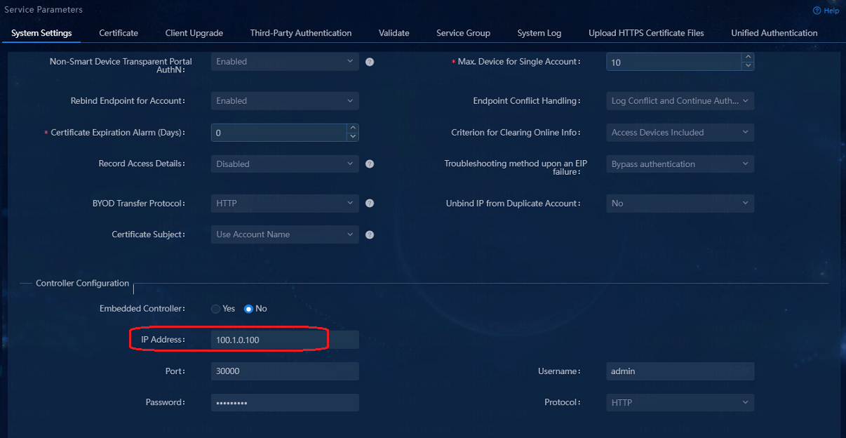
The cluster northbound IP address is filled in the IP address blank of the Controller Configuration. That is the northbound IP address configured during the cluster configuration of the Unified Platform.
The following figure shows the cluster configuration of the Unified Platform:
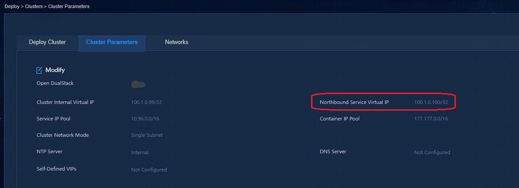
· The cluster northbound IP address pinged through on the EIA server must be interconnected with the cluster IP address.
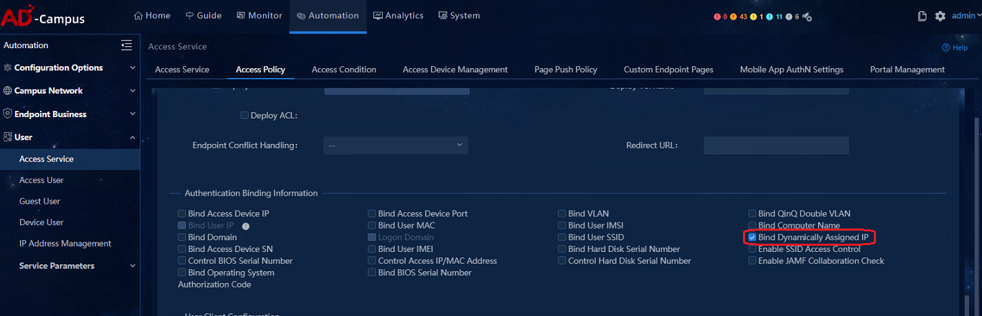
· Navigate to the User > Access Service > Access Policy page to view the corresponding access policies of the user access group, and verify that the Bind Dynamically Assigned IP is selected.
Upload IP addresses after users with static IP logged in
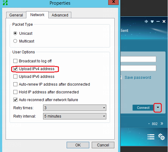
· If the iNode client is adopted, select Upload IPv4 address on the iNode client.
For MAC authentication users, enable ARP Snooping in the Layer 2 network domain.
|
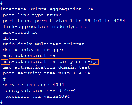
|
NOTE: The mac-authentication carry user-ip command can be configured only in scenarios of EIA static IP binding and IP segment-based automatic account opening for broadband IoT dumb endpoints. It cannot be configured in other scenarios. |
Authentication page cannot open on MAC Portal authentication endpoints
If the Portal page does not open when you enter an IP address in a Web browser, troubleshoot from the following aspects:
· The endpoint and server cannot communicate with each other.
· The redirection URL is not deployed or is deleted.
· The packet does not match the redirection URL.
After you configure DNS, verify connectivity between the BYOD subnets (for endpoints accessing the network for the first time), service subnets (for endpoints to access the network when transparent authentication is ineffective), and the subnet accommodating the DNS server. If this requirement is not satisfied, endpoints will not be redirected to the MAC portal authentication page.
The endpoint and EIA server cannot communicate with each other
If the IP address cannot be pinged, the authentication page cannot pop up.
Verify that the DHCP address acquired is in the BYOD VSI segment and the gateway is correct:
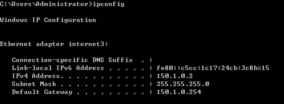
If the DHCP address or the gateway is wrong, execute the ipconfig /release command and the ipconfig renew command to release and reacquire the address on the PC:
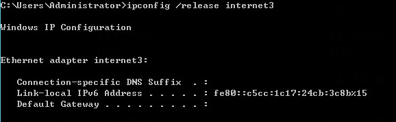

Verify that only one default route exists on the PC. Delete redundant default routes by executing the route delete command.
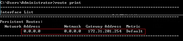
Verify that the user PC can learn the gateway ARP and the gateway can be pinged:
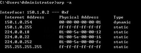
Verify that the leaf gateway can ping and the EIA server:
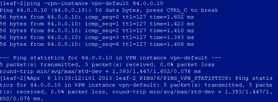
Verify that the user is online on the leaf device and the corresponding dynamic AC is created:
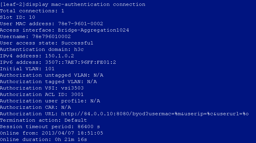
The dynamic AC on the leaf device created for the login user is as follows:

The corresponding ACL of the dynamic AC is as follows:
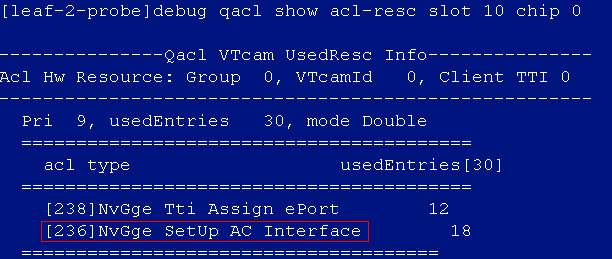
![]()
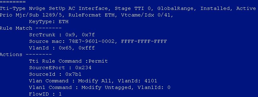
Verify that the user MAC and ARP entries on the leaf device are correct:
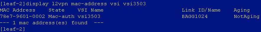
![]()
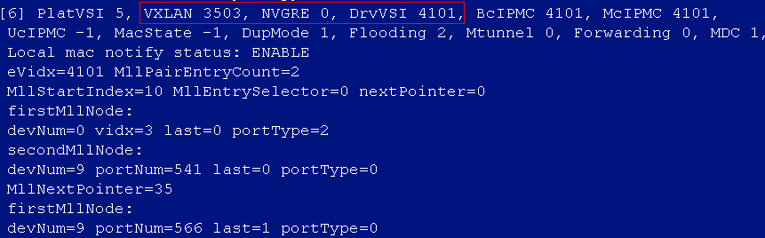
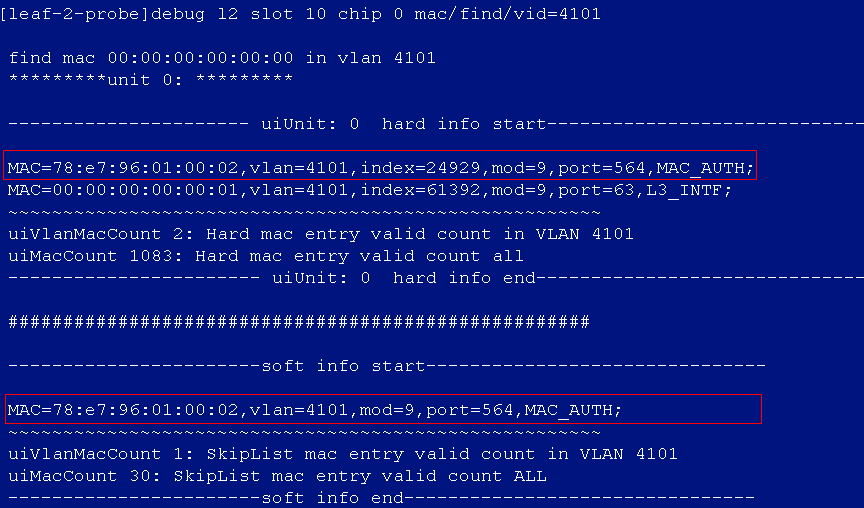
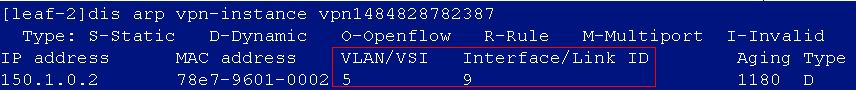
In the ARP entry, the correlation between the VSI/Link ID and the actual VSI/Interface can be verified by executing the following command:
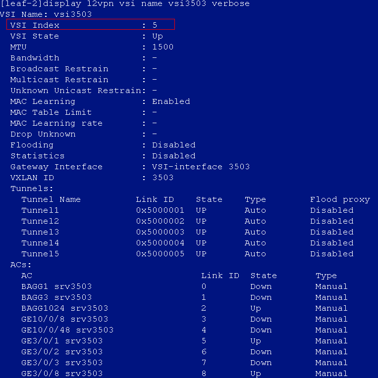
![]()
Underlay ARP entry:
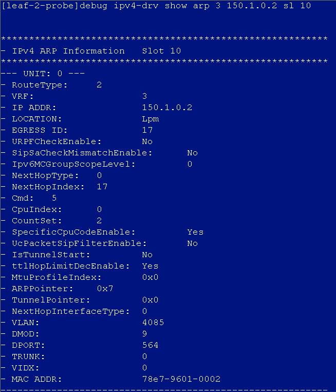
The VPN index 3 can be verified by executing the following command:
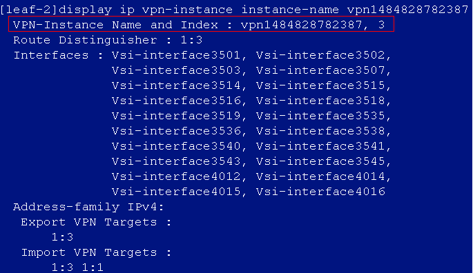
The redirection URL is not deployed or is deleted
Verify that the redirect URL exists.
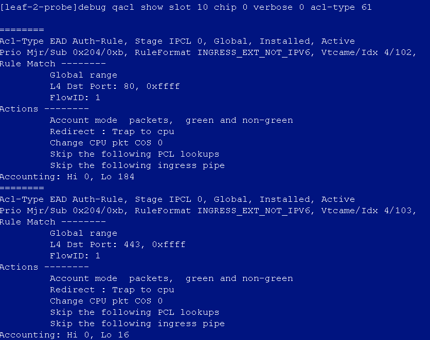
The packet does not match the redirection URL
Verify that the packets can match the redirect URL. Visit websites from the user PC, and then check whether the accounting count for redirect ACL increases. If the count does not increase, the packets do not match the redirect URL.
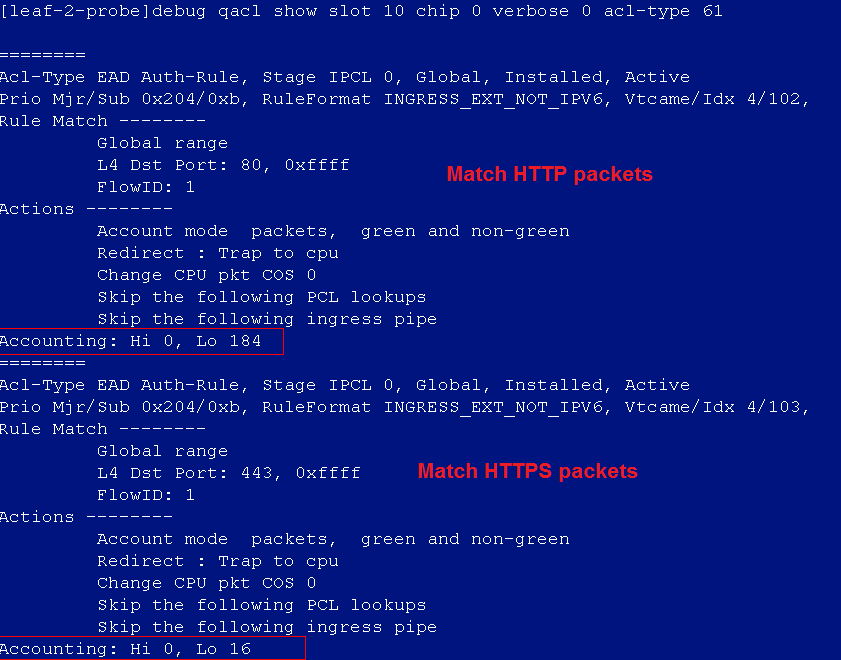
For further troubleshooting, verify that the created dynamic AC on the leaf device is correct after the user logged in. If the corresponding ACL of the dynamic AC does not have the FlowID field, or the FlowID field in the corresponding ACL is not 1, the HTTP/HTTPS packets cannot match the redirect URL.
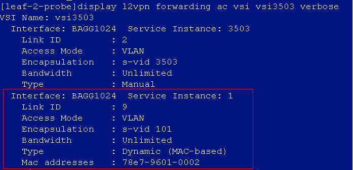
![]()
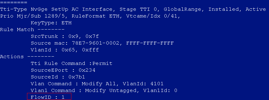
DHCP address cannot be obtained after user login
If you capture packets and find that the cause for this issue is that the leaf device did not properly forwarded the DHCP packets, perform the following to resolve the issue:
1. Log in to the DHCP server to verify that the DHCP server is normal.
2. On the leaf device, verify that the leaf device can ping the DHCP server.
3. If the leaf device can ping the DHCP server, verify that the DHCP relay configuration is deployed.
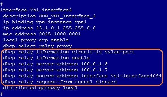
4. Verify that the dhcp enable command has been configured on the leaf device.
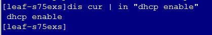
5. Enable DHCP Snooping or DHCP Replay debugging on the leaf device. Verify that the device has properly processed the DHCP packets.
Turn on the DHCP Snooping debugging switches on the device:
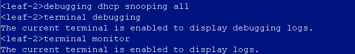
Users apply for addresses. In normal cases, the device will print the following DHCP packet interaction info:
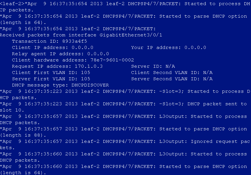
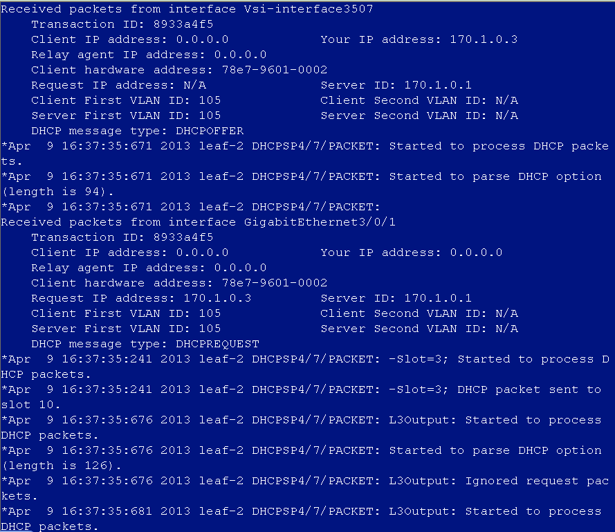
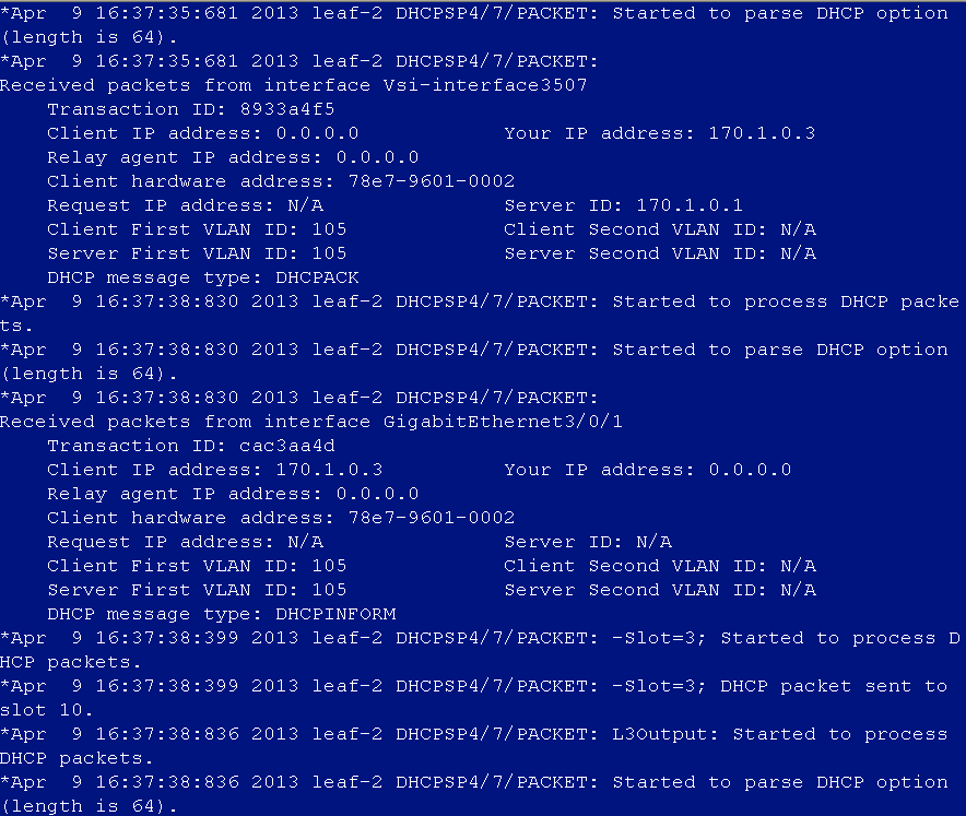
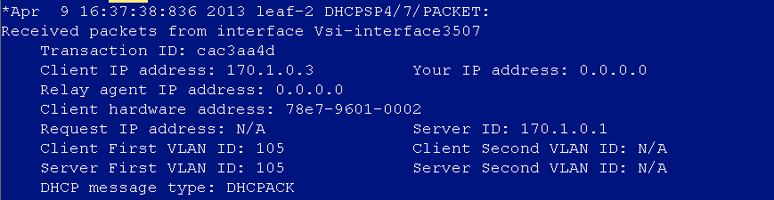
Turn on the DHCP Relay debugging switches on the device:
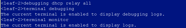
Users apply for addresses. In normal cases, the device will print the following DHCP packet interaction info:
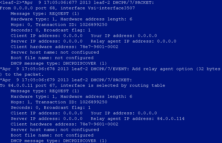
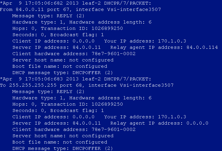
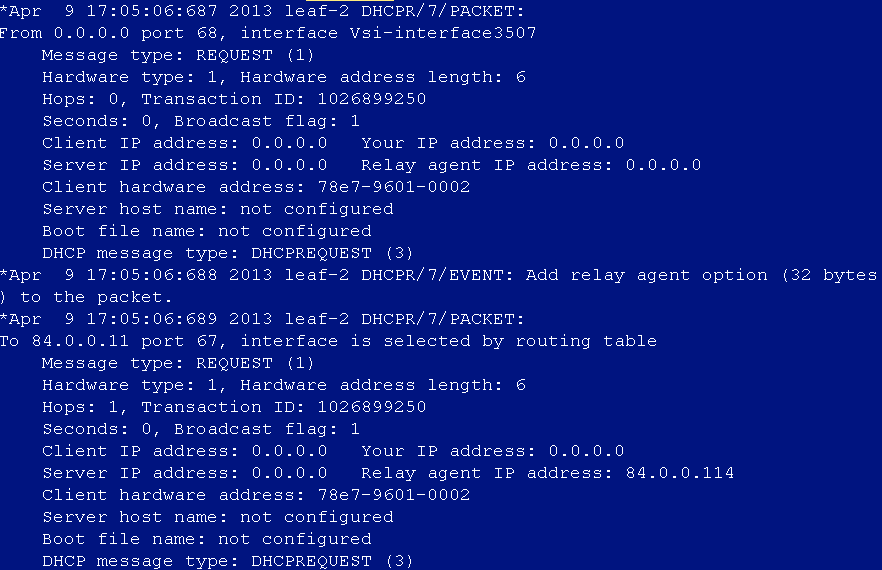
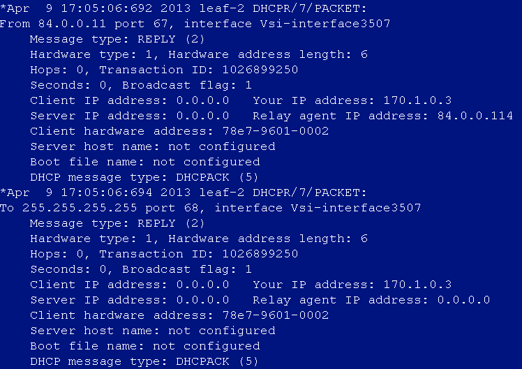
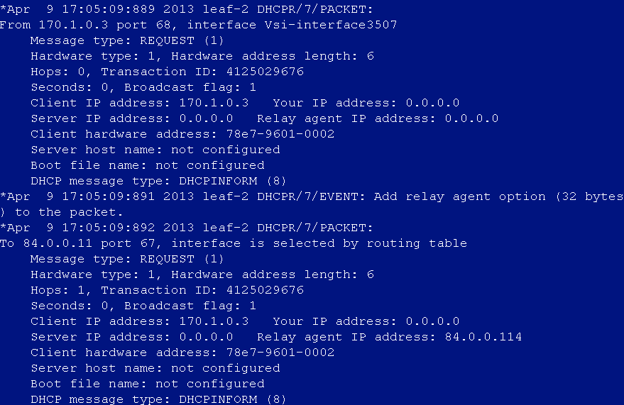
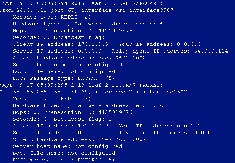
The debugging switches can be turned off by executing the following command or pressing Ctrl + O:
![]()
Primary/secondary leaf device switchover causes users offline (online check)
Issue
When a primary/secondary leaf device switchover occurs, some of the online users are logged off. Navigate to the Analysis > Access Analysis > Authentication Failure Log page to view the logs. The user offline reason is Online Check.
Cause
The default accounting interval of the AAA template is 15 minutes, and the default aging interval on the EIA is 30 minutes. When the primary and secondary devices are switched over, the accounting interval timer will be cleared. When there are a large number of online users, the accounting packets for some users will be delayed, resulting in iMC not receiving accounting updates within 30 minutes. Therefore, the users are logged off.
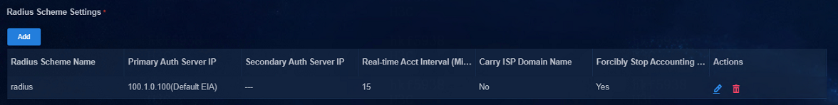
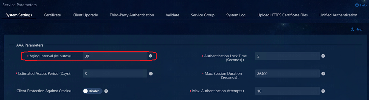
Solution
As a best practice, set the aging interval on the EIA to a larger value, preferably to 180 minutes.

User disconnection during a master node upgrade for Matrix
Issue
In a cluster, the PXC connection established by executing the service mha-mysql command traverses the haproxy LB component. The haproxy component distributes the connection load to three PXC instances. When Matrix is upgraded on a node, all pods on the node are placed in pending state. As a result, when the matrix2 node is upgraded, its pxc-node2 service is unavailable, and the connection distributed to this service is also unavailable. The online user list is not refreshed in real time, and the new UAM will detect user entries that ought to age out. After the entries age out, the user sessions are disconnected when user accounting packets are received.
Error log:
%% 2021-04-29 07:55:11.030 ; [ERR] ; [3380586240] ; DB ; ERR %D %N:%||Connection is not openning.
Solution
To avoid this issue, navigate to the Automation > User > Access Parameters > System Settings > System Parameters page, and set the aging interval to 180 minutes. The default value of this parameter will be set to 180 minutes in future versions of EIA.
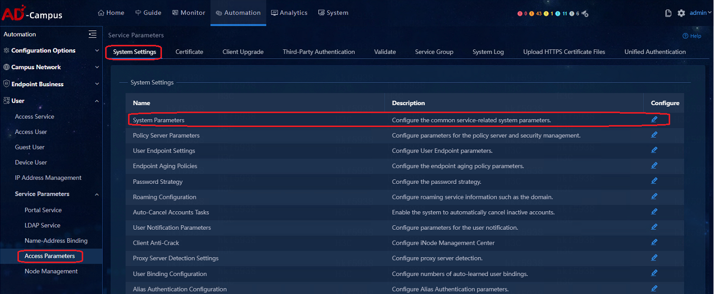
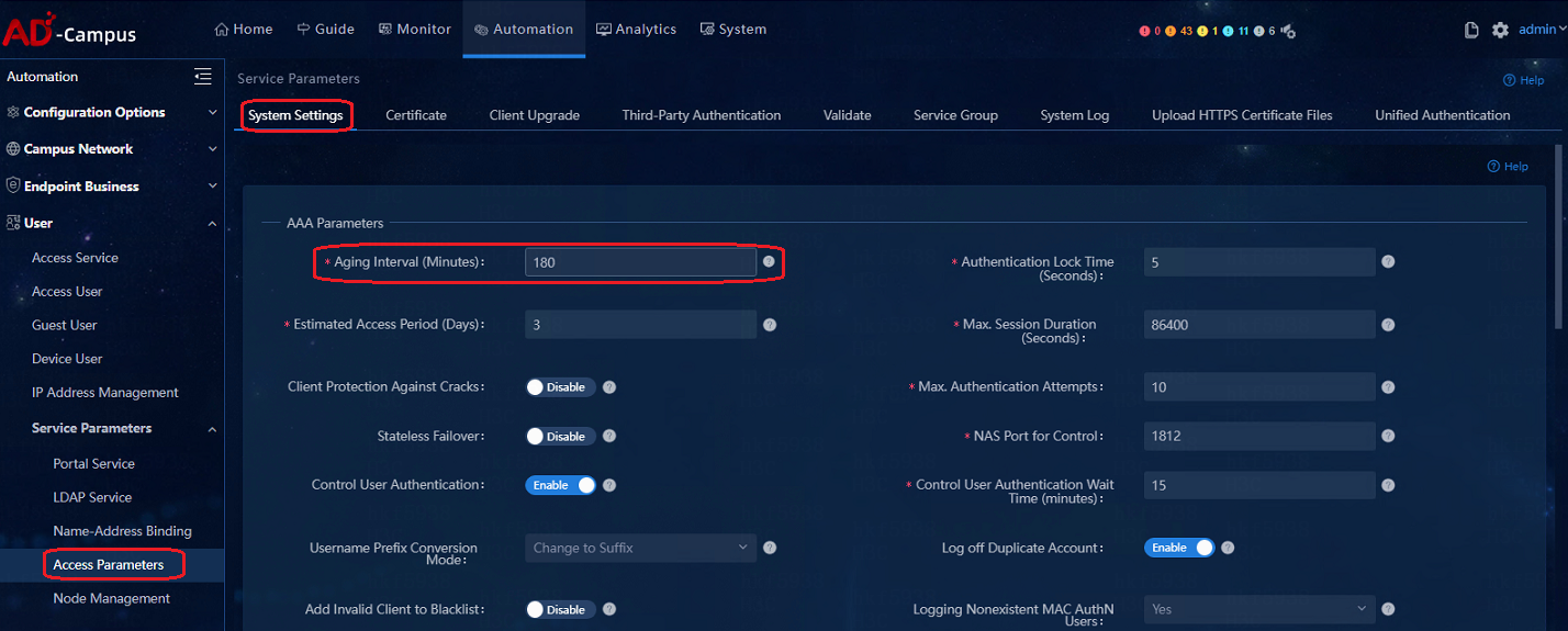
The DHCP server cannot be changed when users are online
You cannot change the DHCP server for an isolation domain if it has online users. If you change the DHCP server, online users might obtain new IP addresses when renewing their leases. The users can use the new IP addresses to access services. However, IP address conflicts might occur if the lease renew introduces Layer 2 network domain conflicts.
Downlink interface flapping on a leaf device interrupts services
Issue
This issue occurs if the following conditions exist:
· IP source guard and account-MAC binding are enabled.
· MAC authentication is configured.
· Downlink interfaces of a leaf device flap.
Cause
When downlink interfaces of a leaf device flap, users are disconnected, and the related DHCP snooping entries are also deleted.
When the downlink interfaces come up, user endpoints perform MAC authentication without user awareness, and the endpoints do not request IP addresses again. As a result, no DHCP snooping entries will be generated for the users. Without DHCP snooping entries, IP source guard cannot create IPSG entries for the users.
Solution
To resolve this issue, verify the following:
· Do not use account-MAC binding in conjunction with IPSG or ARP detection.
· Do not deploy IPSG configuration to leaf devices.
Wireless services
Switching between wireless AP modes
In the AD-Campus option, wireless services require the AC+Fit AP structure. When a wireless AP is initially deployed in fat AP mode, you must manually switch it to the fit AP mode before registration with the AC. The switching method is described in the documents for the wireless products.
|
|
NOTE: The dual uplink AP does not support automatic aggregation. |
Apply a routing policy to service VPNs when there are many wireless APs
When there are many wireless APs, the vpn-default instance will have many AP host routes, which will be imported to service VPNs, resulting in excessive routing entries on devices. Routing policy is required in all service VPNs of the spine and leaf devices to filter the host routes of these AP addresses.
|
|
NOTE: Routing policy is not required under vpn-default, but under service VPNs. |
The configuration is as follows:
Step1: Create an IP prefix list to match the prefix and host routes of the wireless Layer 2 domain.
ip prefix-list test index 50 permit 120.0.3.0 24 less-equal 32 (the segment and mask of the actual topology shall prevail)
Step2: Create routing policy to use the IP prefix list.
#
route-policy test deny node 10 //Deny the routes that matches the IP prefix list test.
if-match ip address prefix-list test
#
route-policy test permit node 20 //Permit unmatching routes
#
Step3: Apply the routing policy configured in Step 2 to each service VPN.
[Leaf_2-new-version-vpn-instance-XXXXX]dis th
#
ip vpn-instance XXXXX
route-distinguisher 1:2
description SDN_VRF_be123883-bb2e-4215-8c64-ebced0c1cbfe
import route-policy test
#
It takes longer time than expected for EIA to synchronize wireless user IP address changes
Issue
When IP addresses of wireless users change, such as switchover to the service IP addresses after MAC portal authentication, the users send accounting updates to EIA in 15 minutes instead of immediately. Therefore, EIA synchronizes its user list 15 minutes after the change occurs.
Cause
The AAA module of a wireless AC does not send accounting updates in real time after the IP address of an endpoint changes.
Solution
# Execute the following commands to enable immediate accounting updates upon endpoint IP changes in service template view.
client-security accounting-start trigger ipv4-ipv6
client-security accounting-update trigger ipv4-ipv6
The client-security accounting-update trigger ipv4-ipv6 command takes effect only when the client-security accounting-start trigger ipv4-ipv6 command takes effect.
The both the immediate and periodic accounting updates take effect.
If IPv6 wireless clients can trigger immediate accounting updates, and the periodic accounting update interval is 12 minutes, the device sends accounting updates every 12 minutes. When the IP addresses of IPv6 wireless clients change, the device immediately sends accounting updates.
If you enable immediate accounting updates with the service template enabled, immediate accounting updates take effect only on the clients that come online after your configuration.
EIA does not display IPv6 addresses of wireless users
Issue
ND snooping and DHCPv6 snooping are disabled by default in a service template.
Solution
# Enable ND snooping and DHCPv6 snooping in service template view.
client ipv6-snooping nd-learning enable
client ipv6-snooping dhcpv6-learning enable
ND snooping and DHCPv6 snooping enable APs to learn client IPv6 addresses through DHCPv6 and ND. The APs will create WLAN IP snooping entries based on the IPv6 addresses and MAC addresses of wireless clients and send the entries to ACs.
Automatic link aggregation is not supported by WTs
Issue
The links between a WT and a leaf device cannot be aggregated automatically.
Solution
Manually aggregate the links between a WT and a leaf device and configure the trunk type, PVID, and service instances on the aggregate interface.
DHCP server
H3C vDHCP server
Log in to vDHCP
Execute the docker command to go into the container:
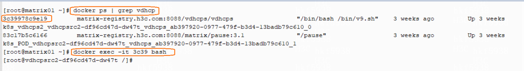
View the vDHCP address pool and address allocation
· View the startup.cfg file under the path of /mnt/flash:\/
In the startup.cfg file, the created address pool and the IP address binding info can be viewed. The startup.cfg file will synchronize the memory info every five minutes. Therefore, the viewed info may not be the latest.
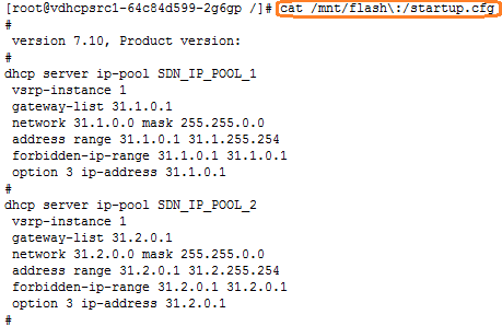
· Log in to the vDHCPShell to view
[root@vdhcpsrc1-64c84d599-2g6gp /]# vdhcpshell
The following commands are supported in the vDHCPShell:
display dhcp server ip-in-use
display dhcp server ip-in-use pool pool-name
display dhcp server ip-in-use ip ipv4-address
display ipv6 dhcp server ip-in-use
display ipv6 dhcp server ip-in-use pool pool-name
display ipv6 dhcp server ip-in-use address ipv6-address
[undo] debugging dhcp server {all | error | event | packet [verbose]}
[undo] debugging ipv6 dhcp server {all | error | event | packet [verbose]}
reset dhcp server ip-in-use
reset ipv6 dhcp server ip-in-use
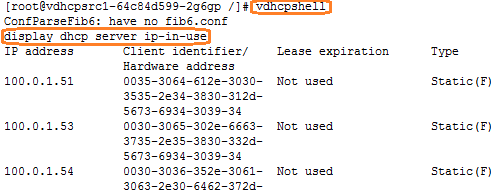
View the primary and secondary nodes of vDHCP
Log in to the vSRPLShell to view the primary and secondary nodes of the vDHCP and the node information.
The following commands are supported in the vSRPLShell:
display vsrp peer
display vsrp instance
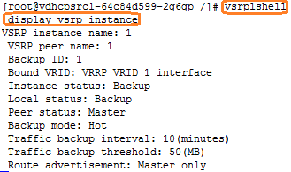
vDHCP primary and secondary IP address pools not synchronized
The primary and secondary servers of the vDHCP can only synchronize the assigned IP addresses and IP binding info, but not IP address pools. When the security groups are created, the controller needs to issue IP address pools to the primary and secondary servers respectively.
Assume that the primary or secondary vDHCP server node fails, and a new IP address pool is created on the controller. When the faulty vDHCP node recovers, the primary and secondary vDHCP servers will not synchronize the IP address pools. The controller provides a redeploy button on the DHCP Pools page. When the controller audits that the configuration on a vDHCP node is different from that issued by the controller, you can click the redeploy icon to redeploy the configuration to the node.
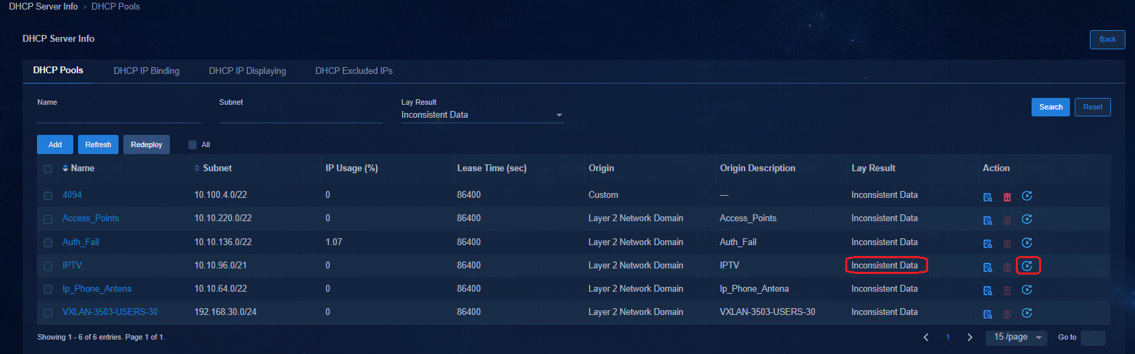
A vDHCP server can be managed by one system.
vDHCP supports only the HA mode in a cluster environment
vDHCP supports only the HA mode when it is incorporated by a controller in a cluster environment.
Microsoft DHCP server
The clock difference between Microsoft DHCP HA servers should not exceed 1 minute
The clock difference between Microsoft DHCP HA servers should not exceed 1 minute, or it will lead to abnormal HA status.
As a best practice, use NTP time synchronization.
The vlan4094 IP address pool is required on Microsoft DHCP server
The vlan4094 IP address pool is required on Microsoft DHCP server, or the DHCP request sent by the leaf device will not be responded.
Due to the features of the Microsoft DHCP server, you must create an IP address pool with the same network segment as the VSI4094 IP address. The IP address pool is not used for practical services, but only used to ensure that the Microsoft DHCP server can respond to the DHCP requests properly.
Add the IP address pool with the address range the same as the network segment of VSI4094. The gateway address uses the IP address of VLAN4094 interface on the Layer 3 switch, and other parameters can use the default values.
When multiple isolation domains share the same Microsoft DHCP server, multiple 4094 IP pools are required, each pool corresponding to one isolation domain's 4094 network segment. The following picture is only for demonstration.
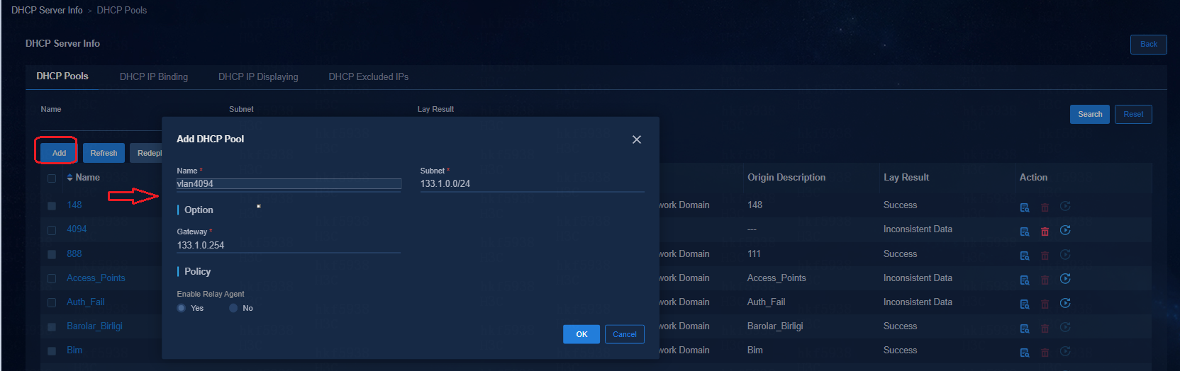
When the administrator password is changed on the Microsoft DHCP server, the password to the DHCP plugin must be changed synchronously
When the administrator password is changed on the Microsoft DHCP server, the passwords to the DHCP Plug Start service and DHCP Plug service of the DHCP plugin must be changed synchronously. The two services must be restarted after the passwords are changed.
In the DHCP HA scenario, the passwords on the two DHCP servers must be changed, and the passwords for the DHCP Plug Start and DHCP Plug services on the two servers must be changed accordingly.
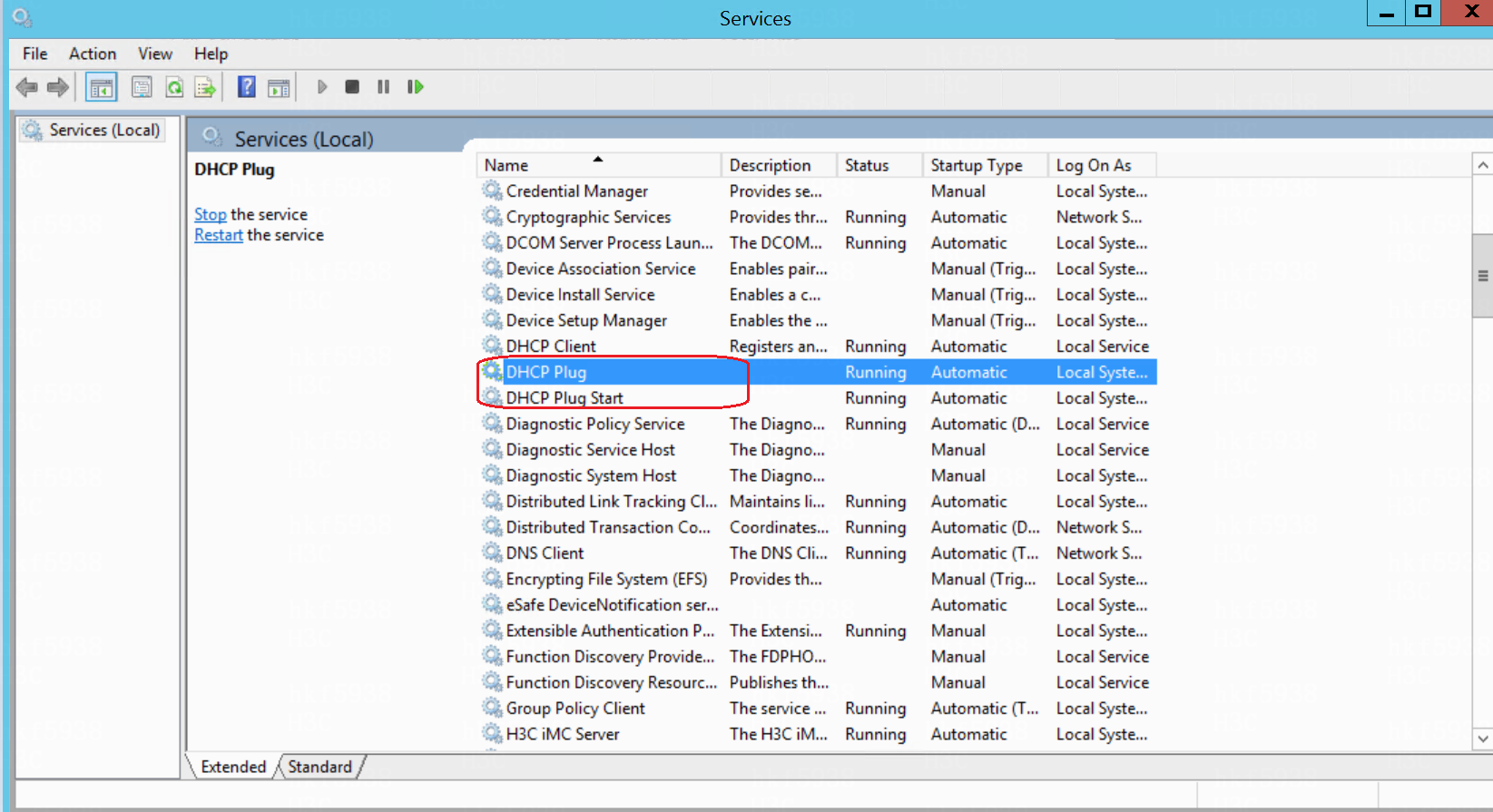
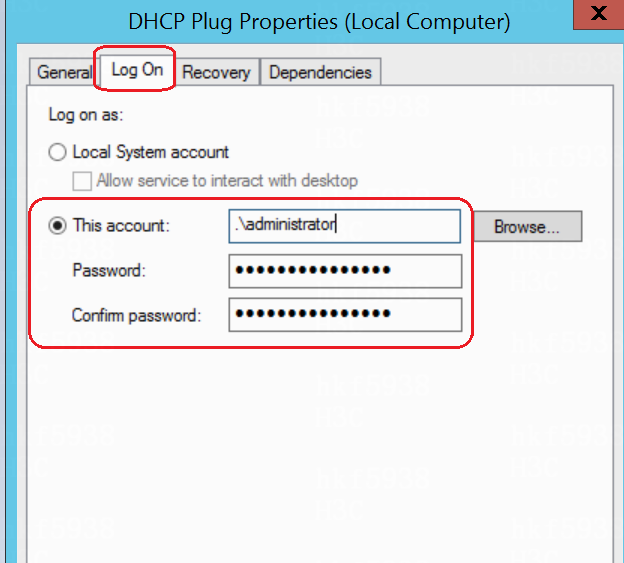
In the public host scenario, the authentication must be conducted on iNode client, and the MAC Portal authentication is not allowed
In a public host scenario, different accounts log in from the same endpoint, for example the endpoint for different doctors in the hospital or the public endpoint in the bank. In a public host scenario, the authentication must be conducted on iNode client, and the MAC Portal authentication is not allowed.
The Microsoft DHCP server supports IPv4/IPv6 dual stack
The Microsoft DHCP server supports IPv4/IPv6 dual stack. For IPv6 services, Microsoft DHCP server does not support IPv6 IP address binding.
The Microsoft DHCP server cannot be shared in the multiple isolation domains + name-address binding scenario
As a best practice, deploy a separate service DHCP server in each isolation domain in multi-isolation domain scenarios.
To use Microsoft DHCP servers in "multiple isolation domains + name-address binding" scenarios, each isolation domain must be deployed with one independent Microsoft DHCP server. Otherwise, the IP address allocation might be abnormal. (In principal, if one vDHCP server is adopted, each isolation domain can share this DHCP server.)
The number of user IP address bindings in a single address pool of the Microsoft DHCP server must be less than 2000
The number of user IP address bindings in a single address pool of the Microsoft DHCP server must be less than 2000
DHCP Server failover relationships will not be deleted when DHCP Server incorporation is removed on the controller
The ADCampus environment incorporates a Microsoft DHCP HA environment. When DHCP Server incorporation is removed on the controller, DHCP Server failover relationships will not be deleted. If the DHCP Server is incorporated by another controller, you must manually delete the failover relationships on the DHCP Server.
Only the primary DHCP server can create account-name bindings in a Microsoft DHCP HA environment
In a Microsoft DHCP HA environment, only the primary DHCP Server can create account-name bindings after the secondary DHCP Server fails. The account-name bindings will be automatically sent to the secondary DHCP Server by the plugin in 24 hours.
Ports required to be opened if firewalls exist
DHCP Server
|
Port |
Protocol |
Name |
Process |
Description |
|
67 |
UDP |
Broadcasting requests |
DHCP |
Clients broadcast requests to port 68 (bootps) |
|
68 |
UDP |
Broadcasting responses |
DHCP |
Clients broadcast response to port 67 (bootps) |
Internal ports
|
Port |
Protocol |
Name |
Process |
Description |
|
135 |
TCP |
RPC service |
RPC |
RPC service. |
|
647 |
TCP |
DHCP failover |
DHCP |
Dynamic host configuration protocol. |
DHCP Plugin
|
Port |
Protocol |
Name |
Process |
Description |
|
8958 |
TCP |
DHCP plugin |
dhcp-plug.exe |
P2P communication. |
SeerAnalyzer
It is forbidden to deploy GRPC configurations through the controller
Currently, the campus controller does not support the automated deployment of the GRPC related configurations. It is also forbidden to deploy GRPC related configurations in customized policies through the controller.
SeerAnalyzer restrictions of the S5560X and S6520X series devices
The performance of the 5560X/6520X series devices cannot meet the requirement of GRPC related configurations. Do not enable the GRPC related configurations on these devices when they are acting as the leaf devices. Do not configure the problem center monitoring analysis task and the problem center monitoring task in the SeerAnalyzer network analysis tasks.
Add labels for pods after upgrading a Unified Platform version earlier than E0607 with a SeerAnalzyer installed
Upgrading a Unified Platform version earlier than E0607 with a SeerAnalzyer installed causes all pods of the SeerAnalyzer to be in pending state. To resolve this issue, you must manually add labels for pods after the upgrade.
cd /opt/matrix/app/install/metadata/SA/scripts/
sh -x addLabelNodes.sh
Oasis is optional in the WSM component deployment and is required in the SeerAnalyzer component deployment
If only SeerAnalyzer is needed, deploy Oasis and SeerAnalyzer at the same time in System > Deployment in the Unified Platform.
If only WSM is needed, deploy Oasis and WSM in turn in Deploy > Applications in the Installer.
If both WSM and SeerAnalyzer are needed, deploy Oasis and SeerAnalyzer in System > Deployment in the Unified Platform, and then deploy WSM in the Installer. There is no need to deploy Oasis.
ARP flood optimization
To prevent ARP floods from overloading the CPUs of leaf devices, perform the optimization tasks in this chapter.
Disable devices from sending ARP and MLD packets received from VXLAN tunnels to CPUs
This task disables leaf devices to send the ARP and MLD packets received from remote leaf devices to CPUs in an EVPN VXLAN network with distributed gateways deployed. The ARP and MLD packets will be forwarded by hardware.
The related commands will be automatically deployed by the controller in future versions.
Procedure:
1. Upgrade the leaf devices to the most recent version.
2. Execute the undo mac-address static source-check enable command in system view.
3. If the flooding disable all all-direction or flooding disable broadcast all-direction setting already exists in VSI view, delete it by using the undo flooding disable command, and then execute the flooding disable all or flooding disable broadcast command.
4. Execute the forwarding vxlan-packet inner-protocol { ipv4 | ipv6 } command in system view based on the IP version used.
5. Assign all leaf downlink interfaces to isolation groups. If the leaf downlink interfaces forward inter-VLAN traffic, you can skip this step. However, broadcast, unknown multicast, and unknown unicast traffic will not be isolated between the leaf downlink interfaces.
Enable ARP source suppression
Execute the arp source-suppression enable and arp source-suppression limit commands based on the network traffic size.
Use this command if attack packets are sourced from a fixed IP address and destined for unresolvable destination IP addresses.
If unresolvable packets received from an IP address within 5 seconds exceed the limit, the device stops processing the packets from that IP address until the 5 seconds elapse.
Enable ARP packet rate limiting for specific source MAC addresses
Execute the arp source-mac filter/monitor and arp source-mac threshold threshold-value commands based on the network traffic size.
Use this command if attack ARP packets sourced from a fixed MAC address.
ARP packet rate limiting checks the number of ARP packets delivered to the CPU. If the number of packets from the same MAC address within 5 seconds exceeds a threshold, the device generates an ARP attack entry for the MAC address. Before the entry ages out, the device handles the attack by using either of the following methods:
· Monitor—Only generates log messages. This method can identify the attack source endpoints.
· Filter—Generates log messages and filters out subsequent ARP packets from the MAC address. This method might cause traffic interruption. Make sure you are fully aware of its impact when you use it.
Disable gratuitous ARP learning
Execute the undo gratuitous-arp-learning enable command in system view on access devices.
This command will be automatically deployed by the controller in future versions.
Use this command if endpoints send a large number of gratuitous ARP packets.
This command reduces the ARP entries learned in VLAN 1 and VLAN 4094.
Shut down the VLAN interface of VLAN 1 on access devices
Execute the shutdown VLAN 1 command on access devices.
This command will be automatically deployed by the controller in future versions.
Use this command after access devices are automatically deployed to prevent them from flooding ARP packets in VLAN 1 upon network flapping and downgrading the ARP processing capability of spine and leaf service gateways.
Configure broadcast and unknown unicast suppression
Execute the following commands based on the network traffic size:
· broadcast-suppression pps
· unicast-suppression pps
Enable ARP packet rate limiting
Execute the arp rate-limit command based on the network traffic size.
The ARP packet rate limit feature allows you to limit the rate of ARP packets delivered to the CPU. When the receiving rate of ARP packets on an interface exceeds the rate limit, those packets are discarded.
