- Released At: 28-06-2020
- Page Views:
- Downloads:
- Related Documents
-
|
|
|
H3C BRAS Campus Network |
|
Configuration Examples |
|
|
|
|
Software version: Release 7951P01
Document version: 6W100-20200625
Copyright © 2020 New H3C Technologies Co., Ltd. All rights reserved.
No part of this manual may be reproduced or transmitted in any form or by any means without prior written consent of New H3C Technologies Co., Ltd.
Except for the trademarks of New H3C Technologies Co., Ltd., any trademarks that may be mentioned in this document are the property of their respective owners.
The information in this document is subject to change without notice.
Contents
General restrictions and guidelines
Example: Configuring access-in and access-out separation in a BRAS campus network
Configuring IP addresses and routes
Example: Configuring IPoE common MAC authentication for dual-stack users
Configuring IP addresses and routes
Example: Configuring IPoE transparent MAC authentication for dual-stack users
Configuring IP addresses and routes
Example: Configuring multiple egress VPNs and ITA in a BRAS campus network (inline)
Example: Configuring multiple egress VPNs and ITA in a BRAS campus network (hairpin)
Example: Configuring multiple egress user groups in a BRAS campus network (remote authorization)
Configuring the RADIUS server and portal server (applicable to only remote AAA authentication)
Configuring IP addresses and routes
Configuring Router B (NAT device)
Example: Configuring multi egress user groups in a BRAS campus network (local authorization)
Configuring the RADIUS server and portal server (applicable to only remote AAA authentication)
Configuring IP addresses and routes
Example: Configuring ITA in a BRAS campus network
Configuring the RADIUS server and portal server
Configuring IP addresses and routes
Example: Configuring IPv6 direct portal authentication
Configuring the RADIUS server and portal server
Configuring IPv4/IPv6 addresses and routes
Introduction
The following information provides Broadband Remote Access Server (BRAS) configuration examples in campus network applications.
Prerequisites
The configuration examples were created and verified in a lab environment, and all the devices were started with the factory default configuration. When you are working on a live network, make sure you understand the potential impact of every command on your network.
The following information is provided based on the assumption that you have basic knowledge of PPPoE, IPoE, portal, QoS, VLAN termination, and QinQ.
General restrictions and guidelines
Only SPEX/CSPEX (except CSPEX-1104-E)/CEPC cards support PPPoE, IPoE, and portal.
Only SPEX/CSPEX (except CSPEX-1104-E)/CEPC cards support ITA, and ITA takes effect only on PPPoE, IPoE, and portal users. For different types of users, the number of traffic accounting levels is different, as shown in Table 1.
Table 1 Number of traffic accounting levels
|
ITA users |
Number of traffic accounting levels that can be configured |
|
|
SPEX-1204 cards |
CSPEX (except CSPEX-1104-E) and CEPC cards |
|
|
Portal users accessing through a VLAN interface |
7 |
7 |
|
· Portal users accessing through a Layer 3 Ethernet interface/subinterface or Layer 3 aggregate interface/subinterface · IPoE users · PPPoE users |
1 (only level 1 is supported in the current software version) |
4 (only levels 1 through 4 are supported in the current software version) |
The subinterface on an H3C BRAS can terminate VLANs 1 to 4094. To ensure proper BRAS operation, make sure the VLAN ID in a packet sent from a downstream device to a BRAS subinterface is in the range of 1 to 4094 when planning the network.
Example: Configuring access-in and access-out separation in a BRAS campus network
Network configuration
As shown in Figure 1, the dormitory area and office area of a campus network are directly attached to BRAS A. BRAS A acts as the access-in BRAS for users in the dormitory area and office area to access the campus network. BRAS B acts as the access-out BRAS for users in the campus network to access the Internet. Configure the BRAS campus network to meet the following requirements:
· Users in both the dormitory area and office area use PPPoE authentication and use the dialup client in the operating systems.
· A user cannot access the campus network or Internet before performing a PPPoE dialup.
· After a user passes PPPoE dialup authentication, the user can access only the internal network with the rate limit of 50 Mbps. Accounting is not performed for the user accessing the internal network.
· To access the Internet, a user must perform authentication again on BRAS B. After passing authentication, the user can access the Internet. The authentication process is transparent for the user. The school provides three monthly Internet access plans, with the speeds of 20 Mbps, 50 Mbps, and 100 Mbps separately. In this example, suppose users A, B, and C select the 20 Mbps, 50 Mbps, and 100 Mbps plans, respectively.

Analysis
· Because BRAS A has performed VLAN termination on users, BRAS B cannot identify users based on VLANs. Therefore, the QoS policy for Internet access must be deployed on BRAS A. Additionally, apply a QoS policy to the access interface on BRAS A to control the access speeds of users.
· For users to be transparently authenticated on BRAS B when accessing the Internet, configure IPoE authentication on BRAS B to use user IP addresses as usernames to initiate authentication on the RADIUS server. The RADIUS server automatically associates the second authentication with the first authentication to implement transparent second authentication.
· After IPoE access-out authentication is enabled on BRAS B, the attributes that IPoE reports to the RADIUS server carry the newly added private RADIUS attributes. After the RADIUS server receives user authentication requests with the private attribute, the RADIUS server parses the IP address in the username, and looks up the IP address in the access-in authentication data. If the IP address is found, the user is valid and allowed to access the Internet. Otherwise, the user is not allowed to access the Internet. For the RADIUS server, an IPoE user initiating unclassified-IP authentication must be a PPPoE user that has passed authentication on BRAS A. Therefore, you do not need to configure the username and password information for IPoE users on the RADIUS server.
· To prevent BRAS B from maintaining sessions of idle users, which wastes resources, configure the idle-cut feature to automatically log out idle users.
· To distinguish the internal network traffic and Internet traffic, you can use an ACL (ACL 3000 in this example) to match the specific internal network traffic, and then use an ACL (ACL 3001 in this example) to match traffic except internal traffic (the Internet traffic by default).
· When a PPPoE access user goes offline, the DHCP relay agent needs to look up the relay user address entry of the user. If the entry exists, the DHCP relay agent sends Release packets to the DHCP server to notify the DHCP server to release the user's address lease. For this purpose, execute the dhcp relay client-information record command to enable recording client information in relay entries.
Restrictions and guidelines
· As a best practice, use the H3C IMC server as the RADIUS server to cooperate with BRAS B to implement IPoE access-out authentication.
· If authorization attributes (for example, address pool) are configured both on the RADIUS server and in an ISP domain, the attributes configured on the RADIUS server apply. If the idle-cut attribute is configured both on the RADIUS server and in an ISP domain, the configuration in the ISP domain on the BRAS applies. In this example, all the authorization attributes have been configured in ISP domains. In a live network, configure the RADIUS server to authorize attributes or configure attributes in ISP domains as needed.
· Configure the usernames to carry ISP domain names on the IMC authentication server. If PPPoE access users and IPoE access users use different ISP domains, you must select both the PPPoE access ISP domain and IPoE access ISP domain for users on the IMC authentication server.
· In this example, both PPPoE users and IPoE users use ISP domain isp1.
· On the system parameters page in IMC, you must select Disable for Log off Duplicate Account.
· Set the Max. Concurrent Logins parameter to be no smaller than 2.
Procedures
Configuring the RADIUS server
# Configure PPPoE access users on IMC. (Details not shown.)
Configuring IP addresses and routes
As shown in Figure 1, configure IP addresses for interfaces, and make sure the BRASs and servers can reach each other at Layer 3. (Details not shown.)
Configuring the DHCP server
# Enable DHCP.
<DHCP> system-view
[DHCP] dhcp enable
# Create DHCP address pool pool1, which is to be used by users passing PPPoE dialup authentication.
[DHCP] dhcp server ip-pool pool1
# Specify primary subnet 3.3.0.0/16 for dynamic allocation in the address pool. Specify gateway address 3.3.3.1 and DNS server address 8.8.8.8 in the address pool.
[DHCP-dhcp-pool-pool1] network 3.3.0.0 16
[DHCP-dhcp-pool-pool1] gateway-list 3.3.3.1
[DHCP-dhcp-pool-pool1] dns-list 8.8.8.8
# Exclude IP address 3.3.3.1 from dynamic allocation.
[DHCP-dhcp-pool-pool1] forbidden-ip 3.3.3.1
[DHCP-dhcp-pool-pool1] quit
# Configure the default route to the PPPoE server (BRAS A).
[DHCP] ip route-static 0.0.0.0 0 4.4.4.1
Configuring access-in BRAS A
Configuring a user group
# Create user group g1.
<BRASA> system-view
[BRASA] user-group g1
New user group added.
[BRASA-ugroup-web] quit
Configuring a QoS policy to rate-limit the traffic to 50 Mbps but not perform accounting for internal network access traffic
This example uses user network segment 3.3.0.0/16 and server network segment 4.4.4.0/24 as the internal network segment.
# Configure ACL 3000.
[BRASA] acl advanced 3000
# Configure rules to match traffic between users and servers after users pass PPPoE dialup authentication.
[BRASA-acl-ipv4-adv-3000] rule 0 permit ip source 3.3.0.0 0.0.255.255 destination 4.4.4.0 0.0.0.255 user-group g1
[BRASA-acl-ipv4-adv-3000] rule 10 permit ip source 4.4.4.0 0.0.0.255 destination 3.3.0.0 0.0.255.255 user-group g1
# Configure a rule to match traffic between users after users pass PPPoE dialup authentication.
[BRASA-acl-ipv4-adv-3000] rule 20 permit ip source 3.3.0.0 0.0.255.255 destination 3.3.0.0 0.0.255.255 user-group g1
[BRASA-acl-ipv4-adv-3000] quit
|
|
NOTE: Because the default of an ACL rule is none (neither permit nor deny), traffic that does not match any rule is not processed. Therefore, do not add a rule to deny all traffic (for example, rule 30 deny ip) behind the last rule in ACL 3000. Otherwise, when the device executes QoS policy nei_waiwang_share, the class-behavior associations after the classifier 3000 behavior 3000 association cannot match any traffic. |
# Configure class 3000 to match packets matching ACL 3000 and from authenticated users.
[BRASA] traffic classifier 3000 operator and
[BRASA-classifier-3000] if-match acl 3000
[BRASA-classifier-3000] if-match authenticated-user
[BRASA-classifier-3000] quit
# Configure behavior 3000 to count traffic in bytes and rate-limit the traffic to 50000 kbps.
[BRASA] traffic behavior 3000
[BRASA-behavior-3000] accounting byte
[BRASA-behavior-3000] car cir 50000
[BRASA-behavior-3000] quit
# Create QoS policy nei_waiwang_share and associate class 3000 with behavior 3000.
[BRASA] qos policy nei_waiwang_share
[BRASA-qospolicy-nei_waiwang_share] classifier 3000 behavior 3000
[BRASA-qospolicy-nei_waiwang_share] quit
Configuring a QoS policy to rate-limit and perform accounting for Internet access traffic
# Configure ACL 3001.
[BRASA] acl advanced 3001
# Configure a rule to match all packets.
[BRASA-acl-ipv4-adv-3001] rule 30 permit ip user-group g1
[BRASA-acl-ipv4-adv-3001] quit
# Configure class cl_user1 to match packets carrying CVLAN 11, matching ACL 3001, and from authenticated users.
[BRASA] traffic classifier cl_user1 operator and
[BRASA-classifier-cl_user1] if-match customer-vlan-id 11
[BRASA-classifier-cl_user1] if-match acl 3001
[BRASA-classifier-cl_user1] if-match authenticated-user
[BRASA-classifier-cl_user1] quit
# Configure class cl_user2 to match packets carrying CVLAN 12, matching ACL 3001, and from authenticated users.
[BRASA] traffic classifier cl_user2 operator and
[BRASA-classifier-cl_user2] if-match customer-vlan-id 12
[BRASA-classifier-cl_user2] if-match acl 3001
[BRASA-classifier-cl_user2] if-match authenticated-user
[BRASA-classifier-cl_user2] quit
# Configure class cl_user3 to match packets carrying CVLAN 13, matching ACL 3001, and from authenticated users.
[BRASA] traffic classifier cl_user3 operator and
[BRASA-classifier-cl_user3] if-match customer-vlan-id 13
[BRASA-classifier-cl_user3] if-match acl 3001
[BRASA-classifier-cl_user3] if-match authenticated-user
[BRASA-classifier-cl_user3] quit
# Configure class cl_user4 to match packets carrying CVLAN 14, matching ACL 3001, and from authenticated users.
[BRASA] traffic classifier cl_user4 operator and
[BRASA-classifier-cl_user4] if-match customer-vlan-id 14
[BRASA-classifier-cl_user4] if-match acl 3001
[BRASA-classifier-cl_user4] if-match authenticated-user
[BRASA-classifier-cl_user4] quit
# Configure behavior be_20M to count traffic in bytes and rate-limit the traffic to 20000 kbps.
[BRASA] traffic behavior be_20M
[BRASA-behavior-be_20M] accounting byte
[BRASA-behavior-be_20M] car cir 20000
[BRASA-behavior-be_20M] quit
# Configure behavior be_50M to count traffic in bytes and rate-limit the traffic to 50000 kbps.
[BRASA] traffic behavior be_50M
[BRASA-behavior-be_50M] accounting byte
[BRASA-behavior-be_50M] car cir 50000
[BRASA-behavior-be_50M] quit
# Configure behavior be_100M to count traffic in bytes and rate-limit the traffic to 100000 kbps.
[BRASA] traffic behavior be_100M
[BRASA-behavior-be_100M] accounting byte
[BRASA-behavior-be_100M] car cir 100000
[BRASA-behavior-be_100M] quit
# Associate classes with behaviors in QoS policy nei_waiwang_share.
[BRASA] qos policy nei_waiwang_share
[BRASA-qospolicy-nei_waiwang_share] classifier cl_user1 behavior be_20M
[BRASA-qospolicy-nei_waiwang_share] classifier cl_user2 behavior be_50M
[BRASA-qospolicy-nei_waiwang_share] classifier cl_user3 behavior be_50M
[BRASA-qospolicy-nei_waiwang_share] classifier cl_user4 behavior be_100M
[BRASA-qospolicy-nei_waiwang_share] quit
Applying the QoS policy
# Enter the view of interface GigabitEthernet 3/1/1.1.
[BRASA] interface gigabitethernet 3/1/1.1
# Apply QoS policy nei_waiwang_share to the interface.
[BRASA–GigabitEthernet3/1/1.1] qos apply policy nei_waiwang_share inbound
[BRASA–GigabitEthernet3/1/1.1] qos apply policy nei_waiwang_share outbound
[BRASA–GigabitEthernet3/1/1.1] quit
Configuring a RADIUS scheme
# Create RADIUS scheme rs1, and enter its view.
[BRASA] radius scheme rs1
# Configure the primary authentication and accounting servers and the keys for secure RADIUS authentication and accounting communication for the RADIUS scheme.
[BRASA-radius-rs1] primary authentication 4.4.4.3
[BRASA-radius-rs1] primary accounting 4.4.4.3
[BRASA-radius-rs1] key authentication simple 123456
[BRASA-radius-rs1] key accounting simple 123456
# Enable accounting-on for RADIUS scheme rs1.
[BRASA-radius-rs1] accounting-on enable
[BRASA-radius-rs1] quit
# Specify the DAC as 4.4.4.3. Set the shared key to 123456 in plaintext form for secure communication between the DAS and DAC.
[BRASA] radius dynamic-author server
[BRASA-radius-da-server] client ip 4.4.4.3 key simple 123456
[BRASA-radius-da-server] quit
Configuring the DHCP relay agent
# Enable DHCP.
[BRASA] dhcp enable
# Enable recording client information in relay entries.
[BRASA] dhcp relay client-information record
# Enter the view of interface GigabitEthernet 3/1/1.1.
[BRASA] interface gigabitethernet 3/1/1.1
# Enable the DHCPv4 relay agent on the interface.
[BRASA–GigabitEthernet3/1/1.1] dhcp select relay proxy
[BRASA–GigabitEthernet3/1/1.1] quit
# Create DHCP relay address pool pool1, and specify gateway addresses and the DHCP server for the address pool.
[BRASA] dhcp server ip-pool pool1
[BRASA-dhcp-pool-pool1] gateway-list 3.3.3.1 export-route
[BRASA-dhcp-pool-pool1] remote-server 4.4.4.5
[BRASA-dhcp-pool-pool1] quit
Configuring an ISP domain
# Create ISP domain isp1, and enter its view.
[BRASA] domain name isp1
# Configure PPP users to use RADIUS scheme rs1 for authentication, authorization, and accounting.
[BRASA-isp-isp1] authentication ppp radius-scheme rs1
[BRASA-isp-isp1] authorization ppp radius-scheme rs1
[BRASA-isp-isp1] accounting ppp radius-scheme rs1
# Specify IPv4 address pool pool1 as the authorization IPv4 address pool and user group g1 as the authorization user group for users in ISP domain isp1.
[BRASA-isp-isp1] authorization-attribute ip-pool pool1
[BRASA-isp-isp1] authorization-attribute user-group g1
[BRASA-isp-isp1] quit
Configuring a Virtual-Template interface
# Create interface Virtual-Template 1, and enable PPP accounting and CHAP authentication on the interface.
[BRASA] interface virtual-template 1
[BRASA-Virtual-Template1] ppp account-statistics enable
[BRASA-Virtual-Template1] ppp authentication-mode chap domain isp1
[BRASA-Virtual-Template1] quit
Configuring VLAN termination
# Configure VLAN termination on GigabitEthernet 3/1/1.1, and bind the interface to Virtual-Template 1.
[BRASA] interface gigabitethernet 3/1/1.1
[BRASA-GigabitEthernet3/1/1.1] vlan-type dot1q vid 101 second-dot1q 11 to 14
[BRASA-GigabitEthernet3/1/1.1] pppoe-server bind virtual-template 1
Configuring access-out BRAS B
Configuring a RADIUS scheme
# Create RADIUS scheme rs1, and enter its view.
[BRASB] radius scheme rs1
# Configure the primary authentication and accounting servers and the keys for secure RADIUS authentication and accounting communication for the RADIUS scheme.
[BRASB-radius-rs1] primary authentication 4.4.4.3
[BRASB-radius-rs1] primary accounting 4.4.4.3
[BRASB-radius-rs1] key authentication simple 123456
[BRASB-radius-rs1] key accounting simple 123456
# Enable accounting-on for RADIUS scheme rs1.
[BRASB-radius-rs1] accounting-on enable
[BRASB-radius-rs1] quit
# Specify the DAC as 4.4.4.3. Set the shared key to 123456 in plaintext form for secure communication between the DAS and DAC.
[BRASB] radius dynamic-author server
[BRASB-radius-da-server] client ip 4.4.4.3 key simple 123456
[BRASB-radius-da-server] quit
Configuring the authentication domain for IPoE
# Create ISP domain isp1, and enter its view.
[BRASB] domain name isp1
# Configure IPoE users to use RADIUS scheme rs1 for authentication, authorization, and accounting in the ISP domain.
[BRASB-isp-isp1] authentication ipoe radius-scheme rs1
[BRASB-isp-isp1] authorization ipoe radius-scheme rs1
[BRASB-isp-isp1] accounting ipoe radius-scheme rs1
# Specify an idle timeout period of 30 minutes in the ISP domain. The traffic size generated within the idle time period is 10240 bytes.
[BRASB-isp-isp1] authorization-attribute idle-cut 30 10240
[BRASB-isp-isp1] quit
Configuring IPoE authentication
# Enter the view of interface GigabitEthernet 3/1/1.
[BRASB] interface gigabitethernet 3/1/1
# Enable IPoE and configure the Layer 3 access mode.
[BRASB–GigabitEthernet3/1/1] ip address 5.5.5.2 24
[BRASB–GigabitEthernet3/1/1] ip subscriber routed enable
# Enable unclassified-IP packet initiation.
[BRASB–GigabitEthernet3/1/1] ip subscriber initiator unclassified-ip enable
# Configure ISP domain isp1 for IPv4 unclassified-IP users.
[BRASB–GigabitEthernet3/1/1] ip subscriber unclassified-ip domain isp1
# Enable IPoE access-out authentication for IPv4 users.
[BRASB–GigabitEthernet3/1/1] ip subscriber access-out
[BRASB-GigabitEthernet3/1/1] quit
Configuring Switch A
# Create SVLAN 101.
<SwitchA> system-view
[SwitchA] vlan 101
[SwitchA-vlan101] quit
# Configure GigabitEthernet 3/0/1 as a hybrid port and assign it to SVLAN 101 as a tagged member.
[SwitchA] interface gigabitethernet 3/0/1
[SwitchA-GigabitEthernet3/0/1] port link-type hybrid
[SwitchA-GigabitEthernet3/0/1] port hybrid vlan 101 tagged
[SwitchA-GigabitEthernet3/0/1] quit
# Configure GigabitEthernet 3/0/2 and GigabitEthernet 3/0/3 as trunk ports and assign them to SVLAN 101.
[SwitchA] interface range gigabitethernet 3/0/2 to gigabitethernet 3/0/3
[SwitchA-if-range] port link-type trunk
[SwitchA-if-range] port trunk permit vlan 101
# Configure SVLAN 101 as the PVID for GigabitEthernet 3/0/2 and GigabitEthernet 3/0/3 and enable QinQ on them.
[SwitchA-if-range] port trunk pvid vlan 101
[SwitchA-if-range] qinq enable
[SwitchA-if-range] quit
Configuring Switch B
# Create VLANs 11 and 12.
[SwitchB] vlan 11 to 12
# Configure GigabitEthernet 3/0/1 as a trunk port and assign it to VLANs 11 and 12.
[SwitchB] interface gigabitethernet 3/0/1
[SwitchB-GigabitEthernet3/0/1] port link-type trunk
[SwitchB-GigabitEthernet3/0/1] port trunk permit vlan 11 12
[SwitchB-GigabitEthernet3/0/1] quit
# Assign GigabitEthernet 3/0/2 to VLAN 11.
[SwitchB] interface gigabitethernet 3/0/2
[SwitchB-GigabitEthernet3/0/2] port access vlan 11
[SwitchB-GigabitEthernet3/0/2] quit
# Assign GigabitEthernet 3/0/3 to VLAN 12.
[SwitchB] interface gigabitethernet 3/0/3
[SwitchB-GigabitEthernet3/0/3] port access vlan 12
[SwitchB-GigabitEthernet3/0/3] quit
Configuring Switch C
# Create VLANs 13 and 14.
[SwitchC] vlan 13 to 14
# Configure GigabitEthernet 3/0/1 as a trunk port and assign it to VLANs 13 and 14.
[SwitchC] interface gigabitethernet 3/0/1
[SwitchC-GigabitEthernet3/0/1] port link-type trunk
[SwitchC-GigabitEthernet3/0/1] port trunk permit vlan 13 14
[SwitchC-GigabitEthernet3/0/1] quit
# Assign GigabitEthernet 3/0/2 to VLAN 13.
[SwitchC] interface gigabitethernet 3/0/2
[SwitchC-GigabitEthernet3/0/2] port access vlan 13
[SwitchC-GigabitEthernet3/0/2] quit
# Assign GigabitEthernet 3/0/3 to VLAN 14.
[SwitchC] interface gigabitethernet 3/0/3
[SwitchC-GigabitEthernet3/0/3] port access vlan 14
[SwitchC-GigabitEthernet3/0/3] quit
Verifying the configuration
# Use Host A as an example. Install the PPPoE client software on the host, and use username User1@isp1 and password pass1 to dial to BRAS A.
# Execute the display dhcp relay client-information command to view the relay entries on the relay agent.
[BRASA] display dhcp relay client-information
Total number of client-information items: 1
Total number of dynamic items: 1
Total number of temporary items: 0
IP address MAC address Type Interface VPN name
3.3.3.2 e839-3563-fb21 Dynamic BAS0 N/A
The output shows that Host A has obtained an IP address.
# View detailed information about user User1@isp1.
[BRASA] display ppp access-user username User1@isp1 verbose
Basic:
Interface: BAS0
PPP index: 0x140000105
User ID: 0x20000001
Username: User1@isp1 //Username used for PPPoE dialup
Domain: isp1 //ISP domain to which the dialup user belongs
Access interface: GE3/1/1.1 //Access interface of the dialup user
Service-VLAN/Customer-VLAN: 101/11 //SVLAN and CVLAN encapsulated in packets of the dialup user
VXLAN ID: -
MAC address: e839-3563-fb21 //Host MAC address of the dialup user
IP address: 3.3.3.2 //IP address assigned to the user by the DHCP server
Primary DNS server: 8.8.8.8
IPv6 address: -
IPv6 PD prefix: -
IPv6 ND prefix: -
User address type: N/A
VPN instance: -
Access type: PPPoE //Access type of the user
Authentication type: CHAP //Authentication type of the access user
PPPoE:
Session ID: 1
AAA:
Authentication state: Authenticated
Authorization state: Authorized
Realtime accounting switch: Open
Realtime accounting interval: 900s
Login time: 2014-11-6 8:31:31:725
Accounting start time: 2014-11-6 8:31:32:275
Online time(hh:mm:ss): 0:3:46
Accounting state: Accounting
Acct start-fail action: Online
Acct update-fail action: Online
Acct quota-out action: Offline
Dual-stack accounting mode: Merge
Idle cut: 0 sec 0 byte, direction: Both
Session timeout: -
Time remained: -
Traffic quota: -
Traffic remained: -
Redirect WebURL: -
ITA policy name: -
MRU: 1480 bytes
IPv4 MTU: 1480 bytes
IPv6 MTU: 1480 bytes
Subscriber ID: -
ACL&QoS:
User profile: -
Session group profile: -
User group acl: g1 (active)
Inbound CAR: -
Outbound CAR: -
User inbound priority: -
User outbound priority: -
Flow Statistic:
IPv4 uplink packets/bytes: 508/53292
IPv4 downlink packets/bytes: 285/26198
IPv6 uplink packets/bytes: 0/0
IPv6 downlink packets/bytes: 0/0
The output shows that Host A has successfully dialed to BRAS A and obtained IP address 3.3.3.2 dynamically.
# After the user passes authentication, execute the display ip subscriber session command on BRAS B to view the corresponding IPoE user information.
[BRASB] display ip subscriber session
Type: D-DHCP S-Static U-Unclassified-IP N-NDRS
Interface IP address MAC address Type State
IPv6 address SVLAN/CVLAN VXLAN
Username
GE3/1/1 3.3.3.2 e839-3563-fb21 U/- Online
- -/- -
3.3.3.2
The output shows that the user has passed IPoE access-out authentication on BRAS B.
Configuration files
· DHCP server:
#
dhcp enable
#
dhcp server ip-pool pool1
network 3.3.0.0 mask 255.255.0.0
dns-list 8.8.8.8
forbidden-ip 3.3.3.1
gateway-list 3.3.3.1
#
interface GigabitEthernet3/0/1
port link-mode route
ip address 4.4.4.5 255.255.255.0
#
ip route-static 0.0.0.0 0 4.4.4.1
#
· BRAS A:
#
dhcp enable
dhcp relay client-information record
#
traffic classifier 3000 operator and
if-match acl 3000
if-match authenticated-user
#
traffic classifier cl_user1 operator and
if-match customer-vlan-id 11
if-match acl 3001
if-match authenticated-user
#
traffic classifier cl_user2 operator and
if-match customer-vlan-id 12
if-match acl 3001
if-match authenticated-user
#
traffic classifier cl_user3 operator and
if-match customer-vlan-id 13
if-match acl 3001
if-match authenticated-user
#
traffic classifier cl_user4 operator and
if-match customer-vlan-id 14
if-match acl 3001
if-match authenticated-user
#
traffic behavior 3000
accounting byte
car cir 50000 cbs 3125000 ebs 0 green pass red discard yellow pass
#
traffic behavior be_100M
accounting byte
car cir 100000 cbs 6250000 ebs 0 green pass red discard yellow pass
#
traffic behavior be_20M
accounting byte
car cir 20000 cbs 1250000 ebs 0 green pass red discard yellow pass
#
traffic behavior be_50M
accounting byte
car cir 50000 cbs 3125000 ebs 0 green pass red discard yellow pass
#
qos policy nei_waiwang_share
classifier 3000 behavior 3000
classifier cl_user1 behavior be_20M
classifier cl_user2 behavior be_50M
classifier cl_user3 behavior be_50M
classifier cl_user4 behavior be_100M
#
dhcp server ip-pool pool1
gateway-list 3.3.3.1 export-route
remote-server 4.4.4.5
#
interface Virtual-Template1
ppp authentication-mode chap
ppp account-statistics enable
#
interface GigabitEthernet3/1/1
port link-mode route
#
interface GigabitEthernet3/1/1.1
qos apply policy nei_waiwang_share inbound
qos apply policy nei_waiwang_share outbound
vlan-type dot1q vid 101 second-dot1q 11 to 14
pppoe-server bind virtual-template 1
#
interface GigabitEthernet3/1/2
port link-mode route
ip address 5.5.5.1 255.255.255.0
#
interface GigabitEthernet3/1/3
port link-mode route
ip address 4.4.4.1 255.255.255.0
#
acl advanced 3000
rule 0 permit ip source 3.3.0.0 0.0.255.255 destination 4.4.4.0 0.0.0.255 user-group g1
rule 10 permit ip source 4.4.4.0 0.0.0.255 destination 3.3.0.0 0.0.255.255 user-group g1
rule 20 permit ip source 3.3.0.0 0.0.255.255 destination 3.3.0.0 0.0.255.255 user-group g1
#
acl advanced 3001
rule 30 permit ip user-group g1
#
radius scheme rs1
primary authentication 4.4.4.3
primary accounting 4.4.4.3
accounting-on enable
key authentication cipher $c$3$XqHhm+QZo4fEaQkP+ltqssWYq0o4hhJp/g==
key accounting cipher $c$3$ahutaD/6BL3qG0F5fyjBc8qI0vmptwNsmw==
#
radius dynamic-author server
client ip 4.4.4.3 key cipher $c$3$Td30doCnLkhF7bhiYp4bk9DU96+XBStLkA==
#
domain name isp1
authorization-attribute user-group g1
authorization-attribute ip-pool pool1
authentication ppp radius-scheme rs1
authorization ppp radius-scheme rs1
accounting ppp radius-scheme rs1
#
user-group g1
#
· BRAS B:
#
interface GigabitEthernet3/1/1
port link-mode route
ip address 5.5.5.2 255.255.255.0
ip subscriber routed enable
ip subscriber initiator unclassified-ip enable
ip subscriber unclassified-ip domain isp1
ip subscriber access-out
#
interface GigabitEthernet3/1/2
port link-mode route
ip address 6.6.6.1 255.255.255.0
#
interface GigabitEthernet3/1/3
port link-mode route
ip address 4.4.4.2 255.255.255.0
#
radius scheme rs1
primary authentication 4.4.4.3
primary accounting 4.4.4.3
accounting-on enable
key authentication cipher $c$3$DjpIVXm7T/Agf8WLNpF11mEYtx7lb2m51w==
key accounting cipher $c$3$4/FLMIce3DXgzHnY/oNl8SITZPze34E+cQ==
#
radius dynamic-author server
client ip 4.4.4.3 key cipher $c$3$Td30doCnLkhF7bhiYp4bk9DU96+XBStLkA==
#
domain name isp1
authorization-attribute idle-cut 30 10240
authentication ipoe radius-scheme rs1
authorization ipoe radius-scheme rs1
accounting ipoe radius-scheme rs1
#
· Switch A:
#
vlan 101
#
interface GigabitEthernet3/0/1
port link-mode bridge
port link-type hybrid
port hybrid vlan 101 tagged
port hybrid vlan 1 untagged
#
interface GigabitEthernet3/0/2
port link-mode bridge
port link-type trunk
port trunk permit vlan 101
port trunk pvid vlan 101
qinq enable
#
interface GigabitEthernet3/0/3
port link-mode bridge
port link-type trunk
port trunk permit vlan 101
port trunk pvid vlan 101
qinq enable
#
· Switch B:
#
vlan 11 to 12
#
interface GigabitEthernet3/0/1
port link-mode bridge
port link-type trunk
port trunk permit vlan 11 12
#
interface GigabitEthernet3/0/2
port link-mode bridge
port access vlan 11
#
interface GigabitEthernet3/0/3
port link-mode bridge
port access vlan 12
#
· Switch C:
#
vlan 13 to 14
#
interface GigabitEthernet3/0/1
port link-mode bridge
port link-type trunk
port trunk permit vlan 13 14
#
interface GigabitEthernet3/0/2
port link-mode bridge
port access vlan 13
#
interface GigabitEthernet3/0/3
port link-mode bridge
port access vlan 14
#
Example: Configuring IPoE common MAC authentication for dual-stack users
Network configuration
As shown in Figure 2:
· The host accesses the BRAS as a DHCP client though a Layer 2 device. It obtains configuration information from the DHCP server through the BRAS.
· The BRAS performs AAA for the host through the RADIUS server.
· A server installed with H3C IMC acts as the RADIUS server, portal authentication server, and the portal Web server.
· The FTP server is an internal network server.
· Limit the access rate to 5 Mbps for the user after passing Web authentication.

Analysis
To meet bandwidth requirements of users, this example authorizes user profiles for rate limiting.
To improve the forwarding efficiency, classify the traffic in the IPoE preauthentication domain into HTTP traffic, HTTPS traffic, and common IP packets and assign them to different queues. Configure three class-behavior associations to process the traffic to be sent to the CPU:
· Configure a class to match HTTP traffic from the user group created in the preauthentication domain, and associate the class with a behavior containing the redirect http-to-cpu action.
· Configure a class to match HTTPS traffic from the user group created in the preauthentication domain, and associate the class with a behavior containing the redirect https-to-cpu action.
· Configure a class to match IP traffic from the user group created in the preauthentication domain, and associate the class with a behavior containing the redirect cpu action.
When a BRAS access user goes offline, the DHCP relay agent needs to query the relay user address entry of the user. If the entry exists, the DHCP relay agent sends Release packets to the DHCP server to notify the DHCP server to release the user's address lease. For this purpose, execute the dhcp relay client-information record command to enable recording client information in relay entries.
Restrictions and guidelines
The DHCP server in this example is simulated by a device. As a best practice, use a dedicated DHCP server in actual applications.
By default, the HTTPS redirect listening port number is not configured. To configure the HTTPS port number, execute the http-redirect https-port command. Make sure the listening port number does not conflict with existing port numbers.
Procedures
Configuring IP addresses and routes
As shown in Figure 2, configure IP addresses for interfaces, and make sure the BRAS and servers can reach each other at Layer 3.
Configuring the DNS server
Configure the DNS server properly, so that the server can parse the IPv4 URL or IPv6 URL corresponding to the Web authentication page http://www.h3c.web.com according to the first protocol stack that comes online of the IPoE dual-stack user. (Details not shown.)
Configuring the DHCP server
Configuring a DHCPv4 address pool
# Enable DHCP.
<DHCP> system-view
[DHCP] dhcp enable
# Create a DHCPv4 address pool named pool1 and enter its view.
[DHCP] dhcp server ip-pool pool1
# Specify primary subnet 192.168.0.0/24 for dynamic allocation in address pool pool1.
[DHCP-dhcp-pool-pool1] network 192.168.0.0 24
# Specify gateway address 192.168.0.1 in address pool pool1.
[DHCP-dhcp-pool-pool1] gateway-list 192.168.0.1
# Exclude DHCP address 192.168.0.1 from dynamic allocation in address pool pool1.
[DHCP-dhcp-pool-pool1] forbidden-dhcp 192.168.0.1
[DHCP-dhcp-pool-pool1] quit
# Configure a static route to specify the next hop of DHCPv4 replies destined to network segment 192.168.0.0 as the IP address of the interface connected to the DHCPv4 client, 4.4.4.2.
[DHCP] ip route-static 192.168.0.0 24 4.4.4.2
Configuring a DHCPv6 address pool
# Create a DHCPv6 address pool named pool2 and enter its view.
[DHCP] ipv6 dhcp pool pool2
# Specify primary subnet 192::0/64 for dynamic allocation in address pool pool2.
[DHCP-dhcpv6-pool-pool2] network 192::0/64
[DHCP-dhcpv6-pool-pool2] quit
# Exclude IP address 192::1 from dynamic allocation in address pool pool2.
[DHCP] ipv6 dhcp server forbidden-address 192::1
# Enable the DHCPv6 server on GigabitEthernet 3/1/1.
[DHCP] interface gigabitethernet 3/1/1
[DHCP-GigabitEthernet3/1/1] ipv6 dhcp select server
[DHCP-GigabitEthernet3/1/1] quit
# Configure a static route to specify the next hop of DHCPv6 replies destined to network segment 192::0 as the IP address of the interface connected to the DHCPv6 client, 4::2.
[DHCP] ipv6 route-static 192::0 64 4::2
Configuring the BRAS
Configuring the DHCP relay agent
# Enable DHCP.
[BRAS] dhcp enable
# Enable recording client information in relay entries.
[BRAS] dhcp relay client-information record
# Disable the DHCP relay agent to periodically refresh dynamic relay entries.
[BRAS] undo dhcp relay client-information refresh enable
# Create a DHCP relay address pool named pool1.
[BRAS] dhcp server ip-pool pool1
# Specify the gateway address in address pool pool1.
[BRAS-dhcp-pool-pool1] gateway-list 192.168.0.1 24 export-route
# Specify DHCP server 4.4.4.3 in address pool pool1.
[BRAS-dhcp-pool-pool1] remote-server 4.4.4.3
[BRAS-dhcp-pool-pool1] quit
# Create a DHCP relay address pool named pool2.
[BRAS] ipv6 dhcp pool pool2
# Specify gateway address 192::1 in address pool pool2.
[BRAS-dhcpv6-pool-pool2] gateway-list 192::1
# Specify DHCP server 4::3 in DHCP relay address pool pool2.
[BRAS-dhcpv6-pool-pool2] remote-server 4::3
[BRAS-dhcpv6-pool-pool2] quit
# Enable the DHCPv4 relay agent on GigabitEthernet 3/1/2.
[BRAS] interface gigabitethernet 3/1/2
[BRAS–GigabitEthernet3/1/2] dhcp select relay proxy
# Automatically generate a link-local address for GigabitEthernet 3/1/2.
[BRAS–GigabitEthernet3/1/2] ipv6 address auto link-local
# Enable the DHCPv6 relay agent on GigabitEthernet 3/1/2.
[BRAS–GigabitEthernet3/1/2] ipv6 dhcp select relay
# Enable recording client information in DHCPv6 relay entries.
[BRAS–GigabitEthernet3/1/2] ipv6 dhcp relay client-information record
# Enable IPv6 release notification.
[BRAS–GigabitEthernet3/1/2] ipv6 dhcp relay release-agent
# Disable RA message suppression on GigabitEthernet 3/1/2.
[BRAS–GigabitEthernet3/1/2] undo ipv6 nd ra halt
# Set the managed address configuration flag (M) to 1 in RA advertisements to be sent. Then, the host uses a DHCPv6 server to obtain IPv6 addresses.
[BRAS–GigabitEthernet3/1/2] ipv6 nd autoconfig managed-address-flag
# Set the other stateful configuration flag (O) to 1 in RA advertisements to be sent. Then, the host uses a DHCPv6 server to obtain configuration information other than IPv6 addresses.
[BRAS–GigabitEthernet3/1/2] ipv6 nd autoconfig other-flag
# Disable GigabitEthernet 3/1/2 from advertising the specified prefix in RA messages, preventing the endpoint from obtaining a temporary IPv6 address. In an IPv6 network, an endpoint might use a temporary IPv6 address for IPoE Web authentication, which will cause authentication failure.
[BRAS–GigabitEthernet3/1/2] ipv6 nd ra prefix 192::/64 no-advertise
[BRAS–GigabitEthernet3/1/2] quit
Configuring the portal servers
# Configure the IP address of the IPv4 portal authentication server newpt1 as 4.4.4.5 and the plaintext key 123456.
[BRAS] portal server newpt1
[BRAS-portal-server-newpt1] ip 4.4.4.5 key simple 123456
[BRAS-portal-server-newpt1] quit
# Configure the IPv6 address of the IPv6 portal authentication server newpt2 as 4::5 and the plaintext key 123456.
[BRAS] portal server newpt2
[BRAS-portal-server-newpt2] ipv6 4::5 key simple 123456
[BRAS-portal-server-newpt2] quit
Specifying the HTTPS redirect listening port number
# Specify 11111 as the HTTPS redirect listening port number.
[BRAS] http-redirect https-port 11111
Creating a local user group
# Create a local user group named web.
[BRAS] user-group web
New user group added.
[BRAS-ugroup-web] quit
Configuring QoS
1. Configure ACLs for preauthentication:
# Create an IPv4 and IPv6 advanced ACL named web_permit separately. Configure a rule to permit all packets destined for the portal server from users in user group web.
[BRAS] acl advanced name web_permit
[BRAS-acl-ipv4-adv-web_permit] rule 0 permit ip destination 4.4.4.5 0 user-group web
[BRAS-acl-ipv4-adv-web_permit] quit
[BRAS] acl ipv6 advanced name web_permit
[BRAS-acl-ipv6-adv-web_permit] rule 0 permit ipv6 destination 4::5 128 user-group web
[BRAS-acl-ipv6-adv-web_permit] quit
# Create an IPv4 and IPv6 advanced ACL named neiwang separately. Configure a rule to permit all packets destined for the internal network server from users in user group web.
[BRAS] acl advanced name neiwang
[BRAS-acl-ipv4-adv-neiwang] rule 0 permit ip destination 4.4.4.1 0 user-group web
[BRAS-acl-ipv4-adv-neiwang] quit
[BRAS] acl ipv6 advanced name neiwang
[BRAS-acl-ipv6-adv-neiwang] rule 0 permit ipv6 destination 4::1 128 user-group web
[BRAS-acl-ipv6-adv-neiwang] quit
# Create an IPv4 and IPv6 advanced ACL named web_http separately. Configure a rule to permit TCP packets with the destination port 80 (HTTP packets) from users in user group web.
[BRAS] acl advanced name web_http
[BRAS-acl-ipv4-adv-web_http] rule 0 permit tcp destination-port eq www user-group web
[BRAS-acl-ipv4-adv-web_http] quit
[BRAS] acl ipv6 advanced name web_http
[BRAS-acl-ipv6-adv-web_http] rule 0 permit tcp destination-port eq www user-group web
[BRAS-acl-ipv6-adv-web_http] quit
# Create an IPv4 and IPv6 advanced ACL named web_https separately, and configure a rule to permit TCP packets with the destination port 443 (HTTPS packets) from users in user group web.
[BRAS] acl advanced name web_https
[BRAS-acl-ipv4-adv-web_https] rule 0 permit tcp destination-port eq 443 user-group web
[BRAS-acl-ipv4-adv-web_https] quit
[BRAS] acl ipv6 advanced name web_https
[BRAS-acl-ipv6-adv-web_https] rule 0 permit tcp destination-port eq 443 user-group web
[BRAS-acl-ipv6-adv-web_https] quit
# Create an IPv4 and IPv6 advanced ACL named ip separately, and configure a rule to permit IP packets from users in user group web.
[BRAS] acl advanced name ip
[BRAS-acl-ipv4-adv-ip] rule 0 permit ip user-group web
[BRAS-acl-ipv4-adv-ip] quit
[BRAS] acl ipv6 advanced name ip
[BRAS-acl-ipv6-adv-ip] rule 0 permit ipv6 user-group web
[BRAS-acl-ipv6-adv-ip] quit
# Create an IPv4 and IPv6 advanced ACL named neiwang_out separately, and configure a rule to permit IP packets from the internal network server in user group web.
[BRAS] acl advanced name neiwang_out
[BRAS-acl-ipv4-adv-neiwang_out] rule 0 permit ip source 4.4.4.1 0 user-group web
[BRAS-acl-ipv4-adv-neiwang_out] quit
[BRAS] acl ipv6 advanced name neiwang_out
[BRAS-acl-ipv6-adv-neiwang_out] rule 0 permit ipv6 source 4::1 128 user-group web
[BRAS-acl-ipv6-adv-neiwang_out] quit
# Create an IPv4 and IPv6 advanced ACL named web_out separately, and configure a rule to permit IP packets from the portal server in user group web.
[BRAS] acl advanced name web_out
[BRAS-acl-ipv4-adv-web_out] rule 0 permit ip source 4.4.4.5 0 user-group web
[BRAS-acl-ipv4-adv-web_out] quit
[BRAS] acl ipv6 advanced name web_out
[BRAS-acl-ipv6-adv-web_out] rule 0 permit ipv6 source 4::5 128 user-group web
[BRAS-acl-ipv6-adv-web_out] quit
2. Configure QoS traffic classes for preauthentication users:
# Create the traffic class web_permit and specify ACL web_permit as the match criterion.
[BRAS] traffic classifier web_permit operator or
[BRAS-classifier-web_permit] if-match acl name web_permit
[BRAS-classifier-web_permit] if-match acl ipv6 name web_permit
[BRAS-classifier-web_permit] quit
# Create the traffic class neiwang and specify ACL neiwang as the match criterion.
[BRAS] traffic classifier neiwang operator or
[BRAS-classifier-neiwang] if-match acl name neiwang
[BRAS-classifier-neiwang] if-match acl ipv6 name neiwang
[BRAS-classifier-neiwang] quit
# Create the traffic class web_http and specify ACL web_http as the match criterion.
[BRAS] traffic classifier web_http operator or
[BRAS-classifier-web_http] if-match acl name web_http
[BRAS-classifier-web_http] if-match acl ipv6 name web_http
[BRAS-classifier-web_http] quit
# Create the traffic class web_https and specify ACL web_https as the match criterion.
[BRAS] traffic classifier web_https operator or
[BRAS-classifier-web_https] if-match acl name web_https
[BRAS-classifier-web_https] if-match acl ipv6 name web_https
[BRAS-classifier-web_https] quit
# Create the traffic class web_deny and specify ACL ip as the match criterion.
[BRAS] traffic classifier web_deny operator or
[BRAS-classifier-web_deny] if-match acl name ip
[BRAS-classifier-web_deny] if-match acl ipv6 name ip
[BRAS-classifier-web_deny] quit
# Create the traffic class neiwang_out and specify ACL neiwang_out as the match criterion.
[BRAS] traffic classifier neiwang_out operator or
[BRAS-classifier-neiwang_out] if-match acl name neiwang_out
[BRAS-classifier-neiwang_out] if-match acl ipv6 name neiwang_out
[BRAS-classifier-neiwang_out] quit
# Create the traffic class web_out and specify ACL web_out as the match criterion.
[BRAS] traffic classifier web_out operator or
[BRAS-classifier-web_out] if-match acl name web_out
[BRAS-classifier-web_out] if-match acl ipv6 name web_out
[BRAS-classifier-web_out] quit
3. Configure QoS traffic behaviors:
# Configure the traffic behavior web_permit to permit traffic to pass through without rate limiting or accounting.
[BRAS] traffic behavior web_permit
[BRAS-behavior-web_permit] filter permit
[BRAS-behavior-web_permit] free account
[BRAS-behavior-web_permit] quit
# Configure the traffic behavior neiwang to permit traffic to pass through.
[BRAS] traffic behavior neiwang
[BRAS-behavior-neiwang] filter permit
[BRAS-behavior-neiwang] quit
# Configure the traffic behavior web_http to redirect HTTP packets to the CPU.
[BRAS] traffic behavior web_http
[BRAS-behavior-web_http] redirect http-to-cpu
[BRAS-behavior-web_http] quit
# Configure the traffic behavior web_https to redirect HTTPS packets to the CPU.
[BRAS] traffic behavior web_https
[BRAS-behavior-web_https] redirect https-to-cpu
[BRAS-behavior-web_https] quit
# Configure the traffic behavior web_deny to deny traffic.
[BRAS] traffic behavior web_deny
[BRAS-behavior-web_deny] filter deny
[BRAS-behavior-web_deny] free account
[BRAS-behavior-web_deny] quit
# Configure the traffic behavior neiwang_out to permit traffic to pass through.
[BRAS] traffic behavior neiwang_out
[BRAS-behavior-neiwang_out] filter permit
[BRAS-behavior-neiwang_out] quit
# Configure the traffic behavior web_out to permit traffic without rate limiting or traffic accounting.
[BRAS] traffic behavior web_out
[BRAS-behavior-web_out] filter permit
[BRAS-behavior-web_out] free account
[BRAS-behavior-web_out] quit
4. Configure the QoS policies:
# Create a QoS policy named web.
[BRAS] qos policy web
# Associate the traffic class web_permit with the traffic behavior web_permit.
[BRAS-qospolicy-web] classifier web_permit behavior web_permit
# Associate the traffic class neiwang with the traffic behavior neiwang.
[BRAS-qospolicy-web] classifier neiwang behavior neiwang
# Associate the traffic class web_http with the traffic behavior web_http.
[BRAS-qospolicy-web] classifier web_http behavior web_http
# Associate the traffic class web_https with the traffic behavior web_https.
[BRAS-qospolicy-web] classifier web_https behavior web_https
# Associate the traffic class web_deny with the traffic behavior web_deny.
[BRAS-qospolicy-web] classifier web_deny behavior web_deny
[BRAS-qospolicy-web] quit
# Configure a QoS policy named out.
[BRAS] qos policy out
# Associate the traffic class web_out with the traffic behavior web_out. Associate the traffic class neiwang_out with the traffic behavior neiwang_out. Associate the traffic class web_deny with the traffic behavior web_deny.
[BRAS-qospolicy-out] classifier web_out behavior web_out
[BRAS-qospolicy-out] classifier neiwang_out behavior neiwang_out
[BRAS-qospolicy-out] classifier web_deny behavior web_deny
[BRAS-qospolicy-out] quit
5. Apply the QoS policies:
# Apply the QoS Policy web to the inbound traffic globally.
[BRAS] qos apply policy web global inbound
# Apply the QoS Policy out to the outbound traffic globally.
[BRAS] qos apply policy out global outbound
6. Verify that the applied QoS policies take effect:
# Display the configuration and running status of the QoS policy applied to the inbound traffic globally.
[BRAS] display qos policy global slot 3 inbound
Direction: Inbound
Policy: web
Classifier: web_permit
Operator: OR
Rule(s) :
If-match acl name web_permit
If-match acl ipv6 name web_permit
Behavior: web_permit
Filter enable: Permit
Free account enable
Classifier: neiwang
Operator: OR
Rule(s) :
If-match acl name neiwang
If-match acl ipv6 name neiwang
Behavior: neiwang
Filter enable: Permit
Classifier: web_http
Operator: OR
Rule(s) :
If-match acl name web_http
If-match acl ipv6 name web_http
Behavior: web_http
Redirecting:
Redirect http to CPU
Classifier: web_https
Operator: OR
Rule(s) :
If-match acl name web_https
If-match acl ipv6 name web_https
Behavior: web_https
Redirecting:
Redirect https to CPU
Classifier: web_deny
Operator: OR
Rule(s) :
If-match acl name ip
If-match acl ipv6 name ip
Behavior: web_deny
Filter enable: Deny
Free account enable
# Display the configuration and running status of the QoS policy applied to the outbound traffic globally.
[BRAS] display qos policy global slot 3 outbound
Direction: Outbound
Policy: out
Classifier: neiwang_out
Operator: OR
Rule(s) :
If-match acl name neiwang_out
If-match acl ipv6 name neiwang_out
Behavior: neiwang_out
Filter enable: Permit
Classifier: web_out
Operator: OR
Rule(s) :
If-match acl name web_out
If-match acl ipv6 name web_out
Behavior: web_out
Filter enable: Permit
Free account enable
Classifier: web_deny
Operator: OR
Rule(s) :
If-match acl name ip
If-match acl ipv6 name ip
Behavior: web_deny
Filter enable: Deny
Free account enable
Configuring a RADIUS scheme
# Create a RADIUS scheme named rs1 and enter its view.
[BRAS] radius scheme rs1
# Configure primary servers and keys for authentication and accounting.
[BRAS-radius-rs1] primary authentication 4.4.4.5
[BRAS-radius-rs1] primary accounting 4.4.4.5
[BRAS-radius-rs1] key authentication simple radius
[BRAS-radius-rs1] key accounting simple radius
# Exclude the ISP name from the username sent to the RADIUS server.
[BRAS-radius-rs1] user-name-format without-domain
[BRAS-radius-rs1] quit
# Set the IP address of the RADIUS DAE client to 4.4.4.5, and set the shared key to radius for the RADIUS DAE client to exchange DAE packets. Make sure the plaintext shared key is the same on both ends.
[BRAS] radius dynamic-author server
[BRAS-radius-da-server] client ip 4.4.4.5 key simple radius
[BRAS-radius-da-server] quit
Configuring the user profile
# Create a user profile named car. Configure the user profile to perform traffic policing for incoming traffic of online users, with the CIR as 5210 kbps and CBS as 325625 bytes.
[BRAS] user-profile car
[BRAS-user-profile-car] qos car inbound any cir 5210 cbs 325625
[BRAS-user-profile-car] quit
Configuring the preauthentication ISP domain and Web authentication ISP domain
# Configure the ISP domain dm1 for IPoE user preauthentication.
[BRAS] domain name dm1
[BRAS-isp-dm1] authentication ipoe none
[BRAS-isp-dm1] authorization ipoe none
[BRAS-isp-dm1] accounting ipoe none
# Configure the authorized user group and IP address pools in preauthentication ISP domain dm1.
[BRAS-isp-dm1] authorization-attribute user-group web
[BRAS-isp-dm1] authorization-attribute ip-pool pool1
[BRAS-isp-dm1] authorization-attribute ipv6-pool pool2
# Configure the Web authentication page URL in ISP domain dm1.
[BRAS-isp-dm1] web-server url http://www.h3c.web.com
[BRAS-isp-dm1] quit
# Configure the ISP domain dm2 for IPoE user Web authentication.
[BRAS] domain name dm2
[BRAS-isp-dm2] authentication ipoe radius-scheme rs1
[BRAS-isp-dm2] authorization ipoe radius-scheme rs1
[BRAS-isp-dm2] accounting ipoe radius-scheme rs1
[BRAS-isp-dm2] authorization-attribute user-profile car
[BRAS-isp-dm2] quit
Configuring IPoE
# Enable IPoE and configure Layer 2 access mode on GigabitEthernet 3/1/2.
[BRAS] interface gigabitethernet 3/1/2
[BRAS–GigabitEthernet3/1/2] ip subscriber l2-connected enable
# Configure Web authentication for IPoE users on GigabitEthernet 3/1/2.
[BRAS–GigabitEthernet3/1/2] ip subscriber authentication-method web
The operation may cut all users on this interface. Continue?[Y/N]:y
# Configure the ISP domain dm1 for preauthentication and the ISP domain dm2 for Web authentication on GigabitEthernet 3/1/2.
[BRAS–GigabitEthernet3/1/2] ip subscriber pre-auth domain dm1
[BRAS–GigabitEthernet3/1/2] ip subscriber web-auth domain dm2
[BRAS–GigabitEthernet3/1/2] quit
Configuring the RADIUS server
The following section uses an IMC server as an example to describe how to configure the RADIUS server. The configuration procedure might vary by IMC version. For the exact configuration procedure, see the guide for the specific IMC version. The configuration procedure in this section is only for your reference.
1. Configure the access device:
a. Log in to the IMC platform and click the User tab.
b. Select User Access Policy > Access Device Management > Access Device from the navigation tree to open the access device configuration page.
c. Click Add to open the page as shown in Figure 3.
d. Enter the shared key radius.
e. Use the default settings for other parameters.
Figure 3 Adding an access device

a. Click Add Manually in the Device List area to open the page as shown in Figure 4.
b. Enter the access device's IP address 4.4.4.2.
c. Click OK.
Figure 4 Manually adding an access device

2. Add an access policy:
a. Select User Access Policy > Access Policy from the navigation tree to open the access policy page.
b. Click Add to open the page as shown in Figure 5.
c. Enter the access policy name AccessPolicy.
d. Use the default settings for other parameters.
Figure 5 Adding an access policy

3. Add an access service:
a. Select User Access Policy > Access Service from the navigation tree to open the access service page.
b. Click Add to open the page as shown in Figure 6.
c. Enter the service name IPoE_Server.
d. Select AccessPolicy from the default access policy list.
e. Use the default settings for other parameters.
Figure 6 Adding an access service

4. Add a user:
a. Select User Management > Add User from the navigation tree to open the adding user page, as shown in Figure 7.
b. Enter the username IPoE_Web001 and the user ID 001.
c. Click OK.

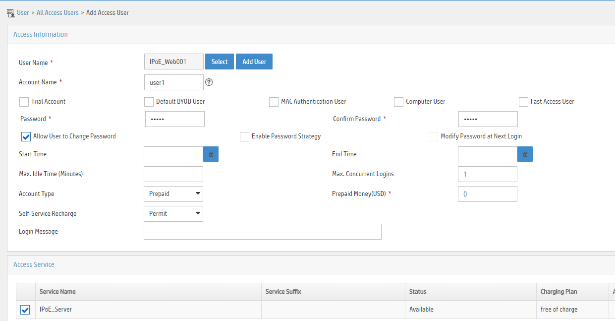
5. Add an access user:
a. Select Access User > All Access Users from the navigation tree to open the access user page.
b. Click Add to open the page as shown in Figure 8.
c. Select IPoE_Web001 for the username.
d. Enter the account name user1.
e. Enter the password pass1.
f. Select the access service IPoE_Server.
Figure 8 Adding an access user
Configuring the portal server
The following section uses an IMC server as an example to describe how to configure the portal server. The configuration procedure might vary by IMC version. For the exact configuration procedure, see the guide for the specific IMC version. The configuration procedure in this section is only for your reference.
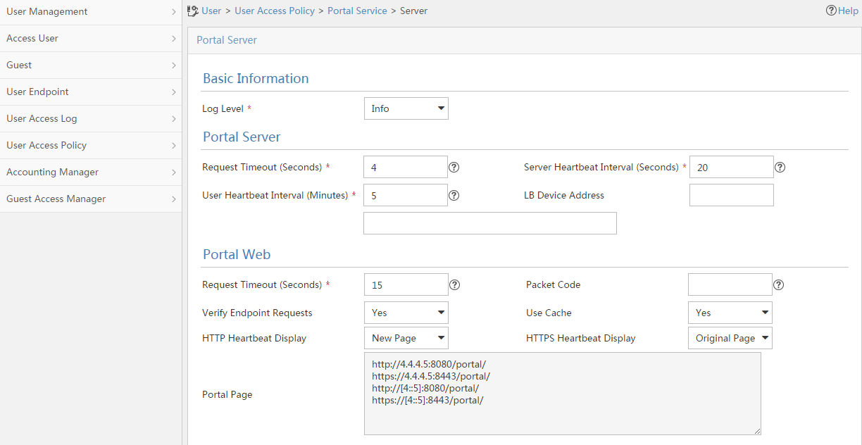
1. Configure the portal homepage:
a. Select User Access Policy > Portal Service > Server from the navigation tree to open the portal server configuration page, as shown in Figure 9.
b. Click OK.
Figure 9 Portal server configuration page
2. Configure portal authentication source IP address range:
a. Select User Access Policy > Portal Service > IP Group from the navigation tree to open the portal IP address group configuration page.
b. Click Add to open the page as shown in Figure 10.
c. Enter the IP group name IPoE_Web_User.
d. Enter the start IP address (192.168.0.1) and end IP address (192.168.0.255) of the IP group. Make sure the host IP address is in the IP group.
e. Click OK.
Figure 10 Adding an IP address group (IPv4)

a. Select User Access Policy > Portal Service > IP Group from the navigation tree to open the portal IP address group configuration page.
b. Click Add to open the page as shown in Figure 11.
c. Enter the IP group name IPoE_Web_User-2.
d. Select Yes from the IPv6 list.
e. Enter the start IP address (192::1) and end IP address (192::FFFF) of the IP group. Make sure the host IPv6 address is in the IP group.
f. Click OK.
Figure 11 Adding an IP address group (IPv6)

3. Add a portal device:
a. Select User Access Policy > Portal Service > Device from the navigation tree to open the portal device configuration page.
b. Click Add to open the page as shown in Figure 12.
c. Enter the device name NAS.
d. Enter the IP address of the portal packets' outgoing interface GigabitEthernet 3/1/1 (4.4.4.2).
e. Enter the key 123456.
f. Select Directly Connect for access method.
g. Click OK.
Figure 12 Adding a portal device (IPv4)

a. Select User Access Policy > Portal Service > Device from the navigation tree to open the portal device configuration page.
b. Click Add to open the page as shown in Figure 13.
c. Enter the device name NAS-2.
d. Select Portal 3.0 from the Version list.
e. Enter the IP address of the portal packets' outgoing interface GigabitEthernet 3/1/1 (4::2).
f. Enter the key 123456.
g. Select Directly Connect for access method.
h. Click OK.
Figure 13 Adding a portal device (IPv6)

4. Associate the portal device with the IP address group:
a. Select User Access Policy > Portal Service > Device from the navigation tree to open the portal device configuration page.
b. Click the icon in the Port Group Information Management column of device NAS to open the port group configuration page, as shown in Figure 14.
c. Click Add to open the page as shown in Figure 15.
d. Enter the port group name group.
e. Select the configured IP address group IPoE_Web_User. Make sure the IP address used by the user to access the network is within this IP address group.
f. Click OK.

Figure 15 Port group configuration (IPv4)

a. Select User Access Policy > Portal Service > Device from the navigation tree to open the portal device configuration page.
b. Click the icon in the Port Group Information Management column of device NAS-2 to open the port group configuration page, as shown in Figure 14.
c. Click Add to open the page as shown in Figure 16.
d. Enter the port group name group-2.
e. Select the configured IP address group IPoE_Web_User-2. Make sure the IPv6 address used by the user to access the network is within this IPv6 address group.
f. Click OK.
Figure 16 Port group configuration (IPv6)

Verifying the configuration
# Display IPoE session information to verify that the host has passed preauthentication and obtained IPv4 address 192.168.0.2 and IPv6 address 192::2.
[BRAS] display ip subscriber session verbose
Basic:
Description : -
Username : 001b21a80949
Domain : dm1
VPN instance : N/A
IP address : 192.168.0.2
IPv6 address : 192::2
User address type : N/A
MAC address : 001b-21a8-0949
Service-VLAN/Customer-VLAN : -/-
Access interface : GE3/1/2
User ID : 0x30000004
VPI/VCI(for ATM) : -/-
VSI Index : -
VSI link ID : -
VXLAN ID : -
DNS servers : N/A
IPv6 DNS servers : N/A
DHCP lease : 86400 sec
DHCP remain lease : 86383 sec
DHCPv6 lease : 2592000 sec
DHCPv6 remain lease : 2591981 sec
Access time : May 27 00:48:51 2018
Online time(hh:mm:ss) : 00:00:19
Service node : Slot 3 CPU 0
Authentication type : Web pre-auth
IPv4 access type : DHCP
IPv6 access type : DHCP
IPv4 detect state : Detecting
IPv6 detect state : Detecting
State : Online
AAA:
ITA policy name : N/A
IP pool : pool1
IPv6 pool : pool2
IPv6 nd prefix pool : N/A
Primary DNS server : N/A
Secondary DNS server : N/A
Primary IPv6 DNS server : N/A
Secondary IPv6 DNS server : N/A
Session idle cut : N/A
Session duration : N/A, remaining: N/A
Traffic quota : N/A
Traffic remained : N/A
Acct start-fail action : Online
Acct update-fail action : Online
Acct quota-out action : Offline
Dual-stack accounting mode : Merge
Max IPv4 multicast addresses: 4
IPv4 multicast address list : N/A
Max IPv6 multicast addresses: 4
IPv6 multicast address list : N/A
Accounting start time : May 27 00:48:51 2018
Redirect URL : http://www.h3c.web.com
Subscriber ID : -
QoS:
User profile : N/A
Session group profile : N/A
User group ACL : web (active)
Inbound CAR : N/A
Outbound CAR : N/A
Inbound user priority : N/A
Outbound user priority : N/A
Flow statistic:
Uplink packets/bytes : 0/0
Downlink packets/bytes : 0/0
IPv6 uplink packets/bytes : 0/0
IPv6 downlink packets/bytes : 0/0
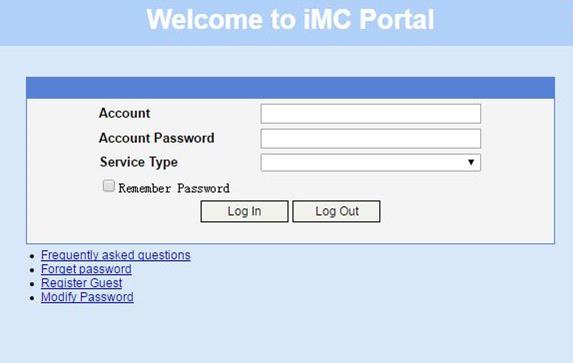
As shown in Figure 17, the Web login page opens after preauthentication. Enter the username and password on the page.
# Display IPoE session information to verify that the host has passed Web authentication and come online.
[BRAS] display ip subscriber session verbose
Basic:
Description : -
Username : user1@dm2
Domain : dm2
VPN instance : N/A
IP address : 192.168.0.2
IPv6 address : 192::2
User address type : N/A
MAC address : 001b-21a8-0949
Service-VLAN/Customer-VLAN : -/-
Access interface : GE3/1/2
User ID : 0x30000004
VPI/VCI(for ATM) : -/-
VSI Index : -
VSI link ID : -
VXLAN ID : -
DNS servers : N/A
IPv6 DNS servers : N/A
DHCP lease : 86400 sec
DHCP remain lease : 86356 sec
DHCPv6 lease : 2592000 sec
DHCPv6 remain lease : 2591954 sec
Access time : May 27 00:48:51 2018
Online time(hh:mm:ss) : 00:00:04
Service node : Slot 3 CPU 0
Authentication type : Web
IPv4 access type : DHCP
IPv6 access type : DHCP
IPv4 detect state : Detecting
IPv6 detect state : Detecting
State : Online
AAA:
ITA policy name : N/A
IP pool : pool1
IPv6 pool : pool2
IPv6 nd prefix pool : N/A
Primary DNS server : N/A
Secondary DNS server : N/A
Primary IPv6 DNS server : N/A
Secondary IPv6 DNS server : N/A
Session idle cut : N/A
Session duration : 86400 sec, remaining: 86395 sec
Traffic quota : N/A
Traffic remained : N/A
Acct start-fail action : Online
Acct update-fail action : Online
Acct quota-out action : Offline
Dual-stack accounting mode : Merge
Max IPv4 multicast addresses: 4
IPv4 multicast address list : N/A
Max IPv6 multicast addresses: 4
IPv6 multicast address list : N/A
Accounting start time : May 27 00:49:32 2018
Subscriber ID : -
QoS:
User profile : car (active)
Session group profile : N/A
User group ACL : N/A
Inbound CAR : N/A
Outbound CAR : N/A
Inbound user priority : N/A
Outbound user priority : N/A
Flow statistic:
Uplink packets/bytes : 0/0
Downlink packets/bytes : 0/0
IPv6 uplink packets/bytes : 0/0
IPv6 downlink packets/bytes : 0/0
Configuration files
· DHCP server:
#
dhcp enable
#
ipv6 dhcp server forbidden-address 192::1
#
dhcp server ip-pool pool1
gateway-list 192.168.0.1
network 192.168.0.0 mask 255.255.255.0
forbidden-ip 192.168.0.1
#
ipv6 dhcp pool pool2
network 192::/64
#
interface GigabitEthernet3/1/1
port link-mode route
ip address 4.4.4.3 255.255.255.0
ipv6 dhcp select server
ipv6 address 4::3/64
#
ip route-static 192.168.0.0 24 4.4.4.2
ipv6 route-static 192:: 64 4::2
#
· Router A (BRAS):
#
dhcp enable
dhcp relay client-information record
undo dhcp relay client-information refresh enable
#
traffic classifier neiwang operator or
if-match acl name neiwang
if-match acl ipv6 name neiwang
#
traffic classifier neiwang_out operator or
if-match acl name neiwang_out
if-match acl ipv6 name neiwang_out
#
traffic classifier web_deny operator or
if-match acl name ip
if-match acl ipv6 name ip
#
traffic classifier web_http operator or
if-match acl name web_http
if-match acl ipv6 name web_http
#
traffic classifier web_https operator or
if-match acl name web_https
if-match acl ipv6 name web_https
#
traffic classifier web_out operator or
if-match acl name web_out
if-match acl ipv6 name web_out
#
traffic classifier web_permit operator or
if-match acl name web_permit
if-match acl ipv6 name web_permit
#
traffic behavior neiwang
filter permit
#
traffic behavior neiwang_out
filter permit
#
traffic behavior web_deny
filter deny
free account
#
traffic behavior web_http
redirect http-to-cpu
#
traffic behavior web_https
redirect https-to-cpu
#
traffic behavior web_out
filter permit
free account
#
traffic behavior web_permit
filter permit
free account
#
qos policy out
classifier web_out behavior web_out
classifier neiwang_out behavior neiwang_out
classifier web_deny behavior web_deny
#
qos policy web
classifier web_permit behavior web_permit
classifier neiwang behavior neiwang
classifier web_http behavior web_http
classifier web_https behavior web_https
classifier web_deny behavior web_deny
#
interface GigabitEthernet3/1/1
ip address 4.4.4.2 255.255.255.0
ipv6 address 4::2/64
#
interface GigabitEthernet3/1/2
port link-mode route
dhcp select relay proxy
ipv6 dhcp select relay
ipv6 dhcp relay client-information record
ipv6 dhcp relay release-agent
ipv6 nd ra prefix 192::/64 no-advertise
ipv6 address auto link-local
ipv6 nd autoconfig managed-address-flag
ipv6 nd autoconfig other-flag
undo ipv6 nd ra halt
ip subscriber l2-connected enable
ip subscriber authentication-method web
ip subscriber pre-auth domain dm1
ip subscriber web-auth domain dm2
#
qos apply policy web global inbound
qos apply policy out global outbound
#
dhcp server ip-pool pool1
gateway-list 192.168.0.1 export-route
remote-server 4.4.4.3
#
ipv6 dhcp pool pool2
gateway-list 192::1
remote-server 4::3
#
acl advanced name ip
rule 0 permit ip user-group web
#
acl advanced name neiwang
rule 0 permit ip destination 4.4.4.1 0 user-group web
#
acl advanced name neiwang_out
rule 0 permit ip source 4.4.4.1 0 user-group web
#
acl advanced name web_http
rule 0 permit tcp destination-port eq www user-group web
#
acl advanced name web_https
rule 0 permit tcp destination-port eq 443 user-group web
#
acl advanced name web_out
rule 0 permit ip source 4.4.4.5 0 user-group web
#
acl advanced name web_permit
rule 0 permit ip destination 4.4.4.5 0 user-group web
#
acl ipv6 advanced name ip
rule 0 permit ipv6 user-group web
#
acl ipv6 advanced name neiwang
rule 0 permit ipv6 destination 4::1/128 user-group web
#
acl ipv6 advanced name neiwang_out
rule 0 permit ipv6 source 4::1/128 user-group web
#
acl ipv6 advanced name web_http
rule 0 permit tcp destination-port eq www user-group web
#
acl ipv6 advanced name web_https
rule 0 permit tcp destination-port eq 443 user-group web
#
acl ipv6 advanced name web_out
rule 0 permit ipv6 source 4::5/128 user-group web
#
acl ipv6 advanced name web_permit
rule 0 permit ipv6 destination 4::5/128 user-group web
#
user-profile car
qos car inbound any cir 5210 cbs 325625 ebs 0
#
radius scheme rs1
primary authentication 4.4.4.5
primary accounting 4.4.4.5
key authentication cipher $c$3$FhQVcgn3kq1exL0CdTzatcgc9xF9vL3ZOw==
key accounting cipher $c$3$ntIHBRM4ZkG+2JRZQTdKmNl0kYJmhZz5Zg==
user-name-format without-domain
#
radius dynamic-author server
client ip 4.4.4.5 key cipher $c$3$lYC2ERe8ts2gtE6M2xfoDDB8NmGw6J9v/Q==
#
domain name dm1
authorization-attribute user-group web
authorization-attribute ip-pool pool1
authorization-attribute ipv6-pool pool2
authentication ipoe none
authorization ipoe none
accounting ipoe none
web-server url http://www.h3c.web.com
#
domain name dm2
authorization-attribute user-profile car
authentication ipoe radius-scheme rs1
authorization ipoe radius-scheme rs1
accounting ipoe radius-scheme rs1
#
user-group web
#
portal server newpt1
ip 4.4.4.5 key cipher $c$3$UnoFeLybwld9jDwLnHJQptDE7YZry2EVlw==
#
portal server newpt2
ipv6 4::5 key cipher $c$3$HxisNWeML9fhYRS+7umwGbYwAkL+KGiCjw==
#
http-redirect https-port 11111
#
Example: Configuring IPoE transparent MAC authentication for dual-stack users
Network configuration
As shown in Figure 18:
· The host accesses the BRAS as a DHCP client though a Layer 2 device. It obtains configuration information from the DHCP server through the BRAS.
· The BRAS performs AAA for the host through the RADIUS server.
· A server installed with H3C IMC acts as the portal authentication server and the portal Web server.
· A RADIUS server that supports MAC binding acts as the authentication, authorization, and accounting server and performs MAC binding.
· The FTP server is an internal network server.
· Limit the access rate to 5 Mbps for the user after passing Web authentication.

Analysis
To meet bandwidth requirements of users, this example authorizes user profiles for rate limiting.
To improve the forwarding efficiency, classify the traffic in the IPoE preauthentication domain into HTTP traffic, HTTPS traffic, and common IP packets and assign them to different queues. Configure three class-behavior associations to process the traffic to be sent to the CPU:
· Configure a class to match HTTP traffic from the user group created in the preauthentication domain, and associate the class with a behavior containing the redirect http-to-cpu action.
· Configure a class to match HTTPS traffic from the user group created in the preauthentication domain, and associate the class with a behavior containing the redirect https-to-cpu action.
· Configure a class to match IP traffic from the user group created in the preauthentication domain, and associate the class with a behavior containing the redirect cpu action.
When a BRAS access user goes offline, the DHCP relay agent needs to query the relay user address entry of the user. If the entry exists, the DHCP relay agent sends Release packets to the DHCP server to notify the DHCP server to release the user's address lease. For this purpose, execute the dhcp relay client-information record command to enable recording client information in relay entries.
Restrictions and guidelines
The DHCP server in this example is simulated by a device. As a best practice, use a dedicated DHCP server in actual applications.
By default, the HTTPS redirect listening port number is not configured. To configure the HTTPS port number, execute the http-redirect https-port command. Make sure the listening port number does not conflict with existing port numbers.
Procedures
Configuring IP addresses and routes
As shown in Figure 18, configure IP addresses for interfaces, and make sure the BRAS and servers can reach each other at Layer 3.
Configuring the DNS server
Configure the DNS server properly, so that the server can parse the IPv4 URL or IPv6 URL corresponding to the Web authentication page http://www.h3c.web.com according to the first protocol stack that comes online of the IPoE dual-stack user. (Details not shown.)
Configuring the DHCP server
Configuring a DHCPv4 address pool
# Enable DHCP.
<DHCP> system-view
[DHCP] dhcp enable
# Create a DHCPv4 address pool named pool1 and enter its view.
[DHCP] dhcp server ip-pool pool1
# Specify primary subnet 192.168.0.0/24 for dynamic allocation in address pool pool1.
[DHCP-dhcp-pool-pool1] network 192.168.0.0 24
# Specify gateway address 192.168.0.1 in address pool pool1.
[DHCP-dhcp-pool-pool1] gateway-list 192.168.0.1
# Exclude DHCP address 192.168.0.1 from dynamic allocation in address pool pool1.
[DHCP-dhcp-pool-pool1] forbidden-dhcp 192.168.0.1
[DHCP-dhcp-pool-pool1] quit
# Configure a static route to specify the next hop of DHCPv4 replies destined to network segment 192.168.0.0 as the IP address of the interface connected to the DHCPv4 client, 4.4.4.2.
[DHCP] ip route-static 192.168.0.0 24 4.4.4.2
Configuring a DHCPv6 address pool
# Create a DHCPv6 address pool named pool2 and enter its view.
[DHCP] ipv6 dhcp pool pool2
# Specify primary subnet 192::0/64 for dynamic allocation in address pool pool2.
[DHCP-dhcpv6-pool-pool2] network 192::0/64
[DHCP-dhcpv6-pool-pool2] quit
# Exclude IP address 192::1 from dynamic allocation in address pool pool2.
[DHCP] ipv6 dhcp server forbidden-address 192::1
# Enable the DHCPv6 server on GigabitEthernet 3/1/1.
[DHCP] interface gigabitethernet 3/1/1
[DHCP-GigabitEthernet3/1/1] ipv6 dhcp select server
[DHCP-GigabitEthernet3/1/1] quit
# Configure a static route to specify the next hop of DHCPv6 replies destined to network segment 192::0 as the IP address of the interface connected to the DHCPv6 client, 4::2.
[DHCP] ipv6 route-static 192::0 64 4::2
Configuring the BRAS
Configuring the DHCP relay agent
# Enable DHCP.
[BRAS] dhcp enable
# Enable recording client information in relay entries.
[BRAS] dhcp relay client-information record
# Disable the DHCP relay agent to periodically refresh dynamic relay entries.
[BRAS] undo dhcp relay client-information refresh enable
# Create a DHCP relay address pool named pool1.
[BRAS] dhcp server ip-pool pool1
# Specify the gateway address in address pool pool1.
[BRAS-dhcp-pool-pool1] gateway-list 192.168.0.1 24 export-route
# Specify DHCP server 4.4.4.3 in address pool pool1.
[BRAS-dhcp-pool-pool1] remote-server 4.4.4.3
[BRAS-dhcp-pool-pool1] quit
# Create a DHCP relay address pool named pool2.
[BRAS] ipv6 dhcp pool pool2
# Specify gateway address 192::1 in address pool pool2.
[BRAS-dhcpv6-pool-pool2] gateway-list 192::1
# Specify DHCP server 4::3 in DHCP relay address pool pool2.
[BRAS-dhcpv6-pool-pool2] remote-server 4::3
[BRAS-dhcpv6-pool-pool2] quit
# Enable the DHCPv4 relay agent on GigabitEthernet 3/1/2.
[BRAS] interface gigabitethernet 3/1/2
[BRAS–GigabitEthernet3/1/2] dhcp select relay proxy
# Automatically generate a link-local address for GigabitEthernet 3/1/2.
[BRAS–GigabitEthernet3/1/2] ipv6 address auto link-local
# Enable the DHCPv6 relay agent on GigabitEthernet 3/1/2.
[BRAS–GigabitEthernet3/1/2] ipv6 dhcp select relay
# Enable recording client information in DHCPv6 relay entries.
[BRAS–GigabitEthernet3/1/2] ipv6 dhcp relay client-information record
# Enable IPv6 release notification.
[BRAS–GigabitEthernet3/1/2] ipv6 dhcp relay release-agent
# Disable RA message suppression on GigabitEthernet 3/1/2.
[BRAS–GigabitEthernet3/1/2] undo ipv6 nd ra halt
# Set the managed address configuration flag (M) to 1 in RA advertisements to be sent. Then, the host uses a DHCPv6 server to obtain IPv6 addresses.
[BRAS–GigabitEthernet3/1/2] ipv6 nd autoconfig managed-address-flag
# Set the other stateful configuration flag (O) to 1 in RA advertisements to be sent. Then, the host uses a DHCPv6 server to obtain configuration information other than IPv6 addresses.
[BRAS–GigabitEthernet3/1/2] ipv6 nd autoconfig other-flag
# Disable GigabitEthernet 3/1/2 from advertising the specified prefix in RA messages, preventing the endpoint from obtaining a temporary IPv6 address. In an IPv6 network, an endpoint might use a temporary IPv6 address for IPoE Web authentication, which will cause authentication failure.
[BRAS–GigabitEthernet3/1/2] ipv6 nd ra prefix 192::/64 no-advertise
[BRAS–GigabitEthernet3/1/2] quit
Configuring the portal servers
# Configure the IP address of the IPv4 portal authentication server newpt1 as 4.4.4.5 and the plaintext key 123456.
[BRAS] portal server newpt1
[BRAS-portal-server-newpt1] ip 4.4.4.5 key simple 123456
[BRAS-portal-server-newpt1] quit
# Configure the IPv6 address of the IPv6 portal authentication server newpt2 as 4::5 and the plaintext key 123456.
[BRAS] portal server newpt2
[BRAS-portal-server-newpt2] ipv6 4::5 key simple 123456
[BRAS-portal-server-newpt2] quit
Specifying the HTTPS redirect listening port number
# Specify 11111 as the HTTPS redirect listening port number.
[BRAS] http-redirect https-port 11111
Creating a local user group
# Create a local user group named web.
[BRAS] user-group web
New user group added.
[BRAS-ugroup-web] quit
Configuring QoS
1. Configure ACLs for preauthentication:
# Create an IPv4 and IPv6 advanced ACL named web_permit separately. Configure a rule to permit all packets destined for the portal server from users in user group web.
[BRAS] acl advanced name web_permit
[BRAS-acl-ipv4-adv-web_permit] rule 0 permit ip destination 4.4.4.5 0 user-group web
[BRAS-acl-ipv4-adv-web_permit] quit
[BRAS] acl ipv6 advanced name web_permit
[BRAS-acl-ipv6-adv-web_permit] rule 0 permit ipv6 destination 4::5 128 user-group web
[BRAS-acl-ipv6-adv-web_permit] quit
# Create an IPv4 and IPv6 advanced ACL named neiwang separately. Configure a rule to permit all packets destined for the internal network server from users in user group web.
[BRAS] acl advanced name neiwang
[BRAS-acl-ipv4-adv-neiwang] rule 0 permit ip destination 4.4.4.6 0 user-group web
[BRAS-acl-ipv4-adv-neiwang] quit
[BRAS] acl ipv6 advanced name neiwang
[BRAS-acl-ipv6-adv-neiwang] rule 0 permit ipv6 destination 4::6 128 user-group web
[BRAS-acl-ipv6-adv-neiwang] quit
# Create an IPv4 and IPv6 advanced ACL named web_http separately. Configure a rule to permit TCP packets with the destination port 80 (HTTP packets) from users in user group web.
[BRAS] acl advanced name web_http
[BRAS-acl-ipv4-adv-web_http] rule 0 permit tcp destination-port eq www user-group web
[BRAS-acl-ipv4-adv-web_http] quit
[BRAS] acl ipv6 advanced name web_http
[BRAS-acl-ipv6-adv-web_http] rule 0 permit tcp destination-port eq www user-group web
[BRAS-acl-ipv6-adv-web_http] quit
# Create an IPv4 and IPv6 advanced ACL named web_https separately, and configure a rule to permit TCP packets with the destination port 443 (HTTPS packets) from users in user group web.
[BRAS] acl advanced name web_https
[BRAS-acl-ipv4-adv-web_https] rule 0 permit tcp destination-port eq 443 user-group web
[BRAS-acl-ipv4-adv-web_https] quit
[BRAS] acl ipv6 advanced name web_https
[BRAS-acl-ipv6-adv-web_https] rule 0 permit tcp destination-port eq 443 user-group web
[BRAS-acl-ipv6-adv-web_https] quit
# Create an IPv4 and IPv6 advanced ACL named ip separately, and configure a rule to permit IP packets from users in user group web.
[BRAS] acl advanced name ip
[BRAS-acl-ipv4-adv-ip] rule 0 permit ip user-group web
[BRAS-acl-ipv4-adv-ip] quit
[BRAS] acl ipv6 advanced name ip
[BRAS-acl-ipv6-adv-ip] rule 0 permit ipv6 user-group web
[BRAS-acl-ipv6-adv-ip] quit
# Create an IPv4 and IPv6 advanced ACL named neiwang_out separately, and configure a rule to permit IP packets from the internal network server in user group web.
[BRAS] acl advanced name neiwang_out
[BRAS-acl-ipv4-adv-neiwang_out] rule 0 permit ip source 4.4.4.6 0 user-group web
[BRAS-acl-ipv4-adv-neiwang_out] quit
[BRAS] acl ipv6 advanced name neiwang_out
[BRAS-acl-ipv6-adv-neiwang_out] rule 0 permit ipv6 source 4::6 128 user-group web
[BRAS-acl-ipv6-adv-neiwang_out] quit
# Create an IPv4 and IPv6 advanced ACL named web_out separately, and configure a rule to permit IP packets from the portal server in user group web.
[BRAS] acl advanced name web_out
[BRAS-acl-ipv4-adv-web_out] rule 0 permit ip source 4.4.4.5 0 user-group web
[BRAS-acl-ipv4-adv-web_out] quit
[BRAS] acl ipv6 advanced name web_out
[BRAS-acl-ipv6-adv-web_out] rule 0 permit ipv6 source 4::5 128 user-group web
[BRAS-acl-ipv6-adv-web_out] quit
2. Configure QoS traffic classes for preauthentication users:
# Create the traffic class web_permit and specify ACL web_permit as the match criterion.
[BRAS] traffic classifier web_permit operator or
[BRAS-classifier-web_permit] if-match acl name web_permit
[BRAS-classifier-web_permit] if-match acl ipv6 name web_permit
[BRAS-classifier-web_permit] quit
# Create the traffic class neiwang and specify ACL neiwang as the match criterion.
[BRAS] traffic classifier neiwang operator or
[BRAS-classifier-neiwang] if-match acl name neiwang
[BRAS-classifier-neiwang] if-match acl ipv6 name neiwang
[BRAS-classifier-neiwang] quit
# Create the traffic class web_http and specify ACL web_http as the match criterion.
[BRAS] traffic classifier web_http operator or
[BRAS-classifier-web_http] if-match acl name web_http
[BRAS-classifier-web_http] if-match acl ipv6 name web_http
[BRAS-classifier-web_http] quit
# Create the traffic class web_https and specify ACL web_https as the match criterion.
[BRAS] traffic classifier web_https operator or
[BRAS-classifier-web_https] if-match acl name web_https
[BRAS-classifier-web_https] if-match acl ipv6 name web_https
[BRAS-classifier-web_https] quit
# Create the traffic class ip_cpu and specify ACL ip as the match criterion.
[BRAS] traffic classifier ip_cpu operator or
[BRAS-classifier-ip_cpu] if-match acl name ip
[BRAS-classifier-ip_cpu] if-match acl ipv6 name ip
[BRAS-classifier-ip_cpu] quit
# Create the traffic class ip_deny and specify ACL ip as the match criterion.
[BRAS] traffic classifier ip_deny operator or
[BRAS-classifier-ip_deny] if-match acl name ip
[BRAS-classifier-ip_deny] if-match acl ipv6 name ip
[BRAS-classifier-ip_deny] quit
# Create the traffic class neiwang_out and specify ACL neiwang_out as the match criterion.
[BRAS] traffic classifier neiwang_out operator or
[BRAS-classifier-neiwang_out] if-match acl name neiwang_out
[BRAS-classifier-neiwang_out] if-match acl ipv6 name neiwang_out
[BRAS-classifier-neiwang_out] quit
# Create the traffic class web_out and specify ACL web_out as the match criterion.
[BRAS] traffic classifier web_out operator or
[BRAS-classifier-web_out] if-match acl name web_out
[BRAS-classifier-web_out] if-match acl ipv6 name web_out
[BRAS-classifier-web_out] quit
3. Configure QoS traffic behaviors:
# Configure the traffic behavior web_permit to permit traffic to pass through without rate limiting or accounting.
[BRAS] traffic behavior web_permit
[BRAS-behavior-web_permit] filter permit
[BRAS-behavior-web_permit] free account
[BRAS-behavior-web_permit] quit
# Configure the traffic behavior neiwang to permit traffic to pass through.
[BRAS] traffic behavior neiwang
[BRAS-behavior-neiwang] filter permit
[BRAS-behavior-neiwang] quit
# Configure the traffic behavior web_http to redirect HTTP packets to the CPU.
[BRAS] traffic behavior web_http
[BRAS-behavior-web_http] redirect http-to-cpu
[BRAS-behavior-web_http] quit
# Configure the traffic behavior web_https to redirect HTTPS packets to the CPU.
[BRAS] traffic behavior web_https
[BRAS-behavior-web_https] redirect https-to-cpu
[BRAS-behavior-web_https] quit
# Configure the traffic behavior web_cpu to redirect IP packets to the CPU.
[BRAS] traffic behavior web_cpu
[BRAS-behavior-web_cpu] redirect cpu
[BRAS-behavior-web_cpu] quit
# Configure the traffic behavior web_deny to deny traffic.
[BRAS] traffic behavior web_deny
[BRAS-behavior-web_deny] filter deny
[BRAS-behavior-web_deny] free account
[BRAS-behavior-web_deny] quit
# Configure the traffic behavior neiwang_out to permit traffic to pass through.
[BRAS] traffic behavior neiwang_out
[BRAS-behavior-neiwang_out] filter permit
[BRAS-behavior-neiwang_out] quit
# Configure the traffic behavior web_out to permit traffic without rate limiting or traffic accounting.
[BRAS] traffic behavior web_out
[BRAS-behavior-web_out] filter permit
[BRAS-behavior-web_out] free account
[BRAS-behavior-web_out] quit
4. Configure the QoS policies:
# Create a QoS policy named web.
[BRAS] qos policy web
# Associate the traffic class web_permit with the traffic behavior web_permit.
[BRAS-qospolicy-web] classifier web_permit behavior web_permit
# Associate the traffic class neiwang with the traffic behavior neiwang.
[BRAS-qospolicy-web] classifier neiwang behavior neiwang
# Associate the traffic class web_http with the traffic behavior web_http.
[BRAS-qospolicy-web] classifier web_http behavior web_http
# Associate the traffic class web_https with the traffic behavior web_https.
[BRAS-qospolicy-web] classifier web_https behavior web_https
# Associate the traffic class ip_cpu with the traffic behavior web_cpu.
[BRAS-qospolicy-web] classifier ip_cpu behavior web_cpu
# Associate the traffic class ip_deny with the traffic behavior web_deny.
[BRAS-qospolicy-web] classifier ip_deny behavior web_deny
[BRAS-qospolicy-web] quit
# Configure a QoS policy named out.
[BRAS] qos policy out
# Associate the traffic class web_out with the traffic behavior web_out. Associate the traffic class neiwang_out with the traffic behavior neiwang_out. Associate the traffic class ip_deny with the traffic behavior web_deny.
[BRAS-qospolicy-out] classifier web_out behavior web_out
[BRAS-qospolicy-out] classifier neiwang_out behavior neiwang_out
[BRAS-qospolicy-out] classifier ip_deny behavior web_deny
[BRAS-qospolicy-out] quit
5. Apply the QoS policies:
# Apply the QoS Policy web to the inbound traffic globally.
[BRAS] qos apply policy web global inbound
# Apply the QoS Policy out to the outbound traffic globally.
[BRAS] qos apply policy out global outbound
6. Verify that the applied QoS policies take effect:
# Display the configuration and running status of the QoS policy applied to the inbound traffic globally.
[BRAS] display qos policy global slot 3 inbound
Direction: Inbound
Policy: web
Classifier: web_permit
Operator: OR
Rule(s) :
If-match acl name web_permit
If-match acl ipv6 name web_permit
Behavior: web_permit
Filter enable: Permit
Free account enable
Classifier: neiwang
Operator: OR
Rule(s) :
If-match acl name neiwang
If-match acl ipv6 name neiwang
Behavior: neiwang
Filter enable: Permit
Classifier: web_http
Operator: OR
Rule(s) :
If-match acl name web_http
If-match acl ipv6 name web_http
Behavior: web_http
Redirecting:
Redirect http to CPU
Classifier: web_https
Operator: OR
Rule(s) :
If-match acl name web_https
If-match acl ipv6 name web_https
Behavior: web_https
Redirecting:
Redirect https to CPU
Classifier: ip_cpu
Operator: OR
Rule(s) :
If-match acl name ip
If-match acl ipv6 name ip
Behavior: web_cpu
Redirecting:
Redirect to the CPU
Classifier: ip_deny
Operator: OR
Rule(s) :
If-match acl name ip
If-match acl ipv6 name ip
Behavior: web_deny
Filter enable: Deny
Free account enable
# Display the configuration and running status of the QoS policy applied to the outbound traffic globally.
[BRAS] display qos policy global slot 3 outbound
Direction: Outbound
Policy: out
Classifier: web_out
Operator: OR
Rule(s) :
If-match acl name web_out
If-match acl ipv6 name web_out
Behavior: web_out
Filter enable: Permit
Free account enable
Classifier: neiwang_out
Operator: OR
Rule(s) :
If-match acl name neiwang_out
If-match acl ipv6 name neiwang_out
Behavior: neiwang_out
Filter enable: Permit
Classifier: ip_deny
Operator: OR
Rule(s) :
If-match acl name ip
If-match acl ipv6 name ip
Behavior: web_deny
Filter enable: Deny
Free account enable
Configuring a RADIUS scheme
# Create a RADIUS scheme named rs1 and enter its view.
[BRAS] radius scheme rs1
# Configure primary servers and keys for authentication and accounting.
[BRAS-radius-rs1] primary authentication 4.4.4.1
[BRAS-radius-rs1] primary accounting 4.4.4.1
[BRAS-radius-rs1] key authentication simple radius
[BRAS-radius-rs1] key accounting simple radius
# Exclude the ISP name from the username sent to the RADIUS server.
[BRAS-radius-rs1] user-name-format without-domain
[BRAS-radius-rs1] quit
# Set the IP address of the RADIUS DAE client to 4.4.4.1, and set the shared key to radius for the RADIUS DAE client to exchange DAE packets.
[BRAS] radius dynamic-author server
[BRAS-radius-da-server] client ip 4.4.4.1 key simple radius
[BRAS-radius-da-server] quit
Configuring the user profile
# Create a user profile named car. Configure the user profile to perform traffic policing for incoming traffic of online users, with the CIR as 5210 kbps and CBS as 325625 bytes.
[BRAS] user-profile car
[BRAS-user-profile-car] qos car inbound any cir 5210 cbs 325625
[BRAS-user-profile-car] quit
Configuring the preauthentication ISP domain and Web authentication ISP domain
# Configure the ISP domain dm1 for IPoE user preauthentication.
[BRAS] domain name dm1
[BRAS-isp-dm1] authentication ipoe none
[BRAS-isp-dm1] authorization ipoe none
[BRAS-isp-dm1] accounting ipoe none
# Configure the authorized user group and IP address pools in preauthentication ISP domain dm1.
[BRAS-isp-dm1] authorization-attribute user-group web
[BRAS-isp-dm1] authorization-attribute ip-pool pool1
[BRAS-isp-dm1] authorization-attribute ipv6-pool pool2
# Configure the Web authentication page URL in ISP domain dm1.
[BRAS-isp-dm1] web-server url http://www.h3c.web.com
[BRAS-isp-dm1] quit
# Configure the ISP domain dm2 for IPoE user Web authentication.
[BRAS] domain name dm2
[BRAS-isp-dm2] authentication ipoe radius-scheme rs1
[BRAS-isp-dm2] authorization ipoe radius-scheme rs1
[BRAS-isp-dm2] accounting ipoe radius-scheme rs1
[BRAS-isp-dm2] authorization-attribute user-profile car
[BRAS-isp-dm2] quit
Configuring IPoE
# Enable IPoE and configure Layer 2 access mode on GigabitEthernet 3/1/2.
[BRAS] interface gigabitethernet 3/1/2
[BRAS–GigabitEthernet3/1/2] ip subscriber l2-connected enable
# Configure Web MAC authentication for IPoE users on GigabitEthernet 3/1/2.
[BRAS–GigabitEthernet3/1/2] ip subscriber authentication-method web mac-auth
The operation may cut all users on this interface. Continue?[Y/N]:y
# Configure the ISP domain dm1 for preauthentication and the ISP domain dm2 for Web authentication and Web MAC authentication on GigabitEthernet 3/1/2.
[BRAS–GigabitEthernet3/1/2] ip subscriber pre-auth domain dm1
[BRAS–GigabitEthernet3/1/2] ip subscriber web-auth domain dm2
[BRAS–GigabitEthernet3/1/2] ip subscriber mac-auth domain dm2
[BRAS–GigabitEthernet3/1/2] quit
Configuring the RADIUS server
For how to configure AAA and MAC binding on the RADIUS server, see the RADIUS server configuration guide.
Configuring the portal server
The following section uses an IMC server as an example to describe how to configure the portal server. The configuration procedure might vary by IMC version. For the exact configuration procedure, see the guide for the specific IMC version. The configuration procedure in this section is only for your reference.
1. Configure the portal homepage:
a. Select User Access Policy > Portal Service > Server from the navigation tree to open the portal server configuration page, as shown in Figure 19.
b. Click OK.
Figure 19 Portal server configuration page

2. Configure portal authentication source IP address range:
a. Select User Access Policy > Portal Service > IP Group from the navigation tree to open the portal IP address group configuration page.
b. Click Add to open the page as shown in Figure 20.
c. Enter the IP group name IPoE_Web_User.
d. Enter the start IP address (192.168.0.1) and end IP address (192.168.0.255) of the IP group. Make sure the host IP address is in the IP group.
e. Click OK.
Figure 20 Adding an IP address group (IPv4)

a. Select User Access Policy > Portal Service > IP Group from the navigation tree to open the portal IP address group configuration page.
b. Click Add to open the page as shown in Figure 21.
c. Enter the IP group name IPoE_Web_User-2.
d. Select Yes from the IPv6 list.
e. Enter the start IP address (192::1) and end IP address (192::FFFF) of the IP group. Make sure the host IPv6 address is in the IP group.
f. Click OK.
Figure 21 Adding an IP address group (IPv6)

3. Add a portal device:
a. Select User Access Policy > Portal Service > Device from the navigation tree to open the portal device configuration page.
b. Click Add to open the page as shown in Figure 22.
c. Enter the device name NAS.
d. Enter the IP address of the portal packets' outgoing interface GigabitEthernet 3/1/1 (4.4.4.2).
e. Enter the key 123456.
f. Select Directly Connect for access method.
g. Click OK.
Figure 22 Adding a portal device (IPv4)

a. Select User Access Policy > Portal Service > Device from the navigation tree to open the portal device configuration page.
b. Click Add to open the page as shown in Figure 23.
c. Enter the device name NAS-2.
d. Select Portal 3.0 from the Version list.
e. Enter the IP address of the portal packets' outgoing interface GigabitEthernet 3/1/1 (4::2).
f. Enter the key 123456.
g. Select Directly Connect for access method.
h. Click OK.
Figure 23 Adding a portal device (IPv6)

4. Associate the portal device with the IP address group:
a. Select User Access Policy > Portal Service > Device from the navigation tree to open the portal device configuration page.
b. Click the icon in the Port Group Information Management column of device NAS to open the port group configuration page, as shown in Figure 24.
c. Click Add to open the page as shown in Figure 25.
d. Enter the port group name group.
e. Select the configured IP address group IPoE_Web_User. Make sure the IP address used by the user to access the network is within this IP address group.
f. Click OK.
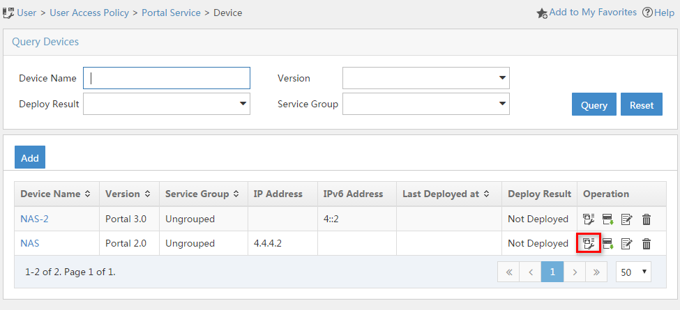
Figure 25 Port group configuration (IPv4)
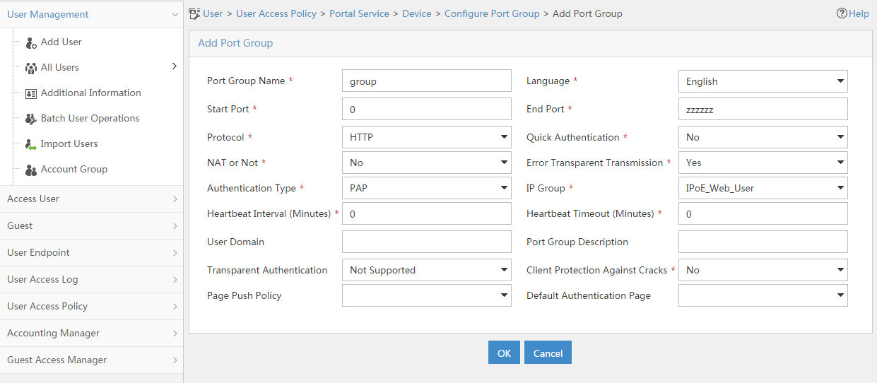
a. Select User Access Policy > Portal Service > Device from the navigation tree to open the portal device configuration page.
b. Click the icon in the Port Group Information Management column of device NAS-2 to open the port group configuration page, as shown in Figure 24.
c. Click Add to open the page as shown in Figure 26.
d. Enter the port group name group-2.
e. Select the configured IP address group IPoE_Web_User-2. Make sure the IPv6 address used by the user to access the network is within this IPv6 address group.
f. Click OK.
Figure 26 Port group configuration (IPv6)

5. From the navigation tree, select User Access Manager > Service Parameters > Validate System Configuration to validate the settings.
Verifying the configuration
# Display IPoE session information to verify that the host has passed preauthentication and obtained IPv4 address 192.168.0.2 and IPv6 address 192::2.
[BRAS] display ip subscriber session verbose
Basic:
Description : -
Username : 001b21a80949
Domain : dm1
VPN instance : N/A
IP address : 192.168.0.2
IPv6 address : 192::2
User address type : N/A
MAC address : 001b-21a8-0949
Service-VLAN/Customer-VLAN : -/-
Access interface : GE3/1/2
User ID : 0x30000004
VPI/VCI(for ATM) : -/-
VSI Index : -
VSI link ID : -
VXLAN ID : -
DNS servers : N/A
IPv6 DNS servers : N/A
DHCP lease : 86400 sec
DHCP remain lease : 86383 sec
DHCPv6 lease : 2592000 sec
DHCPv6 remain lease : 2591981 sec
Access time : May 27 00:48:51 2018
Online time(hh:mm:ss) : 00:00:19
Service node : Slot 3 CPU 0
Authentication type : Web pre-auth
IPv4 access type : DHCP
IPv6 access type : DHCP
IPv4 detect state : Detecting
IPv6 detect state : Detecting
State : Online
AAA:
ITA policy name : N/A
IP pool : pool1
IPv6 pool : pool2
IPv6 nd prefix pool : N/A
Primary DNS server : N/A
Secondary DNS server : N/A
Primary IPv6 DNS server : N/A
Secondary IPv6 DNS server : N/A
Session idle cut : N/A
Session duration : N/A, remaining: N/A
Traffic quota : N/A
Traffic remained : N/A
Acct start-fail action : Online
Acct update-fail action : Online
Acct quota-out action : Offline
Dual-stack accounting mode : Merge
Max IPv4 multicast addresses: 4
IPv4 multicast address list : N/A
Max IPv6 multicast addresses: 4
IPv6 multicast address list : N/A
Accounting start time : May 27 00:48:51 2018
Redirect URL : http://www.h3c.web.com
Subscriber ID : -
QoS:
User profile : N/A
Session group profile : N/A
User group ACL : web (active)
Inbound CAR : N/A
Outbound CAR : N/A
Inbound user priority : N/A
Outbound user priority : N/A
Flow statistic:
Uplink packets/bytes : 0/0
Downlink packets/bytes : 0/0
IPv6 uplink packets/bytes : 0/0
IPv6 downlink packets/bytes : 0/0
As shown in Figure 27, the Web login page opens after preauthentication. Enter the username and password on the page.
# Display IPoE session information to verify that the host has passed Web authentication and come online.
[BRAS] display ip subscriber session verbose
Basic:
Description : -
Username : user1@dm2
Domain : dm2
VPN instance : N/A
IP address : 192.168.0.2
IPv6 address : 192::2
User address type : N/A
MAC address : 001b-21a8-0949
Service-VLAN/Customer-VLAN : -/-
Access interface : GE3/1/2
User ID : 0x30000004
VPI/VCI(for ATM) : -/-
VSI Index : -
VSI link ID : -
VXLAN ID : -
DNS servers : N/A
IPv6 DNS servers : N/A
DHCP lease : 86400 sec
DHCP remain lease : 86356 sec
DHCPv6 lease : 2592000 sec
DHCPv6 remain lease : 2591954 sec
Access time : May 27 00:49:20 2018
Online time(hh:mm:ss) : 00:00:04
Service node : Slot 3 CPU 0
Authentication type : Web
IPv4 access type : DHCP
IPv6 access type : DHCP
IPv4 detect state : Detecting
IPv6 detect state : Detecting
State : Online
AAA:
ITA policy name : N/A
IP pool : pool1
IPv6 pool : pool2
IPv6 nd prefix pool : N/A
Primary DNS server : N/A
Secondary DNS server : N/A
Primary IPv6 DNS server : N/A
Secondary IPv6 DNS server : N/A
Session idle cut : N/A
Session duration : 86400 sec, remaining: 86395 sec
Traffic quota : N/A
Traffic remained : N/A
Acct start-fail action : Online
Acct update-fail action : Online
Acct quota-out action : Offline
Dual-stack accounting mode : Merge
Max IPv4 multicast addresses: 4
IPv4 multicast address list : N/A
Max IPv6 multicast addresses: 4
IPv6 multicast address list : N/A
Accounting start time : May 27 00:49:20 2018
Subscriber ID : -
QoS:
User profile : car (active)
Session group profile : N/A
User group ACL : N/A
Inbound CAR : N/A
Outbound CAR : N/A
Inbound user priority : N/A
Outbound user priority : N/A
Flow statistic:
Uplink packets/bytes : 0/0
Downlink packets/bytes : 0/0
IPv6 uplink packets/bytes : 0/0
IPv6 downlink packets/bytes : 0/0
# Click Log Out on the Web login page as shown in Figure 27.
# Verify that the user returns to the preauthentication status.
[BRAS] display ip subscriber session verbose
Basic:
Description : -
Username : 001b21a80949
Domain : dm1
VPN instance : N/A
IP address : 192.168.0.2
IPv6 address : 192::2
User address type : N/A
MAC address : 001b-21a8-0949
Service-VLAN/Customer-VLAN : -/-
Access interface : GE3/1/2
User ID : 0x30000004
VPI/VCI(for ATM) : -/-
VSI Index : -
VSI link ID : -
VXLAN ID : -
DNS servers : N/A
IPv6 DNS servers : N/A
DHCP lease : 86400 sec
DHCP remain lease : 86383 sec
DHCPv6 lease : 2592000 sec
DHCPv6 remain lease : 2591981 sec
Access time : May 27 00:49:30 2018
Online time(hh:mm:ss) : 00:00:19
Service node : Slot 3 CPU 0
Authentication type : Web pre-auth
IPv4 access type : DHCP
IPv6 access type : DHCP
IPv4 detect state : Detecting
IPv6 detect state : Detecting
State : Online
AAA:
ITA policy name : N/A
IP pool : pool1
IPv6 pool : pool2
IPv6 nd prefix pool : N/A
Primary DNS server : N/A
Secondary DNS server : N/A
Primary IPv6 DNS server : N/A
Secondary IPv6 DNS server : N/A
Session idle cut : N/A
Session duration : N/A, remaining: N/A
Traffic quota : N/A
Traffic remained : N/A
Acct start-fail action : Online
Acct update-fail action : Online
Acct quota-out action : Offline
Dual-stack accounting mode : Merge
Max IPv4 multicast addresses: 4
IPv4 multicast address list : N/A
Max IPv6 multicast addresses: 4
IPv6 multicast address list : N/A
Accounting start time : May 27 00:49:30 2018
Redirect URL : http://www.h3c.web.com
Subscriber ID : -
QoS:
User profile : N/A
Session group profile : N/A
User group ACL : web (active)
Inbound CAR : N/A
Outbound CAR : N/A
Inbound user priority : N/A
Outbound user priority : N/A
Flow statistic:
Uplink packets/bytes : 0/0
Downlink packets/bytes : 0/0
IPv6 uplink packets/bytes : 0/0
IPv6 downlink packets/bytes : 0/0
# Open the browser, and enter an address randomly, for example, http://63.1.1.240.
# Verify that the user has come online through IPoE Web MAC authentication.
[BRAS] display ip subscriber session verbose
Basic:
Description : -
Username : web
Domain : dm2
VPN instance : N/A
IP address : 192.168.0.2
IPv6 address : 192::2
User address type : N/A
MAC address : 001b-21a8-0949
Service-VLAN/Customer-VLAN : -/-
Access interface : GE3/1/2
User ID : 0x30000004
VPI/VCI(for ATM) : -/-
VSI Index : -
VSI link ID : -
VXLAN ID : -
DNS servers : N/A
IPv6 DNS servers : N/A
DHCP lease : 86400 sec
DHCP remain lease : 86356 sec
DHCPv6 lease : 2592000 sec
DHCPv6 remain lease : 2591954 sec
Access time : May 27 00:50:01 2018
Online time(hh:mm:ss) : 00:00:04
Service node : Slot 3 CPU 0
Authentication type : Web mac-auth
IPv4 access type : DHCP
IPv6 access type : DHCP
IPv4 detect state : Detecting
IPv6 detect state : Detecting
State : Online
AAA:
ITA policy name : N/A
IP pool : pool1
IPv6 pool : pool2
IPv6 nd prefix pool : N/A
Primary DNS server : N/A
Secondary DNS server : N/A
Primary IPv6 DNS server : N/A
Secondary IPv6 DNS server : N/A
Session idle cut : N/A
Session duration : 86400 sec, remaining: 86395 sec
Traffic quota : N/A
Traffic remained : N/A
Acct start-fail action : Online
Acct update-fail action : Online
Acct quota-out action : Offline
Dual-stack accounting mode : Merge
Max IPv4 multicast addresses: 4
IPv4 multicast address list : N/A
Max IPv6 multicast addresses: 4
IPv6 multicast address list : N/A
Accounting start time : May 27 00:50:01 2018
Subscriber ID : -
QoS:
User profile : car (active)
Session group profile : N/A
User group ACL : N/A
Inbound CAR : N/A
Outbound CAR : N/A
Inbound user priority : N/A
Outbound user priority : N/A
Flow statistic:
Uplink packets/bytes : 0/0
Downlink packets/bytes : 0/0
IPv6 uplink packets/bytes : 0/0
IPv6 downlink packets/bytes : 0/0
Configuration files
· DHCP server:
#
dhcp enable
#
ipv6 dhcp server forbidden-address 192::1
#
dhcp server ip-pool pool1
gateway-list 192.168.0.1
network 192.168.0.0 mask 255.255.255.0
forbidden-ip 192.168.0.1
#
ipv6 dhcp pool pool2
network 192::/64
#
interface GigabitEthernet3/1/1
port link-mode route
ip address 4.4.4.3 255.255.255.0
ipv6 dhcp select server
ipv6 address 4::3/64
#
ip route-static 192.168.0.0 24 4.4.4.2
ipv6 route-static 192:: 64 4::2
#
· Router A (BRAS):
#
dhcp enable
dhcp relay client-information record
undo dhcp relay client-information refresh enable
#
traffic classifier ip_cpu operator or
if-match acl name ip
if-match acl ipv6 name ip
#
traffic classifier ip_deny operator or
if-match acl name ip
if-match acl ipv6 name ip
#
traffic classifier neiwang operator or
if-match acl name neiwang
if-match acl ipv6 name neiwang
#
traffic classifier neiwang_out operator or
if-match acl name neiwang_out
if-match acl ipv6 name neiwang_out
#
traffic classifier web_http operator or
if-match acl name web_http
if-match acl ipv6 name web_http
#
traffic classifier web_https operator or
if-match acl name web_https
if-match acl ipv6 name web_https
#
traffic classifier web_out operator or
if-match acl name web_out
if-match acl ipv6 name web_out
#
traffic classifier web_permit operator or
if-match acl name web_permit
if-match acl ipv6 name web_permit
#
traffic behavior neiwang
filter permit
#
traffic behavior neiwang_out
filter permit
#
traffic behavior web_cpu
redirect cpu
#
traffic behavior web_deny
filter deny
free account
#
traffic behavior web_http
redirect http-to-cpu
#
traffic behavior web_https
redirect https-to-cpu
#
traffic behavior web_out
filter permit
free account
#
traffic behavior web_permit
filter permit
free account
#
qos policy out
classifier web_out behavior web_out
classifier neiwang_out behavior neiwang_out
classifier ip_deny behavior web_deny
#
qos policy web
classifier web_permit behavior web_permit
classifier neiwang behavior neiwang
classifier web_http behavior web_http
classifier web_https behavior web_https
classifier ip_cpu behavior web_cpu
classifier ip_deny behavior web_deny
#
interface GigabitEthernet3/1/1
ip address 4.4.4.2 255.255.255.0
ipv6 address 4::2/64
#
interface GigabitEthernet3/1/2
port link-mode route
dhcp select relay proxy
ipv6 dhcp select relay
ipv6 dhcp relay client-information record
ipv6 dhcp relay release-agent
ipv6 nd ra prefix 192::/64 no-advertise
ipv6 address auto link-local
ipv6 nd autoconfig managed-address-flag
ipv6 nd autoconfig other-flag
undo ipv6 nd ra halt
ip subscriber l2-connected enable
ip subscriber authentication-method web mac-auth
ip subscriber pre-auth domain dm1
ip subscriber mac-auth domain dm2
ip subscriber web-auth domain dm2
#
qos apply policy web global inbound
qos apply policy out global outbound
#
dhcp server ip-pool pool1
gateway-list 192.168.0.1 export-route
remote-server 4.4.4.3
#
ipv6 dhcp pool pool2
gateway-list 192::1
remote-server 4::3
#
acl advanced name ip
rule 0 permit ip user-group web
#
acl advanced name neiwang
rule 0 permit ip destination 4.4.4.6 0 user-group web
#
acl advanced name neiwang_out
rule 0 permit ip source 4.4.4.6 0 user-group web
#
acl advanced name web_http
rule 0 permit tcp destination-port eq www user-group web
#
acl advanced name web_https
rule 0 permit tcp destination-port eq 443 user-group web
#
acl advanced name web_out
rule 0 permit ip source 4.4.4.5 0 user-group web
#
acl advanced name web_permit
rule 0 permit ip destination 4.4.4.5 0 user-group web
#
acl ipv6 advanced name ip
rule 0 permit ipv6 user-group web
#
acl ipv6 advanced name neiwang
rule 0 permit ipv6 destination 4::6/128 user-group web
#
acl ipv6 advanced name neiwang_out
rule 0 permit ipv6 source 4::6/128 user-group web
#
acl ipv6 advanced name web_http
rule 0 permit tcp destination-port eq www user-group web
#
acl ipv6 advanced name web_https
rule 0 permit tcp destination-port eq 443 user-group web
#
acl ipv6 advanced name web_out
rule 0 permit ipv6 source 4::5/128 user-group web
#
acl ipv6 advanced name web_permit
rule 0 permit ipv6 destination 4::5/128 user-group web
#
user-profile car
qos car inbound any cir 5210 cbs 325625 ebs 0
#
radius scheme rs1
primary authentication 4.4.4.1
primary accounting 4.4.4.1
key authentication cipher $c$3$FhQVcgn3kq1exL0CdTzatcgc9xF9vL3ZOw==
key accounting cipher $c$3$ntIHBRM4ZkG+2JRZQTdKmNl0kYJmhZz5Zg==
user-name-format without-domain
#
radius dynamic-author server
client ip 4.4.4.1 key cipher $c$3$lYC2ERe8ts2gtE6M2xfoDDB8NmGw6J9v/Q==
#
domain name dm1
authorization-attribute user-group web
authorization-attribute ip-pool pool1
authorization-attribute ipv6-pool pool2
authentication ipoe none
authorization ipoe none
accounting ipoe none
web-server url http://www.h3c.web.com
#
domain name dm2
authorization-attribute user-profile car
authentication ipoe radius-scheme rs1
authorization ipoe radius-scheme rs1
accounting ipoe radius-scheme rs1
#
user-group web
#
portal server newpt1
ip 4.4.4.5 key cipher $c$3$UnoFeLybwld9jDwLnHJQptDE7YZry2EVlw==
#
portal server newpt2
ipv6 4::5 key cipher $c$3$HxisNWeML9fhYRS+7umwGbYwAkL+KGiCjw==
#
http-redirect https-port 11111
#
Example: Configuring multiple egress VPNs and ITA in a BRAS campus network (inline)
Network configuration
As shown in Figure 28, the dormitory area and office area of a campus network are directly attached to BRAS. As the border device, PE2 is connected to different service providers ISP1 and ISP2. Configure the BRAS campus network to meet the following requirements:
· Before a user in the dormitory area or office area passes PPPoE dialup authentication, the user can access only the internal network with the rate limit of 5 Mbps. Accounting is not performed for the user accessing the internal network.
· After passing the PPPoE dialup authentication, the user can access both the internal network and the Internet. The rate limit for accessing the internal network is still 5 Mbps and no accounting is performed. The school provides three monthly Internet access plans, with the speeds of 2 Mbps, 5 Mbps, and 10 Mbps separately. In this example, suppose users A, B, C, and D select the 2 Mbps, 5 Mbps, 5 Mbps, and 10 Mbps plans, respectively.
· Users use the dialup client in the operating systems for PPPoE dialup authentication.
· When a user performs PPPoE dialup, the username carries the ISP domain name by adding a suffix @ISP1 or @ISP2. BRAS specifies a fixed ISP egress interface for the user according to the domain name of the user.

|
IP address |
IP address |
||||
|
PE1 (BRAS) |
Loop0 |
1.1.1.9/32 |
GE3/0/2 |
101.1.1.1/24 |
|
|
GE3/1/1.1 |
5.5.5.1/24 |
GE3/0/3 |
202.1.1.1/24 |
||
|
GE3/1/2 |
10.1.1.1/24 |
CE1 |
GE3/0/1 |
101.1.1.2/24 |
|
|
GE3/1/3 |
4.4.4.1/24 |
CE2 |
GE3/0/1 |
202.1.1.2/24 |
|
|
P |
Loop0 |
2.2.2.9/32 |
|||
|
GE3/0/1 |
10.1.4.1/24 |
||||
Analysis
· For BRAS to select an ISP egress interface for a user according to the domain name carried in the username, you can authorize a VPN to the user in the ISP domain and assign different ISP egress interfaces to different VPNs.
· To implement differentiated accounting policies for users, define four accounting levels in ITA (for example, specify levels 1 through 4 for the internal network access of 5 Mbps, Internet access of 2 Mbps, Internet access of 5 Mbps, and Internet access of 10 Mbps) separately, and define different prices for different ITA levels.
· To distinguish the internal network traffic and Internet traffic after users pass PPPoE dialup authentication, you can use an ACL (ACL 3001 in this example) to match the specific internal network traffic, and then use an ACL (ACL 3002 in this example) to match traffic except internal traffic (the Internet traffic by default).
· When a PPPoE access user goes offline, the DHCP relay agent needs to query the relay user address entry of the user. If the entry exists, the DHCP relay agent sends Release packets to the DHCP server to notify the DHCP server to release the user's address lease. For this purpose, execute the dhcp relay client-information record command to enable recording client information in relay entries.
Restrictions and guidelines
· When an interface is bound to a VPN instance, the settings (including IP address) on the interface will be cleared. Therefore, first bind an interface to a VPN instance, and then configure other settings on the interface.
· The class-behavior associations in a QoS policy are executed in the order they are configured. To ensure preferential processing of the internal network traffic, make sure the class-behavior associations for internal network traffic are configured before the class-behavior associations for Internet traffic.
· If authorization attributes (for example, address pool, user group, and VPN) are configured both on the RADIUS server and in an ISP domain, the attributes configured on the RADIUS server apply. If the idle-cut attribute is configured both on the RADIUS server and in an ISP domain, the configuration in the ISP domain on the BRAS applies. In this example, all the authorization attributes have been configured in ISP domains. In a live network, configure the RADIUS server to authorize attributes or configure attributes in ISP domains as needed.
Procedures
Configuring the RADIUS server
This section uses the Linux Free RADIUS server as an example.
# Configure the RADIUS client. Add the following contents to the clients.conf file.
client 4.4.4.1/32 {
ipaddr = 4.4.4.1
netmask=32
secret=123456
}
The contents above configure the RADIUS client IP address as 4.4.4.1 and configure the shared key as 123456.
# Configure users. Add the following contents to the users file.
User1@isp1 Cleartext-Password :="pass1"
User1@isp2 Cleartext-Password :="pass1"
User2@isp1 Cleartext-Password :="pass2"
User2@isp2 Cleartext-Password :="pass2"
User3@isp1 Cleartext-Password :="pass3"
User3@isp2 Cleartext-Password :="pass3"
User4@isp1 Cleartext-Password :="pass4"
User4@isp2 Cleartext-Password :="pass4"
The contents above show that Host A, Host B, Host C, and Host D can select to use suffix @isp1 or @isp2 for PPPoE dialup.
Configuring MPLS L3VPN
In this example, Router A acts as PE1 in the MPLS L3VPN configuration and acts as the PPPoE server in the BRAS configuration. For ease of understanding, Router A is described as PE1 in the MPLS L3VPN configuration section and described as BRAS in the BRAS configuration section.
Configure an IGP protocol (OSPF in this example) on the MPLS backbone to ensure IP connectivity within the backbone
1. Configure PE 1:
# Configure IP addresses for the loopback interface and the backbone network interface.
<PE1> system-view
[PE1] interface loopback 0
[PE1-LoopBack0] ip address 1.1.1.9 32
[PE1-LoopBack0] quit
[PE1] interface gigabitethernet 3/1/2
[PE1-GigabitEthernet3/1/2] ip address 10.1.1.1 24
[PE1-GigabitEthernet3/1/2] quit
# Enable OSPF on the interfaces attached to the backbone network side in the area.
[PE1] ospf
[PE1-ospf-1] area 0
[PE1-ospf-1-area-0.0.0.0] network 10.1.1.0 0.0.0.255
[PE1-ospf-1-area-0.0.0.0] network 1.1.1.9 0.0.0.0
[PE1-ospf-1-area-0.0.0.0] quit
[PE1-ospf-1] quit
2. Configure the P device:
# Configure IP addresses for the loopback interface and the backbone network interface.
<P> system-view
[P] interface loopback 0
[P-LoopBack0] ip address 2.2.2.9 32
[P-LoopBack0] quit
[P] interface gigabitethernet 3/0/2
[P-GigabitEthernet3/0/2] ip address 10.1.1.2 24
[P-GigabitEthernet3/0/2] quit
[P] interface gigabitethernet 3/0/1
[P-GigabitEthernet3/0/1] ip address 10.1.4.1 24
[P-GigabitEthernet3/0/1] quit
# Enable OSPF on the interfaces attached to the backbone network side in the area.
[P] ospf
[P-ospf-1] area 0
[P-ospf-1-area-0.0.0.0] network 10.1.1.0 0.0.0.255
[P-ospf-1-area-0.0.0.0] network 10.1.4.0 0.0.0.255
[P-ospf-1-area-0.0.0.0] network 2.2.2.9 0.0.0.0
[P-ospf-1-area-0.0.0.0] quit
[P-ospf-1] quit
3. Configure PE 2:
# Configure IP addresses for the loopback interface and the backbone network interface.
<PE2> system-view
[PE2] interface loopback 0
[PE2-LoopBack0] ip address 3.3.3.9 32
[PE2-LoopBack0] quit
[PE2] interface gigabitethernet 3/0/1
[PE2-GigabitEthernet3/0/1] ip address 10.1.4.2 24
[PE2-GigabitEthernet3/0/1] quit
# Enable OSPF on the interfaces attached to the backbone network side in the area.
[PE2] ospf
[PE2-ospf-1] area 0
[PE2-ospf-1-area-0.0.0.0] network 10.1.4.0 0.0.0.255
[PE2-ospf-1-area-0.0.0.0] network 3.3.3.9 0.0.0.0
[PE2-ospf-1-area-0.0.0.0] quit
[PE2-ospf-1] quit
4. Execute the display ospf peer command to verify that OSPF adjacencies in Full state have been established between PE 1, P, and PE 2. Execute the display ip routing-table command to verify that the PEs have learned the routes to the loopback interfaces of each other.
Use PE1 as an example.
[PE1] display ospf peer verbose
OSPF Process 1 with Router ID 1.1.1.9
Neighbors
Area 0.0.0.0 interface 10.1.1.1(GE3/1/2)'s neighbors
Router ID: 2.2.2.9 Address: 10.1.1.2 GR State: Normal
State: Full Mode: Nbr is Master Priority: 1
DR: 10.1.1.2 BDR: 10.1.1.1 MTU: 0
Options is 0x02 (-|-|-|-|-|-|E|-)
Dead timer due in 38 sec
Neighbor is up for 17:30:25
Authentication Sequence: [ 0 ]
Neighbor state change count: 6
BFD status: Disabled
[PE1] display ip routing-table protocol ospf
Summary Count : 5
OSPF Routing table Status : <Active>
Summary Count : 3
Destination/Mask Proto Pre Cost NextHop Interface
2.2.2.9/32 O_INTRA 10 1 10.1.1.2 GE3/1/2
3.3.3.9/32 O_INTRA 10 2 10.1.1.2 GE3/1/2
10.1.4.0/24 O_INTRA 10 2 10.1.1.2 GE3/1/2
OSPF Routing table Status : <Inactive>
Summary Count : 2
Destination/Mask Proto Pre Cost NextHop Interface
1.1.1.9/32 O_INTRA 10 0 1.1.1.9 Loop0
10.1.1.0/24 O_INTRA 10 1 10.1.1.1 GE3/0/2
Configure basic MPLS and MPLS LDP on the MPLS backbone to establish LDP LSPs
1. Configure PE 1:
[PE1] mpls lsr-id 1.1.1.9
[PE1] mpls ldp
[PE1-ldp] quit
[PE1] interface gigabitethernet 3/1/2
[PE1-GigabitEthernet3/1/2] mpls enable
[PE1-GigabitEthernet3/1/2] mpls ldp enable
[PE1-GigabitEthernet3/1/2] quit
2. Configure the P device:
[P] mpls lsr-id 2.2.2.9
[P] mpls ldp
[P-ldp] quit
[P] interface gigabitethernet 3/0/2
[P-GigabitEthernet3/0/2] mpls enable
[P-GigabitEthernet3/0/2] mpls ldp enable
[P-GigabitEthernet3/0/2] quit
[P] interface gigabitethernet 3/0/1
[P-GigabitEthernet3/0/1] mpls enable
[P-GigabitEthernet3/0/1] mpls ldp enable
[P-GigabitEthernet3/0/1] quit
3. Configure PE 2:
[PE2] mpls lsr-id 3.3.3.9
[PE2] mpls ldp
[PE2-ldp] quit
[PE2] interface gigabitethernet 3/0/1
[PE2-GigabitEthernet3/0/1] mpls enable
[PE2-GigabitEthernet3/0/1] mpls ldp enable
[PE2-GigabitEthernet3/0/1] quit
4. Execute the display mpls ldp peer command to verify that LDP sessions in Operational state have been established between PE 1, P, and PE 2. Execute the display mpls ldp lsp command to verify that the LSPs have been established by LDP.
Use PE1 as an example.
[PE1] display mpls ldp peer
Total number of peers: 1
Peer LDP ID State Role GR MD5 KA Sent/Rcvd
2.2.2.9:0 Operational Passive Off Off 5/5
[PE1] display mpls ldp lsp
Status Flags: * - stale, L - liberal, B - backup
FECs: 4 Ingress: 1 Transit: 1 Egress: 3
FEC In/Out Label Nexthop OutInterface
1.1.1.9/32 3/-
-/1151(L)
2.2.2.9/32 -/3 10.1.1.2 GE3/1/2
1151/3 10.1.1.2 GE3/1/2
3.3.3.9/32 -/1150 10.1.1.2 GE3/1/2
1150/1150 10.1.1.2 GE3/1/2
Configuring VPN instances on PEs to allow CE access
1. Configure PE 1:
# Create VPN instance named vpn_isp1 for ISP 1.
[PE1] ip vpn-instance vpn_isp1
# Configure the RD as 100:1 for the VPN instance. The RD is used for generating VPNv4 routes and distinguishing routes of different users on the same network segment.
[PE1-vpn-instance-vpn_isp1] route-distinguisher 100:1
# Configure import target 111:1 and export target 222:1 for the VPN instance. (To differentiate the meanings of export target and import target, this section uses different values for the two targets. For ease of management, you can configure the same value for the two targets. )
[PE1-vpn-instance-vpn_isp1] vpn-target 111:1 import-extcommunity
[PE1-vpn-instance-vpn_isp1] vpn-target 222:1 export-extcommunity
[PE1-vpn-instance-vpn_isp1] quit
# Create VPN instance named vpn_isp2 for ISP 2. Configure RD 200:1, import target 333:1, and export target 444:1 for the VPN instance.
[PE1] ip vpn-instance vpn_isp2
[PE1-vpn-instance-vpn_isp2] route-distinguisher 200:1
[PE1-vpn-instance-vpn_isp2] vpn-target 333:1 import-extcommunity
[PE1-vpn-instance-vpn_isp2] vpn-target 444:1 export-extcommunity
[PE1-vpn-instance-vpn_isp2] quit
|
|
NOTE: After a user successfully passes PPPoE dialup authentication, PE 1 will add the host route of the user to the routing table of the user's VPN instance. Therefore, you do not need to bind the user access interface to a VPN instance on PE 1. |
2. Configure PE 2:
# Create VPN instance named vpn_isp1 for ISP 2 on PE 2.
[PE2] ip vpn-instance vpn_isp1
# Configure an RD for the VPN instance. For ease of identification, as a best practice, set the same RD as that on PE 1.
[PE2-vpn-instance-vpn_isp1] route-distinguisher 100:1
# Configure the import target and export target for the VPN instance, which must be the same as the export target and import target on PE 1.
[PE2-vpn-instance-vpn_isp1] vpn-target 222:1 import-extcommunity
[PE2-vpn-instance-vpn_isp1] vpn-target 111:1 export-extcommunity
[PE2-vpn-instance-vpn_isp1] quit
# Create VPN instance named vpn_isp2 for ISP 2. Configure RD 200:1, import target 444:1, and export target 333:1 for the VPN instance.
[PE2] ip vpn-instance vpn_isp2
[PE2-vpn-instance-vpn_isp2] route-distinguisher 200:1
[PE2-vpn-instance-vpn_isp2] vpn-target 444:1 import-extcommunity
[PE2-vpn-instance-vpn_isp2] vpn-target 333:1 export-extcommunity
[PE2-vpn-instance-vpn_isp2] quit
# Bind GigabitEthernet 3/0/2 and GigabitEthernet 3/0/3 to VPN instance vpn_isp1 and VPN instance vpn_isp2, respectively.
[PE2] interface gigabitethernet 3/0/2
[PE2-GigabitEthernet3/0/2] ip binding vpn-instance vpn_isp1
[PE2-GigabitEthernet3/0/2] ip address 101.1.1.1 24
[PE2-GigabitEthernet3/0/2] quit
[PE2] interface gigabitethernet 3/0/3
[PE2-GigabitEthernet3/0/3] ip binding vpn-instance vpn_isp2
[PE2-GigabitEthernet3/0/3] ip address 202.1.1.1 24
[PE2-GigabitEthernet3/0/3] quit
3. Configure IP addresses for interfaces on the CE as shown in Figure 28. (Details not shown.)
Establishing EBGP peer relationships between PEs and CEs, and redistributing VPN routes into BGP
1. Configure PE 1:
# Create BGP process 100 on PE 1.
[PE1] bgp 100
|
|
NOTE: After a user successfully passes PPPoE dialup authentication, the BRAS acting as PE 1 adds the host route corresponding to the IP address assigned to the user to the routing table of the VPN instance to which the user belongs. Therefore, you only need to redistribute the direct routes of the host into the routing table of the BGP-VPN instance. |
# Redistribute the direct routes in the routing table of VPN instance vpn_isp1 on PE 1 into the routing table of the BGP-VPN instance.
[PE1-bgp-default] ip vpn-instance vpn_isp1
[PE1-bgp-default-vpn_isp1] address-family ipv4 unicast
[PE1-bgp-default-ipv4-vpn_isp1] import-route direct
[PE1-bgp-default-ipv4-vpn_isp1] quit
[PE1-bgp-default-vpn_isp1] quit
# Redistribute the direct routes in the routing table of VPN instance vpn_isp2 on PE 1 into the routing table of the BGP-VPN instance.
[PE1-bgp-default] ip vpn-instance vpn_isp2
[PE1-bgp-default-vpn_isp2] address-family ipv4 unicast
[PE1-bgp-default-ipv4-vpn_isp2] import-route direct
[PE1-bgp-default-ipv4-vpn_isp2] quit
[PE1-bgp-default-vpn_isp2] quit
[PE1-bgp-default] quit
2. Configure PE 2:
# Create BGP process 100 on PE 2.
[PE2] bgp 100
# Specify CE 1 as the peer. Redistribute the direct routes in the routing table of PE 2 into the routing table of the BGP-VPN instance.
[PE2-bgp-default] ip vpn-instance vpn_isp1
[PE2-bgp-default-vpn_isp1] peer 101.1.1.2 as-number 65430
[PE2-bgp-default-vpn_isp1] address-family ipv4 unicast
[PE2-bgp-default-ipv4-vpn_isp1] peer 101.1.1.2 enable
[PE2-bgp-default-ipv4-vpn_isp1] import-route direct
[PE2-bgp-default-ipv4-vpn_isp1] quit
[PE2-bgp-default-vpn_isp1] quit
# Specify CE 2 as the peer. Redistribute the direct routes in the routing table of PE 2 into the routing table of the BGP-VPN instance.
[PE2-bgp-default] ip vpn-instance vpn_isp2
[PE2-bgp-default-vpn_isp2] peer 202.1.1.2 as-number 65430
[PE2-bgp-default-vpn_isp2] address-family ipv4 unicast
[PE2-bgp-default-ipv4-vpn_isp2] peer 202.1.1.2 enable
[PE2-bgp-default-ipv4-vpn_isp2] import-route direct
[PE2-bgp-default-ipv4-vpn_isp2] quit
[PE2-bgp-default-vpn_isp2] quit
[PE2-bgp-default] quit
3. Configure CE 1:
# Create BGP process 65430 on CE 1. Specify PE 1 as the peer with AS number 100.
<CE1> system-view
[CE1] bgp 65430
[CE1-bgp-default] peer 101.1.1.1 as-number 100
# Enable CE 1 to exchange routing information for an address family with peer 101.1.1.1.
[CE1-bgp-default] address-family ipv4 unicast
[CE1-bgp-default-ipv4] peer 101.1.1.1 enable
# Redistribute the direct route connected to the host on CE 1 into EBGP.
[CE1-bgp-default-ipv4] import-route direct
[CE1-bgp-default-ipv4] quit
[CE1-bgp-default] quit
4. Configure CE 2:
# Create BGP process 65430 on CE 2. Specify PE 2 as the peer with AS number 100.
<CE2> system-view
[CE2] bgp 65430
[CE2-bgp-default] peer 202.1.1.1 as-number 100
# Enable CE 2 to exchange routing information for an address family with peer 202.1.1.1.
[CE2-bgp-default] address-family ipv4 unicast
[CE2-bgp-default-ipv4] peer 202.1.1.1 enable
# Redistribute the direct route connected to the host on CE 2 into EBGP.
[CE2-bgp-default-ipv4] import-route direct
[CE2-bgp-default-ipv4] quit
[CE2-bgp-default] quit
Establishing MP-IBGP peer relationships between PEs
1. Configure PE 1:
# On PE 1, specify PE 2 as the BGP peer, and specify loopback 0 as the source interface for TCP connections to the peer.
[PE1] bgp 100
[PE1-bgp-default] peer 3.3.3.9 as-number 100
[PE1-bgp-default] peer 3.3.3.9 connect-interface loopback 0
# Enter BGP VPNv4 address family view, and specify PE 2 as the peer.
[PE1-bgp-default] address-family vpnv4
[PE1-bgp-default-vpnv4] peer 3.3.3.9 enable
[PE1-bgp-default-vpnv4] quit
[PE1-bgp-default] quit
2. Configure PE 2:
# On PE 2, specify PE 1 as the BGP peer, and specify loopback 0 as the source interface for TCP connections to the peer.
[PE2] bgp 100
[PE2-bgp-default] peer 1.1.1.9 as-number 100
[PE2-bgp-default] peer 1.1.1.9 connect-interface loopback 0
# Enter BGP VPNv4 address family view, and specify PE 1 as the peer.
[PE2-bgp-default] address-family vpnv4
[PE2-bgp-default-vpnv4] peer 1.1.1.9 enable
[PE2-bgp-default-vpnv4] quit
[PE2-bgp-default] quit
3. After the configuration is completed, execute the display bgp peer vpnv4 command to verify that the BGP peer relationships have been established between PEs and are in Established state.
[PE1] display bgp peer vpnv4
BGP local router ID: 1.1.1.9
Local AS number: 100
Total number of peers: 1 Peers in established state: 1
Peer AS MsgRcvd MsgSent OutQ PrefRcv Up/Down State
3.3.3.9 100 8 8 0 0 00:00:08 Established
4. Execute the display ip routing-table vpn-instance command on a PE to view the route destined to the peer CE 1.
Use vpn_isp1 as an example on PE1.
[PE1] display ip routing-table vpn-instance vpn_isp1
Destinations : 9 Routes : 9
Destination/Mask Proto Pre Cost NextHop Interface
0.0.0.0/32 Direct 0 0 127.0.0.1 InLoop0
101.1.1.0/24 BGP 255 0 3.3.3.9 GE3/1/2
127.0.0.0/8 Direct 0 0 127.0.0.1 InLoop0
127.0.0.0/32 Direct 0 0 127.0.0.1 InLoop0
127.0.0.1/32 Direct 0 0 127.0.0.1 InLoop0
127.255.255.255/32 Direct 0 0 127.0.0.1 InLoop0
224.0.0.0/4 Direct 0 0 0.0.0.0 NULL0
224.0.0.0/24 Direct 0 0 0.0.0.0 NULL0
255.255.255.255/32 Direct 0 0 127.0.0.1 InLoop0
Configuring the DHCP server
# Configure IP addresses for GigabitEthernet 3/0/1 as shown in Figure 28. (Details not shown.)
# Enable DHCP.
<DHCP> system-view
[DHCP] dhcp enable
# Create address pool pool1, which is used by users before performing authentication.
[DHCP] dhcp server ip-pool pool1
# Specify primary subnet 5.5.0.0/16 for dynamic allocation in the address pool. Specify gateway address 5.5.5.1 and DNS server address 8.8.8.8 in the address pool.
[DHCP-dhcp-pool-pool1] network 5.5.0.0 16
[DHCP-dhcp-pool-pool1] gateway-list 5.5.5.1
[DHCP-dhcp-pool-pool1] dns-list 8.8.8.8
# Exclude IP address 5.5.5.1 from dynamic allocation.
[DHCP-dhcp-pool-pool1] forbidden-ip 5.5.5.1
[DHCP-dhcp-pool-pool1] quit
# Create address pool pool2 for users in ISP domain isp1.
[DHCP] dhcp server ip-pool pool2
# Specify primary subnet 6.6.0.0/16 for dynamic allocation in the address pool. Specify gateway address 6.6.6.1 and DNS server address 8.8.8.8 in the address pool.
[DHCP-dhcp-pool-pool2] network 6.6.0.0 16
[DHCP-dhcp-pool-pool2] gateway-list 6.6.6.1
[DHCP-dhcp-pool-pool2] dns-list 8.8.8.8
# Exclude IP address 6.6.6.1 from dynamic allocation.
[DHCP-dhcp-pool-pool2] forbidden-ip 6.6.6.1
[DHCP-dhcp-pool-pool2] quit
# Create address pool pool3 for users in ISP domain isp2.
[DHCP] dhcp server ip-pool pool3
# Specify primary subnet 7.7.0.0/16 for dynamic allocation in the address pool. Specify gateway address 7.7.7.1 and DNS server address 8.8.8.8 in the address pool.
[DHCP-dhcp-pool-pool3] network 7.7.0.0 16
[DHCP-dhcp-pool-pool3] gateway-list 7.7.7.1
[DHCP-dhcp-pool-pool3] dns-list 8.8.8.8
# Exclude IP address 7.7.7.1 from dynamic allocation.
[DHCP-dhcp-pool-pool3] forbidden-ip 7.7.7.1
[DHCP-dhcp-pool-pool3] quit
# Configure the default route to the PPPoE server (BRAS).
[DHCP] ip route-static 0.0.0.0 0 4.4.4.1
Configuring the BRAS
Configuring a user group
# Create user group g1 for ISP1.
<BRAS> system-view
[BRAS] user-group g1
New user group added.
[BRAS-ugroup-web] quit
# Create user group g2 for ISP2.
<BRAS> system-view
[BRAS] user-group g2
New user group added.
[BRAS-ugroup-web] quit
Configuring a QoS policy to rate-limit the traffic to 5 Mbps but not perform accounting for internal network access traffic
This example uses user network segments (including 5.5.0.0/16 for users before PPPoE authentication, 6.6.0.0/16 for users in vpn_isp1, and 7.7.0.0/16 for users in vpn_isp2) and server network segment 4.4.4.0/24 as the internal network segments.
1. Configure the QoS policy for users before PPPoE dialup authentication:
# Configure ACL 3000.
[BRAS] acl advanced 3000
# Configure rules to match the packets between users (on network segment 5.5.0.0/16) and servers (on 4.4.4.0/24) before PPPoE dialup authentication.
[BRAS-acl-ipv4-adv-3000] rule 0 permit ip source 5.5.0.0 0.0.255.255 destination 4.4.4.0 0.0.0.255
[BRAS-acl-ipv4-adv-3000] rule 10 permit ip source 4.4.4.0 0.0.0.255 destination 5.5.0.0 0.0.255.255
# Configure a rule to match the packets between users (on network segment 5.5.0.0/16) before PPPoE dialup authentication.
[BRAS-acl-ipv4-adv-3000] rule 20 permit ip source 5.5.0.0 0.0.255.255 destination 5.5.0.0 0.0.255.255
[BRAS-acl-ipv4-adv-3000] quit
# Configure class 3000 to match packets matching ACL 3000.
[BRAS] traffic classifier 3000 operator and
[BRAS-classifier-3000] if-match acl 3000
[BRAS-classifier-3000] quit
# Configure behavior 3000 to count traffic in bytes and rate-limit the traffic to 5000 kbps.
[BRAS] traffic behavior 3000
[BRAS-behavior-3000] accounting byte
[BRAS-behavior-3000] car cir 5000
[BRAS-behavior-3000] quit
# Create QoS policy nei_waiwang_share and associate class 3000 with behavior 3000.
[BRAS] qos policy nei_waiwang_share
[BRAS-qospolicy-nei_waiwang_share] classifier 3000 behavior 3000
[BRAS-qospolicy-nei_waiwang_share] quit
2. Configure the QoS policy for users passing PPPoE dialup authentication:
# Configure ACL 3001.
[BRAS] acl advanced 3001
# Configure rules to match the packets between users in vpn_isp1 (on network segment 6.6.0.0/16) and servers (on 4.4.4.0/24) after PPPoE dialup authentication.
[BRAS-acl-ipv4-adv-3001] rule 10 permit ip source 6.6.0.0 0.0.255.255 destination 4.4.4.0 0.0.0.255 user-group g1
[BRAS-acl-ipv4-adv-3001] rule 20 permit ip source 4.4.4.0 0.0.0.255 destination 6.6.0.0 0.0.255.255 user-group g1
# Configure a rule to match the packets between users in vpn_isp1 (on network segment 6.6.0.0/16) after PPPoE dialup authentication.
[BRAS-acl-ipv4-adv-3001] rule 30 permit ip source 6.6.0.0 0.0.255.255 destination 6.6.0.0 0.0.255.255 user-group g1
# Configure rules to match the packets between users in vpn_isp2 (on network segment 7.7.0.0/16) and servers (on 4.4.4.0/24) after PPPoE dialup authentication.
[BRAS-acl-ipv4-adv-3001] rule 40 permit ip source 7.7.0.0 0.0.255.255 destination 4.4.4.0 0.0.0.255 user-group g2
[BRAS-acl-ipv4-adv-3001] rule 50 permit ip source 4.4.4.0 0.0.0.255 destination 7.7.0.0 0.0.255.255 user-group g2
# Configure a rule to match the packets between users in vpn_isp2 (on network segment 7.7.0.0/16) after PPPoE dialup authentication.
[BRAS-acl-ipv4-adv-3001] rule 60 permit ip source 7.7.0.0 0.0.255.255 destination 7.7.0.0 0.0.255.255 user-group g2
[BRAS-acl-ipv4-adv-3001] quit
|
|
NOTE: Because the default of an ACL rule is none (neither permit nor deny), traffic that does not match any rule is not processed. Therefore, do not add a rule to deny all traffic (for example, rule 70 deny ip) behind the last rule in ACL 3001. Otherwise, when the device executes QoS policy nei_waiwang_share, the class-behavior associations after the classifier 3001 behavior 3001 association cannot match any traffic. |
# Configure class 3001 to match packets matching ACL 3001 and from authenticated users.
[BRAS] traffic classifier 3001 operator and
[BRAS-classifier-3001] if-match acl 3001
[BRAS-classifier-3001] if-match authenticated-user
[BRAS-classifier-3001] quit
# Configure behavior 3001 to mark traffic with accounting level 1 and count traffic in bytes.
[BRAS] traffic behavior 3001
[BRAS-behavior-3001] remark account-level 1
[BRAS-behavior-3001] accounting byte
[BRAS-behavior-3001] quit
# Create QoS policy nei_waiwang_share and associate class 3000 with behavior 3000.
[BRAS] qos policy nei_waiwang_share
[BRAS-qospolicy-nei_waiwang_share] classifier 3001 behavior 3001
[BRAS-qospolicy-nei_waiwang_share] quit
Configuring a QoS policy to rate limit and perform accounting for Internet access traffic
# Configure ACL 3002.
[BRAS] acl advanced 3002
# Configure rules to match all packets.
[BRAS-acl-ipv4-adv-3002] rule 0 permit ip user-group g1
[BRAS-acl-ipv4-adv-3002] rule 10 permit ip user-group g2
[BRAS-acl-ipv4-adv-3002] quit
# Configure class cl_user1 to match packets carrying CVLAN 11, matching ACL 3002, and from authenticated users.
[BRAS] traffic classifier cl_user1 operator and
[BRAS-classifier-cl_user1] if-match customer-vlan-id 11
[BRAS-classifier-cl_user1] if-match acl 3002
[BRAS-classifier-cl_user1] if-match authenticated-user
[BRAS-classifier-cl_user1] quit
# Configure class cl_user2 to match packets carrying CVLAN 12, matching ACL 3002, and from authenticated users.
[BRAS] traffic classifier cl_user2 operator and
[BRAS-classifier-cl_user2] if-match customer-vlan-id 12
[BRAS-classifier-cl_user2] if-match acl 3002
[BRAS-classifier-cl_user2] if-match authenticated-user
[BRAS-classifier-cl_user2] quit
# Configure class cl_user3 to match packets carrying CVLAN 13, matching ACL 3002, and from authenticated users.
[BRAS] traffic classifier cl_user3 operator and
[BRAS-classifier-cl_user3] if-match customer-vlan-id 13
[BRAS-classifier-cl_user3] if-match acl 3002
[BRAS-classifier-cl_user3] if-match authenticated-user
[BRAS-classifier-cl_user3] quit
# Configure class cl_user4 to match packets carrying CVLAN 14, matching ACL 3002, and from authenticated users.
[BRAS] traffic classifier cl_user4 operator and
[BRAS-classifier-cl_user4] if-match customer-vlan-id 14
[BRAS-classifier-cl_user4] if-match acl 3002
[BRAS-classifier-cl_user4] if-match authenticated-user
[BRAS-classifier-cl_user4] quit
# Configure traffic behavior be_2M to mark traffic with accounting level 2 and count traffic in bytes.
[BRAS] traffic behavior be_2M
[BRAS-behavior-be_2M] remark account-level 2
[BRAS-behavior-be_2M] accounting byte
[BRAS-behavior-be_2M] quit
# Configure traffic behavior be_5M to mark traffic with accounting level 3 and count traffic in bytes.
[BRAS] traffic behavior be_5M
[BRAS-behavior-be_5M] remark account-level 3
[BRAS-behavior-be_5M] accounting byte
[BRAS-behavior-be_5M] quit
# Configure traffic behavior be_10M to mark traffic with accounting level 4 and count traffic in bytes.
[BRAS] traffic behavior be_10M
[BRAS-behavior-be_10M] remark account-level 4
[BRAS-behavior-be_10M] accounting byte
[BRAS-behavior-be_10M] quit
# Associate classes with behaviors in QoS policy nei_waiwang_share.
[BRAS] qos policy nei_waiwang_share
[BRAS-qospolicy-nei_waiwang_share] classifier cl_user1 behavior be_2M
[BRAS-qospolicy-nei_waiwang_share] classifier cl_user2 behavior be_5M
[BRAS-qospolicy-nei_waiwang_share] classifier cl_user3 behavior be_5M
[BRAS-qospolicy-nei_waiwang_share] classifier cl_user4 behavior be_10M
[BRAS-qospolicy-nei_waiwang_share] quit
Applying the QoS policy
# Enter the view of interface GigabitEthernet 3/1/1.1.
[BRAS] interface gigabitethernet 3/1/1.1
# Apply QoS policy nei_waiwang_share to the interface.
[BRAS–GigabitEthernet3/1/1.1] qos apply policy nei_waiwang_share inbound
[BRAS–GigabitEthernet3/1/1.1] qos apply policy nei_waiwang_share outbound
[BRAS–GigabitEthernet3/1/1.1] quit
Configuring a RADIUS scheme
# Create RADIUS scheme rs1, and enter its view.
[BRAS] radius scheme rs1
# Configure the primary authentication and accounting servers and the keys for secure RADIUS authentication and accounting communication for the RADIUS scheme.
[BRAS-radius-rs1] primary authentication 4.4.4.2
[BRAS-radius-rs1] primary accounting 4.4.4.2
[BRAS-radius-rs1] key authentication simple 123456
[BRAS-radius-rs1] key accounting simple 123456
# Enable accounting-on for RADIUS scheme rs1.
[BRAS-radius-rs1] accounting-on enable
[BRAS-radius-rs1] quit
# Specify the DAC as 4.4.4.2. Set the shared key to 123456 in plaintext form for secure communication between the DAS and DAC.
[BRAS] radius dynamic-author server
[BRAS-radius-da-server] client ip 4.4.4.2 key simple 123456
[BRAS-radius-da-server] quit
Configuring an ITA policy
# Create ITA policy pl_ita, and use RADIUS scheme rs1 for accounting.
[BRAS] ita policy pl_ita
[BRAS-ita-policy-pl_ita] accounting-method radius-scheme rs1
# Configure the accounting levels and their rate limits.
[BRAS-ita-policy-pl_ita] accounting-level 1 ipv4 car inbound cir 5000 outbound cir 5000
[BRAS-ita-policy-pl_ita] accounting-level 2 ipv4 car inbound cir 2000 outbound cir 2000
[BRAS-ita-policy-pl_ita] accounting-level 3 ipv4 car inbound cir 5000 outbound cir 5000
[BRAS-ita-policy-pl_ita] accounting-level 4 ipv4 car inbound cir 10000 outbound cir 10000
Configuring the DHCP relay agent
# Enable DHCP.
[BRAS] dhcp enable
# Enter the view of interface GigabitEthernet 3/1/1.1.
[BRAS] interface gigabitethernet 3/1/1.1
# Enable recording client information in relay entries.
[BRAS] dhcp relay client-information record
# Create DHCP relay address pool pool1, and specify gateway addresses and the DHCP server for the address pool.
[BRAS] dhcp server ip-pool pool1
[BRAS-dhcp-pool-pool1] gateway-list 6.6.6.1 export-route
[BRAS-dhcp-pool-pool1] remote-server 4.4.4.3
# Apply DHCP relay address pool pool1 to VPN instance vpn_isp1.
[BRAS-dhcp-pool-pool1] vpn-instance vpn_isp1
[BRAS-dhcp-pool-pool1] quit
# Create DHCP relay address pool pool2, and specify gateway addresses and the DHCP server for the address pool.
[BRAS] dhcp server ip-pool pool2
[BRAS-dhcp-pool-pool2] gateway-list 7.7.7.1 export-route
[BRAS-dhcp-pool-pool2] remote-server 4.4.4.3
# Apply DHCP relay address pool pool2 to VPN instance vpn_isp2.
[BRAS-dhcp-pool-pool2] vpn-instance vpn_isp2
[BRAS-dhcp-pool-pool2] quit
Configuring an ISP domain
# Create ISP domain isp1, and enter its view.
[BRAS] domain name isp1
# Configure PPP users to use RADIUS scheme rs1 for authentication, authorization, and accounting in the ISP domain.
[BRAS-isp-isp1] authentication ppp radius-scheme rs1
[BRAS-isp-isp1] authorization ppp radius-scheme rs1
[BRAS-isp-isp1] accounting ppp radius-scheme rs1
# Configure ISP domain isp1 to use ITA policy pl_ita.
[BRAS-isp-isp1] ita-policy pl_ita
# Specify IPv4 address pool pool1 as the authorization IPv4 address pool pool1 and user group g1 as the authorization user group for users in ISP domain isp1.
[BRAS-isp-isp1] authorization-attribute ip-pool pool1
[BRAS-isp-isp1] authorization-attribute user-group g1
# Specify VPN instance vpn_isp1 as the authorization VPN instance for users in ISP domain isp1.
[BRAS-isp-isp1] authorization-attribute vpn-instance vpn_isp1
[BRAS-isp-isp1] quit
# Create ISP domain isp2, and enter its view.
[BRAS] domain name isp2
# Configure PPP users to use RADIUS scheme rs1 for authentication, authorization, and accounting in the ISP domain.
[BRAS-isp-isp2] authentication ppp radius-scheme rs1
[BRAS-isp-isp2] authorization ppp radius-scheme rs1
[BRAS-isp-isp2] accounting ppp radius-scheme rs1
# Configure ISP domain isp2 to use ITA policy pl_ita.
[BRAS-isp-isp2] ita-policy pl_ita
# Specify IPv4 address pool pool2 as the authorization IPv4 address pool pool1 and user group g2 as the authorization user group for users in ISP domain isp2.
[BRAS-isp-isp2] authorization-attribute ip-pool pool2
[BRAS-isp-isp2] authorization-attribute user-group g2
# Specify VPN instance vpn_isp2 as the authorization VPN instance for users in ISP domain isp2.
[BRAS-isp-isp2] authorization-attribute vpn-instance vpn_isp2
[BRAS-isp-isp2] quit
Configuring a VT interface
# Create interface Virtual-Template 1, and enable PPP accounting and CHAP authentication.
[BRAS] interface virtual-template 1
[BRAS-Virtual-Template1] ppp account-statistics enable
[BRAS-Virtual-Template1] ppp authentication-mode chap
[BRAS-Virtual-Template1] quit
Configuring VLAN termination
# Configure VLAN termination on GigabitEthernet 3/1/1.1, and bind the interface to Virtual-Template 1.
[BRAS] interface gigabitethernet 3/1/1.1
[BRAS-GigabitEthernet3/1/1.1] vlan-type dot1q vid 101 second-dot1q 11 to 14
[BRAS-GigabitEthernet3/1/1.1] pppoe-server bind virtual-template 1
Configuring PBR policies
To ensure traffic forwarding between VPNs, you must configure static routes and policy-based routes.
1. Configure static routes to forward traffic in the DHCP request direction in the VPN instances to the DHCP server:
# Configure a static route to redirect traffic in the DHCP request direction in VPN instance vpn_isp1 to the DHCP server.
[BRAS] ip route-static vpn-instance vpn_isp1 4.4.4.0 24 4.4.4.3 public
# Configure a static route to redirect traffic in the DHCP request direction in VPN instance vpn_isp2 to the DHCP server.
[BRAS] ip route-static vpn-instance vpn_isp2 4.4.4.0 24 4.4.4.3 public
2. Configure PBR to forward the response traffic from the DHCP server to the VPN instances of DHCP clients:
# Create ACL 3010 to match packets destined to network segment 6.6.0.0/16.
[BRAS] acl advanced 3010
[BRAS-acl-ipv4-adv-3010] rule 0 permit ip destination 6.6.0.0 0.0.255.255 user-group g1
[BRAS-acl-ipv4-adv-3010] quit
# Create ACL 3020 to match packets destined to network segment 7.7.0.0/16.
[BRAS] acl advanced 3020
[BRAS-acl-ipv4-adv-3020] rule 0 permit ip destination 7.7.0.0 0.0.255.255 user-group g2
[BRAS-acl-ipv4-adv-3020] quit
# Create PBR policy named dhcp_to_bras, and configure permit-mode node 0 in the policy to forward packets matching ACL 3010 in VPN instance vpn_isp1.
[BRAS] policy-based-route dhcp_to_bras permit node 0
[BRAS-pbr-dhcp_to_bras-0] if-match acl 3010
[BRAS-pbr-dhcp_to_bras-0] apply access-vpn vpn-instance vpn_isp1
[BRAS-pbr-dhcp_to_bras-0] quit
# In PBR policy named dhcp_to_bras, configure permit-mode node 2 to forward packets matching ACL 3020 in VPN instance vpn_isp2 .
[BRAS] policy-based-route dhcp_to_bras permit node 1
[BRAS-pbr-dhcp_to_bras-1] if-match acl 3020
[BRAS-pbr-dhcp_to_bras-1] apply access-vpn vpn-instance vpn_isp2
[BRAS-pbr-dhcp_to_bras-1] quit
# Apply policy dhcp_to_bras to GigabitEthernet 3/1/3.
[BRAS] interface gigabitethernet 3/1/3
[BRAS–GigabitEthernet3/1/3] ip policy-based-route dhcp_to_bras
[BRAS–GigabitEthernet3/1/3] quit
|
|
NOTE: · To ensure traffic forwarding between VPN instances and the public network instance (ensure that users passing PPPoE dialup authentication can access resources in the campus network, for example, access loopback0 address 2.2.2.9 of the P device), configure static routes and policy-based routes. · For VPN instances and the public network instance to communicate bidirectionally, make sure the static routes configured in step 3 correspond to the network segment matched by ACLs in step 4 on a one-to-one basis. |
3. Configure static routes to forward traffic accessing the public network instance in the VPN instances to the public network instance:
# Configure a static route to allow users in VPN instance vpn_isp1 to access network segment 2.2.2.0/24 in the public network instance.
[BRAS] ip route-static vpn-instance vpn_isp1 2.2.2.0 24 10.1.1.2 public
# Configure a static route to allow users in VPN instance vpn_isp1 to access network segment 3.3.0.0/16 in the public network instance.
[BRAS] ip route-static vpn-instance vpn_isp1 3.3.0.0 16 10.1.1.2 public
# Configure a static route to allow users in VPN instance vpn_isp2 to access network segment 2.2.2.0/24 in the public network instance.
[BRAS] ip route-static vpn-instance vpn_isp2 2.2.2.0 24 10.1.1.2 public
# Configure a static route to allow users in VPN instance vpn_isp2 to access network segment 3.3.0.0/16 in the public network instance.
[BRAS] ip route-static vpn-instance vpn_isp2 3.3.0.0 16 10.1.1.2 public
4. Configure PBR to forward the public network instance's response to traffic in step 3 to the corresponding VPN instances:
# Create ACL 3030 to match packets sourced from network segment 2.2.2.0/24 or 3.3.0.0/16 and destined to network segment 6.6.0.0/16.
[BRAS] acl advanced 3030
[BRAS-acl-ipv4-adv-3030] rule permit ip source 2.2.2.0 0.0.0.255 destination 6.6.0.0 0.0.255.255 user-group g1
[BRAS-acl-ipv4-adv-3030] rule permit ip source 3.3.0.0 0.0.255.255 destination 6.6.0.0 0.0.255.255 user-group g1
[BRAS-acl-ipv4-adv-3030] quit
# Create ACL 3040 to match packets sourced from network segment 2.2.2.0/24 or 3.3.0.0/16 and destined to network segment 7.7.0.0/16.
[BRAS] acl advanced 3040
[BRAS-acl-ipv4-adv-3040] rule permit ip source 2.2.2.0 0.0.0.255 destination 7.7.0.0 0.0.255.255 user-group g2
[BRAS-acl-ipv4-adv-3040] rule permit ip source 3.3.0.0 0.0.255.255 destination 7.7.0.0 0.0.255.255 user-group g2
[BRAS-acl-ipv4-adv-3040] quit
# Create PBR policy named vpn_public, and configure permit-mode node 0 in the policy to forward packets matching ACL 3030 in VPN instance vpn_isp1.
[BRAS] policy-based-route vpn_public permit node 0
[BRAS-pbr-vpn_public-0] if-match acl 3030
[BRAS-pbr-vpn_public-0] apply access-vpn vpn-instance vpn_isp1
[BRAS-pbr-vpn_public-0] quit
# In PBR policy named vpn_public, configure permit-mode node 1 to forward packets matching ACL 3040 in VPN instance vpn_isp2.
[BRAS] policy-based-route vpn_public permit node 1
[BRAS-pbr-vpn_public-1] if-match acl 3040
[BRAS-pbr-vpn_public-1] apply access-vpn vpn-instance vpn_isp2
[BRAS-pbr-vpn_public-1] quit
# Apply policy vpn_public to GigabitEthernet 3/1/2.
[BRAS] interface gigabitethernet 3/1/2
[BRAS–GigabitEthernet3/1/2] ip policy-based-route vpn_public
[BRAS–GigabitEthernet3/1/2] quit
5. Enable OSPF on the interface attached to network 5.5.0.0/16 in OSPF area 0 on PE 1, so that P and PE 2 can learn the routes.
[PE1] ospf
[PE1-ospf-1] area 0
[PE1-ospf-1-area-0.0.0.0] network 5.5.0.0 0.0.255.255
[PE1-ospf-1-area-0.0.0.0] quit
[PE1-ospf-1] quit
6. Configure static routes to network segments 6.6.0.0/16 and 7.7.0.0/16 on the P device.
[P] ip route-static 6.6.0.0 16 10.1.1.1
[P] ip route-static 7.7.0.0 16 10.1.1.1
7. Configure static routes to network segments 6.6.0.0/16 and 7.7.0.0/16 on PE 2.
[PE2] ip route-static 6.6.0.0 16 10.1.4.1
[PE2] ip route-static 7.7.0.0 16 10.1.4.1
Configuring Switch A
# Create SVLAN 101.
<SwitchA> system-view
[SwitchA] vlan 101
[SwitchA-vlan101] quit
# Configure GigabitEthernet 3/0/1 as a hybrid port and assign it to SVLAN 101 as a tagged member.
[SwitchA] interface gigabitethernet 3/0/1
[SwitchA-GigabitEthernet3/0/1] port link-type hybrid
[SwitchA-GigabitEthernet3/0/1] port hybrid vlan 101 tagged
[SwitchA-GigabitEthernet3/0/1] quit
# Configure GigabitEthernet 3/0/2 through GigabitEthernet 3/0/3 as trunk ports and assign them to SVLAN 101.
[SwitchA] interface range gigabitethernet 3/0/2 to gigabitethernet 3/0/3
[SwitchA-if-range] port link-type trunk
[SwitchA-if-range] port trunk permit vlan 101
# Configure SVLAN 101 as the PVID for GigabitEthernet 3/0/2 through GigabitEthernet 3/0/3 and enable QinQ on them.
[SwitchA-if-range] port trunk pvid vlan 101
[SwitchA-if-range] qinq enable
[SwitchA-if-range] quit
Configuring Switch B
# Create VLANs 11 and 12.
[SwitchB] vlan 11 to 12
# Configure GigabitEthernet 3/0/1 as a trunk port and assign it to VLANs 11 and 12.
[SwitchB] interface gigabitethernet 3/0/1
[SwitchB-GigabitEthernet3/0/1] port link-type trunk
[SwitchB-GigabitEthernet3/0/1] port trunk permit vlan 11 12
[SwitchB-GigabitEthernet3/0/1] quit
# Assign GigabitEthernet 3/0/2 to VLAN 11.
[SwitchB] interface gigabitethernet 3/0/2
[SwitchB-GigabitEthernet3/0/2] port access vlan 11
[SwitchB-GigabitEthernet3/0/2] quit
# Assign GigabitEthernet 3/0/3 to VLAN 12.
[SwitchB] interface gigabitethernet 3/0/3
[SwitchB-GigabitEthernet3/0/3] port access vlan 12
[SwitchB-GigabitEthernet3/0/3] quit
Configuring Switch C
# Create VLANs 13 and 14.
[SwitchC] vlan 13 to 14
# Configure GigabitEthernet 3/0/1 as a trunk port and assign it to VLANs 13 and 14.
[SwitchC] interface gigabitethernet 3/0/1
[SwitchC-GigabitEthernet3/0/1] port link-type trunk
[SwitchC-GigabitEthernet3/0/1] port trunk permit vlan 13 14
[SwitchC-GigabitEthernet3/0/1] quit
# Assign GigabitEthernet 3/0/2 to VLAN 13.
[SwitchC] interface gigabitethernet 3/0/2
[SwitchC-GigabitEthernet3/0/2] port access vlan 13
[SwitchC-GigabitEthernet3/0/2] quit
# Assign GigabitEthernet 3/0/3 to VLAN 14.
[SwitchC] interface gigabitethernet 3/0/3
[SwitchC-GigabitEthernet3/0/3] port access vlan 14
[SwitchC-GigabitEthernet3/0/3] quit
Verifying the configuration
Use Host A as an example.
1. Before Host A performs PPPoE dialup authentication, execute the display dhcp relay client-information command to view the relay entries on the relay agent.
<BRAS> display dhcp relay client-information
Total number of client-information items: 1
Total number of dynamic items: 1
Total number of temporary items: 0
IP address MAC address Type Interface VPN name
5.5.5.2 e839-3563-fb21 Dynamic GE3/1/1 N/A
The output shows that Host A has obtained dynamic IP address 5.5.5.2 before performing PPPoE dialup authentication. The user can use this IP address only to access the internal network.
2. After Host A uses username User1@isp1 and password pass1 to dial to BRAS, perform the following tasks:
# Execute the display dhcp relay client-information command to view the relay entries on the relay agent.
<BRAS> display dhcp relay client-information
Total number of client-information items: 2
Total number of dynamic items: 2
Total number of temporary items: 0
IP address MAC address Type Interface VPN name
5.5.5.2 e839-3563-fb21 Dynamic GE3/1/1.1 N/A
6.6.6.2 e839-3563-fb21 Dynamic BAS0 vpn_isp1
The output shows that Host A has obtained dynamic IP address 6.6.6.2 after performing PPPoE dialup authentication by using a username with suffix @isp1.
# View detailed information about user User1@isp1.
<BRAS> display ppp access-user username user1@isp1 verbose
Basic:
Interface: BAS0
PPP index: 0x140000105
User ID: 0x20000001
Username: User1@isp1 //Username used for PPPoE dialup
Domain: isp1 //ISP domain to which the dialup user belongs
Access interface: GE3/1/1.1 //Access interface of the dialup user
Service-VLAN/Customer-VLAN: 101/11 //SVLAN and CVLAN encapsulated in packets of the dialup user
VXLAN ID: -
MAC address: e839-3563-fb21 //Host MAC address of the dialup user
IP address: 6.6.6.2 //IP address assigned to the user by the DHCP server
Primary DNS server: 8.8.8.8
IPv6 address: -
IPv6 PD prefix: -
IPv6 ND prefix: -
User address type: N/A
VPN instance: vpn_isp1 //VPN instance to which the dialup user belongs
Access type: PPPoE //Access type of the user
Authentication type: CHAP //Authentication type of the access user
PPPoE:
Session ID: 1
AAA:
Authentication state: Authenticated
Authorization state: Authorized
Realtime accounting switch: Closed
Realtime accounting interval: -
Login time: 2022-2-3 16:8:50:841
Accounting start time: 2022-2-3 16:8:50:861
Online time(hh:mm:ss): 0:0:7
Accounting state: Accounting
Acct start-fail action: Online
Acct update-fail action: Online
Acct quota-out action: Offline
Dual-stack accounting mode: Merge
Idle cut: 0 sec 0 byte, direction: Both
Session timeout: -
Time remained: -
Traffic quota: -
Traffic remained: -
Redirect WebURL: -
ITA policy name: pl_ita
MRU: 1480 bytes
IPv4 MTU: 1480 bytes
IPv6 MTU: 1480 bytes
Subscriber ID: -
ACL&QoS:
User profile: -
Session group profile: -
User group acl: g1 (active)
Inbound CAR: -
Outbound CAR: -
User inbound priority: -
User outbound priority: -
Flow Statistic:
IPv4 uplink packets/bytes: 119/11753
IPv4 downlink packets/bytes: 73/6350
IPv6 uplink packets/bytes: 0/0
IPv6 downlink packets/bytes: 0/0
ITA:
Level-1 uplink packets/bytes: 109/11653
downlink packets/bytes: 0/0
Level-2 uplink packets/bytes: 0/0
downlink packets/bytes: 0/0
Level-3 uplink packets/bytes: 0/0
downlink packets/bytes: 0/0
Level-4 uplink packets/bytes: 0/0
downlink packets/bytes: 0/0
# View the routes in VPN instance vpn_isp1.
<BRAS> display ip routing-table vpn-instance vpn_isp1
Destinations : 20 Routes : 20
Destination/Mask Proto Pre Cost NextHop Interface
0.0.0.0/32 Direct 0 0 127.0.0.1 InLoop0
2.2.2.0/24 Static 60 0 10.1.1.2 GE3/1/2
3.3.0.0/16 Static 60 0 10.1.1.2 GE3/1/2
4.4.4.0/24 Static 60 0 4.4.4.3 GE3/1/3
6.6.6.1/32 Direct 0 0 127.0.0.1 InLoop0
6.6.6.2/32 Direct 0 0 6.6.6.2 BAS0
10.1.1.0/24 Static 60 0 10.1.1.2 GE3/1/2
10.1.4.0/24 Static 60 0 10.1.1.2 GE3/1/2
101.1.1.0/24 BGP 255 0 3.3.3.9 GE3/1/2
101.101.101.0/24 Direct 0 0 101.101.101.101 BAS0
101.101.101.0/32 Direct 0 0 101.101.101.101 BAS0
101.101.101.101/32 Direct 0 0 127.0.0.1 InLoop0
101.101.101.255/32 Direct 0 0 101.101.101.101 BAS0
127.0.0.0/8 Direct 0 0 127.0.0.1 InLoop0
127.0.0.0/32 Direct 0 0 127.0.0.1 InLoop0
127.0.0.1/32 Direct 0 0 127.0.0.1 InLoop0
127.255.255.255/32 Direct 0 0 127.0.0.1 InLoop0
224.0.0.0/4 Direct 0 0 0.0.0.0 NULL0
224.0.0.0/24 Direct 0 0 0.0.0.0 NULL0
255.255.255.255/32 Direct 0 0 127.0.0.1 InLoop0
The output above shows that routes to the internal network (for example, user network segment 2.2.2.0/24) and Internet (network segment 101.1.1.0/24) exist in VPN instance vpn_isp1, and the user can use the obtained IP address 6.6.6.2 to access the internal network and Internet at the same time. When the user accesses the Internet, the egress of ISP1 is used.
3. After Host A uses username User1@isp2 and password pass1 to dial to BRAS, perform the following tasks:
# Execute the display dhcp relay client-information command to view the relay entries on the relay agent.
<BRAS> display dhcp relay client-information
Total number of client-information items: 2
Total number of dynamic items: 2
Total number of temporary items: 0
IP address MAC address Type Interface VPN name
5.5.5.2 e839-3563-fb21 Dynamic GE3/1/1.1 N/A
7.7.7.2 e839-3563-fb21 Dynamic BAS0 vpn_isp2
The output shows that Host A has obtained dynamic IP address 7.7.7.2 after performing PPPoE dialup authentication by using a username with suffix @isp2.
# View detailed information about user User1@isp2.
<BRAS> display ppp access-user username user1@isp2 verbose
Basic:
Interface: BAS0
PPP index: 0x140000105
User ID: 0x20000001
Username: User1@isp2 //Username used for PPPoE dialup
Domain: isp2 //ISP domain to which the dialup user belongs
Access interface: GE3/1/1.1 //Access interface of the dialup user
Service-VLAN/Customer-VLAN: 101/11 //SVLAN and CVLAN encapsulated in packets of the dialup user
VXLAN ID: -
MAC address: e839-3563-fb21 //Host MAC address of the dialup user
IP address: 7.7.7.2 //IP address assigned to the user by the DHCP server
Primary DNS server: 8.8.8.8
IPv6 address: -
IPv6 PD prefix: -
IPv6 ND prefix: -
User address type: N/A
VPN instance: vpn_isp2 //VPN instance to which the dialup user belongs
Access type: PPPoE //Access type of the user
Authentication type: CHAP //Authentication type of the access user
PPPoE:
Session ID: 1
AAA:
Authentication state: Authenticated
Authorization state: Authorized
Realtime accounting switch: Closed
Realtime accounting interval: -
Login time: 2022-2-3 16:10:37:389
Accounting start time: 2022-2-3 16:10:37:412
Online time(hh:mm:ss): 0:0:4
Accounting state: Accounting
Acct start-fail action: Online
Acct update-fail action: Online
Acct quota-out action: Offline
Dual-stack accounting mode: Merge
Idle cut: 0 sec 0 byte, direction: Both
Session timeout: -
Time remained: -
Traffic quota: -
Traffic remained: -
Redirect WebURL: -
ITA policy name: pl_ita
MRU: 1480 bytes
IPv4 MTU: 1480 bytes
IPv6 MTU: 1480 bytes
Subscriber ID: -
ACL&QoS:
User profile: -
Session group profile: -
User group acl: g2 (active)
Inbound CAR: -
Outbound CAR: -
User inbound priority: -
User outbound priority: -
Flow Statistic:
IPv4 uplink packets/bytes: 56/5676
IPv4 downlink packets/bytes: 0/0
IPv6 uplink packets/bytes: 0/0
IPv6 downlink packets/bytes: 0/0
ITA:
Level-1 uplink packets/bytes: 46/5576
downlink packets/bytes: 0/0
Level-2 uplink packets/bytes: 0/0
downlink packets/bytes: 0/0
Level-3 uplink packets/bytes: 0/0
downlink packets/bytes: 0/0
Level-4 uplink packets/bytes: 0/0
downlink packets/bytes: 0/0
# View the routes in VPN instance vpn_isp2.
<BRAS> display ip routing-table vpn-instance vpn_isp2
Destinations : 20 Routes : 20
Destination/Mask Proto Pre Cost NextHop Interface
0.0.0.0/32 Direct 0 0 127.0.0.1 InLoop0
2.2.2.0/24 Static 60 0 10.1.1.2 GE3/1/2
3.3.0.0/16 Static 60 0 10.1.1.2 GE3/1/2
4.4.4.0/24 Static 60 0 4.4.4.3 GE3/1/3
7.7.7.1/32 Direct 0 0 127.0.0.1 InLoop0
7.7.7.2/32 Direct 0 0 7.7.7.2 BAS0
10.1.1.0/24 Static 60 0 10.1.1.2 GE3/1/2
10.1.4.0/24 Static 60 0 10.1.1.2 GE3/1/2
101.101.101.0/24 Direct 0 0 101.101.101.101 BAS0
101.101.101.0/32 Direct 0 0 101.101.101.101 BAS0
101.101.101.101/32 Direct 0 0 127.0.0.1 InLoop0
101.101.101.255/32 Direct 0 0 101.101.101.101 BAS0
127.0.0.0/8 Direct 0 0 127.0.0.1 InLoop0
127.0.0.0/32 Direct 0 0 127.0.0.1 InLoop0
127.0.0.1/32 Direct 0 0 127.0.0.1 InLoop0
127.255.255.255/32 Direct 0 0 127.0.0.1 InLoop0
202.1.1.0/24 BGP 255 0 3.3.3.9 GE3/1/2
224.0.0.0/4 Direct 0 0 0.0.0.0 NULL0
224.0.0.0/24 Direct 0 0 0.0.0.0 NULL0
255.255.255.255/32 Direct 0 0 127.0.0.1 InLoop0
[PE1]
The output above shows that routes to the internal network (for example, user network segment 2.2.2.0/24) and Internet (network segment 202.1.1.0/24) exist in VPN instance ISP2, and the user can use the obtained IP address 7.7.7.2 to access the internal network and Internet at the same time. When the user accesses the Internet, the egress of ISP2 is used.
Configuration files
· DHCP server:
#
dhcp enable
#
dhcp server ip-pool pool1
gateway-list 5.5.5.1
network 5.5.0.0 mask 255.255.0.0
dns-list 8.8.8.8
forbidden-ip 5.5.5.1
#
dhcp server ip-pool pool2
gateway-list 6.6.6.1
network 6.6.0.0 mask 255.255.0.0
dns-list 8.8.8.8
forbidden-ip 6.6.6.1
#
dhcp server ip-pool pool3
gateway-list 7.7.7.1
network 7.7.0.0 mask 255.255.0.0
dns-list 8.8.8.8
forbidden-ip 7.7.7.1
#
interface GigabitEthernet3/0/1
port link-mode route
ip address 4.4.4.3 255.255.255.0
#
ip route-static 0.0.0.0 0 4.4.4.1
#
· PE 1 (BRAS):
#
ip vpn-instance vpn_isp1
route-distinguisher 100:1
vpn-target 111:1 import-extcommunity
vpn-target 222:1 export-extcommunity
#
ip vpn-instance vpn_isp2
route-distinguisher 200:1
vpn-target 333:1 import-extcommunity
vpn-target 444:1 export-extcommunity
#
ospf 1
area 0.0.0.0
network 1.1.1.9 0.0.0.0
network 5.5.0.0 0.0.255.255
network 10.1.1.0 0.0.0.255
#
mpls lsr-id 1.1.1.9
#
dhcp enable
dhcp relay client-information record
#
traffic classifier 3000 operator and
if-match acl 3000
#
traffic classifier 3001 operator and
if-match acl 3001
if-match authenticated-user
#
traffic classifier cl_user1 operator and
if-match customer-vlan-id 11
if-match acl 3002
if-match authenticated-user
#
traffic classifier cl_user2 operator and
if-match customer-vlan-id 12
if-match acl 3002
if-match authenticated-user
#
traffic classifier cl_user3 operator and
if-match customer-vlan-id 13
if-match acl 3002
if-match authenticated-user
#
traffic classifier cl_user4 operator and
if-match customer-vlan-id 14
if-match acl 3002
if-match authenticated-user
#
traffic behavior 3000
accounting byte
car cir 5000 cbs 312500 ebs 0 green pass red discard yellow pass
#
traffic behavior 3001
accounting byte
remark account-level 1
#
traffic behavior be_10M
accounting byte
remark account-level 4
#
traffic behavior be_2M
accounting byte
remark account-level 2
#
traffic behavior be_5M
accounting byte
remark account-level 3
#
qos policy nei_waiwang_share
classifier 3000 behavior 3000
classifier 3001 behavior 3001
classifier cl_user1 behavior be_2M
classifier cl_user2 behavior be_5M
classifier cl_user3 behavior be_5M
classifier cl_user4 behavior be_10M
#
dhcp server ip-pool pool1
vpn-instance vpn_isp1
gateway-list 6.6.6.1 export-route
remote-server 4.4.4.3
#
dhcp server ip-pool pool2
vpn-instance vpn_isp2
gateway-list 7.7.7.1 export-route
remote-server 4.4.4.3
#
policy-based-route dhcp_to_bras permit node 0
if-match acl 3010
apply access-vpn vpn-instance vpn_isp1
#
policy-based-route dhcp_to_bras permit node 1
if-match acl 3020
apply access-vpn vpn-instance vpn_isp2
#
policy-based-route vpn_public permit node 0
if-match acl 3030
apply access-vpn vpn-instance vpn_isp1
#
policy-based-route vpn_public permit node 1
if-match acl 3040
apply access-vpn vpn-instance vpn_isp2
#
mpls ldp
#
interface Virtual-Template1
ppp authentication-mode chap
ppp account-statistics enable
#
interface LoopBack0
ip address 1.1.1.9 255.255.255.255
#
interface GigabitEthernet3/1/1
port link-mode route
#
interface GigabitEthernet3/1/1.1
qos apply policy nei_waiwang_share inbound
qos apply policy nei_waiwang_share outbound
vlan-type dot1q vid 101 second-dot1q 11 to 14
pppoe-server bind virtual-template 1
#
interface GigabitEthernet3/1/2
port link-mode route
ip address 10.1.1.1 255.255.255.0
mpls enable
mpls ldp enable
ip policy-based-route vpn_public
#
interface GigabitEthernet3/1/3
port link-mode route
ip address 4.4.4.1 255.255.255.0
ip policy-based-route dhcp_to_bras
#
bgp 100
peer 3.3.3.9 as-number 100
peer 3.3.3.9 connect-interface LoopBack0
#
address-family vpnv4
peer 3.3.3.9 enable
#
ip vpn-instance vpn_isp1
#
address-family ipv4 unicast
import-route direct
#
ip vpn-instance vpn_isp2
#
address-family ipv4 unicast
import-route direct
#
ip route-static vpn-instance vpn_isp1 2.2.2.0 24 10.1.1.2 public
ip route-static vpn-instance vpn_isp1 3.3.0.0 16 10.1.1.2 public
ip route-static vpn-instance vpn_isp1 4.4.4.0 24 4.4.4.3 public
ip route-static vpn-instance vpn_isp2 2.2.2.0 24 10.1.1.2 public
ip route-static vpn-instance vpn_isp2 3.3.0.0 16 10.1.1.2 public
ip route-static vpn-instance vpn_isp2 4.4.4.0 24 4.4.4.3 public
#
acl advanced 3000
rule 0 permit ip source 5.5.0.0 0.0.255.255 destination 4.4.4.0 0.0.0.255
rule 10 permit ip source 4.4.4.0 0.0.0.255 destination 5.5.0.0 0.0.255.255
rule 20 permit ip source 5.5.0.0 0.0.255.255 destination 5.5.0.0 0.0.255.255
#
acl advanced 3001
rule 10 permit ip source 6.6.0.0 0.0.255.255 destination 4.4.4.0 0.0.0.255 user-group g1
rule 20 permit ip source 4.4.4.0 0.0.0.255 destination 6.6.0.0 0.0.255.255 user-group g1
rule 30 permit ip source 6.6.0.0 0.0.255.255 destination 6.6.0.0 0.0.255.255 user-group g1
rule 40 permit ip source 7.7.0.0 0.0.255.255 destination 4.4.4.0 0.0.0.255 user-group g2
rule 50 permit ip source 4.4.4.0 0.0.0.255 destination 7.7.0.0 0.0.255.255 user-group g2
rule 60 permit ip source 7.7.0.0 0.0.255.255 destination 7.7.0.0 0.0.255.255 user-group g2
#
acl advanced 3002
rule 0 permit ip user-group g1
rule 0 permit ip user-group g2
#
acl advanced 3010
rule 0 permit ip destination 6.6.0.0 0.0.255.255 user-group g1
#
acl advanced 3020
rule 0 permit ip destination 7.7.0.0 0.0.255.255 user-group g2
#
acl advanced 3030
rule 0 permit ip source 2.2.2.0 0.0.0.255 destination 6.6.0.0 0.0.255.255 user-group g1
rule 5 permit ip source 3.3.0.0 0.0.255.255 destination 6.6.0.0 0.0.255.255 user-group g1
#
acl advanced 3040
rule 0 permit ip source 2.2.2.0 0.0.0.255 destination 7.7.0.0 0.0.255.255 user-group g2
rule 5 permit ip source 3.3.0.0 0.0.255.255 destination 7.7.0.0 0.0.255.255 user-group g2
#
radius scheme rs1
primary authentication 4.4.4.2
primary accounting 4.4.4.2
accounting-on enable
key authentication cipher $c$3$qUtzXCwq7r8LLcMkFSoDGWZBL/icMl9CLA==
key accounting cipher $c$3$n/0PcnYaWjXNFtKUpBYlof6r0doKH/fVig==
#
radius dynamic-author server
client ip 4.4.4.2 key cipher $c$3$Td30doCnLkhF7bhiYp4bk9DU96+XBStLkA==
#
ita policy pl_ita
accounting-method radius-scheme rs1
accounting-level 1 ipv4 car inbound cir 5000 outbound cir 5000
accounting-level 2 ipv4 car inbound cir 2000 outbound cir 2000
accounting-level 3 ipv4 car inbound cir 5000 outbound cir 5000
accounting-level 4 ipv4 car inbound cir 10000 outbound cir 10000
#
domain name isp1
authorization-attribute user-group g1
authorization-attribute ip-pool pool1
authorization-attribute vpn-instance vpn_isp1
ita-policy pl_ita
authentication ppp radius-scheme rs1
authorization ppp radius-scheme rs1
accounting ppp radius-scheme rs1
#
domain name isp2
authorization-attribute user-group g2
authorization-attribute ip-pool pool2
authorization-attribute vpn-instance vpn_isp2
ita-policy pl_ita
authentication ppp radius-scheme rs1
authorization ppp radius-scheme rs1
accounting ppp radius-scheme rs1
#
user-group g1
#
user-group g2
#
· P:
#
ospf 1
area 0.0.0.0
network 2.2.2.9 0.0.0.0
network 10.1.1.0 0.0.0.255
network 10.1.4.0 0.0.0.255
#
mpls lsr-id 2.2.2.9
#
mpls ldp
#
interface LoopBack0
ip address 2.2.2.9 255.255.255.255
#
interface GigabitEthernet3/0/1
port link-mode route
ip address 10.1.4.1 255.255.255.0
mpls enable
mpls ldp enable
#
interface GigabitEthernet3/0/2
port link-mode route
ip address 10.1.1.2 255.255.255.0
mpls enable
mpls ldp enable
#
ip route-static 6.6.0.0 16 10.1.1.1
ip route-static 7.7.0.0 16 10.1.1.1
#
· PE 2:
#
ip vpn-instance vpn_isp1
route-distinguisher 100:1
vpn-target 111:1 export-extcommunity
vpn-target 222:1 import-extcommunity
#
ip vpn-instance vpn_isp2
route-distinguisher 200:1
vpn-target 333:1 export-extcommunity
vpn-target 444:1 import-extcommunity
#
ospf 1
area 0.0.0.0
network 10.1.4.0 0.0.0.255
network 3.3.3.9 0.0.0.0
#
mpls lsr-id 3.3.3.9
#
mpls ldp
#
interface LoopBack0
ip address 3.3.3.9 255.255.255.255
#
interface GigabitEthernet3/0/1
port link-mode route
ip address 10.1.4.2 255.255.255.0
mpls enable
mpls ldp enable
#
interface GigabitEthernet3/0/2
port link-mode route
ip binding vpn-instance vpn_isp1
ip address 101.1.1.1 255.255.255.0
#
interface GigabitEthernet3/0/3
port link-mode route
ip binding vpn-instance vpn_isp2
ip address 202.1.1.1 255.255.255.0
#
bgp 100
peer 1.1.1.9 as-number 100
peer 1.1.1.9 connect-interface LoopBack0
#
address-family vpnv4
peer 1.1.1.9 enable
#
ip vpn-instance vpn_isp1
peer 101.1.1.2 as-number 65430
#
address-family ipv4 unicast
import-route direct
peer 101.1.1.2 enable
#
ip vpn-instance vpn_isp2
peer 202.1.1.2 as-number 65430
#
address-family ipv4 unicast
import-route direct
peer 202.1.1.2 enable
#
#
ip route-static 6.6.0.0 16 10.1.4.1
ip route-static 7.7.0.0 16 10.1.4.1
#
· CE 1:
#
interface GigabitEthernet3/0/1
port link-mode route
ip address 101.1.1.2 255.255.255.0
#
bgp 65430
peer 101.1.1.1 as-number 100
#
address-family ipv4 unicast
import-route direct
peer 101.1.1.1 enable
#
· CE 2:
#
interface GigabitEthernet3/0/1
port link-mode route
ip address 202.1.1.2 255.255.255.0
#
bgp 65430
peer 202.1.1.1 as-number 100
#
address-family ipv4 unicast
import-route direct
peer 202.1.1.1 enable
#
· Switch A:
#
vlan 4001
#
interface GigabitEthernet3/0/1
port link-mode bridge
port link-type hybrid
port hybrid vlan 4001 tagged
port hybrid vlan 1 untagged
#
interface GigabitEthernet3/0/2
port link-mode bridge
port link-type trunk
port trunk permit vlan 4001
port trunk pvid vlan 4001
qinq enable
#
interface GigabitEthernet3/0/3
port link-mode bridge
port link-type trunk
port trunk permit vlan 4001
port trunk pvid vlan 4001
qinq enable
#
· Switch B:
#
vlan 11 to 12
#
interface GigabitEthernet3/0/1
port link-mode bridge
port link-type trunk
port trunk permit vlan 11 12
#
interface GigabitEthernet3/0/2
port link-mode bridge
port access vlan 11
#
interface GigabitEthernet3/0/3
port link-mode bridge
port access vlan 12
#
· Switch C:
#
vlan 13 to 14
#
interface GigabitEthernet3/0/1
port link-mode bridge
port link-type trunk
port trunk permit vlan 13 14
#
interface GigabitEthernet3/0/2
port link-mode bridge
port access vlan 13
#
interface GigabitEthernet3/0/3
port link-mode bridge
port access vlan 14
#
Example: Configuring multiple egress VPNs and ITA in a BRAS campus network (hairpin)
Network configuration
As shown in Figure 29, BRAS in the campus network is connected to the core switch in hairpin mode. The core switch is uplinked to PE 2. As the border device, PE2 is connected to different service providers ISP1 and ISP2. Configure BRAS to meet the following requirements:
· Before a user in the dormitory area or office area passes PPPoE dialup authentication, the user can access only the internal network with the rate limit of 5 Mbps. Accounting is not performed for the user accessing the internal network.
· After passing the PPPoE dialup authentication, the user can access both the internal network and the Internet. The rate limit for accessing the internal network is still 5 Mbps and no accounting is performed. The school provides three monthly Internet access plans, with the speeds of 2 Mbps, 5 Mbps, and 10 Mbps separately. In this example, suppose users A, B, C, and D select the 2 Mbps, 5 Mbps, 5 Mbps, and 10 Mbps plans, respectively.
· Users use the dialup client in the operating systems for PPPoE dialup authentication.
· When a user performs PPPoE dialup, the username carries the ISP domain name by adding a suffix @ISP1 or @ISP2. BRAS specifies a fixed ISP egress interface for the user according to the domain name of the user.

|
Device |
Interface |
IP address |
Device |
Interface |
IP address |
|
RADIUS server |
- |
4.4.4.2/24 |
PE2 |
Loop0 |
3.3.3.9/32 |
|
DHCP server |
GE3/0/1 |
4.4.4.3/24 |
GE3/0/1 |
10.1.4.2/24 |
|
|
PE1 (BRAS) |
Loop0 |
1.1.1.9/32 |
GE3/0/2 |
101.1.1.1/24 |
|
|
GE3/1/1 |
- |
GE3/0/3 |
202.1.1.1/24 |
||
|
GE3/1/1.1 |
5.5.5.1/24 |
CE1 |
GE3/0/1 |
101.1.1.2/24 |
|
|
GE3/1/1.2 |
10.1.1.1/24 |
CE2 |
GE3/0/1 |
202.1.1.2/24 |
|
|
P (Core Switch) |
Loop0 |
2.2.2.9/32 |
|||
|
10.1.1.2/24 |
|||||
|
Vlan-int200 |
10.1.4.1/24 |
||||
|
Vlan-int300 |
4.4.4.1/24 |
Analysis
· Compared to the inline mode, the hairpin mode is different mainly in networking. In the hairpin mode, a traffic loopback process exists, P-to (at Layer 2)-BRAS-to (at Layer 3)-P. The inline mode does not have the traffic loopback process.
· For BRAS to select an ISP egress interface for a user according to the domain name carried in the username, you can authorize a VPN to the user in the ISP domain and assign different ISP egress interfaces to different VPNs.
· To implement differentiated accounting policies for users, define four accounting levels in ITA (for example, specify levels 1 through 4 for the internal network access of 5 Mbps, Internet access of 2 Mbps, Internet access of 5 Mbps, and Internet access of 10 Mbps) separately, and define different prices for different ITA levels.
· To distinguish the internal network traffic and Internet traffic after users pass PPPoE dialup authentication, you can use an ACL (ACL 3001 in this example) to match the specific internal network traffic, and then use an ACL (ACL 3002 in this example) to match traffic except internal traffic (the Internet traffic by default).
· When a PPPoE access user goes offline, the DHCP relay agent needs to query the relay user address entry of the user. If the entry exists, the DHCP relay agent sends Release packets to the DHCP server to notify the DHCP server to release the user's address lease. For this purpose, execute the dhcp relay client-information record command to enable recording client information in relay entries.
Restrictions and guidelines
· When an interface is bound to a VPN instance, the settings (including IP address) on the interface will be cleared. Therefore, first bind an interface to a VPN instance, and then configure other settings on the interface.
· The class-behavior associations in a QoS policy are executed in the order they are configured. To ensure preferential processing of the internal network traffic, make sure the class-behavior associations for internal network traffic are configured before the class-behavior associations for Internet traffic.
· If authorization attributes (for example, address pool, user group, and VPN) are configured both on the RADIUS server and in an ISP domain, the attributes configured on the RADIUS server apply. If the idle-cut attribute is configured both on the RADIUS server and in an ISP domain, the configuration in the ISP domain on the BRAS applies. In this example, all the authorization attributes have been configured in ISP domains. In a live network, configure the RADIUS server to authorize attributes or configure attributes in ISP domains as needed.
Procedures
Configuring the RADIUS server
This section uses the Linux Free RADIUS server as an example.
# Configure the RADIUS client. Add the following contents to the clients.conf file.
client 4.4.4.1/32 {
ipaddr = 4.4.4.1
netmask=32
secret=123456
}
The contents above configure the RADIUS client IP address as 4.4.4.1 and configure the shared key as 123456.
# Configure users. Add the following contents to the users file.
User1@isp1 Cleartext-Password :="pass1"
User1@isp2 Cleartext-Password :="pass1"
User2@isp1 Cleartext-Password :="pass2"
User2@isp2 Cleartext-Password :="pass2"
User3@isp1 Cleartext-Password :="pass3"
User3@isp2 Cleartext-Password :="pass3"
User4@isp1 Cleartext-Password :="pass4"
User4@isp2 Cleartext-Password :="pass4"
The contents above show that Host A, Host B, Host C, and Host D can select to use suffix @isp1 or @isp2 for PPPoE dialup.
Configuring MPLS L3VPN
In this example, Router A acts as PE1 in the MPLS L3VPN configuration and acts as the PPPoE server in the BRAS configuration. For ease of understanding, Router A is described as PE1 in the MPLS L3VPN configuration section and described as BRAS in the BRAS configuration section.
Configure an IGP protocol (OSPF in this example) on the MPLS backbone to ensure IP connectivity within the backbone
1. Configure PE 1:
# Configure IP addresses for the loopback interface and the backbone network interface.
<PE1> system-view
[PE1] interface loopback 0
[PE1-LoopBack0] ip address 1.1.1.9 32
[PE1-LoopBack0] quit
[PE1] interface gigabitethernet 3/1/1.2
[PE1-GigabitEthernet3/1/1.2] ip address 10.1.1.1 24
[PE1-GigabitEthernet3/1/1.2] quit
# Configure GigabitEthernet 3/1/1.2 to terminate VLAN tag 100 (the peer interface is VLAN-interface 100).
[PE1-GigabitEthernet3/1/1.2] vlan-type dot1q vid 100
[PE1-GigabitEthernet3/1/1.2] quit
# Enable OSPF on the interfaces attached to the backbone network side in the area.
[PE1] ospf
[PE1-ospf-1] area 0
[PE1-ospf-1-area-0.0.0.0] network 10.1.1.0 0.0.0.255
[PE1-ospf-1-area-0.0.0.0] network 1.1.1.9 0.0.0.0
[PE1-ospf-1-area-0.0.0.0] quit
[PE1-ospf-1] quit
2. Configure the P device:
# Create SVLAN 101.
<P> system-view
[P] vlan 101
[P-vlan101] quit
# Create VLANs 100, 200, and 300.
<P> system-view
[P] vlan 100
[P-vlan100] quit
[P] vlan 200
[P-vlan200] quit
[P] vlan 300
[P-vlan300] quit
# Configure GigabitEthernet 3/0/1 as a trunk port and assign it to SVLAN 101.
[SwitchB] interface gigabitethernet 3/0/1
[SwitchB-GigabitEthernet3/0/1] port link-type trunk
[SwitchB-GigabitEthernet3/0/1] port trunk permit vlan 101
[SwitchB-GigabitEthernet3/0/1] quit
# Configure GigabitEthernet 3/0/2 as a hybrid port and assign it to SVLANs 100 and 101 (outer VLAN tags of user traffic) as a tagged member.
[P] interface gigabitethernet 3/0/1
[P-GigabitEthernet3/0/1] port link-type hybrid
[P-GigabitEthernet3/0/1] port hybrid vlan 100 101 tagged
[P-GigabitEthernet3/0/1] quit
# Assign GigabitEthernet 3/0/3 to VLAN 200.
[P] interface gigabitethernet 3/0/3
[P-GigabitEthernet3/0/3] port access vlan 200
[P-GigabitEthernet3/0/3] quit
# Assign GigabitEthernet 3/0/4 to VLAN 300.
[P] interface gigabitethernet 3/0/4
[P-GigabitEthernet3/0/4] port access vlan 300
[P-GigabitEthernet3/0/4] quit
# Create VLAN-interface 100 for connecting to BRAS, and assign an IP address to it.
[P] interface vlan-interface 100
[P-Vlan-interface100] ip address 10.1.1.2 24
[P-Vlan-interface100] quit
# Create VLAN-interface 200 for connecting to PE 2, and assign an IP address to it.
[P] interface vlan-interface 200
[P-Vlan-interface200] ip address 10.1.4.1 24
[P-Vlan-interface200] quit
# Create VLAN-interface 300 for connecting to servers, and assign an IP address to it.
[P] interface vlan-interface 300
[P-Vlan-interface300] ip address 4.4.4.1 24
[P-Vlan-interface300] quit
# Configure an IP address for the loopback interface.
[P] interface loopback 0
[P-LoopBack0] ip address 2.2.2.9 32
[P-LoopBack0] quit
# Enable OSPF on the interfaces attached to the backbone network side in the area.
[P] ospf
[P-ospf-1] area 0
[P-ospf-1-area-0.0.0.0] network 10.1.1.0 0.0.0.255
[P-ospf-1-area-0.0.0.0] network 10.1.4.0 0.0.0.255
[P-ospf-1-area-0.0.0.0] network 4.4.4.0 0.0.0.255
[P-ospf-1-area-0.0.0.0] network 2.2.2.9 0.0.0.0
[P-ospf-1-area-0.0.0.0] quit
[P-ospf-1] quit
3. Configure PE 2:
# Configure IP addresses for the loopback interface and the backbone network interface.
<PE2> system-view
[PE2] interface loopback 0
[PE2-LoopBack0] ip address 3.3.3.9 32
[PE2-LoopBack0] quit
[PE2] interface gigabitethernet 3/0/1
[PE2-GigabitEthernet3/0/1] ip address 10.1.4.2 24
[PE2-GigabitEthernet3/0/1] quit
# Enable OSPF on the interfaces attached to the backbone network side in the area.
[PE2] ospf
[PE2-ospf-1] area 0
[PE2-ospf-1-area-0.0.0.0] network 10.1.4.0 0.0.0.255
[PE2-ospf-1-area-0.0.0.0] network 3.3.3.9 0.0.0.0
[PE2-ospf-1-area-0.0.0.0] quit
[PE2-ospf-1] quit
4. Execute the display ospf peer command to verify that OSPF adjacencies in Full state have been established between PE 1, P, and PE 2. Execute the display ip routing-table command to verify that the PEs have learned the routes to the loopback interfaces of each other.
Use PE1 as an example.
[PE1] display ospf peer verbose
OSPF Process 1 with Router ID 1.1.1.9
Neighbors
Area 0.0.0.0 interface 10.1.1.1(GE3/1/1.2)'s neighbors
Router ID: 2.2.2.9 Address: 10.1.1.2 GR State: Normal
State: Full Mode: Nbr is Master Priority: 1
DR: 10.1.1.2 BDR: 10.1.1.1 MTU: 0
Options is 0x02 (-|-|-|-|-|-|E|-)
Dead timer due in 38 sec
Neighbor is up for 17:30:25
Authentication Sequence: [ 0 ]
Neighbor state change count: 6
BFD status: Disabled
[PE1] display ip routing-table protocol ospf
Summary Count : 6
OSPF Routing table Status : <Active>
Summary Count : 4
Destination/Mask Proto Pre Cost NextHop Interface
2.2.2.9/32 O_INTRA 10 1 10.1.1.2 GE3/1/1.2
3.3.3.9/32 O_INTRA 10 2 10.1.1.2 GE3/1/1.2
4.4.4.0/24 O_INTRA 10 2 10.1.1.2 GE3/1/1.2
10.1.4.0/24 O_INTRA 10 2 10.1.1.2 GE3/1/1.2
OSPF Routing table Status : <Inactive>
Summary Count : 2
Destination/Mask Proto Pre Cost NextHop Interface
1.1.1.9/32 O_INTRA 10 0 1.1.1.9 Loop0
10.1.1.0/24 O_INTRA 10 1 10.1.1.1 GE3/0/2
Configure basic MPLS and MPLS LDP on the MPLS backbone to establish LDP LSPs
1. Configure PE 1:
[PE1] mpls lsr-id 1.1.1.9
[PE1] mpls ldp
[PE1-ldp] quit
[PE1] interface gigabitethernet 3/1/1.2
[PE1-GigabitEthernet3/1/1.2] mpls enable
[PE1-GigabitEthernet3/1/1.2] mpls ldp enable
[PE1-GigabitEthernet3/1/1.2] quit
2. Configure the P device:
[P] mpls lsr-id 2.2.2.9
[P] mpls ldp
[P-ldp] quit
[P] interface vlan-interface 100
[P-Vlan-interface100] mpls enable
[P-Vlan-interface100] mpls ldp enable
[P-Vlan-interface100] quit
[P] interface vlan-interface 200
[P-Vlan-interface200] mpls enable
[P-Vlan-interface200] mpls ldp enable
[P-Vlan-interface200] quit
3. Configure PE 2:
[PE2] mpls lsr-id 3.3.3.9
[PE2] mpls ldp
[PE2-ldp] quit
[PE2] interface gigabitethernet 3/0/1
[PE2-GigabitEthernet3/0/1] mpls enable
[PE2-GigabitEthernet3/0/1] mpls ldp enable
[PE2-GigabitEthernet3/0/1] quit
4. Execute the display mpls ldp peer command to verify that LDP sessions in Operational state have been established between PE 1, P, and PE 2. Execute the display mpls ldp lsp command to verify that the LSPs have been established by LDP.
Use PE1 as an example.
[PE1] display mpls ldp peer
Total number of peers: 1
Peer LDP ID State Role GR MD5 KA Sent/Rcvd
2.2.2.9:0 Operational Passive Off Off 5/5
[PE1] display mpls ldp lsp
Status Flags: * - stale, L - liberal, B - backup
FECs: 4 Ingress: 1 Transit: 1 Egress: 3
FEC In/Out Label Nexthop OutInterface
1.1.1.9/32 3/-
-/1151(L)
2.2.2.9/32 -/3 10.1.1.2 GE3/1/1.2
1151/3 10.1.1.2 GE3/1/1.2
3.3.3.9/32 -/1150 10.1.1.2 GE3/1/1.2
1150/1150 10.1.1.2 GE3/1/1.2
Configuring VPN instances on PEs to allow CE access
1. Configure PE 1:
# Create VPN instance named vpn_isp1 for ISP 1.
[PE1] ip vpn-instance vpn_isp1
# Configure the RD as 100:1 for the VPN instance. The RD is used for generating VPNv4 routes and distinguishing routes of different users on the same network segment.
[PE1-vpn-instance-vpn_isp1] route-distinguisher 100:1
# Configure import target 111:1 and export target 222:1 for the VPN instance. (To differentiate the meanings of export target and import target, this section uses different values for the two targets. For ease of management, you can configure the same value for the two targets. )
[PE1-vpn-instance-vpn_isp1] vpn-target 111:1 import-extcommunity
[PE1-vpn-instance-vpn_isp1] vpn-target 222:1 export-extcommunity
[PE1-vpn-instance-vpn_isp1] quit
# Create VPN instance named vpn_isp2 for ISP 2. Configure RD 200:1, import target 333:1, and export target 444:1 for the VPN instance.
[PE1] ip vpn-instance vpn_isp2
[PE1-vpn-instance-vpn_isp2] route-distinguisher 200:1
[PE1-vpn-instance-vpn_isp2] vpn-target 333:1 import-extcommunity
[PE1-vpn-instance-vpn_isp2] vpn-target 444:1 export-extcommunity
[PE1-vpn-instance-vpn_isp2] quit
|
|
NOTE: After a user successfully passes PPPoE dialup authentication, PE 1 will add the host route of the user to the routing table of the user's VPN instance. Therefore, you do not need to bind the user access interface to a VPN instance on PE 1. |
2. Configure PE 2:
# Create VPN instance named vpn_isp1 for ISP 2 on PE 2.
[PE2] ip vpn-instance vpn_isp1
# Configure an RD for the VPN instance. For ease of identification, as a best practice, set the same RD as that on PE 1.
[PE2-vpn-instance-vpn_isp1] route-distinguisher 100:1
# Configure the import target and export target for the VPN instance, which must be the same as the export target and import target on PE 1.
[PE2-vpn-instance-vpn_isp1] vpn-target 222:1 import-extcommunity
[PE2-vpn-instance-vpn_isp1] vpn-target 111:1 export-extcommunity
[PE2-vpn-instance-vpn_isp1] quit
# Create VPN instance named vpn_isp2 for ISP 2. Configure RD 200:1, import target 444:1, and export target 333:1 for the VPN instance.
[PE2] ip vpn-instance vpn_isp2
[PE2-vpn-instance-vpn_isp2] route-distinguisher 200:1
[PE2-vpn-instance-vpn_isp2] vpn-target 444:1 import-extcommunity
[PE2-vpn-instance-vpn_isp2] vpn-target 333:1 export-extcommunity
[PE2-vpn-instance-vpn_isp2] quit
# Bind GigabitEthernet 3/0/2 and GigabitEthernet 3/0/3 to VPN instance vpn_isp1 and VPN instance vpn_isp2, respectively.
[PE2] interface gigabitethernet 3/0/2
[PE2-GigabitEthernet3/0/2] ip binding vpn-instance vpn_isp1
[PE2-GigabitEthernet3/0/2] ip address 101.1.1.1 24
[PE2-GigabitEthernet3/0/2] quit
[PE2] interface gigabitethernet 3/0/3
[PE2-GigabitEthernet3/0/3] ip binding vpn-instance vpn_isp2
[PE2-GigabitEthernet3/0/3] ip address 202.1.1.1 24
[PE2-GigabitEthernet3/0/3] quit
3. Configure IP addresses for interfaces on the CE as shown in Figure 29. (Details not shown.)
Establishing EBGP peer relationships between PEs and CEs, and redistributing VPN routes into BGP
1. Configure PE 1:
# Create BGP process 100 on PE 1.
[PE1] bgp 100
|
|
NOTE: After a user successfully passes PPPoE dialup authentication, the BRAS acting as PE 1 adds the host route corresponding to the IP address assigned to the user to the routing table of the VPN instance to which the user belongs. Therefore, you only need to redistribute the direct routes of the host into the routing table of the BGP-VPN instance. |
# Redistribute the direct routes in the routing table of VPN instance vpn_isp1 on PE 1 into the routing table of the BGP-VPN instance.
[PE1-bgp-default] ip vpn-instance vpn_isp1
[PE1-bgp-default-vpn_isp1] address-family ipv4 unicast
[PE1-bgp-default-ipv4-vpn_isp1] import-route direct
[PE1-bgp-default-ipv4-vpn_isp1] quit
[PE1-bgp-default-vpn_isp1] quit
# Redistribute the direct routes in the routing table of VPN instance vpn_isp2 on PE 1 into the routing table of the BGP-VPN instance.
[PE1-bgp-default] ip vpn-instance vpn_isp2
[PE1-bgp-default-vpn_isp2] address-family ipv4 unicast
[PE1-bgp-default-ipv4-vpn_isp2] import-route direct
[PE1-bgp-default-ipv4-vpn_isp2] quit
[PE1-bgp-default-vpn_isp2] quit
[PE1-bgp-default] quit
2. Configure PE 2:
# Create BGP process 100 on PE 2.
[PE2] bgp 100
# Specify CE 1 as the peer. Redistribute the direct routes in the routing table of PE 2 into the routing table of the BGP-VPN instance.
[PE2-bgp-default] ip vpn-instance vpn_isp1
[PE2-bgp-default-vpn_isp1] peer 101.1.1.2 as-number 65430
[PE2-bgp-default-vpn_isp1] address-family ipv4 unicast
[PE2-bgp-default-ipv4-vpn_isp1] peer 101.1.1.2 enable
[PE2-bgp-default-ipv4-vpn_isp1] import-route direct
[PE2-bgp-default-ipv4-vpn_isp1] quit
[PE2-bgp-default-vpn_isp1] quit
# Specify CE 2 as the peer. Redistribute the direct routes in the routing table of PE 2 into the routing table of the BGP-VPN instance.
[PE2-bgp-default] ip vpn-instance vpn_isp2
[PE2-bgp-default-vpn_isp2] peer 202.1.1.2 as-number 65430
[PE2-bgp-default-vpn_isp2] address-family ipv4 unicast
[PE2-bgp-default-ipv4-vpn_isp2] peer 202.1.1.2 enable
[PE2-bgp-default-ipv4-vpn_isp2] import-route direct
[PE2-bgp-default-ipv4-vpn_isp2] quit
[PE2-bgp-default-vpn_isp2] quit
[PE2-bgp-default] quit
3. Configure CE 1:
# Create BGP process 65430 on CE 1. Specify PE 1 as the peer with AS number 100.
<CE1> system-view
[CE1] bgp 65430
[CE1-bgp-default] peer 101.1.1.1 as-number 100
# Enable CE 1 to exchange routing information for an address family with peer 101.1.1.1.
[CE1-bgp-default] address-family ipv4 unicast
[CE1-bgp-default-ipv4] peer 101.1.1.1 enable
# Redistribute the direct route connected to the host on CE 1 into EBGP.
[CE1-bgp-default-ipv4] import-route direct
[CE1-bgp-default-ipv4] quit
[CE1-bgp-default] quit
4. Configure CE 2:
# Create BGP process 65430 on CE 2. Specify PE 2 as the peer with AS number 100.
<CE2> system-view
[CE2] bgp 65430
[CE2-bgp-default] peer 202.1.1.1 as-number 100
# Enable CE 2 to exchange routing information for an address family with peer 202.1.1.1.
[CE2-bgp-default] address-family ipv4 unicast
[CE2-bgp-default-ipv4] peer 202.1.1.1 enable
# Redistribute the direct route connected to the host on CE 2 into EBGP.
[CE2-bgp-default-ipv4] import-route direct
[CE2-bgp-default-ipv4] quit
[CE2-bgp-default] quit
Establishing MP-IBGP peer relationships between PEs
1. Configure PE 1:
# On PE 1, specify PE 2 as the BGP peer, and specify loopback 0 as the source interface for TCP connections to the peer.
[PE1] bgp 100
[PE1-bgp-default] peer 3.3.3.9 as-number 100
[PE1-bgp-default] peer 3.3.3.9 connect-interface loopback 0
# Enter BGP VPNv4 address family view, and specify PE 2 as the peer.
[PE1-bgp-default] address-family vpnv4
[PE1-bgp-default-vpnv4] peer 3.3.3.9 enable
[PE1-bgp-default-vpnv4] quit
[PE1-bgp-default] quit
2. Configure PE 2:
# On PE 2, specify PE 1 as the BGP peer, and specify loopback 0 as the source interface for TCP connections to the peer.
[PE2] bgp 100
[PE2-bgp-default] peer 1.1.1.9 as-number 100
[PE2-bgp-default] peer 1.1.1.9 connect-interface loopback 0
# Enter BGP VPNv4 address family view, and specify PE 1 as the peer.
[PE2-bgp-default] address-family vpnv4
[PE2-bgp-default-vpnv4] peer 1.1.1.9 enable
[PE2-bgp-default-vpnv4] quit
[PE2-bgp-default] quit
3. After the configuration is completed, execute the display bgp peer vpnv4 command to verify that the BGP peer relationships have been established between PEs and are in Established state.
[PE1] display bgp peer vpnv4
BGP local router ID: 1.1.1.9
Local AS number: 100
Total number of peers: 1 Peers in established state: 1
Peer AS MsgRcvd MsgSent OutQ PrefRcv Up/Down State
3.3.3.9 100 8 8 0 0 00:00:08 Established
4. Execute the display ip routing-table vpn-instance command on a PE to view the route destined to the peer CE 1.
Use vpn_isp1 as an example on PE1.
[PE1] display ip routing-table vpn-instance vpn_isp1
Destinations : 9 Routes : 9
Destination/Mask Proto Pre Cost NextHop Interface
0.0.0.0/32 Direct 0 0 127.0.0.1 InLoop0
101.1.1.0/24 BGP 255 0 3.3.3.9 GE3/1/1.2
127.0.0.0/8 Direct 0 0 127.0.0.1 InLoop0
127.0.0.0/32 Direct 0 0 127.0.0.1 InLoop0
127.0.0.1/32 Direct 0 0 127.0.0.1 InLoop0
127.255.255.255/32 Direct 0 0 127.0.0.1 InLoop0
224.0.0.0/4 Direct 0 0 0.0.0.0 NULL0
224.0.0.0/24 Direct 0 0 0.0.0.0 NULL0
255.255.255.255/32 Direct 0 0 127.0.0.1 InLoop0
Configuring the DHCP server
# Configure IP addresses for GigabitEthernet 3/0/1 as shown in Figure 29. (Details not shown.)
# Enable DHCP.
<DHCP> system-view
[DHCP] dhcp enable
# Create address pool pool1, which is used by users before performing authentication.
[DHCP] dhcp server ip-pool pool1
# Specify primary subnet 5.5.0.0/16 for dynamic allocation in the address pool. Specify gateway address 5.5.5.1 and DNS server address 8.8.8.8 in the address pool.
[DHCP-dhcp-pool-pool1] network 5.5.0.0 16
[DHCP-dhcp-pool-pool1] gateway-list 5.5.5.1
[DHCP-dhcp-pool-pool1] dns-list 8.8.8.8
# Exclude IP address 5.5.5.1 from dynamic allocation.
[DHCP-dhcp-pool-pool1] forbidden-ip 5.5.5.1
[DHCP-dhcp-pool-pool1] quit
# Create address pool pool2 for users in ISP domain isp1.
[DHCP] dhcp server ip-pool pool2
# Specify primary subnet 6.6.0.0/16 for dynamic allocation in the address pool. Specify gateway address 6.6.6.1 and DNS server address 8.8.8.8 in the address pool.
[DHCP-dhcp-pool-pool2] network 6.6.0.0 16
[DHCP-dhcp-pool-pool2] gateway-list 6.6.6.1
[DHCP-dhcp-pool-pool2] dns-list 8.8.8.8
# Exclude IP address 6.6.6.1 from dynamic allocation.
[DHCP-dhcp-pool-pool2] forbidden-ip 6.6.6.1
[DHCP-dhcp-pool-pool2] quit
# Create address pool pool3 for users in ISP domain isp2.
[DHCP] dhcp server ip-pool pool3
# Specify primary subnet 7.7.0.0/16 for dynamic allocation in the address pool. Specify gateway address 7.7.7.1 and DNS server address 8.8.8.8 in the address pool.
[DHCP-dhcp-pool-pool3] network 7.7.0.0 16
[DHCP-dhcp-pool-pool3] gateway-list 7.7.7.1
[DHCP-dhcp-pool-pool3] dns-list 8.8.8.8
# Exclude IP address 7.7.7.1 from dynamic allocation.
[DHCP-dhcp-pool-pool3] forbidden-ip 7.7.7.1
[DHCP-dhcp-pool-pool3] quit
# Configure the default route to the PPPoE server (BRAS).
[DHCP] ip route-static 0.0.0.0 0 4.4.4.1
Configuring the BRAS
Configuring a user group
# Create user group g1 for ISP1.
<BRAS> system-view
[BRAS] user-group g1
New user group added.
[BRAS-ugroup-web] quit
# Create user group g2 for ISP2.
<BRAS> system-view
[BRAS] user-group g2
New user group added.
[BRAS-ugroup-web] quit
Configuring a QoS policy to rate-limit the traffic to 5 Mbps but not perform accounting for internal network access traffic
This example uses user network segments (including 5.5.0.0/16 for users before PPPoE authentication, 6.6.0.0/16 for users in vpn_isp1, and 7.7.0.0/16 for users in vpn_isp2) and server network segment 4.4.4.0/24 as the internal network segments.
1. Configure the QoS policy for users before PPPoE dialup authentication:
# Configure ACL 3000.
[BRAS] acl advanced 3000
# Configure rules to match the packets between users (on network segment 5.5.0.0/16) and servers (on 4.4.4.0/24) before PPPoE dialup authentication.
[BRAS-acl-ipv4-adv-3000] rule 0 permit ip source 5.5.0.0 0.0.255.255 destination 4.4.4.0 0.0.0.255
[BRAS-acl-ipv4-adv-3000] rule 10 permit ip source 4.4.4.0 0.0.0.255 destination 5.5.0.0 0.0.255.255
# Configure a rule to match the packets between users (on network segment 5.5.0.0/16) before PPPoE dialup authentication.
[BRAS-acl-ipv4-adv-3000] rule 20 permit ip source 5.5.0.0 0.0.255.255 destination 5.5.0.0 0.0.255.255
[BRAS-acl-ipv4-adv-3000] quit
# Configure class 3000 to match packets matching ACL 3000.
[BRAS] traffic classifier 3000 operator and
[BRAS-classifier-3000] if-match acl 3000
[BRAS-classifier-3000] quit
# Configure behavior 3000 to count traffic in bytes and rate-limit the traffic to 5000 kbps.
[BRAS] traffic behavior 3000
[BRAS-behavior-3000] accounting byte
[BRAS-behavior-3000] car cir 5000
[BRAS-behavior-3000] quit
# Create QoS policy nei_waiwang_share and associate class 3000 with behavior 3000.
[BRAS] qos policy nei_waiwang_share
[BRAS-qospolicy-nei_waiwang_share] classifier 3000 behavior 3000
[BRAS-qospolicy-nei_waiwang_share] quit
2. Configure the QoS policy for users passing PPPoE dialup authentication:
# Configure ACL 3001.
[BRAS] acl advanced 3001
# Configure rules to match the packets between users in vpn_isp1 (on network segment 6.6.0.0/16) and servers (on 4.4.4.0/24) after PPPoE dialup authentication.
[BRAS-acl-ipv4-adv-3001] rule 10 permit ip source 6.6.0.0 0.0.255.255 destination 4.4.4.0 0.0.0.255 user-group g1
[BRAS-acl-ipv4-adv-3001] rule 20 permit ip source 4.4.4.0 0.0.0.255 destination 6.6.0.0 0.0.255.255 user-group g1
# Configure a rule to match the packets between users in vpn_isp1 (on network segment 6.6.0.0/16) after PPPoE dialup authentication.
[BRAS-acl-ipv4-adv-3001] rule 30 permit ip source 6.6.0.0 0.0.255.255 destination 6.6.0.0 0.0.255.255 user-group g1
# Configure rules to match the packets between users in vpn_isp2 (on network segment 7.7.0.0/16) and servers (on 4.4.4.0/24) after PPPoE dialup authentication.
[BRAS-acl-ipv4-adv-3001] rule 40 permit ip source 7.7.0.0 0.0.255.255 destination 4.4.4.0 0.0.0.255 user-group g2
[BRAS-acl-ipv4-adv-3001] rule 50 permit ip source 4.4.4.0 0.0.0.255 destination 7.7.0.0 0.0.255.255 user-group g2
# Configure a rule to match the packets between users in vpn_isp2 (on network segment 7.7.0.0/16) after PPPoE dialup authentication.
[BRAS-acl-ipv4-adv-3001] rule 60 permit ip source 7.7.0.0 0.0.255.255 destination 7.7.0.0 0.0.255.255 user-group g2
[BRAS-acl-ipv4-adv-3001] quit
|
|
NOTE: Because the default of an ACL rule is none (neither permit nor deny), traffic that does not match any rule is not processed. Therefore, do not add a rule to deny all traffic (for example, rule 70 deny ip) behind the last rule in ACL 3001. Otherwise, when the device executes QoS policy nei_waiwang_share, the class-behavior associations after the classifier 3001 behavior 3001 association cannot match any traffic. |
# Configure class 3001 to match packets matching ACL 3001 and from authenticated users.
[BRAS] traffic classifier 3001 operator and
[BRAS-classifier-3001] if-match acl 3001
[BRAS-classifier-3001] if-match authenticated-user
[BRAS-classifier-3001] quit
# Configure behavior 3001 to mark traffic with accounting level 1 and count traffic in bytes.
[BRAS] traffic behavior 3001
[BRAS-behavior-3001] remark account-level 1
[BRAS-behavior-3001] accounting byte
[BRAS-behavior-3001] quit
# Create QoS policy nei_waiwang_share and associate class 3000 with behavior 3000.
[BRAS] qos policy nei_waiwang_share
[BRAS-qospolicy-nei_waiwang_share] classifier 3001 behavior 3001
[BRAS-qospolicy-nei_waiwang_share] quit
Configuring a QoS policy to rate limit and perform accounting for Internet access traffic
# Configure ACL 3002.
[BRAS] acl advanced 3002
# Configure rules to match all packets.
[BRAS-acl-ipv4-adv-3002] rule 0 permit ip user-group g1
[BRAS-acl-ipv4-adv-3002] rule 10 permit ip user-group g2
[BRAS-acl-ipv4-adv-3002] quit
# Configure class cl_user1 to match packets carrying CVLAN 11, matching ACL 3002, and from authenticated users.
[BRAS] traffic classifier cl_user1 operator and
[BRAS-classifier-cl_user1] if-match customer-vlan-id 11
[BRAS-classifier-cl_user1] if-match acl 3002
[BRAS-classifier-cl_user1] if-match authenticated-user
[BRAS-classifier-cl_user1] quit
# Configure class cl_user2 to match packets carrying CVLAN 12, matching ACL 3002, and from authenticated users.
[BRAS] traffic classifier cl_user2 operator and
[BRAS-classifier-cl_user2] if-match customer-vlan-id 12
[BRAS-classifier-cl_user2] if-match acl 3002
[BRAS-classifier-cl_user2] if-match authenticated-user
[BRAS-classifier-cl_user2] quit
# Configure class cl_user3 to match packets carrying CVLAN 13, matching ACL 3002, and from authenticated users.
[BRAS] traffic classifier cl_user3 operator and
[BRAS-classifier-cl_user3] if-match customer-vlan-id 13
[BRAS-classifier-cl_user3] if-match acl 3002
[BRAS-classifier-cl_user3] if-match authenticated-user
[BRAS-classifier-cl_user3] quit
# Configure class cl_user4 to match packets carrying CVLAN 14, matching ACL 3002, and from authenticated users.
[BRAS] traffic classifier cl_user4 operator and
[BRAS-classifier-cl_user4] if-match customer-vlan-id 14
[BRAS-classifier-cl_user4] if-match acl 3002
[BRAS-classifier-cl_user4] if-match authenticated-user
[BRAS-classifier-cl_user4] quit
# Configure traffic behavior be_2M to mark traffic with accounting level 2 and count traffic in bytes.
[BRAS] traffic behavior be_2M
[BRAS-behavior-be_2M] remark account-level 2
[BRAS-behavior-be_2M] accounting byte
[BRAS-behavior-be_2M] quit
# Configure traffic behavior be_5M to mark traffic with accounting level 3 and count traffic in bytes.
[BRAS] traffic behavior be_5M
[BRAS-behavior-be_5M] remark account-level 3
[BRAS-behavior-be_5M] accounting byte
[BRAS-behavior-be_5M] quit
# Configure traffic behavior be_10M to mark traffic with accounting level 4 and count traffic in bytes.
[BRAS] traffic behavior be_10M
[BRAS-behavior-be_10M] remark account-level 4
[BRAS-behavior-be_10M] accounting byte
[BRAS-behavior-be_10M] quit
# Associate classes with behaviors in QoS policy nei_waiwang_share.
[BRAS] qos policy nei_waiwang_share
[BRAS-qospolicy-nei_waiwang_share] classifier cl_user1 behavior be_2M
[BRAS-qospolicy-nei_waiwang_share] classifier cl_user2 behavior be_5M
[BRAS-qospolicy-nei_waiwang_share] classifier cl_user3 behavior be_5M
[BRAS-qospolicy-nei_waiwang_share] classifier cl_user4 behavior be_10M
[BRAS-qospolicy-nei_waiwang_share] quit
Applying the QoS policy
# Enter the view of interface GigabitEthernet 3/1/1.1.
[BRAS] interface gigabitethernet 3/1/1.1
# Apply QoS policy nei_waiwang_share to the interface.
[BRAS–GigabitEthernet3/1/1.1] qos apply policy nei_waiwang_share inbound
[BRAS–GigabitEthernet3/1/1.1] qos apply policy nei_waiwang_share outbound
[BRAS–GigabitEthernet3/1/1.1] quit
Configuring a RADIUS scheme
# Create RADIUS scheme rs1, and enter its view.
[BRAS] radius scheme rs1
# Configure the primary authentication and accounting servers and the keys for secure RADIUS authentication and accounting communication for the RADIUS scheme.
[BRAS-radius-rs1] primary authentication 4.4.4.2
[BRAS-radius-rs1] primary accounting 4.4.4.2
[BRAS-radius-rs1] key authentication simple 123456
[BRAS-radius-rs1] key accounting simple 123456
# Enable accounting-on for RADIUS scheme rs1.
[BRAS-radius-rs1] accounting-on enable
[BRAS-radius-rs1] quit
# Specify the DAC as 4.4.4.2. Set the shared key to 123456 in plaintext form for secure communication between the DAS and DAC.
[BRAS] radius dynamic-author server
[BRAS-radius-da-server] client ip 4.4.4.2 key simple 123456
[BRAS-radius-da-server] quit
Configuring an ITA policy
# Create ITA policy pl_ita, and use RADIUS scheme rs1 for accounting.
[BRAS] ita policy pl_ita
[BRAS-ita-policy-pl_ita] accounting-method radius-scheme rs1
# Configure the accounting levels and their rate limits.
[BRAS-ita-policy-pl_ita] accounting-level 1 ipv4 car inbound cir 5000 outbound cir 5000
[BRAS-ita-policy-pl_ita] accounting-level 2 ipv4 car inbound cir 2000 outbound cir 2000
[BRAS-ita-policy-pl_ita] accounting-level 3 ipv4 car inbound cir 5000 outbound cir 5000
[BRAS-ita-policy-pl_ita] accounting-level 4 ipv4 car inbound cir 10000 outbound cir 10000
Configuring the DHCP relay agent
# Enable DHCP.
[BRAS] dhcp enable
# Enter the view of interface GigabitEthernet 3/1/1.1.
[BRAS] interface gigabitethernet 3/1/1.1
# Enable recording client information in relay entries.
[BRAS] dhcp relay client-information record
# Create DHCP relay address pool pool1, and specify gateway addresses and the DHCP server for the address pool.
[BRAS] dhcp server ip-pool pool1
[BRAS-dhcp-pool-pool1] gateway-list 6.6.6.1 export-route
[BRAS-dhcp-pool-pool1] remote-server 4.4.4.3
# Apply DHCP relay address pool pool1 to VPN instance vpn_isp1.
[BRAS-dhcp-pool-pool1] vpn-instance vpn_isp1
[BRAS-dhcp-pool-pool1] quit
# Create DHCP relay address pool pool2, and specify gateway addresses and the DHCP server for the address pool.
[BRAS] dhcp server ip-pool pool2
[BRAS-dhcp-pool-pool2] gateway-list 7.7.7.1 export-route
[BRAS-dhcp-pool-pool2] remote-server 4.4.4.3
# Apply DHCP relay address pool pool2 to VPN instance vpn_isp2.
[BRAS-dhcp-pool-pool2] vpn-instance vpn_isp2
[BRAS-dhcp-pool-pool2] quit
Configuring an ISP domain
# Create ISP domain isp1, and enter its view.
[BRAS] domain name isp1
# Configure PPP users to use RADIUS scheme rs1 for authentication, authorization, and accounting in the ISP domain.
[BRAS-isp-isp1] authentication ppp radius-scheme rs1
[BRAS-isp-isp1] authorization ppp radius-scheme rs1
[BRAS-isp-isp1] accounting ppp radius-scheme rs1
# Configure ISP domain isp1 to use ITA policy pl_ita.
[BRAS-isp-isp1] ita-policy pl_ita
# Specify IPv4 address pool pool1 as the authorization IPv4 address pool pool1 and user group g1 as the authorization user group for users in ISP domain isp1.
[BRAS-isp-isp1] authorization-attribute ip-pool pool1
[BRAS-isp-isp1] authorization-attribute user-group g1
# Specify VPN instance vpn_isp1 as the authorization VPN instance for users in ISP domain isp1.
[BRAS-isp-isp1] authorization-attribute vpn-instance vpn_isp1
[BRAS-isp-isp1] quit
# Create ISP domain isp2, and enter its view.
[BRAS] domain name isp2
# Configure PPP users to use RADIUS scheme rs1 for authentication, authorization, and accounting in the ISP domain.
[BRAS-isp-isp2] authentication ppp radius-scheme rs1
[BRAS-isp-isp2] authorization ppp radius-scheme rs1
[BRAS-isp-isp2] accounting ppp radius-scheme rs1
# Configure ISP domain isp2 to use ITA policy pl_ita.
[BRAS-isp-isp2] ita-policy pl_ita
# Specify IPv4 address pool pool2 as the authorization IPv4 address pool pool1 and user group g2 as the authorization user group for users in ISP domain isp2.
[BRAS-isp-isp2] authorization-attribute ip-pool pool2
[BRAS-isp-isp2] authorization-attribute user-group g2
# Specify VPN instance vpn_isp2 as the authorization VPN instance for users in ISP domain isp2.
[BRAS-isp-isp2] authorization-attribute vpn-instance vpn_isp2
[BRAS-isp-isp2] quit
Configuring a VT interface
# Create interface Virtual-Template 1, and enable PPP accounting and CHAP authentication.
[BRAS] interface virtual-template 1
[BRAS-Virtual-Template1] ppp account-statistics enable
[BRAS-Virtual-Template1] ppp authentication-mode chap
[BRAS-Virtual-Template1] quit
Configuring VLAN termination
# Configure VLAN termination on GigabitEthernet 3/1/1.1, and bind the interface to Virtual-Template 1.
[BRAS] interface gigabitethernet 3/1/1.1
[BRAS-GigabitEthernet3/1/1.1] vlan-type dot1q vid 101 second-dot1q 11 to 14
[BRAS-GigabitEthernet3/1/1.1] pppoe-server bind virtual-template 1
Configuring PBR policies
To ensure traffic forwarding between VPNs, you must configure static routes and policy-based routes.
1. Configure static routes to forward traffic in the DHCP request direction in the VPN instances to the DHCP server:
# Configure a static route to redirect traffic in the DHCP request direction in VPN instance vpn_isp1 to the DHCP server.
[BRAS] ip route-static vpn-instance vpn_isp1 4.4.4.0 24 4.4.4.3 public
# Configure a static route to redirect traffic in the DHCP request direction in VPN instance vpn_isp2 to the DHCP server.
[BRAS] ip route-static vpn-instance vpn_isp2 4.4.4.0 24 4.4.4.3 public
2. Configure PBR to forward the response traffic from the DHCP server to the VPN instances of DHCP clients:
# Create ACL 3010 to match packets destined to network segment 6.6.0.0/16.
[BRAS] acl advanced 3010
[BRAS-acl-ipv4-adv-3010] rule 0 permit ip destination 6.6.0.0 0.0.255.255 user-group g1
[BRAS-acl-ipv4-adv-3010] quit
# Create ACL 3020 to match packets destined to network segment 7.7.0.0/16.
[BRAS] acl advanced 3020
[BRAS-acl-ipv4-adv-3020] rule 0 permit ip destination 7.7.0.0 0.0.255.255 user-group g2
[BRAS-acl-ipv4-adv-3020] quit
# Create PBR policy named P_to_Bras, and configure permit-mode node 0 in the policy to forward packets matching ACL 3010 in VPN instance vpn_isp1.
[BRAS] policy-based-route P_to_Bras permit node 0
[BRAS-pbr-P_to_Bras-0] if-match acl 3010
[BRAS-pbr-P_to_Bras-0] apply access-vpn vpn-instance vpn_isp1
[BRAS-pbr-P_to_Bras-0] quit
# In PBR policy named P_to_Bras, configure permit-mode node 2 to forward packets matching ACL 3020 in VPN instance vpn_isp2 .
[BRAS] policy-based-route P_to_Bras permit node 1
[BRAS-pbr-P_to_Bras-1] if-match acl 3020
[BRAS-pbr-P_to_Bras-1] apply access-vpn vpn-instance vpn_isp2
[BRAS-pbr-P_to_Bras-1] quit
# Apply policy P_to_Bras to GigabitEthernet 3/1/1.2.
[BRAS] interface gigabitethernet 3/1/1.2
[BRAS–GigabitEthernet3/1/1.2] ip policy-based-route P_to_Bras
[BRAS–GigabitEthernet3/1/1.2] quit
|
|
NOTE: · To ensure traffic forwarding between VPN instances and the public network instance (ensure that users passing PPPoE dialup authentication can access resources in the campus network, for example, access loopback0 address 2.2.2.9 of the P device), configure static routes and policy-based routes. · For VPN instances and the public network instance to communicate bidirectionally, make sure the static routes configured in step 3 correspond to the network segment matched by ACLs in step 4 on a one-to-one basis. |
3. Configure static routes to forward traffic accessing the public network instance in the VPN instances to the public network instance:
# Configure a static route to allow users in VPN instance vpn_isp1 to access network segment 2.2.2.0/24 in the public network instance.
[BRAS] ip route-static vpn-instance vpn_isp1 2.2.2.0 24 10.1.1.2 public
# Configure a static route to allow users in VPN instance vpn_isp1 to access network segment 3.3.0.0/16 in the public network instance.
[BRAS] ip route-static vpn-instance vpn_isp1 3.3.0.0 16 10.1.1.2 public
# Configure a static route to allow users in VPN instance vpn_isp2 to access network segment 2.2.2.0/24 in the public network instance.
[BRAS] ip route-static vpn-instance vpn_isp2 2.2.2.0 24 10.1.1.2 public
# Configure a static route to allow users in VPN instance vpn_isp2 to access network segment 3.3.0.0/16 in the public network instance.
[BRAS] ip route-static vpn-instance vpn_isp2 3.3.0.0 16 10.1.1.2 public
4. Configure PBR to forward the public network instance's response to traffic in step 3 to the corresponding VPN instances:
# Create ACL 3030 to match packets sourced from network segment 2.2.2.0/24 or 3.3.0.0/16 and destined to network segment 6.6.0.0/16.
[BRAS] acl advanced 3030
[BRAS-acl-ipv4-adv-3030] rule permit ip source 2.2.2.0 0.0.0.255 destination 6.6.0.0 0.0.255.255 user-group g1
[BRAS-acl-ipv4-adv-3030] rule permit ip source 3.3.0.0 0.0.255.255 destination 6.6.0.0 0.0.255.255 user-group g1
[BRAS-acl-ipv4-adv-3030] quit
# Create ACL 3040 to match packets sourced from network segment 2.2.2.0/24 or 3.3.0.0/16 and destined to network segment 7.7.0.0/16.
[BRAS] acl advanced 3040
[BRAS-acl-ipv4-adv-3040] rule permit ip source 2.2.2.0 0.0.0.255 destination 7.7.0.0 0.0.255.255 user-group g2
[BRAS-acl-ipv4-adv-3040] rule permit ip source 3.3.0.0 0.0.255.255 destination 7.7.0.0 0.0.255.255 user-group g2
[BRAS-acl-ipv4-adv-3040] quit
|
|
NOTE: Because only subinterface GigabitEthernet 3/1/1.2 on BRAS is connected to the P device at Layer 3 and only one policy can be deployed on one subinterface, the returning traffic from P to BRAS in step 4 and the DHCP response packets in step 2 must share one PBR policy P_to_Bras. |
# In PBR policy named P_to_Bras, configure permit-mode node 2 in the policy to forward packets matching ACL 3030 in VPN instance vpn_isp1.
[BRAS] policy-based-route P_to_Bras permit node 2
[BRAS-pbr-P_to_Bras-2] if-match acl 3030
[BRAS-pbr-P_to_Bras-2] apply access-vpn vpn-instance vpn_isp1
[BRAS-pbr-P_to_Bras-2] quit
# In PBR policy named P_to_Bras, configure permit-mode node 3 to forward packets matching ACL 3040 in VPN instance vpn_isp2.
[BRAS] policy-based-route P_to_Bras permit node 3
[BRAS-pbr-P_to_Bras-3] if-match acl 3040
[BRAS-pbr-P_to_Bras-3] apply access-vpn vpn-instance vpn_isp2
[BRAS-pbr-P_to_Bras-3] quit
# Apply policy P_to_Bras to GigabitEthernet 3/1/1.2.
[BRAS] interface gigabitethernet 3/1/1.2
[BRAS–GigabitEthernet3/1/1.2] ip policy-based-route P_to_Bras
[BRAS–GigabitEthernet3/1/1.2] quit
5. Enable OSPF on the interface attached to network 5.5.0.0/16 in OSPF area 0 on PE 1, so that P and PE 2 can learn the routes.
[PE1] ospf
[PE1-ospf-1] area 0
[PE1-ospf-1-area-0.0.0.0] network 5.5.0.0 0.0.255.255
[PE1-ospf-1-area-0.0.0.0] quit
[PE1-ospf-1] quit
6. Configure static routes to network segments 6.6.0.0/16 and 7.7.0.0/16 on the P device.
[P] ip route-static 6.6.0.0 16 10.1.1.1
[P] ip route-static 7.7.0.0 16 10.1.1.1
7. Configure static routes to network segments 6.6.0.0/16 and 7.7.0.0/16 on PE 2.
[PE2] ip route-static 6.6.0.0 16 10.1.4.1
[PE2] ip route-static 7.7.0.0 16 10.1.4.1
Configuring Switch A
# Create SVLAN 101.
<SwitchA> system-view
[SwitchA] vlan 101
[SwitchA-vlan101] quit
# Configure GigabitEthernet 3/0/1 as a hybrid port and assign it to SVLAN 101 as a tagged member.
[SwitchA] interface gigabitethernet 3/0/1
[SwitchA-GigabitEthernet3/0/1] port link-type hybrid
[SwitchA-GigabitEthernet3/0/1] port hybrid vlan 101 tagged
[SwitchA-GigabitEthernet3/0/1] quit
# Configure GigabitEthernet 3/0/2 through GigabitEthernet 3/0/3 as trunk ports and assign them to SVLAN 101.
[SwitchA] interface range gigabitethernet 3/0/2 to gigabitethernet 3/0/3
[SwitchA-if-range] port link-type trunk
[SwitchA-if-range] port trunk permit vlan 101
# Configure SVLAN 101 as the PVID for GigabitEthernet 3/0/2 through GigabitEthernet 3/0/3 and enable QinQ on them.
[SwitchA-if-range] port trunk pvid vlan 101
[SwitchA-if-range] qinq enable
[SwitchA-if-range] quit
Configuring Switch B
# Create VLANs 11 and 12.
[SwitchB] vlan 11 to 12
# Configure GigabitEthernet 3/0/1 as a trunk port and assign it to VLANs 11 and 12.
[SwitchB] interface gigabitethernet 3/0/1
[SwitchB-GigabitEthernet3/0/1] port link-type trunk
[SwitchB-GigabitEthernet3/0/1] port trunk permit vlan 11 12
[SwitchB-GigabitEthernet3/0/1] quit
# Assign GigabitEthernet 3/0/2 to VLAN 11.
[SwitchB] interface gigabitethernet 3/0/2
[SwitchB-GigabitEthernet3/0/2] port access vlan 11
[SwitchB-GigabitEthernet3/0/2] quit
# Assign GigabitEthernet 3/0/3 to VLAN 12.
[SwitchB] interface gigabitethernet 3/0/3
[SwitchB-GigabitEthernet3/0/3] port access vlan 12
[SwitchB-GigabitEthernet3/0/3] quit
Configuring Switch C
# Create VLANs 13 and 14.
[SwitchC] vlan 13 to 14
# Configure GigabitEthernet 3/0/1 as a trunk port and assign it to VLANs 13 and 14.
[SwitchC] interface gigabitethernet 3/0/1
[SwitchC-GigabitEthernet3/0/1] port link-type trunk
[SwitchC-GigabitEthernet3/0/1] port trunk permit vlan 13 14
[SwitchC-GigabitEthernet3/0/1] quit
# Assign GigabitEthernet 3/0/2 to VLAN 13.
[SwitchC] interface gigabitethernet 3/0/2
[SwitchC-GigabitEthernet3/0/2] port access vlan 13
[SwitchC-GigabitEthernet3/0/2] quit
# Assign GigabitEthernet 3/0/3 to VLAN 14.
[SwitchC] interface gigabitethernet 3/0/3
[SwitchC-GigabitEthernet3/0/3] port access vlan 14
[SwitchC-GigabitEthernet3/0/3] quit
Verifying the configuration
Use Host A as an example.
1. Before Host A performs PPPoE dialup authentication, execute the display dhcp relay client-information command to view the relay entries on the relay agent.
<BRAS> display dhcp relay client-information
Total number of client-information items: 1
Total number of dynamic items: 1
Total number of temporary items: 0
IP address MAC address Type Interface VPN name
5.5.5.2 e839-3563-fb21 Dynamic GE3/1/1.1 N/A
The output shows that Host A has obtained dynamic IP address 5.5.5.2 before performing PPPoE dialup authentication. The user can use this IP address only to access the internal network.
2. After Host A uses username User1@isp1 and password pass1 to dial to BRAS, perform the following tasks:
# Execute the display dhcp relay client-information command to view the relay entries on the relay agent.
<BRAS> display dhcp relay client-information
Total number of client-information items: 2
Total number of dynamic items: 2
Total number of temporary items: 0
IP address MAC address Type Interface VPN name
5.5.5.2 e839-3563-fb21 Dynamic GE3/1/1.1 N/A
6.6.6.2 e839-3563-fb21 Dynamic BAS0 vpn_isp1
The output shows that Host A has obtained dynamic IP address 6.6.6.2 after performing PPPoE dialup authentication by using a username with suffix @isp1.
# View detailed information about user User1@isp1.
<BRAS> display ppp access-user username user1@isp1 verbose
Basic:
Interface: BAS0
PPP index: 0x140000105
User ID: 0x20000001
Username: User1@isp1 //Username used for PPPoE dialup
Domain: isp1 //ISP domain to which the dialup user belongs
Access interface: GE3/1/1.1 //Access interface of the dialup user
Service-VLAN/Customer-VLAN: 101/11 //SVLAN and CVLAN encapsulated in packets of the dialup user
VXLAN ID: -
MAC address: e839-3563-fb21 //Host MAC address of the dialup user
IP address: 6.6.6.2 //IP address assigned to the user by the DHCP server
Primary DNS server: 8.8.8.8
IPv6 address: -
IPv6 PD prefix: -
IPv6 ND prefix: -
User address type: N/A
VPN instance: vpn_isp1 //VPN instance to which the dialup user belongs
Access type: PPPoE //Access type of the user
Authentication type: CHAP //Authentication type of the access user
PPPoE:
Session ID: 1
AAA:
Authentication state: Authenticated
Authorization state: Authorized
Realtime accounting switch: Closed
Realtime accounting interval: -
Login time: 2022-2-3 16:8:50:841
Accounting start time: 2022-2-3 16:8:50:861
Online time(hh:mm:ss): 0:0:7
Accounting state: Accounting
Acct start-fail action: Online
Acct update-fail action: Online
Acct quota-out action: Offline
Dual-stack accounting mode: Merge
Idle cut: 0 sec 0 byte, direction: Both
Session timeout: -
Time remained: -
Traffic quota: -
Traffic remained: -
Redirect WebURL: -
ITA policy name: pl_ita
MRU: 1480 bytes
IPv4 MTU: 1480 bytes
IPv6 MTU: 1480 bytes
Subscriber ID: -
ACL&QoS:
User profile: -
Session group profile: -
User group acl: g1 (active)
Inbound CAR: -
Outbound CAR: -
User inbound priority: -
User outbound priority: -
Flow Statistic:
IPv4 uplink packets/bytes: 119/11753
IPv4 downlink packets/bytes: 73/6350
IPv6 uplink packets/bytes: 0/0
IPv6 downlink packets/bytes: 0/0
ITA:
Level-1 uplink packets/bytes: 109/11653
downlink packets/bytes: 0/0
Level-2 uplink packets/bytes: 0/0
downlink packets/bytes: 0/0
Level-3 uplink packets/bytes: 0/0
downlink packets/bytes: 0/0
Level-4 uplink packets/bytes: 0/0
downlink packets/bytes: 0/0
# View the routes in VPN instance vpn_isp1.
<BRAS> display ip routing-table vpn-instance vpn_isp1
Destinations : 20 Routes : 20
Destination/Mask Proto Pre Cost NextHop Interface
0.0.0.0/32 Direct 0 0 127.0.0.1 InLoop0
2.2.2.0/24 Static 60 0 10.1.1.2 GE3/1/1.2
3.3.0.0/16 Static 60 0 10.1.1.2 GE3/1/1.2
4.4.4.0/24 Static 60 0 4.4.4.3 GE3/1/1.2
6.6.6.1/32 Direct 0 0 127.0.0.1 InLoop0
6.6.6.2/32 Direct 0 0 6.6.6.2 BAS0
10.1.1.0/24 Static 60 0 10.1.1.2 GE3/1/1.2
10.1.4.0/24 Static 60 0 10.1.1.2 GE3/1/1.2
101.1.1.0/24 BGP 255 0 3.3.3.9 GE3/1/1.2
101.101.101.0/24 Direct 0 0 101.101.101.101 BAS0
101.101.101.0/32 Direct 0 0 101.101.101.101 BAS0
101.101.101.101/32 Direct 0 0 127.0.0.1 InLoop0
101.101.101.255/32 Direct 0 0 101.101.101.101 BAS0
127.0.0.0/8 Direct 0 0 127.0.0.1 InLoop0
127.0.0.0/32 Direct 0 0 127.0.0.1 InLoop0
127.0.0.1/32 Direct 0 0 127.0.0.1 InLoop0
127.255.255.255/32 Direct 0 0 127.0.0.1 InLoop0
224.0.0.0/4 Direct 0 0 0.0.0.0 NULL0
224.0.0.0/24 Direct 0 0 0.0.0.0 NULL0
255.255.255.255/32 Direct 0 0 127.0.0.1 InLoop0
The output above shows that routes to the internal network (for example, user network segment 2.2.2.0/24) and Internet (network segment 101.1.1.0/24) exist in VPN instance vpn_isp1, and the user can use the obtained IP address 6.6.6.2 to access the internal network and Internet at the same time. When the user accesses the Internet, the egress of ISP1 is used.
3. After Host A uses username User1@isp2 and password pass1 to dial to BRAS, perform the following tasks:
# Execute the display dhcp relay client-information command to view the relay entries on the relay agent.
<BRAS> display dhcp relay client-information
Total number of client-information items: 2
Total number of dynamic items: 2
Total number of temporary items: 0
IP address MAC address Type Interface VPN name
5.5.5.2 e839-3563-fb21 Dynamic GE3/1/1.1 N/A
7.7.7.2 e839-3563-fb21 Dynamic BAS0 vpn_isp2
The output shows that Host A has obtained dynamic IP address 7.7.7.2 after performing PPPoE dialup authentication by using a username with suffix @isp2.
# View detailed information about user User1@isp2.
<BRAS> display ppp access-user username user1@isp2 verbose
Basic:
Interface: BAS0
PPP index: 0x140000105
User ID: 0x20000001
Username: User1@isp2 //Username used for PPPoE dialup
Domain: isp2 //ISP domain to which the dialup user belongs
Access interface: GE3/1/1.1 //Access interface of the dialup user
Service-VLAN/Customer-VLAN: 101/11 //SVLAN and CVLAN encapsulated in packets of the dialup user
VXLAN ID: -
MAC address: e839-3563-fb21 //Host MAC address of the dialup user
IP address: 7.7.7.2 //IP address assigned to the user by the DHCP server
Primary DNS server: 8.8.8.8
IPv6 address: -
IPv6 PD prefix: -
IPv6 ND prefix: -
User address type: N/A
VPN instance: vpn_isp2 //VPN instance to which the dialup user belongs
Access type: PPPoE //Access type of the user
Authentication type: CHAP //Authentication type of the access user
PPPoE:
Session ID: 1
AAA:
Authentication state: Authenticated
Authorization state: Authorized
Realtime accounting switch: Closed
Realtime accounting interval: -
Login time: 2022-2-3 16:10:37:389
Accounting start time: 2022-2-3 16:10:37:412
Online time(hh:mm:ss): 0:0:4
Accounting state: Accounting
Acct start-fail action: Online
Acct update-fail action: Online
Acct quota-out action: Offline
Dual-stack accounting mode: Merge
Idle cut: 0 sec 0 byte, direction: Both
Session timeout: -
Time remained: -
Traffic quota: -
Traffic remained: -
Redirect WebURL: -
ITA policy name: pl_ita
MRU: 1480 bytes
IPv4 MTU: 1480 bytes
IPv6 MTU: 1480 bytes
Subscriber ID: -
ACL&QoS:
User profile: -
Session group profile: -
User group acl: g2 (active)
Inbound CAR: -
Outbound CAR: -
User inbound priority: -
User outbound priority: -
Flow Statistic:
IPv4 uplink packets/bytes: 56/5676
IPv4 downlink packets/bytes: 0/0
IPv6 uplink packets/bytes: 0/0
IPv6 downlink packets/bytes: 0/0
ITA:
Level-1 uplink packets/bytes: 46/5576
downlink packets/bytes: 0/0
Level-2 uplink packets/bytes: 0/0
downlink packets/bytes: 0/0
Level-3 uplink packets/bytes: 0/0
downlink packets/bytes: 0/0
Level-4 uplink packets/bytes: 0/0
downlink packets/bytes: 0/0
# View the routes in VPN instance vpn_isp2.
<BRAS> display ip routing-table vpn-instance vpn_isp2
Destinations : 20 Routes : 20
Destination/Mask Proto Pre Cost NextHop Interface
0.0.0.0/32 Direct 0 0 127.0.0.1 InLoop0
2.2.2.0/24 Static 60 0 10.1.1.2 GE3/1/1.2
3.3.0.0/16 Static 60 0 10.1.1.2 GE3/1/1.2
4.4.4.0/24 Static 60 0 4.4.4.3 GE3/1/1.2
7.7.7.1/32 Direct 0 0 127.0.0.1 InLoop0
7.7.7.2/32 Direct 0 0 7.7.7.2 BAS0
10.1.1.0/24 Static 60 0 10.1.1.2 GE3/1/1.2
10.1.4.0/24 Static 60 0 10.1.1.2 GE3/1/1.2
101.101.101.0/24 Direct 0 0 101.101.101.101 BAS0
101.101.101.0/32 Direct 0 0 101.101.101.101 BAS0
101.101.101.101/32 Direct 0 0 127.0.0.1 InLoop0
101.101.101.255/32 Direct 0 0 101.101.101.101 BAS0
127.0.0.0/8 Direct 0 0 127.0.0.1 InLoop0
127.0.0.0/32 Direct 0 0 127.0.0.1 InLoop0
127.0.0.1/32 Direct 0 0 127.0.0.1 InLoop0
127.255.255.255/32 Direct 0 0 127.0.0.1 InLoop0
202.1.1.0/24 BGP 255 0 3.3.3.9 GE3/1/1.2
224.0.0.0/4 Direct 0 0 0.0.0.0 NULL0
224.0.0.0/24 Direct 0 0 0.0.0.0 NULL0
255.255.255.255/32 Direct 0 0 127.0.0.1 InLoop0
The output above shows that routes to the internal network (for example, user network segment 2.2.2.0/24) and Internet (network segment 202.1.1.0/24) exist in VPN instance ISP2, and the user can use the obtained IP address 7.7.7.2 to access the internal network and Internet at the same time. When the user accesses the Internet, the egress of ISP2 is used.
Configuration files
· DHCP server:
#
dhcp enable
#
dhcp server ip-pool pool1
gateway-list 5.5.5.1
network 5.5.0.0 mask 255.255.0.0
dns-list 8.8.8.8
forbidden-ip 5.5.5.1
#
dhcp server ip-pool pool2
gateway-list 6.6.6.1
network 6.6.0.0 mask 255.255.0.0
dns-list 8.8.8.8
forbidden-ip 6.6.6.1
#
dhcp server ip-pool pool3
gateway-list 7.7.7.1
network 7.7.0.0 mask 255.255.0.0
dns-list 8.8.8.8
forbidden-ip 7.7.7.1
#
interface GigabitEthernet3/0/1
port link-mode route
ip address 4.4.4.3 255.255.255.0
#
ip route-static 0.0.0.0 0 4.4.4.1
#
· PE 1 (BRAS):
#
ip vpn-instance vpn_isp1
route-distinguisher 100:1
vpn-target 111:1 import-extcommunity
vpn-target 222:1 export-extcommunity
#
ip vpn-instance vpn_isp2
route-distinguisher 200:1
vpn-target 333:1 import-extcommunity
vpn-target 444:1 export-extcommunity
#
ospf 1
area 0.0.0.0
network 1.1.1.9 0.0.0.0
network 5.5.0.0 0.0.255.255
network 10.1.1.0 0.0.0.255
#
mpls lsr-id 1.1.1.9
#
dhcp enable
dhcp relay client-information record
#
traffic classifier 3000 operator and
if-match acl 3000
#
traffic classifier 3001 operator and
if-match acl 3001
if-match authenticated-user
#
traffic classifier cl_user1 operator and
if-match customer-vlan-id 11
if-match acl 3002
if-match authenticated-user
#
traffic classifier cl_user2 operator and
if-match customer-vlan-id 12
if-match acl 3002
if-match authenticated-user
#
traffic classifier cl_user3 operator and
if-match customer-vlan-id 13
if-match acl 3002
if-match authenticated-user
#
traffic classifier cl_user4 operator and
if-match customer-vlan-id 14
if-match acl 3002
if-match authenticated-user
#
traffic behavior 3000
accounting byte
car cir 5000 cbs 312500 ebs 0 green pass red discard yellow pass
#
traffic behavior 3001
accounting byte
remark account-level 1
#
traffic behavior be_10M
accounting byte
remark account-level 4
#
traffic behavior be_2M
accounting byte
remark account-level 2
#
traffic behavior be_5M
accounting byte
remark account-level 3
#
qos policy nei_waiwang_share
classifier 3000 behavior 3000
classifier 3001 behavior 3001
classifier cl_user1 behavior be_2M
classifier cl_user2 behavior be_5M
classifier cl_user3 behavior be_5M
classifier cl_user4 behavior be_10M
#
dhcp server ip-pool pool1
vpn-instance vpn_isp1
gateway-list 6.6.6.1 export-route
remote-server 4.4.4.3
#
dhcp server ip-pool pool2
vpn-instance vpn_isp2
gateway-list 7.7.7.1 export-route
remote-server 4.4.4.3
#
policy-based-route P_to_Bras permit node 0
if-match acl 3010
apply access-vpn vpn-instance vpn_isp1
#
policy-based-route P_to_Bras permit node 1
if-match acl 3020
apply access-vpn vpn-instance vpn_isp2
#
policy-based-route P_to_Bras permit node 2
if-match acl 3030
apply access-vpn vpn-instance vpn_isp1
#
policy-based-route P_to_Bras permit node 3
if-match acl 3040
apply access-vpn vpn-instance vpn_isp2
#
mpls ldp
#
interface Virtual-Template1
ppp authentication-mode chap
ppp account-statistics enable
#
interface LoopBack0
ip address 1.1.1.9 255.255.255.255
#
interface GigabitEthernet3/1/1
port link-mode route
#
interface GigabitEthernet3/1/1.1
qos apply policy nei_waiwang_share inbound
qos apply policy nei_waiwang_share outbound
vlan-type dot1q vid 101 second-dot1q 11 to 14
pppoe-server bind virtual-template 1
#
interface GigabitEthernet3/1/1.2
ip address 10.1.1.1 255.255.255.0
mpls enable
mpls ldp enable
vlan-type dot1q vid 100
ip policy-based-route P_to_Bras
#
bgp 100
peer 3.3.3.9 as-number 100
peer 3.3.3.9 connect-interface LoopBack0
#
address-family vpnv4
peer 3.3.3.9 enable
#
ip vpn-instance vpn_isp1
#
address-family ipv4 unicast
import-route direct
#
ip vpn-instance vpn_isp2
#
address-family ipv4 unicast
import-route direct
#
ip route-static vpn-instance vpn_isp1 2.2.2.0 24 10.1.1.2 public
ip route-static vpn-instance vpn_isp1 3.3.0.0 16 10.1.1.2 public
ip route-static vpn-instance vpn_isp1 4.4.4.0 24 4.4.4.3 public
ip route-static vpn-instance vpn_isp2 2.2.2.0 24 10.1.1.2 public
ip route-static vpn-instance vpn_isp2 3.3.0.0 16 10.1.1.2 public
ip route-static vpn-instance vpn_isp2 4.4.4.0 24 4.4.4.3 public
#
acl advanced 3000
rule 0 permit ip source 5.5.0.0 0.0.255.255 destination 4.4.4.0 0.0.0.255
rule 10 permit ip source 4.4.4.0 0.0.0.255 destination 5.5.0.0 0.0.255.255
rule 20 permit ip source 5.5.0.0 0.0.255.255 destination 5.5.0.0 0.0.255.255
#
acl advanced 3001
rule 10 permit ip source 6.6.0.0 0.0.255.255 destination 4.4.4.0 0.0.0.255 user-group g1
rule 20 permit ip source 4.4.4.0 0.0.0.255 destination 6.6.0.0 0.0.255.255 user-group g1
rule 30 permit ip source 6.6.0.0 0.0.255.255 destination 6.6.0.0 0.0.255.255 user-group g1
rule 40 permit ip source 7.7.0.0 0.0.255.255 destination 4.4.4.0 0.0.0.255 user-group g2
rule 50 permit ip source 4.4.4.0 0.0.0.255 destination 7.7.0.0 0.0.255.255 user-group g2
rule 60 permit ip source 7.7.0.0 0.0.255.255 destination 7.7.0.0 0.0.255.255 user-group g2
#
acl advanced 3002
rule 0 permit ip user-group g1
rule 10 permit ip user-group g2
#
acl advanced 3010
rule 0 permit ip destination 6.6.0.0 0.0.255.255 user-group g1
#
acl advanced 3020
rule 0 permit ip destination 7.7.0.0 0.0.255.255 user-group g2
#
acl advanced 3030
rule 0 permit ip source 2.2.2.0 0.0.0.255 destination 6.6.0.0 0.0.255.255 user-group g1
rule 5 permit ip source 3.3.0.0 0.0.255.255 destination 6.6.0.0 0.0.255.255 user-group g1
#
acl advanced 3040
rule 0 permit ip source 2.2.2.0 0.0.0.255 destination 7.7.0.0 0.0.255.255 user-group g2
rule 5 permit ip source 3.3.0.0 0.0.255.255 destination 7.7.0.0 0.0.255.255 user-group g2
#
radius scheme rs1
primary authentication 4.4.4.2
primary accounting 4.4.4.2
accounting-on enable
key authentication cipher $c$3$qUtzXCwq7r8LLcMkFSoDGWZBL/icMl9CLA==
key accounting cipher $c$3$n/0PcnYaWjXNFtKUpBYlof6r0doKH/fVig==
#
radius dynamic-author server
client ip 4.4.4.2 key cipher $c$3$Td30doCnLkhF7bhiYp4bk9DU96+XBStLkA==
#
ita policy pl_ita
accounting-method radius-scheme rs1
accounting-level 1 ipv4 car inbound cir 5000 outbound cir 5000
accounting-level 2 ipv4 car inbound cir 2000 outbound cir 2000
accounting-level 3 ipv4 car inbound cir 5000 outbound cir 5000
accounting-level 4 ipv4 car inbound cir 10000 outbound cir 10000
#
domain name isp1
authorization-attribute user-group g1
authorization-attribute ip-pool pool1
authorization-attribute vpn-instance vpn_isp1
ita-policy pl_ita
authentication ppp radius-scheme rs1
authorization ppp radius-scheme rs1
accounting ppp radius-scheme rs1
#
domain name isp2
authorization-attribute user-group g2
authorization-attribute ip-pool pool2
authorization-attribute vpn-instance vpn_isp2
ita-policy pl_ita
authentication ppp radius-scheme rs1
authorization ppp radius-scheme rs1
accounting ppp radius-scheme rs1
#
user-group g1
#
user-group g2
#
· P (core switch):
#
ospf 1
area 0.0.0.0
network 2.2.2.9 0.0.0.0
network 4.4.4.0 0.0.0.255
network 10.1.1.0 0.0.0.255
network 10.1.4.0 0.0.0.255
#
mpls lsr-id 2.2.2.9
#
vlan 100 to 101
#
vlan 200
#
vlan 300
#
mpls ldp
#
interface LoopBack0
ip address 2.2.2.9 255.255.255.255
#
interface Vlan-interface100
ip address 10.1.1.2 255.255.255.0
mpls enable
mpls ldp enable
#
interface Vlan-interface200
ip address 10.1.4.1 255.255.255.0
mpls enable
mpls ldp enable
#
interface Vlan-interface300
ip address 4.4.4.1 255.255.255.0
#
interface GigabitEthernet3/0/1
port link-mode bridge
port link-type trunk
port trunk permit vlan 101
#
interface GigabitEthernet3/0/2
port link-mode bridge
port link-type hybrid
port hybrid vlan 100 101 tagged
port hybrid vlan 1 untagged
#
interface GigabitEthernet3/0/3
port link-mode bridge
port access vlan 200
#
interface GigabitEthernet3/0/4
port link-mode bridge
port access vlan 300
#
ip route-static 6.6.0.0 16 10.1.1.1
ip route-static 7.7.0.0 16 10.1.1.1
#
· PE 2:
#
ip vpn-instance vpn_isp1
route-distinguisher 100:1
vpn-target 111:1 export-extcommunity
vpn-target 222:1 import-extcommunity
#
ip vpn-instance vpn_isp2
route-distinguisher 200:1
vpn-target 333:1 export-extcommunity
vpn-target 444:1 import-extcommunity
#
ospf 1
area 0.0.0.0
network 10.1.4.0 0.0.0.255
network 3.3.3.9 0.0.0.0
#
mpls lsr-id 3.3.3.9
#
mpls ldp
#
interface LoopBack0
ip address 3.3.3.9 255.255.255.255
#
interface GigabitEthernet3/0/1
port link-mode route
ip address 10.1.4.2 255.255.255.0
mpls enable
mpls ldp enable
#
interface GigabitEthernet3/0/2
port link-mode route
ip binding vpn-instance vpn_isp1
ip address 101.1.1.1 255.255.255.0
#
interface GigabitEthernet3/0/3
port link-mode route
ip binding vpn-instance vpn_isp2
ip address 202.1.1.1 255.255.255.0
#
bgp 100
peer 1.1.1.9 as-number 100
peer 1.1.1.9 connect-interface LoopBack0
#
address-family vpnv4
peer 1.1.1.9 enable
#
ip vpn-instance vpn_isp1
peer 101.1.1.2 as-number 65430
#
address-family ipv4 unicast
import-route direct
peer 101.1.1.2 enable
#
ip vpn-instance vpn_isp2
peer 202.1.1.2 as-number 65430
#
address-family ipv4 unicast
import-route direct
peer 202.1.1.2 enable
#
ip route-static 6.6.0.0 16 10.1.4.1
ip route-static 7.7.0.0 16 10.1.4.1
#
· CE 1:
#
interface GigabitEthernet3/0/1
port link-mode route
ip address 101.1.1.2 255.255.255.0
#
bgp 65430
peer 101.1.1.1 as-number 100
#
address-family ipv4 unicast
import-route direct
peer 101.1.1.1 enable
#
· CE 2:
#
interface GigabitEthernet3/0/1
port link-mode route
ip address 202.1.1.2 255.255.255.0
#
bgp 65430
peer 202.1.1.1 as-number 100
#
address-family ipv4 unicast
import-route direct
peer 202.1.1.1 enable
#
· Switch A:
#
vlan 4001
#
interface GigabitEthernet3/0/1
port link-mode bridge
port link-type hybrid
port hybrid vlan 4001 tagged
port hybrid vlan 1 untagged
#
interface GigabitEthernet3/0/2
port link-mode bridge
port link-type trunk
port trunk permit vlan 4001
port trunk pvid vlan 4001
qinq enable
#
interface GigabitEthernet3/0/3
port link-mode bridge
port link-type trunk
port trunk permit vlan 4001
port trunk pvid vlan 4001
qinq enable
#
· Switch B:
#
vlan 11 to 12
#
interface GigabitEthernet3/0/1
port link-mode bridge
port link-type trunk
port trunk permit vlan 11 12
#
interface GigabitEthernet3/0/2
port link-mode bridge
port access vlan 11
#
interface GigabitEthernet3/0/3
port link-mode bridge
port access vlan 12
#
· Switch C:
#
vlan 13 to 14
#
interface GigabitEthernet3/0/1
port link-mode bridge
port link-type trunk
port trunk permit vlan 13 14
#
interface GigabitEthernet3/0/2
port link-mode bridge
port access vlan 13
#
interface GigabitEthernet3/0/3
port link-mode bridge
port access vlan 14
#
Example: Configuring multiple egress user groups in a BRAS campus network (remote authorization)
Network configuration
As shown in Figure 30, the dormitory area and office area of a campus network are directly attached to BRAS. As the border device, BRAS is connected to different service providers ISP1 and ISP2. Configure the BRAS campus network to meet the following requirements:
· Users in the dormitory area and office area access through portal. Before passing portal authentication, the users can access only the portal Web server. After passing portal authentication, the users can access the Internet.
· Printers in the office area access through static IPoE and are not allowed to access the Internet.
· Suffix @ISP1 or @ISP2 is added to portal usernames when users come online. BRAS specifies an ISP egress interface for a user according to the user group corresponding to the user.
· When a user accesses the network resources through a domain name, the user is assigned an optimal IP address. The user uses the DNS server of the ISP to which the user belongs.
· Implement multiple egress user groups through using a AAA server to remotely authorize user groups.

|
Device |
Interface |
IP address |
Device |
Interface |
IP address |
|
RADIUS server |
- |
4.4.4.2/24 |
Router A (BRAS) |
GE3/1/1 |
2.1.1.1/16 |
|
Portal server |
- |
4.4.4.2/24 |
GE3/1/2 |
3.3.3.1/24 |
|
|
DNS Server 1 |
- |
3.3.3.2/24 |
GE3/1/3 |
5.5.5.1/24 |
|
|
DNS Server 2 |
- |
5.5.5.2/24 |
GE3/1/4 |
4.4.4.1/24 |
|
|
Router B |
GE3/1/5 |
- |
|
GE3/1/5 |
|
|
|
GE3/1/5.100 |
6.6.100.2/24 |
|
GE3/1/5.100 |
6.6.100.1/24 |
|
|
GE3/1/5.200 |
6.6.200.2/24 |
|
GE3/1/5.200 |
6.6.200.1/24 |
|
|
GE3/1/6 |
7.7.7.2/24 |
|
GE3/1/6 |
7.7.7.1/24 |
Requirements analysis
· Configure the access device on the RADIUS server, and add usernames and passwords for users.
· To use the SRun software as the portal server, set the portal protocol and portal password on the page for adding an access device.
· To perform portal authentication for users accessing the campus network, configure the portal server and enable portal authentication on BRAS.
· To use RADIUS to perform authentication, authorization, and accounting for portal users, configure a RADIUS scheme on BRAS, specify the authentication, authorization, and accounting servers for it, and apply it to the ISP domain to which the portal users belongs.
· To securely exchange keys between BRAS and the RADIUS server and identify whether RADIUS response packets have been tampered on BRAS, set the shared key (123456 in this example) for exchanging packets between BRAS and the RADIUS server.
· To ensure multiple egress user groups, configure user groups group1 and group2 that correspond to users in ISP1 and users in ISP2, respectively, and then configure PBR policies to forward traffic from user groups to the corresponding egress interfaces.
· To enable a user to use the DNS server of the user’s ISP for obtaining the optimal IP address, redirect the DNS query packets and perform NAT translation based on the user’s ISP. Then, the DNS query packets from a user can be forwarded to the DNS server of the user's ISP for obtaining an IP address. In this example, Router B is an SR6608 router and acts as a NAT device.
· To implement multiple egress user groups through using a AAA server to remotely authorize user groups, you must add RADIUS attributes group1 and group2 on the RADIUS server and set the RADIUS attributes, control strategies, and product strategies.
· To disable printers in the office area from accessing the Internet, filter the packets sent out of GE 3/1/2 and GE 3/1/3 on BRAS.
Restrictions and guidelines
To avoid service unavailability caused by port number conflicts, make sure the internal listening port number is not used by any well-known protocol and is not used by a TCP-based service. To view the TCP port numbers used by other services, execute the display tcp command.
Procedures
Configuring the RADIUS server and portal server (applicable to only remote AAA authentication)
|
|
IMPORTANT: This section uses the SRun software of version 4.0.9 as an example to describe how to configure basic settings of the RADIUS server and portal server. |
1. Enter http://4.4.4.2:8081 in the address bar of a browser to log in to the server.
2. Add devices:
a. Select Device from the navigation tree. Click the Add Device tab.
b. On the tab, click Add.
c. On the page that opens, perform the following tasks:
- Set the device name to BRAS.
- Set the NAS IP to 4.4.4.1.
- Set the IP to 4.4.4.2.
- Select Huawei, H3C, SRun Gateway from the NAS type list.
- Set the DM port to 3799.
- Set the RADIUS key to 123456.
- Select No from the Whether to discard flow list.
- Select H3C,HUAWEI(h3c v1.2) from the portal protocol list.
- Set the portal key to 123456.
Figure 31 Adding an access device

3. Set the RADIUS trust:
a. Select Radius from the navigation tree.
b. Click the Radius Trust Setting link to enter the Radius trust setting page.
c. Click Generate in the upper right corner until the trust is successfully generated.
4. Click the Radius Service Setting tab, and specify the device to carry the ISP domain name in the username sent to the RADIUS server (select with domain from the Username verification list).
5. Add RADIUS attributes group1 and group2 (this section uses group1 as an example):
a. Select Radius from the navigation tree.
b. Click the Add RADIUS Attributes tab.
c. Click Add.
d. On the page that opens, perform the following tasks:
- Set the name to gp1. (For RADIUS attribute group2, set the name to gp2.)
- Set the attribute name to group1. (For RADIUS attribute group2, set the attribute name to group2.)
- Set the vendor ID to 25506.
- Set the vendor name to H3C.
- Set the attribute ID to 140.
- Set the value type to String.
- Specify the dictionary file dictionary.h3c.
- Select Huawei, H3C, SRun Gateway from the NAS type list.
- Set the transmission condition to Normal user send.
- Set the format to %s.
- Set the variable value to No (using a fixed value).
- Set the fixed value to group1. (For RADIUS attribute group2, set the fixed value to group2.)
Figure 32 Setting RADIUS attributes

6. Enter https://4.4.4.2:8080 in the address bar of a browser to log in to the server.
7. Configure control strategies group1 and group2:
a. Navigate to the Strategy > Control page.
b. Click Add.
c. Set the control strategy name to group1. (For control strategy group2, set the name to group2.)
d. Specify attribute group1 as the custom attribute to be deployed by RADIUS. (For control strategy group2, select attribute group2.)
8. Configure product strategies policy1 and policy2:
a. Navigate to the Strategy > Product page.
b. Click Add to add product strategies policy1 and policy2. (This section uses product strategy policy1 as an example.)
c. Set the product name to policy1. (For product strategy policy2, set the name to policy2.)
d. Select the billing mode Free Strategy.
e. Select control strategy group1. (For product strategy policy2, select group2.)
9. Add organizations:
a. Navigate to the Setting > Permission > Organization structure page.
b. Click the ![]() icon.
icon.
c. Add organizations Dormitory Area and Office Area.
10. Add users:
a. Navigate to the Account > Add page. Click Add.
b. Add user user1: set the account to user1@isp1, set the password to pass1, select organization Dormitory Area, and select product strategy policy1.
c. Add user user2: set the account to user2@isp2, set the password to pass2, select organization Dormitory Area, and select product strategy policy2.
d. Add user user3: set the account user3@isp1, set the password to pass3, select organization Office Area, and select product strategy policy1.
e. Add user user4: set the account user4@isp2, set the password to pass4, select organization Office Area, and select product strategy policy2.
Configuring the DNS servers
This section uses Windows Server 2003 to add DNS servers.
1. In DNS Server1, add domain list www.test1.com------100.1.1.1. (Details not shown.)
2. In DNS Server2, add domain list www.test2.com------200.1.1.1. (Details not shown.)
Configuring IP addresses and routes
As shown in Figure 30, configure IP addresses for interfaces, and make sure the BRAS, Router B, and servers can reach each other at Layer 3. (Details not shown.)
Configuring the BRAS
Configuring a RADIUS scheme
# Create RADIUS scheme rs1, and enter its view.
[BRAS] radius scheme rs1
# Configure the primary authentication and accounting servers and the keys for secure RADIUS authentication and accounting communication for the RADIUS scheme.
[BRAS-radius-rs1] primary authentication 4.4.4.2
[BRAS-radius-rs1] primary accounting 4.4.4.2
[BRAS-radius-rs1] key authentication simple 123456
[BRAS-radius-rs1] key accounting simple 123456
# Specify a source IP address for outgoing RADIUS packets.
[BRAS-radius-rs1] nas-ip 4.4.4.1
[BRAS-radius-rs1] quit
Configuring user groups
# Create user group group1.
<BRAS> system-view
[BRAS] user-group group1
[BRAS-ugroup-group1] quit
# Create user group group2.
[BRAS] user-group group2
[BRAS-ugroup-group2] quit
# Configure ACL 3000 to match packets of users in user group group1.
[BRAS] acl advanced 3000
[BRAS-acl-ipv4-adv-3000] rule 5 permit ip user-group group1
[BRAS-acl-ipv4-adv-3000] quit
# Configure ACL 3001 to match packets of users in user group group2.
[BRAS] acl advanced 3001
[BRAS-acl-ipv4-adv-3001] rule 5 permit ip user-group group2
[BRAS-acl-ipv4-adv-3001] quit
# Configure ACL 3020 to match DNS packets that users in user group group1 send to destination IP address 1.1.1.1.
[BRAS] acl advanced 3020
[BRAS-acl-ipv4-adv-3020] rule 5 permit udp destination 1.1.1.1 0 destination-port eq dns user-group group1
[BRAS-acl-ipv4-adv-3020] quit
# Configure ACL 3030 to match DNS packets that users in user group group2 send to destination IP address 1.1.1.1.
[BRAS] acl advanced 3030
[BRAS-acl-ipv4-adv-3030] rule 5 permit udp destination 1.1.1.1 0 destination-port eq dns user-group group2
[BRAS-acl-ipv4-adv-3030] quit
Configuring local user Printer
[BRAS] local-user Printer class network
[BRAS-luser-network-Printer] service-type ipoe
[BRAS-luser-network-Printer] password simple pass5
[BRAS-luser-network-Printer] quit
Configuring ISP domains
# Create ISP domain isp1, and enter its view.
[BRAS] domain name isp1
# Configure portal users to use RADIUS scheme rs1 for authentication, authorization, and accounting in ISP domain isp1.
[BRAS-isp-isp1] authentication portal radius-scheme rs1
[BRAS-isp-isp1] authorization portal radius-scheme rs1
[BRAS-isp-isp1] accounting portal radius-scheme rs1
[BRAS-isp-isp1] quit
# Create ISP domain isp2, and enter its view.
[BRAS] domain name isp2
# Configure portal users to use RADIUS scheme rs1 for authentication, authorization, and accounting in ISP domain isp2.
[BRAS-isp-isp2] authentication portal radius-scheme rs1
[BRAS-isp-isp2] authorization portal radius-scheme rs1
[BRAS-isp-isp2] accounting portal radius-scheme rs1
# Create ISP domain isp3, and enter its view.
[BRAS] domain name isp3
# Configure IPoE users to use local authentication, authorization, and accounting in ISP domain isp3.
[BRAS-isp-isp3] authentication ipoe local
[BRAS-isp-isp3] authorization ipoe local
[BRAS-isp-isp3] accounting ipoe local
[BRAS-isp-isp3] quit
Configuring static IPoE user access
# Configure ACL 3002 to match packets from the printer.
[BRAS] acl advanced 3002
[BRAS-acl-ipv4-adv-3002] rule 5 deny ip source 2.1.6.1 0
[BRAS-acl-ipv4-adv-3002] quit
# Enable IPoE and configure the Layer 3 access mode.
[BRAS] interface gigabitethernet 3/1/1
[BRAS–GigabitEthernet3/1/1] ip subscriber routed enable
# Enable unclassified-IP packet initiation.
[BRAS–GigabitEthernet3/1/1] ip subscriber initiator unclassified-ip enable matching-user
# Configure the plaintext password as pass5 for IPv4 individual users.
[BRAS–GigabitEthernet3/1/1] ip subscriber password plaintext pass5
# Configure an IPv4 static IPoE session with IP address 2.1.6.1/16 and ISP domain isp3.
[BRAS–GigabitEthernet3/1/1] ip subscriber session static ip 2.1.6.1 domain isp3
[BRAS–GigabitEthernet3/1/1] quit
# Apply ACL 3002 to filter the packets sourced from the printer on GigabitEthernet 3/1/2 to prevent the printer from accessing the Internet through GigabitEthernet 3/1/2.
[BRAS] interface gigabitethernet 3/1/2
[BRAS–GigabitEthernet3/1/2] packet-filter 3002 outbound
[BRAS–GigabitEthernet3/1/2] quit
# Apply ACL 3002 to filter the packets sourced from the printer on GigabitEthernet 3/1/3 to prevent the printer from accessing the Internet through GigabitEthernet 3/1/3.
[BRAS] interface gigabitethernet 3/1/3
[BRAS–GigabitEthernet3/1/3] packet-filter 3002 outbound
[BRAS–GigabitEthernet3/1/3] quit
Configuring portal authentication
[BRAS-portal-server-newpt] ip 4.4.4.2 key simple 123456
[BRAS-portal-server-newpt] port 50100
[BRAS-portal-server-newpt] quit
[BRAS] portal web-server newpt
[BRAS-portal-websvr-newpt] url http://4.4.4.2/index_9.html
[BRAS-portal-websvr-newpt] quit
# Configure the HTTPS redirect listening port number.
[BRAS] http-redirect https-port 8888
# Enable direct IPv4 portal authentication on GigabitEthernet 3/1/1.
[BRAS] interface gigabitethernet 3/1/1
[BRAS–GigabitEthernet3/1/1] portal enable method direct
# Specify portal Web server newpt on GigabitEthernet 3/1/1 for portal authentication.
[BRAS–GigabitEthernet3/1/1] portal apply web-server newpt
[BRAS–GigabitEthernet3/1/1] portal bas-ip 2.1.1.1
[BRAS–GigabitEthernet3/1/1] quit
Configuring PBR policies
# Create PBR policy policy1. Configure permit-mode node 1 in the policy to forward packets matching ACL 3020 (DNS packets that users in user group group1 send to destination IP address 1.1.1.1) to subinterface GigabitEthernet 3/1/5.100 of Router B.
[BRAS] policy-based-route policy1 permit node 1
[BRAS-pbr-policy1-1] if-match acl 3020
[BRAS-pbr-policy1-1] apply next-hop 6.6.100.2
[BRAS-pbr-policy1-1] quit
# In PBR policy policy1, configure permit-mode node 2 to forward packets matching ACL 3030 (DNS packets that users in user group group2 send to destination IP address 1.1.1.1) to subinterface GigabitEthernet 3/1/5.200 of Router B.
[BRAS] policy-based-route policy1 permit node 2
[BRAS-pbr-policy1-2] if-match acl 3030
[BRAS-pbr-policy1-2] apply next-hop 6.6.200.2
[BRAS-pbr-policy1-2] quit
# In PBR policy policy1, configure permit-mode node 3 to forward packets matching ACL 3000 (packets of user group group1 except DNS packets that users in user group group1 send to destination IP address 1.1.1.1) in ISP1.
[BRAS] policy-based-route policy1 permit node 3
[BRAS-pbr-policy1-3] if-match acl 3000
[BRAS-pbr-policy1-3] apply output-interface GigabitEthernet3/1/2
[BRAS-pbr-policy1-3] quit
# In PBR policy policy1, configure permit-mode node 4 to forward packets matching ACL 3001 (packets of user group group2 except DNS packets that users in user group group2 send to destination IP address 1.1.1.1) in ISP2.
[BRAS] policy-based-route policy1 permit node 4
[BRAS-pbr-policy1-4] if-match acl 3001
[BRAS-pbr-policy1-4] apply output-interface GigabitEthernet3/1/3
[BRAS-pbr-policy1-4] quit
# Apply PBR policy policy1 to GigabitEthernet 3/1/1.
[BRAS] interface gigabitethernet 3/1/1
[BRAS-GigabitEthernet3/1/1] ip policy-based-route policy1
[BRAS-GigabitEthernet3/1/1] quit
Configuring Router B (NAT device)
|
|
IMPORTANT: · This section uses an SR6608 router as an example. For NAT to take effect on an interface when you use an SR8800-X router as the NAT device, you must additionally execute the nat service command to specify a traffic processing slot for the NAT interface. For more information about the nat service command, see the command references for the router used. · For DNS requests and replies to be correctly forwarded, make sure the Layer 3 outgoing interfaces to user network segment 2.1.0.0/16 are only GigabitEthernet 3/1/5.100 and GigabitEthernet 3/1/5.200 and the Layer 3 outgoing interface to the DNS server is only GigabitEthernet 3/1/6 on Router B. |
Configuring NAT for internal servers
# Configure the internal NAT server on GigabitEthernet 3/1/5.100 to translate the destination IP address from 1.1.1.1 to 3.3.3.2 for incoming packets and translate the source IP address from 3.3.3.2 to 1.1.1.1 for outgoing packets.
[RouterB] interface gigabitethernet 3/1/5.100
[RouterB-GigabitEthernet3/1/5.100] nat server protocol udp global 1.1.1.1 53 inside 3.3.3.2 53
# Configure GigabitEthernet 3/1/5.100 to terminate packets with outermost VLAN tag 100.
[RouterB-GigabitEthernet3/1/5.100] vlan-type dot1q vid 100
[RouterB-GigabitEthernet3/1/5.100] quit
# Configure the internal NAT server on GigabitEthernet 3/1/5.200 to translate the destination IP address from 1.1.1.1 to 5.5.5.2 for incoming packets and translate the source IP address from 5.5.5.2 to 1.1.1.1 for outgoing packets.
[RouterB] interface gigabitethernet 3/1/5.200
[RouterB-GigabitEthernet3/1/5.200] nat server protocol udp global 1.1.1.1 53 inside 5.5.5.2 53
# Configure GigabitEthernet 3/1/5.200 to terminate packets with outermost VLAN tag 200.
[RouterB-GigabitEthernet3/1/5.200] vlan-type dot1q vid 200
[RouterB-GigabitEthernet3/1/5.200] quit
Configuring outbound NAT
# Configure ACL 3000 to match DNS packets sourced from user network segment 2.1.0.0/16 and packets sourced from DNS server 3.3.3.2 or 5.5.5.2.
[RouterB] acl advanced 3000
[RouterB-acl-ipv4-adv-3000] rule 5 permit udp source 2.1.0.0 0.0.255.255 source-port eq dns
[RouterB-acl-ipv4-adv-3000] rule 10 permit udp source 3.3.3.2 0 source-port eq dns
[RouterB-acl-ipv4-adv-3000] rule 15 permit udp source 5.5.5.2 0 source-port eq dns
[RouterB-acl-ipv4-adv-3000] quit
# Create address group 1, and add members 7.7.7.100 through 7.7.7.254 to the group.
[RouterB] nat address-group 1
[RouterB-address-group-1] address 7.7.7.100 7.7.7.254
[RouterB-address-group-1] quit
# Configure an outbound dynamic PAT rule on interface GigabitEthernet 3/1/6 to translate the source addresses of outgoing packets permitted by ACL 3000 into the addresses in address group 1. Use UDP port information during translation.
[RouterB] interface gigabitethernet 3/1/6
[RouterB-GigabitEthernet3/1/6] nat outbound 3000 address-group 1
[RouterB-GigabitEthernet3/1/6] quit
Verifying the configuration
# Before passing portal authentication, the users can access only the Web authentication homepage of the portal Web server.
# After passing portal authentication, the users can access the Internet. For example, Host A uses username user1@isp1 and password pass1 to log in successfully.
# View detailed information about user user1@isp1.
[BRAS] display portal user ip 172.17.0.3 verbose
Basic:
Current IP address: 2.1.2.1
Original IP address: 2.1.2.1
Username: user1@isp1
User ID: 0x10000009
Session-ID: 678900123456790123456788901234534578901266789001234567890
Access interface: GigabitEthernet3/1/1
Service-VLAN/Customer-VLAN: -/-
MAC address: 001b-21c6-95c1
Domain name: isp1
VPN instance: N/A
Status: Online
Portal server: newpt
Portal authentication method: Direct
AAA:
Realtime accounting interval: 720s, retry times: 5
Idle cut: N/A
Session duration: 0 sec, remaining: 0 sec
Remaining traffic: N/A
Login time: 2016-03-24 17:12:02 UTC
Online time: 3:4:10
ITA policy name: N/A
DHCP IP pool: N/A
ACL&QoS&Multicast:
Inbound CAR: N/A
Outbound CAR: N/A
Inbound priority: N/A
Outbound priority: N/A
ACL number: N/A
User profile: N/A
Session group profile: N/A
Max multicast addresses: 4
Multicast address list: N/A
User group: group1 (Id=4)
Flow statistic:
Uplink packets/bytes : 43/5179
Downlink packets/bytes : 0/0
IPv6 uplink packets/bytes : 0/0
IPv6 downlink packets/bytes : 0/0
# Display interface PBR configuration and statistics.
[BRAS] display ip policy-based-route interface GigabitEthernet 3/1/1
Policy based routing information for interface GigabitEthernet3/1/1:
Policy name: 1
node 1 permit:
if-match acl 3020
apply next-hop 6.6.100.2
Matched: 10
node 2 permit:
if-match acl 3030
apply next-hop 6.6.200.2
Matched: 0
node 3 permit:
if-match acl 3000
apply output-interface GigabitEthernet3/1/2
Matched: 906
node 4 permit:
if-match acl 3001
apply output-interface GigabitEthernet3/1/3
Matched: 0
Total matched: 916
The output shows that user user1 in ISP1 uses the egress interface of ISP1 after passing portal authentication. When you determine the egress interface, this output is for reference only. For exact information, view information on the egress device.
# Enable debugging for NAT packets on Router B.
<RouterB> terminal monitor
<RouterB> terminal debugging
<RouterB> debugging nat packet
# Ping www.test1.com on Host A.
C:\Users>ping www.test1.com
Pinging www.test1.com [100.1.1.1] with 32 bytes of data:
Reply from 100.1.1.1: Bytes=32 time=1ms TTL=127
Reply from 100.1.1.1: Bytes=32 time=1ms TTL=127
Reply from 100.1.1.1: Bytes=32 time=1ms TTL=127
Reply from 100.1.1.1: Bytes=32 time=1ms TTL=127
Ping statistics for 100.1.1.1:
Packets Sent = 4, Received = 4, Lost = 0 (0% loss),
Approximate round trip time in milli-seconds:
Minimum = 1ms, Maximum = 1ms, Average = 1ms
C:\Users>
# The following debugging for NAT packets is displayed on Router B.
<RouterB>*Apr 10 19:35:23:097 2017 H3C NAT/7/COMMON: -MDC=1-Slot=3;
PACKET: (GigabitEthernet3/1/5.100-in-config) Protocol: UDP
2.1.2.1:64192 - 1.1.1.1: 53(VPN: 0) ------>
2.1.2.1:64192 - 3.3.3.2: 53(VPN: 0)
*Apr 10 19:35:23:097 2017 H3C NAT/7/COMMON: -MDC=1-Slot=3;
PACKET: (GigabitEthernet3/1/6-out-config) Protocol: UDP
2.1.2.1:64192 - 3.3.3.2: 53(VPN: 0) ------>
7.7.7.116: 1754 - 3.3.3.2: 53(VPN: 0)
*Apr 10 19:35:23:098 2017 H3C NAT/7/COMMON: -MDC=1-Slot=3;
PACKET: (GigabitEthernet3/1/6-in-session) Protocol: UDP
3.3.3.2: 53 - 7.7.7.116: 1754(VPN: 0) ------>
3.3.3.2: 53 - 2.1.2.1:64192(VPN: 0)
*Apr 10 19:35:23:098 2017 H3C NAT/7/COMMON: -MDC=1-Slot=3;
PACKET: (GigabitEthernet3/1/5.100-out-session) Protocol: UDP
3.3.3.2: 53 - 2.1.2.1:64192(VPN: 0) ------>
1.1.1.1: 53 - 2.1.2.1:64192(VPN: 0)
The output shows that, when Host A accesses domain name www.test1.com by using username user1@isp1, the packets that the user sends to destination IP address 1.1.1.1 are redirected to Router B. After a series of NAT translations on Router B, the DNS packets are sent to DNS server 1 of ISP1, and DNS server 1 translates the optimal IP address 100.1.1.1 for Host A.
# After Host B uses username user2@isp2 and password pass2 to pass portal authentication, the user can access the Internet. (Details not shown.)
# View detailed information about user user2@isp2.
[BRAS]display portal user ip 2.1.3.1 verbose
Basic:
Current IP address: 2.1.3.1
Original IP address: 2.1.3.1
Username: user2@isp2
User ID: 0x10000010
Session-ID: 678900123456790123456788901234534578901266789001234567890
Access interface: GigabitEthernet3/1/1
Service-VLAN/Customer-VLAN: -/-
MAC address: 011c-22d6-95e3
Domain name: isp2
VPN instance: N/A
Status: Online
Portal server: newpt
Portal authentication method: Direct
AAA:
Realtime accounting interval: 720s, retry times: 5
Idle cut: N/A
Session duration: 0 sec, remaining: 0 sec
Remaining traffic: N/A
Login time: 2016-03-24 17:15:02 UTC
Online time: 3:4:10
ITA policy name: N/A
DHCP IP pool: N/A
ACL&QoS&Multicast:
Inbound CAR: N/A
Outbound CAR: N/A
Inbound priority: N/A
Outbound priority: N/A
ACL number: N/A
User profile: N/A
Session group profile: N/A
Max multicast addresses: 4
Multicast address list: N/A
User group: group2 (Id=6)
Flow statistic:
Uplink packets/bytes : 43/5179
Downlink packets/bytes : 0/0
IPv6 uplink packets/bytes : 0/0
IPv6 downlink packets/bytes : 0/0
# Display interface PBR configuration and statistics.
[BRAS] display ip policy-based-route interface GigabitEthernet 3/1/1
Policy based routing information for interface GigabitEthernet3/1/1:
Policy name: 1
node 1 permit:
if-match acl 3020
apply next-hop 6.6.100.2
Matched: 10
node 2 permit:
if-match acl 3030
apply next-hop 6.6.200.2
Matched: 20
node 3 permit:
if-match acl 3000
apply output-interface GigabitEthernet3/1/2
Matched: 906
node 4 permit:
if-match acl 3001
apply output-interface GigabitEthernet3/1/3
Matched: 804
Total matched: 1740
The output shows that user user2 in ISP2 uses the egress interface of ISP2 after passing portal authentication. When you determine the egress interface, this output is for reference only. For exact information, view information on the egress device.
# Enable debugging for NAT packets on Router B.
<RouterB> terminal monitor
<RouterB> terminal debugging
<RouterB> debugging nat packet
# Ping www.test2.com on Host A.
C:\Users>ping www.test2.com
Pinging www.test2.com [200.1.1.1] with 32 bytes of data:
Reply from 200.1.1.1: Bytes=32 time=1ms TTL=127
Reply from 200.1.1.1: Bytes=32 time=1ms TTL=127
Reply from 200.1.1.1: Bytes=32 time=1ms TTL=127
Reply from 200.1.1.1: Bytes=32 time=1ms TTL=127
Ping statistics for 200.1.1.1:
Packets Sent = 4, Received = 4, Lost = 0 (0% loss),
Approximate round trip time in milli-seconds:
Minimum = 1ms, Maximum = 1ms, Average = 1ms
C:\Users>
# Enable debugging for NAT packets on Router B.
<RouterB>*Apr 10 19:35:23:097 2017 H3C NAT/7/COMMON: -MDC=1-Slot=3;
PACKET: (GigabitEthernet3/1/5.200-in-config) Protocol: UDP
2.1.3.1:64192 - 1.1.1.1: 53(VPN: 0) ------>
2.1.3.1:64192 - 5.5.5.2: 53(VPN: 0)
*Apr 10 19:35:23:097 2017 H3C NAT/7/COMMON: -MDC=1-Slot=3;
PACKET: (GigabitEthernet3/1/6-out-config) Protocol: UDP
2.1.3.1:64192 - 5.5.5.2: 53(VPN: 0) ------>
7.7.7.117: 1754 - 5.5.5.2: 53(VPN: 0)
*Apr 10 19:35:23:098 2017 H3C NAT/7/COMMON: -MDC=1-Slot=3;
PACKET: (GigabitEthernet3/1/6-in-session) Protocol: UDP
5.5.5.2: 53 - 7.7.7.117: 1754(VPN: 0) ------>
5.5.5.2: 53 - 2.1.3.1:64192(VPN: 0)
*Apr 10 19:35:23:098 2017 H3C NAT/7/COMMON: -MDC=1-Slot=3;
PACKET: (GigabitEthernet3/1/5.200-out-session) Protocol: UDP
5.5.5.2: 53 - 2.1.3.1:64192(VPN: 0) ------>
1.1.1.1: 53 - 2.1.3.1:64192(VPN: 0)
The output shows that, when Host B accesses domain name www.test2.com by using username user2@isp2, the packets that the user sends to destination IP address 1.1.1.1 are redirected to Router B. After a series of NAT translations on Router B, the DNS packets are sent to DNS server 2 of ISP2, and DNS server 2 translates the optimal IP address 200.1.1.1 for Host A.
# View detailed information about static IPoE user Printer.
<BRAS> display ip subscriber session static verbose
Basic:
Description : -
Username : Printer@isp3 //Username of the printer
Domain : isp3 //ISP domain of the printer
VPN instance : N/A
IP address : 2.1.6.1 //Static IP address of the printer
User address type : N/A
MAC address : 000c-29b6-c756 //MAC address of the printer
Service-VLAN/Customer-VLAN : 12/- //VLANs of the printer
Access interface : RAGG1.1 //Access interface of the printer
User ID : 0x38080000
VPI/VCI(for ATM) : -/-
VSI Index : -
VSI link ID : -
VXLAN ID : -
DNS servers : N/A
IPv6 DNS servers : N/A
DHCP lease : N/A
DHCP remain lease : N/A
Access time : Mar 21 13:27:21 2016
Online time(hh:mm:ss) : 00:00:49
Service node : Chassis 1 Slot 3 CPU 0
Authentication type : Bind
IPv4 access type : Static //IPoE access type of the printer user
IPv4 detect state : Detecting
State : Online
AAA:
ITA policy name : N/A
IP pool : N/A
IPv6 pool : N/A
IPv6 nd prefix pool : N/A
Primary DNS server : N/A
Secondary DNS server : N/A
Primary IPv6 DNS server : N/A
Secondary IPv6 DNS server : N/A
Session idle cut : 1800 sec, 10240 bytes, direction: Both
Session duration : N/A, remaining: N/A
Traffic quota : N/A
Traffic remained : N/A
Acct start-fail action : Online
Acct update-fail action : Online
Acct quota-out action : Offline
Dual-stack accounting mode : Merge
Max IPv4 multicast addresses: 4
IPv4 multicast address list : N/A
Max IPv6 multicast addresses: 4
IPv6 multicast address list : N/A
Accounting start time : Mar 21 13:27:21 2016
Subscriber ID : -
QoS:
User profile : N/A
Session group profile : N/A
User group ACL : N/A
Inbound CAR : N/A
Outbound CAR : N/A
Inbound user priority : N/A
Outbound user priority : N/A
Flow statistic:
Uplink packets/bytes : 43/5179
Downlink packets/bytes : 0/0
IPv6 uplink packets/bytes : 0/0
IPv6 downlink packets/bytes : 0/0
Configuration files
#
policy-based-route policy1 permit node 1
if-match acl 3020
apply next-hop 6.6.100.2
#
policy-based-route policy1 permit node 2
if-match acl 3030
apply next-hop 6.6.200.2
#
policy-based-route policy1 permit node 3
if-match acl 3000
apply output-interface GigabitEthernet3/1/2
#
policy-based-route policy1 permit node 4
if-match acl 3001
apply output-interface GigabitEthernet3/1/3
#
interface GigabitEthernet3/1/1
port link-mode route
ip address 2.1.1.1 255.255.0.0
ip subscriber routed enable
ip subscriber initiator unclassified-ip enable matching-user
ip subscriber session static ip 2.1.6.1 domain isp3
ip subscriber password ciphertext $c$3$1rLGh6nEBOtDFpoLMDy3H3Ea9ISlNcIm
portal enable method direct
portal bas-ip 2.1.1.1
portal apply web-server newpt
#
interface GigabitEthernet3/1/2
port link-mode route
ip address 3.3.3.1 255.255.255.0
packet-filter 3002 outbound
#
interface GigabitEthernet3/1/3
port link-mode route
ip address 5.5.5.1 255.255.255.0
packet-filter 3002 outbound
#
acl advanced 3000
rule 5 permit ip user-group group1
#
acl advanced 3001
rule 5 permit ip user-group group2
#
acl advanced 3002
rule 5 deny ip source 2.1.6.1 0
#
acl advanced 3020
rule 5 permit udp destination 1.1.1.1 0 destination-port eq dns user-group group1
#
acl advanced 3030
rule 5 permit udp destination 1.1.1.1 0 destination-port eq dns user-group group2
#
radius scheme rs1
primary authentication 4.4.4.2
primary accounting 4.4.4.2
key authentication cipher $c$3$wGjbug1lhbFGrVn4aNfeW+mO+NJY6XgfkA==
key accounting cipher $c$3$KeUGL49Crr0vXXmFPdMbZXmpk2MPrELBcw==
nas-ip 4.4.4.1
#
domain name isp1
authentication portal radius-scheme rs1
authorization portal radius-scheme rs1
accounting portal radius-scheme rs1
#
domain name isp2
authentication portal radius-scheme rs1
authorization portal radius-scheme rs1
accounting portal radius-scheme rs1
#
domain name isp3
authentication ipoe local
authorization ipoe local
accounting ipoe local
#
domain name system
#
user-group group1
#
user-group group2
#
user-group system
#
local-user Printer class network
password cipher $c$3$Cd19WGFBD9vqzPCdstPIEgc8p/4T6TB9
service-type ipoe
authorization-attribute user-role network-admin
authorization-attribute user-role network-operator
#
portal web-server newpt
url http://4.4.4.2/index_9.html
#
portal server newpt
ip 4.4.4.2 key cipher $c$3$RDd9CsN6tGVV+NKXun9z5Br9InR4qp4NWQ==
#
· Router B (NAT device):
#
nat address-group 1
address 7.7.7.100 7.7.7.254
#
interface GigabitEthernet3/1/5
port link-mode route
#
interface GigabitEthernet3/1/5.100
ip address 6.6.100.2 255.255.255.0
nat server protocol udp global 1.1.1.1 53 inside 3.3.3.2 53
vlan-type dot1q vid 100
#
interface GigabitEthernet3/1/5.200
ip address 6.6.200.2 255.255.255.0
nat server protocol udp global 1.1.1.1 53 inside 5.5.5.2 53
vlan-type dot1q vid 200
#
interface GigabitEthernet3/1/6
port link-mode route
ip address 7.7.7.2 255.255.255.0
nat outbound 3000 address-group 1
#
acl advanced 3000
rule 5 permit udp source 2.1.0.0 0.0.255.255 source-port eq dns
rule 10 permit udp source 3.3.3.2 0 source-port eq dns
rule 15 permit udp source 5.5.5.2 0 source-port eq dns
#
Example: Configuring multi egress user groups in a BRAS campus network (local authorization)
Network configuration
As shown in Figure 33, the dormitory area and office area of a campus network are directly attached to BRAS. As the border device, BRAS is connected to different service providers ISP1 and ISP2. Configure the BRAS campus network to meet the following requirements:
· Users in the dormitory area access through portal. Before passing portal authentication, the users can access only the portal Web server. After passing portal authentication, the users can access the Internet.
· Users in the office area can access the Internet without portal authentication. User on network segment 2.1.4.0/24 can use only ISP1, and users on network segment 2.1.5.0/24 can use only ISP2.
· Printers in the office area access through static IPoE and are not allowed to access the Internet.
· Suffix @ISP1 or @ISP2 is added to portal usernames when users come online. BRAS specifies an ISP egress interface for a user according to the user group corresponding to the user.
· Implement multiple egress user groups through using local authorization.

|
Device |
Interface |
IP address |
Device |
Interface |
IP address |
|
RADIUS server |
- |
4.4.4.2/24 |
Router A (BRAS) |
GE3/1/1 |
2.1.1.1/24 |
|
Portal server |
- |
4.4.4.2/24 |
GE3/1/2 |
3.3.3.1/24 |
|
|
Router B |
GE3/1/1 |
3.3.3.2/24 |
GE3/1/3 |
5.5.5.1/24 |
|
|
Router C |
GE3/1/1 |
5.5.5.2/24 |
GE3/1/4 |
4.4.4.1/24 |
Requirements analysis
· Configure the access device on the RADIUS server, and add usernames and passwords for users.
· To use the SRun software as the portal server, set the portal protocol and portal password on the page for adding an access device.
· To perform portal authentication for users accessing the campus network, configure the portal server and enable portal authentication on BRAS.
· For users in the office area to access the Internet without portal authentication, execute the free account command in the behavior for traffic on the network segments where users in the office area reside to permit traffic from users in the office area.
· For users on network segment 2.1.4.0/24 in the office area to access the Internet through only ISP1, configure redirecting traffic to ISP1 in the behavior for traffic on the network segment.
· For users on network segment 2.1.5.0/24 in the office area to access the Internet through only ISP2, configure redirecting traffic to ISP2 in the behavior for traffic on the network segment.
· To use RADIUS to perform authentication, authorization, and accounting for portal users, configure a RADIUS scheme on BRAS, specify the authentication, authorization, and accounting servers for it, and apply it to the ISP domain to which the portal users belongs.
· To securely exchange keys between BRAS and the RADIUS server and identify whether RADIUS response packets have been tampered on BRAS, set the shared key (123456 in this example) for exchanging packets between BRAS and the RADIUS server.
· To ensure multiple egress user groups, configure user groups group1 and group2 that correspond to users ISP1 and in users in ISP2, respectively, and then configure PBR policies to forward traffic from user groups to the corresponding egress interfaces.
· To implement multiple egress user groups through using local authorization, configure authorization user groups in the ISP domains.
· To disable printers in the office area from accessing the Internet, filter the packets sent out of GE 3/1/2 and GE 3/1/3 on BRAS.
Restrictions and guidelines
To avoid service unavailability caused by port number conflicts, make sure the internal listening port number is not used by any well-known protocol and is not used by a TCP-based service. To view the TCP port numbers used by other services, execute the display tcp command.
Procedure
Configuring the RADIUS server and portal server (applicable to only remote AAA authentication)
|
|
IMPORTANT: This section uses the SRun software of version 4.0.9 as an example to describe how to configure basic settings of the RADIUS server and portal server. |
1. Enter http://4.4.4.2:8081 in the address bar of a browser to log in to the server.
2. Add access devices.
a. Select Device from the navigation tree.
b. Click the Add Device tab.
c. On the tab, click Add.
d. On the page that opens, perform the following tasks:
- Set the device name to BRAS.
- Set the NAS IP to 4.4.4.1.
- Set the IP to 4.4.4.2.
- Select Huawei, H3C, SRun Gateway from the NAS type list.
- Set the DM port to 3799.
- Set the RADIUS key to 123456.
- Select No from the Whether to discard flow list.
- Select H3C,HUAWEI(h3c v1.2) from the portal protocol list.
- Set the portal key to 123456.
Table 2 Adding an access device

3. Set the RADIUS trust:
a. Select Radius from the navigation tree.
b. Click the Radius Trust Setting link to enter the Radius trust setting page.
c. Click Generate in the upper right corner until the trust is successfully generated.
4. Click the Radius Service Setting tab, and specify the device to carry the ISP domain name in the username sent to the RADIUS server (select with domain from the Username verification list).
5. Enter https://4.4.4.2:8080 in the address bar of a browser to log in to the server.
6. Add organizations:
a. Navigate to the Setting > Permission > Organization structure page.
b. Click the ![]() icon.
icon.
c. Add organizations Dormitory Area and Office Area.
7. Add users:
a. Navigate to the Account > Add page. Click Add.
b. Add user user1: set the account to user1@isp1, set the password to pass1, and select organization Dormitory Area.
c. Add user user2: set the account to user2@isp2, set the password to pass2, and select organization Dormitory Area.
d. Add user user3: set the account user3@isp1, set the password to pass3, and select organization Office Area.
e. Add user user4: set the account user4@isp2, set the password to pass4, and select organization Dormitory Area.
Configuring IP addresses and routes
As shown in Figure 33, configure IP addresses for interfaces, and make sure the BRAS and servers can reach each other at Layer 3. (Details not shown.)
Configuring the BRAS
Configuring a RADIUS scheme
# Create RADIUS scheme rs1, and enter its view.
[BRAS] radius scheme rs1
# Configure the primary authentication and accounting servers and the keys for secure RADIUS authentication and accounting communication for the RADIUS scheme.
[BRAS-radius-rs1] primary authentication 4.4.4.2
[BRAS-radius-rs1] primary accounting 4.4.4.2
[BRAS-radius-rs1] key authentication simple 123456
[BRAS-radius-rs1] key accounting simple 123456
# Specify a source IP address for outgoing RADIUS packets.
[BRAS-radius-rs1] nas-ip 4.4.4.1
[BRAS-radius-rs1] quit
Configuring user groups
# Create user group group1.
[BRAS] user-group group1
[BRAS-ugroup-group1] quit
# Create user group group2.
[BRAS] user-group group2
[BRAS-ugroup-group2] quit
Configuring an QoS policy
1. Configure ACLs:
# Configure ACL 3010 to match packets from users on network segment 2.1.4.0/24 in the office area.
<BRAS> system-view
[BRAS] acl advanced 3010
[BRAS-acl-ipv4-adv-3010] rule 5 permit ip source 2.1.4.0 0.0.0.255
[BRAS-acl-ipv4-adv-3010] quit
# Configure ACL 3020 to match packets from users on network segment 2.1.5.0/24 in the office area.
[BRAS] acl advanced 3020
[BRAS-acl-ipv4-adv-3020] rule 5 permit ip source 2.1.5.0 0.0.0.255
[BRAS-acl-ipv4-adv-3020] quit
# Configure ACL 3030 to match packets of users in user group group1.
[BRAS] acl advanced 3030
[BRAS-acl-ipv4-adv-3030] rule 5 permit ip user-group group1
[BRAS-acl-ipv4-adv-3030] quit
# Configure ACL 3040 to match packets of users in user group group2.
[BRAS] acl advanced 3040
[BRAS-acl-ipv4-adv-3040] rule 5 permit ip user-group group2
[BRAS-acl-ipv4-adv-3040] quit
2. Configure classes:
# Configure class 3010 to match packets matching ACL 3010.
[BRAS] traffic classifier 3010
[BRAS-classifier-3010] if-match acl 3010
[BRAS-classifier-3010] quit
# Configure class 3020 to match packets matching ACL 3020.
[BRAS] traffic classifier 3020
[BRAS-classifier-3020] if-match acl 3020
[BRAS-classifier-3020] quit
# Configure class 3030 to match packets matching ACL 3030.
[BRAS] traffic classifier 3030
[BRAS-classifier-3030] if-match acl 3030
[BRAS-classifier-3030] quit
# Configure class 3040 to match packets matching ACL 3040.
[BRAS] traffic classifier 3040
[BRAS-classifier-3040] if-match acl 3040
[BRAS-classifier-3040] quit
3. Configure traffic behaviors:
# Configure traffic behavior 3010 to count traffic in packets, permit the traffic to pass through without portal authentication, and redirect the traffic to ISP1.
[BRAS] traffic behavior 3010
[BRAS-behavior-3010] accounting packet
[BRAS-behavior-3010] free account
[BRAS-behavior-3010] redirect next-hop 3.3.3.2
[BRAS-behavior-3010] quit
# Configure traffic behavior 3020 to count traffic in packets, permit the traffic to pass through without portal authentication, and redirect the traffic to ISP2.
[BRAS] traffic behavior 3020
[BRAS-behavior-3020] accounting packet
[BRAS-behavior-3020] free account
[BRAS-behavior-3020] redirect next-hop 5.5.5.2
[BRAS-behavior-3020] quit
# Configure traffic behavior 3030 to count traffic in packets and redirect the traffic to ISP1.
[BRAS] traffic behavior 3030
[BRAS-behavior-3030] accounting packet
[BRAS-behavior-3030] redirect next-hop 3.3.3.2
[BRAS-behavior-3030] quit
# Configure traffic behavior 3040 to count traffic in packets and redirect the traffic to ISP2.
[BRAS] traffic behavior 3040
[BRAS-behavior-3040] accounting packet
[BRAS-behavior-3040] redirect next-hop 5.5.5.2
[BRAS-behavior-3040] quit
4. Configure a QoS policy:
# Create QoS policy plcy and associate classes with behaviors.
[BRAS] qos policy plcy
[BRAS-qospolicy-plcy] classifier 3010 behavior 3010
[BRAS-qospolicy-plcy] classifier 3020 behavior 3020
[BRAS-qospolicy-plcy] classifier 3030 behavior 3030
[BRAS-qospolicy-plcy] classifier 3040 behavior 3040
[BRAS-qospolicy-plcy] quit
5. Apply QoS policy plcy to the inbound traffic of GigabitEthernet 3/1/1.
[BRAS] interface gigabitethernet 3/1/1
[BRAS–GigabitEthernet3/1/1] qos apply policy plcy inbound
[BRAS–GigabitEthernet3/1/1] quit
Configuring local user Printer
[BRAS] local-user Printer class network
[BRAS-luser-network-Printer] service-type ipoe
[BRAS-luser-network-Printer] password simple pass5
[BRAS-luser-network-Printer] quit
Configuring an ISP domain
# Create ISP domain isp1, and enter its view.
[BRAS] domain name isp1
# Configure portal users to use RADIUS scheme rs1 for authentication, authorization, and accounting in ISP domain isp1.
[BRAS-isp-isp1] authentication portal radius-scheme rs1
[BRAS-isp-isp1] authorization portal radius-scheme rs1
[BRAS-isp-isp1] accounting portal radius-scheme rs1
# Specify user group group1 as the authorization user group for users in ISP domain isp1.
[BRAS-isp-isp1] authorization-attribute user-group group1
[BRAS-isp-isp1] quit
# Create ISP domain isp2, and enter its view.
[BRAS] domain name isp2
# Configure portal users to use RADIUS scheme rs1 for authentication, authorization, and accounting in ISP domain isp2.
[BRAS-isp-isp2] authentication portal radius-scheme rs1
[BRAS-isp-isp2] authorization portal radius-scheme rs1
[BRAS-isp-isp2] accounting portal radius-scheme rs1
# Specify user group group2 as the authorization user group for users in ISP domain isp2.
[BRAS-isp-isp2] authorization-attribute user-group group2
[BRAS-isp-isp2] quit
# Create ISP domain isp3, and enter its view.
[BRAS] domain name isp3
# Configure IPoE users to use local authentication, authorization, and accounting in ISP domain isp3.
[BRAS-isp-isp3] authentication ipoe local
[BRAS-isp-isp3] authorization ipoe local
[BRAS-isp-isp3] accounting ipoe local
[BRAS-isp-isp3] quit
Configuring static IPoE user access
# Configure ACL 3002 to match packets from printers.
[BRAS] acl advanced 3002
[BRAS-acl-ipv4-adv-3002] rule 5 deny ip source 2.1.6.1 0
[BRAS-acl-ipv4-adv-3002] quit
# Enable IPoE and configure the Layer 3 access mode.
[BRAS] interface gigabitethernet 3/1/1
[BRAS–GigabitEthernet3/1/1] ip address 2.1.1.1 16
[BRAS–GigabitEthernet3/1/1] ip subscriber routed enable
# Enable unclassified-IP packet initiation.
[BRAS–GigabitEthernet3/1/1] ip subscriber initiator unclassified-ip enable matching-user
# Configure the authentication user name as Printer for IPv4 individual users.
[BRAS–GigabitEthernet3/1/1] ip subscriber unclassified-ip username include string Printer
# Configure the plaintext password as pass5 for IPv4 individual users.
[BRAS–GigabitEthernet3/1/1] ip subscriber password plaintext pass5
# Configure an IPv4 static IPoE session with IP address 2.1.6.1/24 and ISP domain isp3.
[BRAS–GigabitEthernet3/1/1] ip subscriber session static ip 2.1.6.1 domain isp3
[BRAS–GigabitEthernet3/1/1] quit
# Apply ACL 3002 to filter the outgoing packets on GigabitEthernet 3/1/2.
[BRAS] interface gigabitethernet 3/1/2
[BRAS–GigabitEthernet3/1/2] packet-filter 3002 outbound
[BRAS–GigabitEthernet3/1/2] quit
# Apply ACL 3002 to filter the outgoing packets on GigabitEthernet 3/1/3.
[BRAS] interface gigabitethernet 3/1/3
[BRAS–GigabitEthernet3/1/3] packet-filter 3002 outbound
[BRAS–GigabitEthernet3/1/3] quit
Configuring portal authentication
# Configure the portal authentication server: name newpt, IP address 4.4.4.2, plaintext password 123456, and portal packet listening port number 50100.
[BRAS] portal server newpt
[BRAS-portal-server-newpt] ip 4.4.4.2 key simple 123456
[BRAS-portal-server-newpt] port 50100
[BRAS-portal-server-newpt] quit
# Configure the portal Web server URL as http://4.4.4.2/index_9.html. The URL must be the same as the portal redirection page URL in the device table after devices are added to the server.
[BRAS] portal web-server newpt
[BRAS-portal-websvr-newpt] url http://4.4.4.2/index_9.html
[BRAS-portal-websvr-newpt] quit
# Configure the HTTPS redirect listening port number.
[BRAS] http-redirect https-port 8888
# Enable direct IPv4 portal authentication on GigabitEthernet 3/1/1.
[BRAS] interface gigabitethernet 3/1/1
[BRAS–GigabitEthernet3/1/1] portal enable method direct
# Specify portal Web server newpt on GigabitEthernet 3/1/1 for portal authentication.
[BRAS–GigabitEthernet3/1/1] portal apply web-server newpt
# Configure the BAS-IP attribute carried in the portal packets sent to the portal authentication server as 2.1.1.1 on GigabitEthernet 3/1/1.
[BRAS–GigabitEthernet3/1/1] portal bas-ip 2.1.1.1
[BRAS–GigabitEthernet3/1/1] quit
Verifying the configuration
# Before passing portal authentication, the users in the dormitory area can access only the Web authentication homepage of the portal Web server.
# Before a user passes portal authentication, ping 3.3.3.2 of ISP1 from Host C.
C:\Users>ping 3.3.3.2
Pinging 3.3.3.2 with 32 bytes of data:
Reply from 3.3.3.2: Bytes=32 time=1ms TTL=127
Reply from 3.3.3.2: Bytes=32 time=1ms TTL=127
Reply from 3.3.3.2: Bytes=32 time=1ms TTL=127
Reply from 3.3.3.2: Bytes=32 time=1ms TTL=127
Ping statistics for 3.3.3.2:
Packets Sent = 4, Received = 4, Lost = 0 (0% loss),
Approximate round trip time in milli-seconds:
Minimum = 1ms, Maximum = 1ms, Average = 1ms
C:\Users>
# Ping 5.5.5.2 of ISP2 from Host C.
C:\Users\>ping 5.5.5.2
Pinging 5.5.5.2 with 32 bytes of data:
Request timed out.
Request timed out.
Request timed out.
Request timed out.
Ping statistics for 5.5.5.2:
Packets Sent = 4, Received = 4, Lost = 4 (100% loss),
C:\Users\>
The output above shows that Host C can access the Internet through ISP1 (rather than ISP2) without passing portal authentication.
# Before Host D passes portal authentication, ping 3.3.3.2 of ISP1 from Host D.
C:\Users\>ping 3.3.3.2
Pinging 3.3.3.2 with 32 bytes of data:
Request timed out.
Request timed out.
Request timed out.
Request timed out.
Ping statistics for 3.3.3.2:
Packets Sent = 4, Received = 4, Lost = 4 (100% loss),
C:\Users\>
# Ping 5.5.5.2 of ISP2 from Host D.
C:\Users>ping 5.5.5.2
Pinging 5.5.5.2 with 32 bytes of data:
Reply from 5.5.5.2: Bytes=32 time=1ms TTL=127
Reply from 5.5.5.2: Bytes=32 time=1ms TTL=127
Reply from 5.5.5.2: Bytes=32 time=1ms TTL=127
Reply from 5.5.5.2: Bytes=32 time=1ms TTL=127
Ping statistics for 5.5.5.2:
Packets Sent = 4, Received = 4, Lost = 0 (0% loss),
Approximate round trip time in milli-seconds:
Minimum = 1ms, Maximum = 1ms, Average = 1ms
C:\Users>
The output above shows that Host D can access the Internet through ISP2 (rather than ISP1) without passing portal authentication.
# Verify that users in the dormitory area can access the Internet after passing portal authentication. For example, Host A uses username user1@isp1 and password pass1 to log in successfully.
# View detailed information about user user1@isp1.
[BRAS]display portal user ip 172.17.0.3 verbose
Basic:
Current IP address: 2.1.2.1
Original IP address: 2.1.2.1
Username: user1@isp1
User ID: 0x10000009
Access interface: GigabitEthernet3/1/1
Session-ID: 678900123456790123456788901234534578901266789001234567890
Service-VLAN/Customer-VLAN: -/-
MAC address: 001b-21c6-95c1
Domain name: isp1
VPN instance: N/A
Status: Online
Portal server: newpt
Portal authentication method: Direct
AAA:
Realtime accounting interval: 720s, retry times: 5
Idle cut: N/A
Session duration: 0 sec, remaining: 0 sec
Remaining traffic: N/A
Login time: 2016-03-24 17:12:02 UTC
Online time: 3:4:10
ITA policy name: N/A
DHCP IP pool: N/A
ACL&QoS&Multicast:
Inbound CAR: N/A
Outbound CAR: N/A
Inbound priority: N/A
Outbound priority: N/A
ACL number: N/A
User profile: N/A
Session group profile: N/A
Max multicast addresses: 4
Multicast address list: N/A
User group: group1 (Id=4)
Flow statistic:
Uplink packets/bytes : 43/5179
Downlink packets/bytes : 0/0
IPv6 uplink packets/bytes : 0/0
IPv6 downlink packets/bytes : 0/0
# Display QoS policy configuration on an interface.
<BRAS> display qos policy interface GigabitEthernet 3/1/1
Interface: GigabitEthernet3/1/1
Direction: Inbound
Policy: plcy
Classifier: 3010
Operator: AND
Rule(s) :
If-match acl 3010
Behavior: 3010
Accounting enable:
5 (Packets)
Redirecting:
Redirect to next-hop 3.3.3.2
Free account enable
Classifier: 3020
Operator: AND
Rule(s) :
If-match acl 3020
Behavior: 3020
Accounting enable:
5 (Packets)
Redirecting:
Redirect to next-hop 5.5.5.2
Free account enable
Classifier: 3030
Operator: AND
Rule(s) :
If-match acl 3030
Behavior: 3030
Accounting enable:
10 (Packets)
Redirecting:
Redirect to next-hop 3.3.3.2
Classifier: 3040
Operator: AND
Rule(s) :
If-match acl 3040
Behavior: 3040
Accounting enable:
0 (Packets)
Redirecting:
Redirect to next-hop 5.5.5.2
The output shows that user user1 in ISP1 uses the egress interface of ISP1 after passing portal authentication. When you determine the egress interface, this output is for reference only. For exact information, view information on the egress device.
# After Host B uses username user2@isp2 and password pass2 to pass portal authentication, the user can access the Internet. (Details not shown.)
# View detailed information about user user2@isp2.
[BRAS]display portal user ip 2.1.3.1 verbose
Basic:
Current IP address: 2.1.3.1
Original IP address: 2.1.3.1
Username: user2@isp2
User ID: 0x10000010
Session-ID: 678900123456790123456788901234534578901266789001234567890
Access interface: GigabitEthernet3/1/1
Service-VLAN/Customer-VLAN: -/-
MAC address: 011c-22d6-95e3
Domain name: isp2
VPN instance: N/A
Status: Online
Portal server: newpt
Portal authentication method: Direct
AAA:
Realtime accounting interval: 720s, retry times: 5
Idle cut: N/A
Session duration: 0 sec, remaining: 0 sec
Remaining traffic: N/A
Login time: 2016-03-24 17:15:02 UTC
Online time: 3:4:10
ITA policy name: N/A
DHCP IP pool: N/A
ACL&QoS&Multicast:
Inbound CAR: N/A
Outbound CAR: N/A
Inbound priority: N/A
Outbound priority: N/A
ACL number: N/A
User profile: N/A
Session group profile: N/A
Max multicast addresses: 4
Multicast address list: N/A
User group: group2 (Id=6)
Flow statistic:
Uplink packets/bytes : 43/5179
Downlink packets/bytes : 0/0
IPv6 uplink packets/bytes : 0/0
IPv6 downlink packets/bytes : 0/0
# Display QoS policy configuration on an interface.
<BRAS> display qos policy interface GigabitEthernet 3/1/1
Interface: GigabitEthernet3/1/1
Direction: Inbound
Policy: plcy
Classifier: 3010
Operator: AND
Rule(s) :
If-match acl 3010
Behavior: 3010
Accounting enable:
5 (Packets)
Redirecting:
Redirect to next-hop 3.3.3.2
Free account enable
Classifier: 3020
Operator: AND
Rule(s) :
If-match acl 3020
Behavior: 3020
Accounting enable:
5 (Packets)
Redirecting:
Redirect to next-hop 5.5.5.2
Free account enable
Classifier: 3030
Operator: AND
Rule(s) :
If-match acl 3030
Behavior: 3030
Accounting enable:
15 (Packets)
Redirecting:
Redirect to next-hop 3.3.3.2
Classifier: 3040
Operator: AND
Rule(s) :
If-match acl 3040
Behavior: 3040
Accounting enable:
30 (Packets)
Redirecting:
Redirect to next-hop 5.5.5.2
The output shows that user user2 in ISP2 uses the egress interface of ISP2 after passing portal authentication. When you determine the egress interface, this output is for reference only. For exact information, view information on the egress device.
# View detailed information about static IPoE user Printer.
<BRAS> display ip subscriber session static verbose
Basic:
Description : -
Username : Printer@isp3 //Username of the printer
Domain : isp3 //ISP domain of the printer
VPN instance : N/A
IP address : 2.1.6.1 //Static IP address of the printer
User address type : N/A
MAC address : 000c-29b6-c756 //MAC address of the printer
Service-VLAN/Customer-VLAN : -/- //VLANs of the printer
Access interface : GE3/1/1 //Access interface of the printer
User ID : 0x38080000
VPI/VCI(for ATM) : -/-
VSI Index : -
VSI link ID : -
VXLAN ID : -
DNS servers : N/A
IPv6 DNS servers : N/A
DHCP lease : N/A
DHCP remain lease : N/A
Access time : Mar 21 13:27:21 2016
Online time(hh:mm:ss) : 00:00:49
Service node : Chassis 1 Slot 3 CPU 0
Authentication type : Bind
IPv4 access type : Static //IPoE access type of the printer user
IPv4 detect state : Detecting
State : Online
AAA:
ITA policy name : N/A
IP pool : N/A
IPv6 pool : N/A
IPv6 nd prefix pool : N/A
Primary DNS server : N/A
Secondary DNS server : N/A
Primary IPv6 DNS server : N/A
Secondary IPv6 DNS server : N/A
Session idle cut : 1800 sec, 10240 bytes, direction: Both
Session duration : N/A, remaining: N/A
Traffic quota : N/A
Traffic remained : N/A
Acct start-fail action : Online
Acct update-fail action : Online
Acct quota-out action : Offline
Dual-stack accounting mode : Merge
Max IPv4 multicast addresses: 4
IPv4 multicast address list : N/A
Max IPv6 multicast addresses: 4
IPv6 multicast address list : N/A
Accounting start time : Mar 21 13:27:21 2016
Subscriber ID : -
QoS:
User profile : N/A
Session group profile : N/A
User group ACL : N/A
Inbound CAR : N/A
Outbound CAR : N/A
Inbound user priority : N/A
Outbound user priority : N/A
Flow statistic:
Uplink packets/bytes : 43/5179
Downlink packets/bytes : 0/0
IPv6 uplink packets/bytes : 0/0
IPv6 downlink packets/bytes : 0/0
Configuration files
#
traffic classifier 3010 operator and
if-match acl 3010
#
traffic classifier 3020 operator and
if-match acl 3020
#
traffic classifier 3030 operator and
if-match acl 3030
#
traffic classifier 3040 operator and
if-match acl 3040
#
traffic behavior 3010
accounting packet
free account
redirect next-hop 3.3.3.2
#
traffic behavior 3020
accounting packet
free account
redirect next-hop 5.5.5.2
#
traffic behavior 3030
accounting packet
redirect next-hop 3.3.3.2
#
traffic behavior 3040
accounting packet
redirect next-hop 5.5.5.2
#
qos policy plcy
classifier 3010 behavior 3010
classifier 3020 behavior 3020
classifier 3030 behavior 3030
classifier 3040 behavior 3040
#
interface GigabitEthernet3/1/1
port link-mode route
ip address 2.1.1.1 255.255.0.0
qos apply policy plcy inbound
ip subscriber routed enable
ip subscriber initiator unclassified-ip enable matching-user
ip subscriber session static ip 2.1.6.1 domain isp3
ip subscriber password ciphertext $c$3$1rLGh6nEBOtDFpoLMDy3H3Ea9ISlNcIm
portal enable method direct
portal bas-ip 2.1.1.1
portal apply web-server newpt
#
interface GigabitEthernet3/1/2
port link-mode route
ip address 3.3.3.1 255.255.255.0
packet-filter 3002 outbound
#
interface GigabitEthernet3/1/3
port link-mode route
ip address 5.5.5.1 255.255.255.0
packet-filter 3002 outbound
#
acl advanced 3002
rule 5 deny ip source 2.1.6.1 0
#
acl advanced 3010
rule 5 permit ip source 2.1.4.0 0.0.0.255
#
acl advanced 3020
rule 5 permit ip source 2.1.5.0 0.0.0.255
#
acl advanced 3030
rule 5 permit ip user-group group1
#
acl advanced 3040
rule 5 permit ip user-group group2
#
radius scheme rs1
primary authentication 4.4.4.2
primary accounting 4.4.4.2
key authentication cipher $c$3$wGjbug1lhbFGrVn4aNfeW+mO+NJY6XgfkA==
key accounting cipher $c$3$KeUGL49Crr0vXXmFPdMbZXmpk2MPrELBcw==
nas-ip 4.4.4.1
#
domain name isp1
authorization-attribute user-group group1
authentication portal radius-scheme rs1
authorization portal radius-scheme rs1
accounting portal radius-scheme rs1
#
domain name isp2
authorization-attribute user-group group2
authentication portal radius-scheme rs1
authorization portal radius-scheme rs1
accounting portal radius-scheme rs1
#
domain name isp3
authentication ipoe local
authorization ipoe local
accounting ipoe local
#
domain name system
#
user-group group1
#
user-group group2
#
user-group system
#
local-user Printer class network
password cipher $c$3$Cd19WGFBD9vqzPCdstPIEgc8p/4T6TB9
service-type ipoe
authorization-attribute user-role network-admin
authorization-attribute user-role network-operator
#
portal web-server newpt
url http://4.4.4.2/index_9.html
#
portal server newpt
ip 4.4.4.2 key cipher $c$3$RDd9CsN6tGVV+NKXun9z5Br9InR4qp4NWQ==
#
Example: Configuring ITA in a BRAS campus network
Network configuration
As shown in Figure 34, the dormitory area and office area in a campus network are deployed under BRAS, and the campus network has a large number of internal servers. Configure the BRAS campus network to meet the following requirements:
· Users in the dormitory area and office area all access through portal. Before passing portal authentication, the users can access only the Web authentication homepage of the portal Web server. After passing portal authentication, the users can access the Internet.
· After user A in the dormitory area passes portal authentication, the user can access the internal network with non-ITA accounting and the fixed rate limit of 5 Mbps, and access the Internet with non-ITA accounting and the AAA-authorized rate limit of 10 Mbps.
· After user B in the dormitory area passes portal authentication, the user can access the internal network with ITA accounting and the fixed rate limit of 5 Mbps, and access the Internet with ITA accounting and the AAA-authorized rate limit of 10 Mbps.
· After user C in the office area passes portal authentication, the user can access the internal network without accounting and with the fixed rate limit of 5 Mbps, and access the Internet with non-ITA accounting and the AAA-authorized rate limit of 10 Mbps.
· After user D in the office area passes portal authentication, the user can access the internal network with ITA accounting and the AAA-authorized rate limit of 5 Mbps, and access the Internet with ITA accounting and the AAA-authorized rate limit of 10 Mbps.
· After the Internet access charge of user A, B, or C is overdue, the user can still access the internal network.
· Apply ITA policies in different ways: Apply ITA policies to users A, B, and C in ISP domains, and apply an ITA policy to user D through AAA.

|
Device |
Interface |
IP address |
Device |
Interface |
IP address |
|
RADIUS server |
- |
4.4.4.2/24 |
Router (BRAS) |
GE3/1/1 |
2.1.1.1/24 |
|
Portal server |
- |
4.4.4.2/24 |
GE3/1/2 |
3.3.3.1/24 |
|
|
File server |
- |
4.4.4.3/24 |
GE3/1/3 |
4.4.4.1/24 |
Requirements analysis
· Configure the access devices, RADIUS attributes, accounting policies, control strategies (for example, dynamically authorize a rate limit of 10 Mbps through AAA), and product strategies on the RADIUS server, and add usernames and passwords for users.
· For the RADIUS server to also act as the portal server, set the portal protocol and portal password on the page for adding an access device.
· To perform portal authentication for users accessing the campus network, configure the portal server and enable portal authentication on BRAS.
· To use RADIUS to perform authentication, authorization, and accounting for portal users, configure a RADIUS scheme on BRAS, specify the authentication, authorization, and accounting servers for it, and apply it to the ISP domain to which the portal users belongs.
· To securely exchange keys between BRAS and the RADIUS server and identify whether RADIUS response packets have been tampered on BRAS, set the shared key (123456 in this example) for exchanging packets between BRAS and the RADIUS server.
· To perform rate limiting and accounting for internal network access traffic and Internet access traffic separately, configure ACLs, QoS policies, and ITA policies on BRAS. Mark internal network access traffic with accounting level 2. The device will automatically mark the other traffic with accounting level 1.
· For the purpose that user A can access the internal network with non-ITA accounting and the fixed rate limit of 5 Mbps and access the Internet with non-ITA accounting and the AAA-authorized rate limit of 10 Mbps after passing portal authentication, configure an ITA policy for user A as follows:
¡ For the internal network access traffic (traffic with accounting level 2), do not specify the accounting type (do not specify the ipv4 keyword) so that ITA accounting will not be performed, and configure the CIR as 5000 kbps.
¡ Do not configure the accounting type or rate limit for Internet traffic on the device.
· For the purpose that user B can access the internal network with ITA accounting and the fixed rate limit of 5 Mbps and access the Internet with ITA accounting and the AAA-authorized rate limit of 10 Mbps after passing portal authentication, configure an ITA policy for user B as follows:
¡ For the internal network access traffic (traffic with accounting level 2), specify the accounting type as IPv4 (specify the ipv4 keyword) so that ITA accounting will be performed, and configure the CIR as 5000 kbps.
¡ For Internet traffic, specify the accounting type as IPv4 (specify the ipv4 keyword) so that ITA accounting will be performed, and do not configure the CIR.
¡ Exclude the amount of ITA traffic from the overall traffic statistics that are sent to the accounting server.
· For the purpose that user C can access the internal network without accounting and with the fixed rate limit of 5 Mbps and access the Internet with non-ITA accounting and the AAA-authorized rate limit of 10 Mbps after passing portal authentication, configure an ITA policy for user C as follows:
¡ For the internal network access traffic (traffic with accounting level 2), do not specify the accounting type (do not specify the ipv4 keyword) so that ITA accounting will not be performed, and configure the CIR as 5000 kbps.
¡ Do not configure the accounting type or rate limit for Internet traffic on the device.
¡ Exclude the amount of ITA traffic from the overall traffic statistics that are sent to the accounting server.
· For the purpose that user D can access the internal network with ITA accounting and the AAA-authorized rate limit of 5 Mbps and access the Internet with ITA accounting and the AAA-authorized rate limit of 10 Mbps after passing portal authentication, configure an ITA policy for user D as follows:
¡ Issue the ITA policy on the AAA server.
¡ For the internal network access traffic (traffic with accounting level 2), specify the accounting type as IPv4 (specify the ipv4 keyword) so that ITA accounting will be performed, and configure the CIR as 5000 kbps.
¡ For the Internet access traffic, specify the accounting type as IPv4 (specify the ipv4 keyword) and configure the CIR as 10000 kbps.
· For the purpose that user A, B, or C can still access the internal network after the Internet access charge of the user is overdue, specify the conditions of using up to 42949672960 bytes for accessing the Internet in the Internet access control strategy con_pl1. After 42949672960 bytes for accessing the Internet are used out, the internal network control strategy con_pl2 is used, so the user can still access the internal network.
Restrictions and guidelines
To avoid service unavailability caused by port number conflicts, make sure the internal listening port number is not used by any well-known protocol and is not used by a TCP-based service. To view the TCP port numbers used by other services, execute the display tcp command.
Procedures
Configuring the RADIUS server and portal server
|
|
IMPORTANT: This section uses the SRun software of version 4.0.9 as an example to describe how to configure basic settings of the RADIUS server and portal server. |
1. Enter http://4.4.4.2:8081 in the address bar of a browser to log in to the server.
2. Add access devices:
a. Select Device from the navigation tree.
b. Click the Add Device tab.
c. On the tab, click Add.
d. On the page that opens, perform the following tasks:
- Set the device name to BRAS.
- Set the NAS IP to 4.4.4.1.
- Set the IP to 4.4.4.2.
- Select H3C 88X from the NAS type list.
- Set the DM port to 3799.
- Set the RADIUS key to 123456.
- Select No from the Whether to discard flow list.
- Select H3C,HUAWEI(h3c v1.2) from the portal protocol list.
- Set the portal key to 123456.
Figure 35 Adding an access device

3. Set the RADIUS trust:
a. Select Radius from the navigation tree.
b. Click the Radius Trust Setting link to enter the Radius trust setting page.
c. Click Generate in the upper right corner until the trust is successfully generated.
4. Add RADIUS attributes RADIUS attribute1 and RADIUS attribute2 (this section uses RADIUS attribute1 as an example):
a. Select Radius from the navigation tree.
b. Click the Add RADIUS Attributes tab, and click Add.
c. On the page that opens, perform the following tasks:
- Set the name to RADIUS attribute1. (For RADIUS attribute RADIUS attribute2, set the name to RADIUS attribute2.)
- Set the attribute name to H3C-Accounting-Level.
- Set the vendor ID to 25506.
- Set the vendor name to H3C.
- Set the attribute ID to 215.
- Set the value type to Integer.
- Specify the dictionary file dictionary.h3c.
- Select H3C 88X from the NAS type list.
- Set the transmission condition to Unconditional send.
- Set the format to %d.
- Set the variable value to No (using a fixed value).
- Set the fixed value to 1. (For RADIUS attribute RADIUS attribute2, set the fixed value to 2.)
Figure 36 Setting RADIUS attribute1

5. Add RADIUS attribute ITA policy:
a. Access the Add RADIUS Attributes tab, and click Add.
b. On the page that opens, perform the following tasks:
- Set the name to ITA policy.
- Set the attribute name to H3C-Ita-Policy.
- Set the vendor ID to 25506.
- Set the vendor name to H3C.
- Set the attribute ID to 216.
- Set the value type to String.
- Specify the dictionary file dictionary.h3c.
- Select H3C 88X from the NAS type list.
- Set the transmission condition to Unconditional send.
- Set the format to %s.
- Set the variable value to No (using a fixed value).
- Set the fixed value to ita_pl4.
Figure 37 Setting RADIUS attribute ITA policy

6. Click the Radius Service Setting tab, and specify the device to carry the ISP domain name in the username sent to the RADIUS server (select with domain from the Username verification list).
7. Enter https://4.4.4.2:8080 in the address bar of a browser to log in to the server.
8. Configure a billing strategy:
a. Click the Billing tab, and click Add.
b. Select a billing mode, for example 5 Yuan/GB.
c. Set the consumption to 100 Yuan.
Figure 38 Setting the billing strategy

9. Configure the Internet access control strategy con_pl1 for users A, B, and C:
a. Access the Strategy > Control page, and click Add.
b. Configure control strategy con_pl1.
c. Select the download bandwidth 10 Mbps.
d. Select the upload bandwidth 10 Mbps.
e. Select the switch mode as online change and distribute built-in COA to change bandwidth.
f. Select Yes from the distribute built-in attributes list.
g. Select Yes from the COA distribute built-in attributes list.
h. Select attribute RADIUS attribute1 as the custom attribute to be deployed by RADIUS.
i. Specify the conditions of using the control strategy as sum_bytes<=42949672960. Then, when the traffic for accessing the Internet does not exceed 42949672960 bytes, this control strategy is used.
10. Configure the internal network access control strategy con_pl2 for users A, B, and C:
a. Access the Strategy > Control page, and click Add.
b. Configure control strategy con_pl2.
c. Select the switch mode as online change and distribute built-in COA to change bandwidth.
d. Select Yes from the distribute built-in attributes list.
e. Select Yes from the COA distribute built-in attributes.
f. Select attribute RADIUS attribute2 as the custom attribute to be deployed by RADIUS.
11. Configure control strategy con_pl3 for user D:
a. Navigate to the Strategy > Control page. Click Add to add control strategy con_pl3.
b. Set the control strategy name to con_pl3.
c. Select the download bandwidth to unlimited.
d. Select the upload bandwidth to unlimited.
e. Select attribute ITA policy as the custom attribute to be deployed by RADIUS.
12. Configure product strategies policy1 and policy2 for users A, B, and C:
a. Navigate to the Strategy > Product page. Click Add to add product strategies policy1 and policy2. This section uses product strategy policy1 as an example.
b. Set the product name to policy1. (For product strategy policy2, set the name to policy2.)
c. Select the billing mode Traffic-Based Accounting.
d. Select control strategy con_pl1. (For product strategy con_pl2, select group2.)
13. Configure product strategy policy3 for user D:
a. Navigate to the Strategy > Product page. Click Add to add product strategy policy3.
b. Set the product strategy name to policy3.
c. Select the billing mode Traffic-Based Accounting.
d. Select the control strategy con_pl3.
14. Add an organization structure:
a. Navigate to the Setting > Permission > Organization structure page.
b. Click the ![]() icon.
icon.
c. Add organizations Dormitory Area and Office Area.
15. Add users:
a. Navigate to the Account > Add page. Click Add.
b. Add user user1: set the account to user1@portal1_dm, set the password to pass1, select organization Dormitory Area, and select product strategies policy1 and policy2.
c. Add user user2: set the account to user2@portal2_dm, set the password to pass2, select organization Dormitory Area, and select product strategies policy1 and policy2.
d. Add user user3: set the account user3@portal3_dm, set the password to pass3, select organization Office Area, and select product strategies policy1 and policy2.
e. Add user user4: set the account user4@portal4_dm, set the password to pass4, select organization Office Area, and select product strategy policy3.
Configuring IP addresses and routes
As shown in Figure 34, configure IP addresses for interfaces, and make sure the BRAS and servers can reach each other at Layer 3. (Details not shown.)
Configuring the BRAS
Configuring DHCP
# Enable DHCP.
[BRAS] dhcp enable
# Create DHCP address pool pool1.
[BRAS] dhcp server ip-pool pool1
# Specify primary subnet 2.1.0.0/16 for dynamic allocation in the address pool. Specify gateway address 2.1.1.1 and DNS server address 8.8.8.8 in the address pool.
[BRAS-dhcp-pool-pool1] network 2.1.0.0 16
[BRAS-dhcp-pool-pool1] gateway-list 2.1.1.1
[BRAS-dhcp-pool-pool1] dns-list 8.8.8.8
# Exclude IP address 2.1.1.1 from dynamic allocation.
[BRAS-dhcp-pool-pool1] forbidden-ip 2.1.1.1
[BRAS-dhcp-pool-pool1] quit
Configuring ACLs and QoS policies
# Configure ACL 3000.
[BRAS] acl advanced 3000
# Configure rules to match the packets between users (on network segment 2.1.0.0/16) and servers (on network segment 4.4.4.0/24).
[BRAS-acl-ipv4-adv-3000] rule 10 permit ip source 2.1.0.0 0.0.255.255 destination 4.4.4.0 0.0.0.255
[BRAS-acl-ipv4-adv-3000] rule 20 permit ip source 4.4.4.0 0.0.0.255 destination 2.1.0.0 0.0.255.255
# Configure a rule to match the packets between users on network segment 2.1.6.0/16.
[BRAS-acl-ipv4-adv-3000] rule 30 permit ip source 2.1.0.0 0.0.255.255 destination 2.1.0.0 0.0.255.255
[BRAS-acl-ipv4-adv-3000] quit
# Configure class cl_usern to match packets matching ACL 3000.
[BRAS] traffic classifier cl_usern
[BRAS-classifier-cl_usern] if-match acl 3000
[BRAS-classifier-cl_usern] quit
# Configure traffic behavior be_usern to mark traffic with accounting level 2.
[BRAS] traffic behavior be_usern
[BRAS-behavior-be_usern] remark account-level 2
[BRAS-behavior-be_usern] quit
# Create QoS policy policy_share and associate classes with behaviors in the QoS policy.
[BRAS] qos policy policy_share
[BRAS-qospolicy-policy_share] classifier cl_usern behavior be_usern
[BRAS-qospolicy-policy_share] quit
# Apply the QoS policy to GigabitEthernet 3/1/1.
[BRAS] interface gigabitethernet 3/1/1
[BRAS-GigabitEthernet3/1/1] qos apply policy policy_share inbound
[BRAS-GigabitEthernet3/1/1] qos apply policy policy_share outbound
[BRAS–GigabitEthernet3/1/1] quit
Configuring a RADIUS scheme
# Create RADIUS scheme rs1, and enter its view.
[BRAS] radius scheme rs1
# Configure the primary authentication and accounting servers and the keys for secure RADIUS authentication and accounting communication for the RADIUS scheme.
[BRAS-radius-rs1] primary authentication 4.4.4.2
[BRAS-radius-rs1] primary accounting 4.4.4.2
[BRAS-radius-rs1] key authentication simple 123456
[BRAS-radius-rs1] key accounting simple 123456
# Specify a source IP address for outgoing RADIUS packets.
[BRAS-radius-rs1] nas-ip 4.4.4.1
[BRAS-radius-rs1] quit
# Specify the DAC as 4.4.4.2. Set the shared key to 123456 in plaintext form for secure communication between the DAS and DAC.
[BRAS] radius dynamic-author server
[BRAS-radius-da-server] client ip 4.4.4.2 key simple 123456
[BRAS-radius-da-server] quit
Configuring an ITA policy
1. Configure an ITA policy for user A:
# Configure ITA policy ita_pl1.
[BRAS] ita policy ita_pl1
[BRAS-ita-policy-ita_pl1] accounting-method radius-scheme rs1
# Configure accounting levels.
[BRAS-ita-policy-ita_pl1] accounting-level 2 car inbound cir 5000 outbound cir 5000
[BRAS-ita-policy-ita_pl1] quit
2. Configure an ITA policy for user B:
# Configure ITA policy ita_pl2.
[BRAS] ita policy ita_pl2
[BRAS-ita-policy-ita_pl2] accounting-method radius-scheme rs1
# Configure accounting levels.
[BRAS-ita-policy-ita_pl2] accounting-level 1 ipv4
[BRAS-ita-policy-ita_pl2] accounting-level 2 ipv4 car inbound cir 5000 outbound cir 5000
# Exclude the amount of ITA traffic from the overall traffic statistics that are sent to the accounting server.
[BRAS-ita-policy-ita_pl2] traffic-separate enable
[BRAS-ita-policy-ita_pl2] quit
3. Configure an ITA policy for user C:
# Configure ITA policy ita_pl3.
[BRAS] ita policy ita_pl3
[BRAS-ita-policy-ita_pl3] accounting-method radius-scheme rs1
# Configure accounting levels.
[BRAS-ita-policy-ita_pl3] accounting-level 2 car inbound cir 5000 outbound cir 5000
# Exclude the amount of ITA traffic from the overall traffic statistics that are sent to the accounting server.
[BRAS-ita-policy-ita_pl3] traffic-separate enable
[BRAS-ita-policy-ita_pl3] quit
4. Configure an ITA policy for user D:
# Configure ITA policy ita_pl4.
[BRAS] ita policy ita_pl4
[BRAS-ita-policy-ita_pl4] accounting-method radius-scheme rs1
# Configure accounting levels.
[BRAS-ita-policy-ita_pl4] accounting-level 1 ipv4 car inbound cir 10000 outbound cir 10000
[BRAS-ita-policy-ita_pl4] accounting-level 2 ipv4 car inbound cir 5000 outbound cir 5000
[BRAS-ita-policy-ita_pl4] quit
Configuring an ISP domain
# Create ISP domain portal1_dm, and enter its view.
[BRAS] domain name portal1_dm
# Configure portal users to use RADIUS scheme rs1 for authentication, authorization, and accounting in the ISP domain.
[BRAS-isp-portal1_dm] authentication portal radius-scheme rs1
[BRAS-isp-portal1_dm] authorization portal radius-scheme rs1
[BRAS-isp-portal1_dm] accounting portal radius-scheme rs1
# Configure ISP domain portal1_dm to use ITA policy ita_pl1.
[BRAS-isp-portal1_dm] ita-policy ita_pl1
# Create ISP domain portal2_dm, and enter its view.
[BRAS] domain name portal2_dm
# Configure portal users to use RADIUS scheme rs1 for authentication, authorization, and accounting in the ISP domain.
[BRAS-isp-portal2_dm] authentication portal radius-scheme rs1
[BRAS-isp-portal2_dm] authorization portal radius-scheme rs1
[BRAS-isp-portal2_dm] accounting portal none
# Configure ISP domain portal2_dm to use ITA policy ita_pl2.
[BRAS-isp-portal2_dm] ita-policy ita_pl2
# Create ISP domain portal3_dm, and enter its view.
[BRAS] domain name portal3_dm
# Configure portal users to use RADIUS scheme rs1 for authentication, authorization, and accounting in the ISP domain.
[BRAS-isp-portal3_dm] authentication portal radius-scheme rs1
[BRAS-isp-portal3_dm] authorization portal radius-scheme rs1
[BRAS-isp-portal3_dm] accounting portal radius-scheme rs1
# Configure ISP domain portal3_dm to use ITA policy ita_pl3.
[BRAS-isp-portal3_dm] ita-policy ita_pl3
# Create ISP domain portal4_dm, and enter its view.
[BRAS] domain name portal4_dm
# Configure portal users to use RADIUS scheme rs1 for authentication, authorization, and accounting in the ISP domain.
[BRAS-isp-portal4_dm] authentication portal radius-scheme rs1
[BRAS-isp-portal4_dm] authorization portal radius-scheme rs1
[BRAS-isp-portal4_dm] accounting portal radius-scheme rs1
Configuring portal authentication
# Configure the portal authentication server: name newpt, IP address 4.4.4.2, plaintext password 123456, and portal packet listening port number 50100.
[BRAS] portal server newpt
[BRAS-portal-server-newpt] ip 4.4.4.2 key simple 123456
[BRAS-portal-server-newpt] port 50100
[BRAS-portal-server-newpt] quit
# Configure the portal Web server URL as http://4.4.4.2/index_9.html. The URL must be the same as the portal redirection page URL in the device table after devices are added to the server.
[BRAS] portal web-server newpt
[BRAS-portal-websvr-newpt] url http://4.4.4.2/index_9.html
[BRAS-portal-websvr-newpt] quit
# Configure the HTTPS redirect listening port number.
[BRAS] http-redirect https-port 8888
# Enable direct IPv4 portal authentication on GigabitEthernet 3/1/1.
[BRAS] interface gigabitethernet 3/1/1
[BRAS–GigabitEthernet3/1/1] portal enable method direct
# Specify portal Web server newpt on GigabitEthernet 3/1/1 for portal authentication.
[BRAS–GigabitEthernet3/1/1] portal apply web-server newpt
# Configure the BAS-IP attribute carried in the portal packets sent to the portal authentication server as 2.1.1.1 on GigabitEthernet 3/1/1.
[BRAS–GigabitEthernet3/1/1] portal bas-ip 2.1.1.1
[BRAS–GigabitEthernet3/1/1] quit
Verifying the configuration
# Before a user passes portal authentication, the user can access only the Web authentication page of the portal web server.
# After passing portal authentication, the users can access the Internet. For example, user A uses username user1@portal1_dm and password pass1 to log in successfully.
# View detailed information about user A.
[BRAS] display portal user ip 2.1.0.1 verbose
Basic:
Current IP address: 2.1.0.1
Original IP address: 2.1.0.1
Username: user1@portal1_dm
User ID: 0x10000024
Session-ID: 678900123456790123456788901234534578901266789001234567890
Access interface: GigabitEthernet3/0/1
Service-VLAN/Customer-VLAN: -/-
MAC address: 001b-21c6-95c1
Domain name: portal1_dm
VPN instance: N/A
Status: Online
Portal server: sl
Portal authentication method: Direct
AAA:
Realtime accounting interval: 720s, retry times: 5
Idle cut: N/A
Session duration: 0 sec, remaining: 0 sec
Remaining traffic: N/A
Login time: 2016-03-25 15:44:09 UTC
Online time: 3:4:10
ITA policy name: ita_pl1
DHCP IP pool: N/A
ACL&QoS&Multicast:
Inbound CAR: CIR 10485760 bps PIR 10485760 bps CBS N/A (active)
Outbound CAR: CIR 10485760 bps PIR 10485760 bps CBS N/A (active)
Level-2 Inbound CAR: CIR 5120000 bps PIR 5120000 bps
Outbound CAR: CIR 5120000 bps PIR 5120000 bps
Inbound priority: N/A
Outbound priority: N/A
ACL number: N/A
User profile: N/A
Session group profile: N/A
Max multicast addresses: 4
Multicast address list: N/A
User group: N/A
Flow statistic:
Uplink packets/bytes: 1069/132646
Downlink packets/bytes: 630/120000
Level-2 uplink packets/bytes: 500/64000
downlink packets/bytes: 365/34200
ITA:
level-2 uplink packets/bytes: 4/32
downlink packets/bytes: 2/12
The output shows that user A can access the Internet with non-ITA accounting and the AAA-authorized rate limit of 10 Mbps and access the internal network with non-ITA accounting and the fixed rate limit of 5 Mbps.
# View detailed information about user B.
[BRAS] display portal user ip 2.1.0.10 verbose
Basic:
Current IP address: 2.1.0.10
Original IP address: 2.1.0.10
Username: user2@portal2_dm
User ID: 0x10000023
Session-ID: 678900123456790123456788901234534578901266789001234567890
Access interface: GigabitEthernet3/0/1
Service-VLAN/Customer-VLAN: -/-
MAC address: 002c-22c7-99d3
Domain name: portal2_dm
VPN instance: N/A
Status: Online
Portal server: sl
Portal authentication method: Direct
AAA:
Realtime accounting interval: 720s, retry times: 5
Idle cut: N/A
Session duration: 0 sec, remaining: 0 sec
Remaining traffic: N/A
Login time: 2016-03-25 14:53:33 UTC
Online time: 3:4:10
ITA policy name: ita_pl2
DHCP IP pool: N/A
ACL&QoS&Multicast:
Inbound CAR: CIR 10485760 bps PIR 10485760 bps CBS N/A (active)
Outbound CAR: CIR 10485760 bps PIR 10485760 bps CBS N/A (active)
Level-2 Inbound CAR: CIR 5120000 bps PIR 5120000 bps
Outbound CAR: CIR 5120000 bps PIR 5120000 bps
Inbound priority: N/A
Outbound priority: N/A
ACL number: N/A
User profile: N/A
Session group profile: N/A
Max multicast addresses: 4
Multicast address list: N/A
User group: N/A
Flow statistic:
Uplink packets/bytes: 3782/223924
Downlink packets/bytes: 2629/154291
Level-1 uplink packets/bytes: 3074/211168
downlink packets/bytes: 2060/143268
Level-2 uplink packets/bytes: 698/12756
downlink packets/bytes: 569/11023
ITA:
level-1 uplink packets/bytes: 0/0
downlink packets/bytes: 0/0
level-2 uplink packets/bytes: 4/32
downlink packets/bytes: 2/12
The output shows that user B can access the Internet with ITA accounting and the AAA-authorized rate limit of 10 Mbps and access the internal network with ITA accounting and the fixed rate limit of 5 Mbps.
# View detailed information about user C.
[BRAS] display portal user ip 2.1.0.20 verbose
Basic:
Current IP address: 2.1.0.20
Original IP address: 2.1.0.20
Username: user3@portal3_dm
User ID: 0x1000002b
Session-ID: 678900123456790123456788901234534578901266789001234567890
Access interface: GigabitEthernet3/0/1
Service-VLAN/Customer-VLAN: -/-
MAC address: 005d-23e5-95f5
Domain name: portal3_dm
VPN instance: N/A
Status: Online
Portal server: sl
Portal authentication method: Direct
AAA:
Realtime accounting interval: 720s, retry times: 5
Idle cut: N/A
Session duration: 0 sec, remaining: 0 sec
Remaining traffic: N/A
Login time: 2016-03-25 17:15:47 UTC
ITA policy name: ita_pl3
Online time: 3:4:10
DHCP IP pool: N/A
ACL&QoS&Multicast:
Inbound CAR: CIR 10485760 bps PIR 10485760 bps CBS N/A (active)
Outbound CAR: CIR 10485760 bps PIR 10485760 bps CBS N/A (active)
Level-2 Inbound CAR: CIR 5120000 bps PIR 5120000 bps
Outbound CAR: CIR 5120000 bps PIR 5120000 bps
Inbound priority: N/A
Outbound priority: N/A
ACL number: N/A
User profile: N/A
Session group profile: N/A
Max multicast addresses: 4
Multicast address list: N/A
User group: N/A
Flow statistic:
Uplink packets/bytes: 15500/50142
Downlink packets/bytes: 139/6763
Level-2 uplink packets/bytes: 1623/3450
downlink packets/bytes: 65/153
ITA:
level-2 uplink packets/bytes: 4/32
downlink packets/bytes: 2/12
The output shows that user C can access the Internet with non-ITA accounting and the AAA-authorized rate limit of 10 Mbps and access the internal network with non-ITA accounting and the fixed rate limit of 5 Mbps.
# View detailed information about user D. The rate limit for accessing the Internet is AAA-authorized 10 Mbps, and the rate limit for accessing the internal network is fixed at 5 Mbps.
[BRAS] display portal user ip 2.1.0.30 verbose
Basic:
Current IP address: 2.1.0.30
Original IP address: 2.1.0.30
Username: user4@portal4_dm
User ID: 0x1000002e
Session-ID: 678900123456790123456788901234534578901266789001234567890
Access interface: GigabitEthernet3/0/1
Service-VLAN/Customer-VLAN: -/-
MAC address: 008f-65f8-97d6
Domain name: portal4_dm
VPN instance: N/A
Status: Online
Portal server: sl
Portal authentication method: Direct
AAA:
Realtime accounting interval: 720s, retry times: 5
Idle cut: N/A
Session duration: 0 sec, remaining: 0 sec
Remaining traffic: N/A
Login time: 2016-03-25 17:48:30 UTC
Online time: 3:4:10
ITA policy name: ita_pl4
DHCP IP pool: N/A
ACL&QoS&Multicast:
Inbound CAR: N/A
Outbound CAR: N/A
Level-1 Inbound CAR: CIR 10240000 bps PIR 10240000 bps
Outbound CAR: CIR 10240000 bps PIR 10240000 bps
Level-2 Inbound CAR: CIR 5120000 bps PIR 5120000 bps
Outbound CAR: CIR 5120000 bps PIR 5120000 bps
Inbound priority: N/A
Outbound priority: N/A
ACL number: N/A
User profile: N/A
Session group profile: N/A
Max multicast addresses: 4
Multicast address list: N/A
User group: N/A
Flow statistic:
Uplink packets/bytes: 1746/56780
Downlink packets/bytes: 2218/39684
Level-1 uplink packets/bytes: 256/16780
downlink packets/bytes: 250/26340
Level-2 uplink packets/bytes: 120/12300
downlink packets/bytes: 210/15027
ITA:
level-1 uplink packets/bytes: 0/0
downlink packets/bytes: 0/0
level-2 uplink packets/bytes: 4/32
downlink packets/bytes: 2/12
The output shows that user D can access the Internet with ITA accounting and the AAA-authorized rate limit of 10 Mbps and access the internal network with ITA accounting and the fixed rate limit of 5 Mbps.
Configuration files
#
dhcp enable
#
traffic classifier cl_usern operator and
if-match acl 3000
#
traffic behavior be_usern
remark account-level 2
#
qos policy policy_share
classifier cl_usern behavior be_usern
#
dhcp server ip-pool pool1
gateway-list 2.1.1.1
network 2.1.0.0 mask 255.255.0.0
dns-list 8.8.8.8
forbidden-ip 2.1.1.1
#
interface GigabitEthernet3/1/1
port link-mode route
ip address 2.1.1.1 255.255.0.0
qos apply policy policy_share inbound
qos apply policy policy_share outbound
portal enable method direct
portal bas-ip 2.1.1.1
portal apply web-server newpt
#
#
acl advanced 3000
rule 10 permit ip source 2.1.0.0 0.0.255.255 destination 4.4.4.0 0.0.0.255
rule 20 permit ip source 4.4.4.0 0.0.0.255 destination 2.1.0.0 0.0.255.255
rule 30 permit ip source 2.1.0.0 0.0.255.255 destination 2.1.0.0 0.0.255.255
#
radius scheme rs1
primary authentication 4.4.4.2
primary accounting 4.4.4.2
key authentication cipher $c$3$pu+zPzqQg+Eh9/KZTPXoXufp7EEMmCMpSw==
key accounting cipher $c$3$CKtV37dXqv5zE+EJZbjz2c1xsrQaXYXTog==
nas-ip 4.4.4.1
#
radius dynamic-author server
client ip 4.4.4.2 key cipher $c$3$8HFjFX3mSr3v8uEXPro6G3ArmE0L6dGJFQ==
#
ita policy ita_pl1
accounting-method radius-scheme rs1
accounting-level 2 car inbound cir 5000 outbound cir 5000
#
ita policy ita_pl2
accounting-method radius-scheme rs1
accounting-level 1 ipv4
accounting-level 2 ipv4 car inbound cir 5000 outbound cir 5000
traffic-separate enable
#
ita policy ita_pl3
accounting-method radius-scheme rs1
accounting-level 2 car inbound cir 5000 outbound cir 5000
traffic-separate enable
#
ita policy ita_pl4
accounting-method radius-scheme rs1
accounting-level 1 ipv4 car inbound cir 10000 outbound cir 10000
accounting-level 2 ipv4 car inbound cir 5000 outbound cir 5000
#
domain name portal1_dm
ita-policy ita_pl1
authentication portal radius-scheme rs1
authorization portal radius-scheme rs1
accounting portal radius-scheme rs1
#
domain name portal2_dm
ita-policy ita_pl2
authentication portal radius-scheme rs1
authorization portal radius-scheme rs1
accounting portal none
#
domain name portal3_dm
ita-policy ita_pl3
authentication portal radius-scheme rs1
authorization portal radius-scheme rs1
accounting portal radius-scheme rs1
#
domain name portal4_dm
authentication portal radius-scheme rs1
authorization portal radius-scheme rs1
accounting portal radius-scheme rs1
#
domain name system
#
portal web-server newpt
url http://4.4.4.2/index_9.html
#
portal server newpt
ip 4.4.4.2 key cipher $c$3$Xf8y+egjtWzvz6vWp3DHn79F2+i3vQOEZQ==
#
Example: Configuring IPv6 direct portal authentication
Network configuration
As shown in Figure 39, the user host is directly connected to Router (access device). Router is directly connected to the IPv4 portal authentication server, IPv6 portal Web server, and RADIUS server. Configure direct portal authentication to meet the following requirements:
· The user can obtain a public network IPv6 address through DHCP for authentication. Before the user passes portal authentication, the user can access only the IPv6 portal Web server. After the user passes portal authentication, the user can use the IPv6 address to access the unlimited resources of the Internet.
· Use the SRun software as the authentication-accounting server and portal server.

Requirements analysis
· Configure the access device on the RADIUS server, and add usernames and passwords for users.
· To use the SRun software as the portal server, set the portal protocol and portal password on the page for adding an access device.
· To perform IPv6 portal authentication for the user host, configure the portal server and enable portal authentication on BRAS.
· To use RADIUS to perform authentication, authorization, and accounting for portal users, configure a RADIUS scheme on BRAS, specify the authentication, authorization, and accounting servers for it, and apply it to the ISP domain to which the portal users belongs.
· To securely exchange keys between BRAS and the RADIUS server and identify whether RADIUS response packets have been tampered on BRAS, set the shared key (123456 in this example) for exchanging packets between BRAS and the RADIUS server.
Restrictions and guidelines
· In the IPv6 portal scenario, if you use the SRun software as the authentication-accounting server, follow these restrictions and guidelines:
¡ When adding a device on the server, specify an IPv4 address rather than an IPv6 address.
¡ When selecting a protocol on the server, select H3C V3.0, which is supported by both IPv4 and IPv6.
· To avoid service unavailability caused by port number conflicts, make sure the internal listening port number is not used by any well-known protocol and is not used by a TCP-based service. To view the TCP port numbers used by other services, execute the display tcp command.
Procedures
Configuring the RADIUS server and portal server
|
IMPORTANT: This section uses the SRun software of version 4.10 as an example to describe how to configure basic settings of the RADIUS server and portal server. |
1. Enter http://4.4.4.2:8081 in the address bar of a browser to log in to the server.
2. Add access devices:
a. Select Device from the navigation tree.
b. Click the Add Device tab.
c. On the tab, click Add.
d. On the page that opens, perform the following tasks:
- Set the device name to BRAS.
- Set the NAS IP to 4.4.4.1.
- Set the IP to 4.4.4.2.
- Select Huawei, H3C, SRun Gateway from the NAS type list.
- Set the DM port to 3799.
- Set the RADIUS key to 123456.
- Select No from the Whether to discard flow list.
- Select H3C,HUAWEI(h3c v1.2) from the portal protocol list.
- Set the portal key to 123456.
Figure 40 Adding an access device

3. Set the RADIUS trust:
a. Select Radius from the navigation tree.
b. Click the Radius Trust Setting link to enter the Radius trust setting page.
c. Click Generate in the upper right corner until the trust is successfully generated.
4. Click the Radius Service Setting tab, and specify the device to carry the ISP domain name in the username sent to the RADIUS server (select with domain from the Username verification list).
5. Enter https://4.4.4.2:8080 in the address bar of a browser to log in to the server.
6. Add users:
a. Navigate to the Account > Add page.
b. Click Add.
c. Add user user1, set the account User1, and set the password to pass.
Configuring IPv4/IPv6 addresses and routes
As shown in Figure 39, configure IPv4/IPv6 addresses for interfaces, and make sure the BRAS and servers can reach each other at Layer 3. (Details not shown.)
Configuring the BRAS
Configuring DHCPv6
# Configure IPv6 addresses for interfaces on the DHCPv6 server. Enable the interface to advertise RA messages. Set the M flag bit to 1. When the M flag is set to 1 in RA advertisements, hosts obtain IPv6 addresses from an DHCPv6 server. Set the other stateful configuration flag (O) to 1 in RA advertisements to be sent. When the O flag is set to 1 in RA advertisements, hosts obtain configuration information other than IPv6 addresses from an DHCPv6 server.
<Router> system-view
[Router] interface gigabitethernet 3/1/2
[Router-GigabitEthernet3/1/2] ipv6 address 1::1/64
[Router-GigabitEthernet3/1/2] undo ipv6 nd ra halt
[Router-GigabitEthernet3/1/2] ipv6 nd autoconfig managed-address-flag
[Router-GigabitEthernet3/1/2] ipv6 nd autoconfig other-flag
[Router-GigabitEthernet3/1/2] quit
# Enable the DHCPv6 server on the interface.
[Router] interface gigabitethernet 3/1/2
[Router-GigabitEthernet3/1/2] ipv6 dhcp select server
[Router-GigabitEthernet3/1/2] quit
# Exclude the DNS server address from dynamic allocation.
[Router] ipv6 dhcp server forbidden-address 1::2
# Configure DHCPv6 address pool 1, specify IPv6 subnet 1::/64 for dynamic allocation, and specify other parameters for the address pool.
[Router] ipv6 dhcp pool 1
[Router-dhcp6-pool-1] network 1::/64 preferred-lifetime 172800 valid-lifetime 345600
[Router-dhcp6-pool-1] dns-server 1::2
[Router-dhcp6-pool-1] quit
Configuring a RADIUS scheme
# Create RADIUS scheme rs1, and enter its view.
<Router> system-view
[Router] radius scheme rs1
# Configure the primary authentication and accounting servers and the keys for secure RADIUS authentication and accounting communication for the RADIUS scheme.
[Router-radius-rs1] primary authentication 4.4.4.2
[Router-radius-rs1] primary accounting 4.4.4.2
[Router-radius-rs1] key authentication simple 123456
[Router-radius-rs1] key accounting simple 123456
# Specify the device to remove the ISP domain name in the username sent to the RADIUS server.
[Router-radius-rs1] user-name-format without-domain
[Router-radius-rs1] quit
# Enable the RADIUS session-control feature.
[Router] radius session-control enable
Configuring an ISP domain
# Create ISP domain dm1, and enter its view.
[Router] domain name dm1
# Configure portal users to use RADIUS scheme rs1 for authentication, authorization, and accounting in the ISP domain.
[Router-isp-dm1] authentication portal radius-scheme rs1
[Router-isp-dm1] authorization portal radius-scheme rs1
[Router-isp-dm1] accounting portal radius-scheme rs1
[Router-isp-dm1] quit
# Configure ISP domain dm1 as the system default ISP domain. All access users use the authentication and accounting method in the ISP domain. When a user enters a username without an ISP domain to log in, the user uses the authentication scheme in the default ISP domain.
[Router] domain default enable dm1
Configuring portal authentication
# Configure the portal authentication server: name newpt, IP address 4.4.4.2, plaintext password portal, and portal packet listening port number 50100.
[Router] portal server newpt
[Router-portal-server-newpt] ip 4.4.4.2 key simple 123456
[Router-portal-server-newpt] port 50100
[Router-portal-server-newpt] quit
# Configure the portal Web server URL as http://2::2/index_9.html. The URL must be the same as the portal redirection page URL in the device table after devices are added to the server.
[Sysname] portal web-server newpt
[Router-portal-websvr-newpt] url http://2::2/index_9.html
[Router-portal-websvr-newpt] quit
# Configure the HTTPS redirect listening port number.
[Router] http-redirect https-port 8888
# Enable direct IPv6 portal authentication on GigabitEthernet 3/1/2.
[Router] interface GigabitEthernet3/1/2
[Router–GigabitEthernet3/1/2] portal ipv6 enable method direct
# Specify portal Web server newpt on GigabitEthernet 3/1/2 for portal authentication.
[Router–GigabitEthernet3/1/2] portal ipv6 apply web-server newpt
# Configure the BAS-IP attribute carried in the portal packets sent to the portal authentication server as 4.4.4.1 on GigabitEthernet 3/1/2.
[Router–GigabitEthernet3/1/2] portal bas-ip 4.4.4.1
[Router–GigabitEthernet3/1/2] quit
Verifying the configuration
# Display portal configuration and portal running state on GigabitEthernet 3/1/2.
[Router] display portal interface GigabitEthernet3/1/2
Portal information of GigabitEthernet3/1/2
NAS-ID profile: Not configured
VSRP instance : Not configured
VSRP state : N/A
Authorization : Strict checking
ACL : Disabled
User profile : Disabled
IPv4:
Portal status: Disabled
Portal authentication method: Disabled
Portal web server: Not configured
Portal mac-trigger-server: Not configured
Authentication domain: Not configured
Pre-auth domain: Not configured
User-dhcp-only: Disabled
Pre-auth IP pool: Not configured
Max Portal users: Not configured
Bas-ip: 4.4.4.1
User detection: Not configured
Action for server detection:
Server type Server name Action
-- -- --
Layer3 source network:
IP address Mask
Destination authenticate subnet:
IP address Mask
IPv6:
Portal status: Enabled
Portal authentication method: Direct
Portal web server: newpt
Portal mac-trigger-server: Not configured
Authentication domain: Not configured
Pre-auth domain: Not configured
User-dhcp-only: Disabled
Pre-auth IP pool: Not configured
Max Portal users: Not configured
Bas-ipv6: Not configured
User detection: Not configured
Action for server detection:
Server type Server name Action
-- -- --
Layer3 source network:
IP address Prefix length
Destination authenticate subnet:
IP address Prefix length
# Before passing portal authentication, the users can access only the Web authentication homepage of the IPv6 portal Web server.
# After the user enters username User1 and password pass to pass IPv6 portal authentication and logs in successfully, the user can access the Internet.
# Display information about portal users on the router after the user passes authentication.
[Router] display portal user interface GigabitEthernet3/1/2
Total portal users: 1
Username: User1
Portal server: newpt
State: Online
VPN instance: N/A
MAC IP VLAN Interface
0015-e9a6-7cfe 1::3 -- GigabitEthernet3/1/2
Authorization information:
DHCP IP pool: N/A
User profile: N/A
Session group profile: N/A
ACL number: N/A
Inbound CAR: N/A
Outbound CAR: N/A
Configuration files
#
ipv6 dhcp pool 1
network 1::/64 preferred-lifetime 172800 valid-lifetime 345600
dns-server 1::2
#
ipv6 dhcp server forbidden-address 1::2
#
radius session-control enable
#
domain default enable dm1
#
qos policy policy_share
classifier cl_usern behavior be_usern
#
dhcp server ip-pool pool1
gateway-list 2.1.1.1
network 2.1.0.0 mask 255.255.0.0
dns-list 8.8.8.8
#
interface GigabitEthernet3/1/2
ipv6 address 1::1/64
undo ipv6 nd ra halt
ipv6 nd autoconfig managed-address-flag
ipv6 nd autoconfig other-flag
ipv6 dhcp select server
portal ipv6 enable method direct
portal ipv6 apply web-server newpt
portal bas-ip 4.4.4.1
radius scheme rs1
primary authentication 4.4.4.2
primary accounting 4.4.4.2
key authentication simple 123456
key accounting simple 123456
user-name-format without-domain
#
domain name dm1
authentication portal radius-scheme rs1
authorization portal radius-scheme rs1
accounting portal radius-scheme rs1
#
portal server newpt
ip 4.4.4.2 key simple 123456
port 50100
#
portal web-server newpt
url http://2::2/index_9.html
#
Related documentation
· H3C SR8800-X Router Series BRAS Services Configuration Guide -R7951P01
· H3C SR8800-X Router Series BRAS Services Command Reference -R7951P01
