- Released At: 08-11-2024
- Page Views:
- Downloads:
- Table of Contents
- Related Documents
-
H3C PSR75-12A Power Module
User Manual-6PW102
BOM: 3101A0LV
Power module overview
PSR75-12A is a DC-output power module that supports both AC and DC input. It provides a maximum output of 75 W.
The power module supports 1+1 redundancy and load sharing and is removable. It also provides overcurrent, undervoltage, overvoltage, short circuit, overtemperature, and output current limiting protections.
Technical specifications
Table 1 Technical specifications
|
Item |
Specifications |
|
|
AC input |
Rated voltage range |
100 VAC to 240 VAC @ 50 Hz or 60 Hz |
|
Max voltage range |
90 VAC to 290 VAC @ 47 Hz or 63 Hz |
|
|
Max input current |
2.5 A |
|
|
High-voltage DC input |
Rated voltage range |
240 VDC |
|
Max voltage range |
180 VDC to 320 VDC |
|
|
Max input current |
1 A |
|
|
Output voltage |
12 V |
|
|
Output current |
6.3 A |
|
|
Max output power |
75 W |
|
|
Dimensions (H × W × D) |
41.1 × 101.6 × 177 mm (1.62 × 4 × 6.97 in) |
|
|
Weight |
0.72 kg (1.59 lb) |
|
|
Operating temperature |
–10°C to +55°C (14°F to 131°F) |
|
|
Relative humidity |
5% to 95%, noncondensing |
|
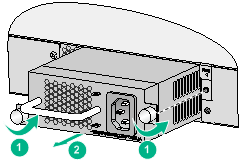
Appearance
Figure 1 Appearance
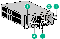
|
(1) Captive screws |
(2) Power receptacle |
|
(3) Bail latch |
(4) Power module handle |
Installing and removing the power module
Safety precautions
To avoid possible bodily injury and power module and device damage, follow these safety precautions:
· When you install and remove the power module, always wear an ESD wrist strap and make sure it makes good skin contact and is reliably grounded.
· Before you install the power module, make sure the voltage of the power source is as required by the power module, and the output voltage of the power module is as required by the device.
· Do not touch any cables or terminals of the power module.
· Do not place the power module in a wet area, and prevent liquid from flowing into the power module.
· To avoid power module damage, do not open the power module. When the internal circuits or components of the power module fail, contact H3C Support.
Tools
Prepare an ESD wrist strap, a flat-blade screwdriver, and a Phillips screwdriver yourself.
Installing and removing the power module
Make sure the power module model is compatible with the device. For more information about hardware compatibility, see the installation guide for the device.
Installing the power module
To avoid bodily injury or device damage, follow the procedure in Figure 2 to install the power module.
Figure 2 Installation procedure
![]()
To install the power module:
1. Wear an ESD wrist strap and make sure the strap makes good skin contact and is reliably grounded.
2. Unpack the power module and verify that the power module model is as required.
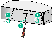
3. Remove the filler panel, if any, from the target power module slot as follows:
a. Loosen the screws on the filler panel with a Phillips screwdriver until the screws are disengaged from the device.
b. Insert a flat-blade screwdriver through the handle on the filler panel and pull the filler panel out along the guide rails.
Figure 3 Removing a filler panel
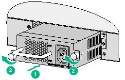
4. Insert the power module into the slot, as shown in Figure 5:
a. Correctly orient the power module with the characters upward.
b. Holding the power module handle with one hand and supporting the power module bottom with the other, slide the power module along the guide rails into the slot.
5. Fasten the captive screws with a Phillips screwdriver to secure the power module to the chassis.
Figure 4 Installing the power module
|
|
NOTE: · Keep the filler panel and the packaging box and packaging bag of the power module for future use. · To prevent damage to the power module or the connector on the backplane of the powered device, insert the power module gently. If you encounter a hard resistance while inserting the power module, pull out the power module and then insert it again. · If the captive screw cannot be tightly fastened, examine the installation of the power module. |
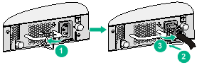
Connecting the power cord
|
|
WARNING! · Make sure the power cord has a separate circuit breaker. · Turn off the circuit breaker before connecting the power cord. |
1. Pull the bail latch to the left side.
2. As shown in Figure 5, plug the female connector end of the power cord into the power receptacle on the power module.
3. Pull the bail latch to the right side to secure the plug to the power receptacle.
4. Connect the other end of the power cord to the power source, and turn on the circuit breaker.
Figure 5 Connecting the power cord
Removing the power module
To avoid bodily injury or device damage, follow the procedure in Figure 6 to remove the power module.
![]()
To remove the power module:
1. Wear an ESD wrist strap and make sure the strap makes good skin contact and is reliably grounded.
2. Turn off the circuit breaker at the power input end.
3. Loosen the captive screws on the power module with a Phillips screwdriver until the captive screws are disengaged from the powered device.
4. Holding the power module handle with one hand and supporting the power module bottom with the other, pull the power module slowly out of the slot along the guide rails.
Figure 7 Removing the power module
5. Put the removed power module on an antistatic mat or into its package.
6. If you are not to insert a power module into the empty slot, insert the filler panel into the slot to prevent dust from entering the chassis.
Copyright © 2016-2018 New H3C Technologies Co., Ltd.
