- Released At: 29-10-2024
- Page Views:
- Downloads:
- Table of Contents
- Related Documents
-
Zero Packet Loss Technical Topics
Copyright © 2024 New H3C Technologies Co., Ltd. All rights reserved.
No part of this manual may be reproduced or transmitted in any form or by any means without prior written consent of New H3C Technologies Co., Ltd.
Except for the trademarks of New H3C Technologies Co., Ltd., any trademarks that may be mentioned in this document are the property of their respective owners.
This guide describes only the most common information for lightning protection. Some information might not be applicable to your products.
Overview
Introduction
Packet loss in network communication affects the integrity and accuracy of data transmission. Common causes for packet loss include network congestion, transmission device failure, network latency, and link failure. Zero packet loss technology uses various methods to ensure network transmission quality, maintaining high availability and integrity of data within the network.
Technical background
As the Internet rapidly develops, more applications demand higher network stability and reliability, especially in fields requiring precise data transmission, such as financial transactions, medical image transfers, and remote education. In these fields, packet loss severely impacts the integrity and accuracy of data, making zero packet loss technology crucial for network stability and reliability.
To achieve zero packet loss, developers of network devices and protocols continuously innovate and improve technology. They achieve zero packet loss by enhancing device processing capabilities, and developing traffic control, congestion control, link backup, route backup, and SRv6 egress protection technologies. In scenarios that require high network transmission reliability, zero packet loss technology is becoming increasingly crucial.
Benefits
Zero packet loss delivers the following benefits:
· Reduces traffic forwarding failure to enhance network reliability.
· Supports multi-dimensional, multi-method zero packet loss to meet the zero packet loss requirements of different network environments.
Application scenarios
Using Layer 2 or Layer 3 link-aggregation traffic redirection to achieve zero packet loss for aggregate traffic
Feature overview
About this feature
Configure a Layer 2 or Layer 3 dynamic link aggregation group on multiple links between devices, and enable traffic redirection on both ends of the aggregate link to achieve uninterrupted traffic on the aggregate link.
Operating mechanism
When link-aggregation traffic redirection is enabled on both ends, traffic on a Selected port will be redirected to the remaining available Selected ports of the aggregation group if one of the following events occurs:
· The port is shut down by using the shutdown command.
· The slot that hosts the port reboots, and the aggregation group spans multiple slots.
· A link in the dynamic aggregation group fails.
Zero packet loss is guaranteed for known unicast packets but not for the other packets.
Figure 1 Traffic forwarded correctly when no link fails
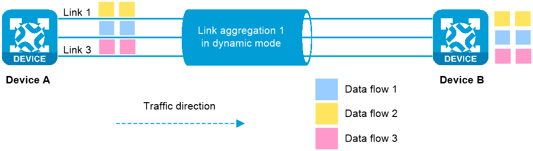
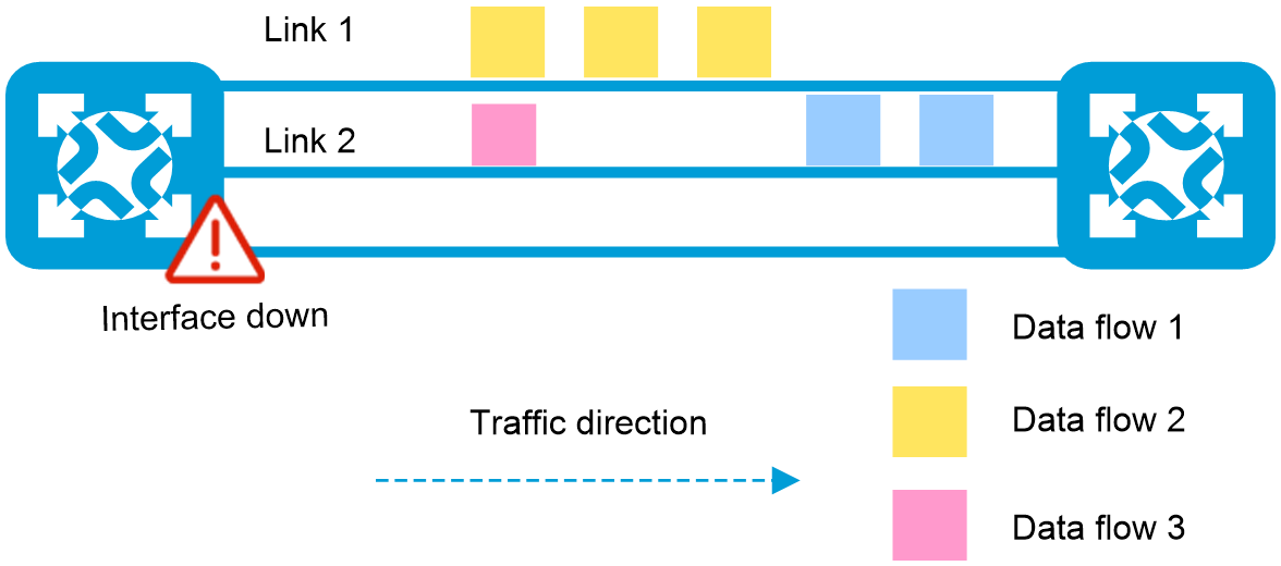
Figure 2 A link fails without link-aggregation traffic redirection configured

Figure 3 A link fails with link-aggregation traffic redirection configured

Restrictions and guidelines
Enable link-aggregation traffic redirection on both ends of an aggregate link to achieve uninterrupted traffic on the aggregate link. Whether link-aggregation traffic redirection is enabled globally and for all aggregate interfaces by default varies by device model.
If you enable both link-aggregation traffic redirection and the spanning tree feature, packet loss might occur when a slot is restarted. As a best practice, do not enable both features.
Link-aggregation traffic redirection cannot operate correctly on an edge aggregate interface.
Only dynamic aggregation groups support link-aggregation traffic redirection.
As a best practice, preferentially enable link-aggregation traffic redirection on the aggregate interfaces. When you enable link-aggregation traffic redirection globally, it might affect the normal communication of aggregation groups if some aggregate interfaces are connected to third-party devices.
After the link-aggregation lacp traffic-redirect-notification enable command is executed, the device will add a proprietary field to the end of the LACP packets. Because the peer device cannot verify this proprietary field, LACP packets might fail to be verified and exchanged. As a result, the aggregation member ports cannot become Selected. To prevent this issue, you must disable link-aggregation traffic redirection on the H3C device when the H3C device connects to a third-party device.
Feature control commands
The following table shows the control commands for link-aggregation traffic redirection. A command executed in the system view takes effect on all aggregation groups on the device. A command executed in aggregate interface view takes effect only on the current aggregation group.
|
Task |
Command |
|
Enable link-aggregation traffic redirection globally. |
link-aggregation lacp traffic-redirect-notification enable (system view) |
|
Enable link-aggregation traffic redirection on an aggregate interface |
link-aggregation lacp traffic-redirect-notification enable (Layer 2/Layer 3 aggregate interface view) |
Application scenarios
Example: Configuring zero packet loss for a Layer 2 dynamic aggregation group
Network configuration
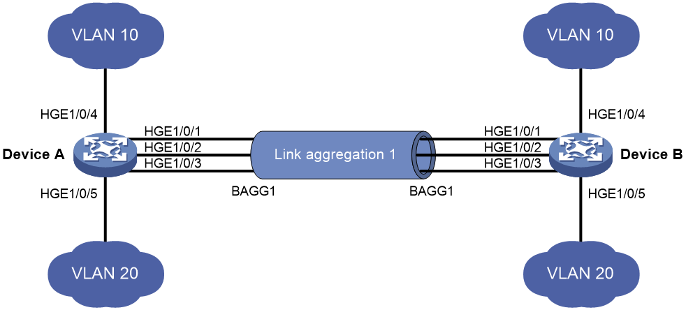
Configure a Layer 2 dynamic aggregation group on multiple links between devices and enable link-aggregation traffic redirection on both ends of the aggregate link. When a link in the aggregation group fails, the system can redirect the traffic from the corresponding port to the other Selected ports, ensuring uninterrupted traffic on the aggregate link.
Figure 4 Network diagram
Major configuration steps
1. Configure VLAN interfaces. (Details not shown.)
2. Configure link-aggregation traffic redirection for a Layer 2 dynamic aggregation group on Device A:
# Create Layer 2 aggregate interface Bridge-Aggregation 1 and configure the interface to operate in dynamic mode. Enable link-aggregation traffic redirection on the aggregate interface.
[DeviceA] interface bridge-aggregation 1
[DeviceA-Bridge-Aggregation1] link-aggregation mode dynamic
[DeviceA-Bridge-Aggregation1] link-aggregation lacp traffic-redirect-notification enable
[DeviceA-Bridge-Aggregation1] quit
# Assign HundredGigE 1/0/1 through HundredGigE 1/0/3 to aggregation group 1.
[DeviceA] interface hundredgige 1/0/1
[DeviceA-HundredGigE1/0/1] port link-aggregation group 1
[DeviceA-HundredGigE1/0/1] quit
[DeviceA] interface hundredgige 1/0/2
[DeviceA-HundredGigE1/0/2] port link-aggregation group 1
[DeviceA-HundredGigE1/0/2] quit
[DeviceA] interface hundredgige 1/0/3
[DeviceA-HundredGigE1/0/3] port link-aggregation group 1
[DeviceA-HundredGigE1/0/3] quit
# Set the link type of Bridge-Aggregation 1 to trunk, and assign it to VLANs 10 and 20.
[DeviceA] interface bridge-aggregation 1
[DeviceA-Bridge-Aggregation1] port link-type trunk
[DeviceA-Bridge-Aggregation1] port trunk permit vlan 10 20
[DeviceA-Bridge-Aggregation1] quit
3. Configuring Device B.
Configure Device B in the same way Device A is configured. (Details not shown.)
4. Configure VLAN interfaces and IP addresses.
If only Layer 2 devices exist in the network, skip this step.
If Layer 3 devices exist in the network and a Layer 2 aggregate interface needs to forward traffic, modify the PVID for the Layer 2 aggregate interface and configure the IP address for the VLAN interface of the PVID. When Layer 3 packets are forwarded through an aggregate link, they are load-shared on that link.
# Configure a VLAN interface and assign the Layer 2 aggregate interface to the corresponding VLAN.
[DeviceA] interface bridge-aggregation 1
[DeviceA-Bridge-Aggregation1] port trunk pvid vlan 100
[DeviceA-Bridge-Aggregation1] quit
[DeviceA] vlan 100
[DeviceA-vlan100] quit
[DeviceA] interface vlan-interface 100
[DeviceA-Vlan-interface200] ip-address 2.2.2.2 24
# Configure routes.
Configure routes on Device A and Device B. (Details not shown.)
¡ If you configure a static route, specify the outgoing interface of the route as the VLAN interface where the Layer 2 aggregate interface resides.
¡ If you configure a dynamic route, configure the VLAN interface where the Layer 2 aggregate interface resides to establish a neighbor.
After configuration, Layer 2 and Layer 3 packets between Device A and Device B will be forwarded through the aggregate interface, and the packets will be load-shared across multiple member links of the aggregate link.
Displaying the configuration
1. Display the configuration.
# On Device A, display detailed information about the aggregation groups.
[DeviceA] display link-aggregation verbose
Loadsharing Type: Shar -- Loadsharing, NonS -- Non-Loadsharing
Port Status: S -- Selected, U -- Unselected, I -- Individual
Port: A -- Auto port, M -- Management port, R -- Reference port
Flags: A -- LACP_Activity, B -- LACP_Timeout, C -- Aggregation,
D -- Synchronization, E -- Collecting, F -- Distributing,
G -- Defaulted, H -- Expired
Aggregate Interface: Bridge-Aggregation1
Creation Mode: Manual
Aggregation Mode: Dynamic
Loadsharing Type: Shar
Management VLANs: None
System ID: 0x8000, 000f-e267-6c6a
Local:
Port Status Priority Index Oper-Key Flag
HGE1/0/1(R) S 32768 11 1 {ACDEF}
HGE1/0/2 S 32768 12 1 {ACDEF}
HGE1/0/3 S 32768 13 1 {ACDEF}
Remote:
Actor Priority Index Oper-Key SystemID Flag
HGE1/0/1 32768 81 1 0x8000, 000f-e267-57ad {ACDEF}
HGE1/0/2 32768 82 1 0x8000, 000f-e267-57ad {ACDEF}
HGE1/0/3 32768 83 1 0x8000, 000f-e267-57ad {ACDEF}
The output shows that aggregation group 1 is a load-sharing Layer 2 dynamic aggregation group containing three Selected ports.
Verifying the configuration (zero packet loss during traffic switchover upon aggregation member port failure)
1. When a Selected member port in the aggregation group fails (three Selected member ports change to two), verify that traffic switchover occurs with zero packet loss.
# After interface HGE 1/0/1 fails, display the packet receiving rate statistics of the interfaces.
<DeviceA> display counters rate inbound interface
Usage: Bandwidth utilization in percentage
Interface Usage (%) Total (pps) Broadcast (pps) Multicast (pps)
BAGG1 1 8445651 -- --
HGE1/0/1 0 0 -- --
HGE1/0/2 1 4222825 -- --
HGE1/0/3 1 4222826 -- --
Overflow: More than 14 digits.
--: Not supported.
# After interface HGE 1/0/1 recovers, display the packet receiving rate statistics of the interfaces and verify that the traffic has switched back to HGE 1/0/1.
<DeviceA> display counters rate inbound interface
Usage: Bandwidth utilization in percentage
Interface Usage (%) Total (pps) Broadcast (pps) Multicast (pps)
BAGG1 1 84445651 -- --
HGE1/0/1 1 28148550 -- --
HGE1/0/2 1 28148551 -- --
HGE1/0/3 1 28148550 -- --
Overflow: More than 14 digits.
--: Not supported.
2. When only one Selected member port in the aggregation group is operating correctly and the others fail (three Selected member ports change to one), verify that traffic switchover occurs with zero packet loss.
# After interfaces HGE 1/0/1 and HGE 1/0/2 fail, display the packet receiving rate statistics of the interfaces. Verify that traffic has switched to HGE 1/0/3 with zero packet loss.
<DeviceA> display counters rate inbound interface
Usage: Bandwidth utilization in percentage
Interface Usage (%) Total (pps) Broadcast (pps) Multicast (pps)
BAGG1 1 1327644 -- --
HGE1/0/1 0 0 -- --
HGE1/0/2 0 0 -- --
HGE1/0/3 1 1327644 -- --
Overflow: More than 14 digits.
--: Not supported.
# After interfaces HGE 1/0/1 and HGE 1/0/2 recover, display the packet receiving rate statistics of the interfaces. Verify that traffic has switched back to HGE 1/0/1 and HGE 1/0/2 with zero packet loss.
<DeviceA> display counters rate inbound interface
Usage: Bandwidth utilization in percentage
Interface Usage (%) Total (pps) Broadcast (pps) Multicast (pps)
BAGG1 1 1327644 -- --
HGE1/0/1 1 442548 -- --
HGE1/0/2 1 442546 -- --
HGE1/0/3 1 442550 -- --
Overflow: More than 14 digits.
--: Not supported.
Test result
Use this scenario to achieve Layer 2 aggregation with zero packet loss. Three interfaces form a Layer 2 aggregate interface. If one or two interfaces fail, traffic will switch to the remaining interfaces with zero packet loss.
Example: Configuring zero packet loss for Layer 3 dynamic aggregation groups
Network configuration
Configure a Layer 3 dynamic aggregation group on multiple links between devices and enable link-aggregation traffic redirection on both ends of the aggregate link. When a link in the aggregation group fails, the system can redirect the traffic from the corresponding port to the other Selected ports, ensuring uninterrupted traffic on the aggregate link.
Figure 5 Network diagram

Major configuration steps
1. Configure link-aggregation traffic redirection for a Layer 3 dynamic aggregation group on Device A:
# Create Layer 3 aggregate interface Route-Aggregation 1, set the link aggregation mode to dynamic, and then assign an IP address and subnet mask to the interface.
<DeviceA> system-view
[DeviceA] interface route-aggregation 1
[DeviceA-Route-Aggregation1] link-aggregation mode dynamic
[DeviceA-Route-Aggregation1] link-aggregation lacp traffic-redirect-notification enable
[DeviceA-Route-Aggregation1] ip address 192.168.1.1 24
[DeviceA-Route-Aggregation1] quit
# Assign HundredGigE 1/0/1 through HundredGigE 1/0/3 to aggregation group 1.
[DeviceA] interface hundredgige 1/0/1
[DeviceA-HundredGigE1/0/1] port link-aggregation group 1
[DeviceA-HundredGigE1/0/1] quit
[DeviceA] interface hundredgige 1/0/2
[DeviceA-HundredGigE1/0/2] port link-aggregation group 1
[DeviceA-HundredGigE1/0/2] quit
[DeviceA] interface hundredgige 1/0/3
[DeviceA-HundredGigE1/0/3] port link-aggregation group 1
[DeviceA-HundredGigE1/0/3] quit
2. Configuring Device B.
Configure Device B in the same way Device A is configured. (Details not shown.)
3. Assign an IP address and subnet mask to the Layer 3 aggregate interface. (Details not shown.)
4. If other devices exist in the network, you must configure the interfaces, IP addresses, and routing protocols on each device to achieve Layer 3 communication.
¡ When configuring a static route on Device A, specify the Layer 3 aggregate interface on Device B as the outgoing interface of the route.
¡ For dynamic routing protocols, establish a neighbor by using the Layer 3 aggregate interface address.
Then, Layer 3 packets between Device A and Device B will be forwarded through the aggregate interface, and the packets will be load-shared across multiple member links of the Layer 3 aggregate link.
Displaying the configuration
# On Device A, display detailed information about the aggregation groups.
[DeviceA] display link-aggregation verbose
Loadsharing Type: Shar -- Loadsharing, NonS -- Non-Loadsharing
Port Status: S -- Selected, U -- Unselected, I -- Individual
Port: A -- Auto port, M -- Management port, R -- Reference port
Flags: A -- LACP_Activity, B -- LACP_Timeout, C -- Aggregation,
D -- Synchronization, E -- Collecting, F -- Distributing,
G -- Defaulted, H -- Expired
Aggregate Interface: Route-Aggregation1
Creation Mode: Manual
Aggregation Mode: Dynamic
Loadsharing Type: Shar
Management VLANs: None
System ID: 0x8000, 000f-e267-6c6a
Local:
Port Status Priority Index Oper-Key Flag
HGE1/0/1(R) S 32768 11 1 {ACDEF}
HGE1/0/2 S 32768 12 1 {ACDEF}
HGE1/0/3 S 32768 13 1 {ACDEF}
Remote:
Actor Priority Index Oper-Key SystemID Flag
HGE1/0/1 32768 81 1 0x8000, 000f-e267-57ad {ACDEF}
HGE1/0/2 32768 82 1 0x8000, 000f-e267-57ad {ACDEF}
HGE1/0/3 32768 83 1 0x8000, 000f-e267-57ad {ACDEF}
The output shows that aggregation group 1 is a load-sharing Layer 3 dynamic aggregation group containing three Selected ports.
Scenario 1 (three Selected member ports change to two): Traffic switchover with zero packet loss upon the failure of a Selected member port in the aggregation group
# After interface HGE 1/0/1 fails, display the packet receiving rate statistics of the interfaces.
<DeviceA> display counters rate inbound interface
Usage: Bandwidth utilization in percentage
Interface Usage (%) Total (pps) Broadcast (pps) Multicast (pps)
HGE1/0/1 0 0 -- --
HGE1/0/2 1 1206646 -- --
HGE1/0/3 1 1206978 -- --
RAGG1 1 2413624 -- --
Overflow: More than 14 digits.
--: Not supported.
# After HGE 1/0/1 recovers, display the packet receiving rate statistics of the interfaces and verify that the traffic has switched back to HGE 1/0/1.
<DeviceA> display counters rate inbound interface
Usage: Bandwidth utilization in percentage
Interface Usage (%) Total (pps) Broadcast (pps) Multicast (pps)
HGE1/0/1 1 804541 -- --
HGE1/0/2 1 804542 -- --
HGE1/0/3 1 804541 -- --
RAGG1 1 2413624 -- --
Overflow: More than 14 digits.
--: Not supported.
Scenario 2 (three Selected member ports change to one): Traffic switchover with zero packet loss when only one interface in the aggregation group is operating correctly and the others fail
# After interfaces HGE 1/0/1 and HGE 1/0/2 fail, display the packet receiving rate statistics of the interfaces. Verify that traffic has switched to HGE 1/0/3 with zero packet loss.
<DeviceA> display counters rate inbound interface
Usage: Bandwidth utilization in percentage
Interface Usage (%) Total (pps) Broadcast (pps) Multicast (pps)
HGE1/0/1 0 0 -- --
HGE1/0/2 1 0 -- --
HGE1/0/3 1 2413624 -- --
RAGG1 1 2413624 -- --
Overflow: More than 14 digits.
--: Not supported.
# After interfaces HGE 1/0/1 and HGE 1/0/2 recover, display the packet receiving rate statistics of the interfaces. Verify that traffic has switched back to HGE 1/0/1 and HGE 1/0/2 with zero packet loss.
<DeviceA> display counters rate inbound interface
Usage: Bandwidth utilization in percentage
Interface Usage (%) Total (pps) Broadcast (pps) Multicast (pps)
HGE1/0/1 1 804541 -- --
HGE1/0/2 1 804542 -- --
HGE1/0/3 1 804541 -- --
RAGG1 1 2413624 -- --
Overflow: More than 14 digits.
--: Not supported.
Test result
Use this scenario to achieve Layer 3 aggregation with zero packet loss. Three interfaces form a Layer 3 aggregate interface. If one or two interfaces fail, traffic will switch to the remaining interfaces with zero packet loss.
Example: Configuring zero packet loss during card restart (aggregation group members located on multiple cards)
Network configuration
Multiple links exist between two devices and these links are located on several cards of Device B. To prevent link failure on Device B caused by card restart or card failure, aggregate multiple links between Device A and Device B into a single dynamic aggregation group, and enable traffic redirection for this group.
If you restart a card on Device B, Device A will switch the traffic destined for that card to other cards, with zero packet loss during the switchover process.
Figure 6 Network diagram

Major configuration steps
Configure a Layer 2 or Layer 3 dynamic aggregation group based on actual conditions. Add interfaces from different interface cards to the same dynamic aggregation group, and configure traffic redirection. For the specific configuration procedures, see the zero packet loss configuration examples for Layer 2 and Layer 3 dynamic aggregation groups.
Zero packet loss technology in IGP/BGP routing
Graceful restart
Feature overview
About this feature
Graceful Restart (GR) ensures forwarding continuity when a protocol restarts or an active/standby switchover occurs. Currently, it is supported by multiple protocols such as RIP, RIPng, OSPF, OSPFv3, IS-IS, BGP, and LDP.
Take OSPF as an example. Without the GR feature enabled, if the OSPF protocol restarts or an active/standby switchover occurs, the device will re-establish OSPF neighbor relationships with neighboring routers, synchronize all route data, and recalculate routes. In this situation, network flapping will occur and traffic forwarding will be interrupted. After the GR feature is enabled, during an OSPF restart or active/standby switchover, surrounding devices can retain their neighbor relationships with the device, keeping the routes and the FIB unchanged. After the device restarts, surrounding devices can help the device complete route synchronization for fast route restoration. With this mechanism, GR ensures network topology stability and achieves zero packet loss.
Operating mechanism
The following roles are required to complete a GR process:
· GR restarter—Graceful restarting router. It must have GR capability.
· GR helper—A neighbor of the GR restarter. It helps the GR restarter to complete the GR process. The GR helper must also be GR-capable.
A device can act as either a GR restarter or a GR helper. The GR role of a device is determined by its function during the GR process.
Figure 7 BGP operating mechanism

The detailed workflow is as follows:
1. GR is enabled on both the local device and the neighboring device.
2. When an active/standby switchover or protocol restart occurs, the GR restarter informs the GR helper of this event.
3. During the GR process, the GR restarter keeps its Routing Information Base (RIB) and Forwarding Information Base (FIB) unchanged. It still uses original routes for packet forwarding, retaining its neighbor relationship with the GR helper.
4. After the active/standby switchover or protocol restart completes, the GR restarter re-establishes a neighbor relationship with the GR helper. The GR restarter then exchanges routing information with the GR helper for routing information restoration.
5. After completing the GR process, the GR restarter actively notifies the GR helper to exit the GR process. When the GR timer expires, both the GR restarter and the GR helper exit the GR process.
6. After the local device restores to the expected state, it continues to learn routing information and maintain its routing table.
Feature control commands
The following table shows the control commands for GR. To enable GR for a routing protocol, execute the related command in the view of that routing protocol.
|
Task |
Command |
|
Enable GR for RIP. |
graceful-restart (RIP view) |
|
Enable GR for RIPng. |
graceful-restart (RIPng view) |
|
Enable GR for OSPF. |
graceful-restart (OSPF view) |
|
Enable GR for OSPFv3. |
graceful-restart (OSPFv3 view) |
|
Enable GR for IS-IS. |
graceful-restart (IS-IS view) |
|
Enable GR for BGP. |
graceful-restart (BGP instance view) |
Example: Configuring GR for OSPF
Network configuration
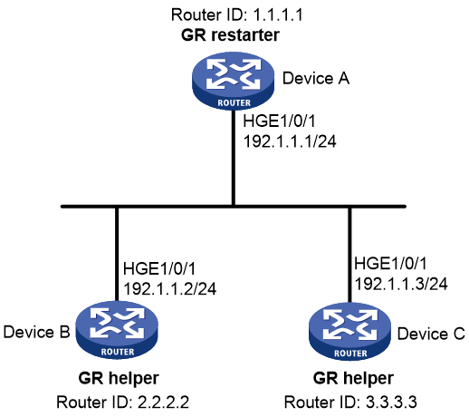
Configure the GR restarter and GR helpers, ensuring zero packet loss when a protocol restart or active/standby switchover occurs on the GR restarter.
· Device A, Device B, and Device C belong to the same autonomous system and the same OSPF routing domain. All of them are GR capable and are connected through OSPF.
· Device A acts as the non-IETF GR restarter. Device B and Device C are the GR helpers, and synchronize their LSDBs with Device A through the out-of-band re-synchronization capability of GR.
Figure 8 Network diagram
Major configuration steps
1. Configure IP addresses for interfaces and configure basic OSPF settings. (Details not shown.)
2. Configure OSPF GR.
# Configure Device A as the non-IETF OSPF GR restarter.
Enable the link-local signaling capability, the out-of-band re-synchronization capability, and non-IETF GR for OSPF process 100.
<DeviceA> system-view
[DeviceA] ospf 100
[DeviceA-ospf-100] enable link-local-signaling
[DeviceA-ospf-100] enable out-of-band-resynchronization
[DeviceA-ospf-100] graceful-restart
[DeviceA-ospf-100] quit
# Configure Device B as the GR helper.
Enable the link-local signaling capability and the out-of-band re-synchronization capability for OSPF process 100.
<DeviceB> system-view
[DeviceB] ospf 100
[DeviceB-ospf-100] graceful-restart helper enable
[DeviceB-ospf-100] enable link-local-signaling
[DeviceB-ospf-100] enable out-of-band-resynchronization
# Configure Device C as the GR helper.
Enable the link-local signaling capability and the out-of-band re-synchronization capability for OSPF process 100.
<DeviceC> system-view
[DeviceC] ospf 100
[DeviceC-ospf-100] graceful-restart helper enable
[DeviceC-ospf-100] enable link-local-signaling
[DeviceC-ospf-100] enable out-of-band-resynchronization
Verifying the configuration
# Enable OSPF GR event debugging and restart the OSPF process by using GR on Device A.
<DeviceA> debugging ospf event graceful-restart
<DeviceA> terminal monitor
<DeviceA> terminal logging level 7
<DeviceA> reset ospf 100 process graceful-restart
Reset OSPF process? [Y/N]:y
%Oct 21 15:29:28:727 2019 DeviceA OSPF/5/OSPF_NBR_CHG: OSPF 100 Neighbor 192.1.1.2(HundredGigE1/0/1) from Full to Down.
%Oct 21 15:29:28:729 2019 DeviceA OSPF/5/OSPF_NBR_CHG: OSPF 100 Neighbor 192.1.1.3(HundredGigE1/0/1) from Full to Down.
*Oct 21 15:29:28:735 2019 DeviceA OSPF/7/DEBUG:
OSPF 100 nonstandard GR Started for OSPF Router
*Oct 21 15:29:28:735 2019 DeviceA OSPF/7/DEBUG:
OSPF 100 created GR wait timer,timeout interval is 40(s).
*Oct 21 15:29:28:735 2019 DeviceA OSPF/7/DEBUG:
OSPF 100 created GR Interval timer,timeout interval is 120(s).
*Oct 21 15:29:28:758 2019 DeviceA OSPF/7/DEBUG:
OSPF 100 created OOB Progress timer for neighbor 192.1.1.3.
*Oct 21 15:29:28:766 2019 DeviceA OSPF/7/DEBUG:
OSPF 100 created OOB Progress timer for neighbor 192.1.1.2.
%Oct 21 15:29:29:902 2019 DeviceA OSPF/5/OSPF_NBR_CHG: OSPF 100 Neighbor 192.1.1.2(HundredGigE1/0/1) from Loading to Full.
*Oct 21 15:29:29:902 2019 DeviceA OSPF/7/DEBUG:
OSPF 100 deleted OOB Progress timer for neighbor 192.1.1.2.
%Oct 21 15:29:30:897 2019 DeviceA OSPF/5/OSPF_NBR_CHG: OSPF 100 Neighbor 192.1.1.3(HundredGigE1/0/1) from Loading to Full.
*Oct 21 15:29:30:897 2019 DeviceA OSPF/7/DEBUG:
OSPF 100 deleted OOB Progress timer for neighbor 192.1.1.3.
*Oct 21 15:29:30:911 2019 DeviceA OSPF/7/DEBUG:
OSPF GR: Process 100 Exit Restart,Reason : DR or BDR change,for neighbor : 192.1.1.3.
*Oct 21 15:29:30:911 2019 DeviceA OSPF/7/DEBUG:
OSPF 100 deleted GR Interval timer.
*Oct 21 15:29:30:912 2019 DeviceA OSPF/7/DEBUG:
OSPF 100 deleted GR wait timer.
%Oct 21 15:29:30:920 2019 DeviceA OSPF/5/OSPF_NBR_CHG: OSPF 100 Neighbor 192.1.1.2(HundredGigE1/0/1) from Full to Down.
%Oct 21 15:29:30:921 2019 DeviceA OSPF/5/OSPF_NBR_CHG: OSPF 100 Neighbor 192.1.1.3(HundredGigE1/0/1) from Full to Down.
%Oct 21 15:29:33:815 2019 DeviceA OSPF/5/OSPF_NBR_CHG: OSPF 100 Neighbor 192.1.1.3(HundredGigE1/0/1) from Loading to Full.
%Oct 21 15:29:35:578 2019 DeviceA OSPF/5/OSPF_NBR_CHG: OSPF 100 Neighbor 192.1.1.2(HundredGigE1/0/1) from Loading to Full.
The output shows that Device A completes GR.
Example: Configuring GR for IS-IS
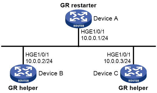
Networking configuration
Configure the GR restarter and GR helpers, ensuring zero packet loss when a protocol restart or active/standby switchover occurs on the GR restarter.
Figure 9 Network diagram
Major configuration steps
1. Configure IP addresses for interfaces and configure basic IS-IS settings. (Details not shown.)
2. Configure IS-IS GR.
Enable IS-IS GR on Device A.
<DeviceA> system-view
[DeviceA] isis 1
[DeviceA-isis-1] graceful-restart
[DeviceA-isis-1] quit
[DeviceA] quit
Verifying the configuration
# Restart the IS-IS process on Device A.
<DeviceA> reset isis all 1 graceful-restart
Reset IS-IS process? [Y/N]:y
# Check the GR state of the IS-IS process on Device A.
<DeviceA> display isis graceful-restart status
Restart information for IS-IS(1)
--------------------------------
Restart status: COMPLETE
Restart phase: Finish
Restart t1: 3, count 10; Restart t2: 60; Restart t3: 300
SA Bit: supported
Level-1 restart information
---------------------------
Total number of interfaces: 1
Number of waiting LSPs: 0
Level-2 restart information
---------------------------
Total number of interfaces: 1
Number of waiting LSPs: 0
Example: Configuring GR for BGP
Network configuration
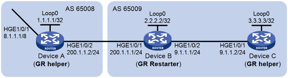
As shown in Figure 10, all devices run BGP. Device A and Device B has an EBGP peer session. Device B and Device C has an IBGP peer session. Configure BGP GR so that the data transmission between Device A and Device C is not affected when an active/standby switchover occurs on Device B.
Major configuration steps
1. Configure Device A.
# Configure IP addresses for interfaces. (Details not shown.)
# Configure an EBGP connection between Device A and Device B.
<DeviceA> system-view
[DeviceA] bgp 65008
[DeviceA-bgp-default] router-id 1.1.1.1
[DeviceA-bgp-default] peer 200.1.1.1 as-number 65009
# Enable BGP GR.
[DeviceA-bgp-default] graceful-restart
# Inject network 8.0.0.0/8 to the IPv4 BGP routing table.
[DeviceA-bgp-default] address-family ipv4
[DeviceA-bgp-default-ipv4] network 8.0.0.0
# Enable Device A to exchange IPv4 unicast routing information with Device B.
[DeviceA-bgp-default-ipv4] peer 200.1.1.1 enable
2. Configure Device B.
# Configure IP addresses for interfaces. (Details not shown.)
# Configure an EBGP connection between Device B and Device A.
<DeviceB> system-view
[DeviceB] bgp 65009
[DeviceB-bgp-default] router-id 2.2.2.2
[DeviceB-bgp-default] peer 200.1.1.2 as-number 65008
# Configure an IBGP connection between Device B and Device C.
[DeviceB-bgp-default] peer 9.1.1.2 as-number 65009
# Enable BGP GR.
[DeviceB-bgp-default] graceful-restart
# Inject networks 200.1.1.0/24 and 9.1.1.0/24 to the IPv4 BGP routing table.
[DeviceB-bgp-default] address-family ipv4
[DeviceB-bgp-default-ipv4] network 200.1.1.0 24
[DeviceB-bgp-default-ipv4] network 9.1.1.0 24
# Enable Device B to exchange IPv4 unicast routing information with Device A and Device C.
[DeviceB-bgp-default-ipv4] peer 200.1.1.2 enable
[DeviceB-bgp-default-ipv4] peer 9.1.1.2 enable
3. Configure Device C.
# Configure IP addresses for interfaces. (Details not shown.)
# Configure an IBGP connection between Device C and Device B.
<DeviceC> system-view
[DeviceC] bgp 65009
[DeviceC-bgp-default] router-id 3.3.3.3
[DeviceC-bgp-default] peer 9.1.1.1 as-number 65009
# Enable BGP GR.
[DeviceC-bgp-default] graceful-restart
# Enable Device C to exchange IPv4 unicast routing information with Device B.
[DeviceC-bgp-default] address-family ipv4
[DeviceC-bgp-default-ipv4] peer 9.1.1.1 enable
Verifying the configuration
Ping Device C on Device A. Meanwhile, trigger an active/standby switchover on Device B. The ping operation is successful throughout the switchover. (Details not shown.)
Nonstop routing
Feature overview
About this feature
Nonstop Routing (NSR) ensures nonstop forwarding services by backing up routing-related information from the active routing protocol process to the standby process. This allows the standby process to seamlessly take over the work of the active process in case of a process failure or active/standby switchover. During NSR configuration, make sure the active and standby processes run on different MPUs or IRF member devices.
Currently, NSR is supported by the RIB (also called routing management) module and multiple protocols such as RIP, RIPng, OSPF, OSPFv3, IS-IS, BGP, and LDP.
Table 1 Differences between NSR and GR
|
Feature |
Advantages |
Disadvantages |
|
Graceful Restart (GR) |
When the system is running correctly, GR consumes fewer system resources than NSR. |
· Neighboring devices require GR configuration. · Data restoration is time consuming upon device recovery. · When multiple nodes fail simultaneously, GR cannot function. |
|
Nonstop Routing (NSR) |
· Loose requirements on neighboring devices: Neighbor nodes do not need to support NSR or be aware of routing information changes. When a protocol process restarts unexpectedly or an active/standby switchover occurs on the local device, the local device does not require support from its neighbors. · Limited impact upon node failure: When the local device fails, the standby process can seamlessly take over the work of the active process without affecting other devices. When multiple nodes fail simultaneously, the system can still operate within control. |
· When the system is running correctly, NSR backs up routing information between the active and standby processes, burdening the system. · To configure NSR on a device, make sure one of the following requirements is met: ¡ The active and standby processes of the related routing protocol must run on different MPUs. To run NSR, make sure the device has a minimum of two MPUs. (Distributed devices.) ¡ The active and standby processes of the related routing protocol must run on different IRF member devices. To run NSR, you must set up an IRF fabric that contains a minimum of two member devices. (Centralized IRF devices.) |
When both GR and NSR are configured for the same routing protocol on a device, the following rules apply:
· NSR has a higher priority than GR. When the active process goes down, the device does not act as the GR restarter and initiates an NSR process to ensure nonstop forwarding.
· The device can act as the GR restarter to initiate a GR process for the routing protocol. If the GR helper performs an active/standby switchover before the GR process finishes, the GR process might fail even if NSR is enabled on the GR helper.
Operating mechanism
Take a distributed device as an example. NSR includes the following phases:
1. Bulk backup: After NSR is enabled, the active MPU backs up routing information and forwarding information in bulk to the standby MPU.
2. Real-time backup: After the bulk backup finishes, the system transitions to the real-time backup phase. Whenever the routing protocol has a change, the change will be backed up from the active MPU to the standby MPU in real time. During this phase, the standby MPU can take the place of the active MPU at any time if needed.
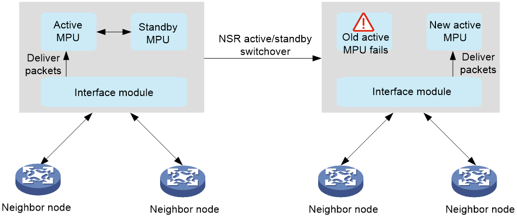
3. Active/standby switchover: When the active MPU fails in NSR real-time backup state, the standby MPU immediately detects the failure through hardware status and becomes active. The interface modules then delivers packets to the new active MPU. The routing protocol does not terminate its neighbor connections, because the whole active/standby switchover finishes within a very short time. Consequently, no traffic loss occurs throughout the switchover.
Figure 11 NSR active/standby switchover
Feature control commands
The following table shows the control commands for NSR. To enable NSR for a routing protocol, execute the related command in the view of that routing protocol.
|
Task |
Command |
|
Enable NSR for RIP. |
non-stop-routing (RIP view) |
|
Enable NSR for RIPng. |
non-stop-routing (RIPng view) |
|
Enable NSR for OSPF. |
non-stop-routing (OSPF view) |
|
Enable NSR for OSPFv3. |
non-stop-routing (OSPFv3 view) |
|
Enable NSR for IS-IS. |
non-stop-routing (IS-IS view) |
|
Enable NSR for BGP. |
non-stop-routing (BGP instance view) |
Example: Configuring NSR for OSPF
Network configuration
NSR is enabled for Device S to ensure forwarding continuity between Device A and Device B when an active/standby switchover occurs on Device S.
Before enabling NSR for Device S, make sure it meets one of the following requirements:
· If Device S is a distributed device, it must have a minimum of two MPUs.
· If Device S is a centralized IRF device, it must be in an IRF fabric containing a minimum of two member devices.
Figure 12 Network diagram

Major configuration steps
1. Configure IP addresses and OSPF settings for interfaces on the devices.
¡ Configure IP addresses and subnet masks for interfaces on the devices according to the above network diagram. The details are not shown.
¡ Configure OSPF on the devices to ensure the following: (Details not shown.)
- Device S, Device A, and Device B can communicate with each other at Layer 3.
- Dynamic route update can be implemented among those devices with OSPF.
2. Configure OSPF NSR.
# Enable OSPF NSR for Device S.
<DeviceS> system-view
[DeviceS] ospf 100
[DeviceS-ospf-100] non-stop-routing
[DeviceS-ospf-100] quit
Verifying the configuration
# Trigger an active/standby switchover on Device S.
[DeviceS] placement reoptimize
Predicted changes to the placement
Predicted changes to the placement
Program Current location New location
---------------------------------------------------------------------
staticroute 0/0 0/0
rib 0/0 0/0
rib6 0/0 0/0
staticroute6 0/0 0/0
ospf 0/0 1/0
Continue? [y/n]:y
Re-optimization of the placement start. You will be notified on completion.
Re-optimization of the placement complete. Use 'display placement' to view the new placement.
# View OSPF neighbors and routes on Device A.
<DeviceA> display ospf peer
OSPF Process 1 with Router ID 2.2.2.1
Neighbor Brief Information
Area: 0.0.0.0
Router ID Address Pri Dead-Time State Interface
3.3.3.1 12.12.12.2 1 37 Full/BDR Vlan100
<DeviceA> display ospf routing
OSPF Process 1 with Router ID 2.2.2.1
Routing Table
Topology base (MTID 0)
Routing for network
Destination Cost Type NextHop AdvRouter Area
44.44.44.44/32 2 Stub 12.12.12.2 4.4.4.1 0.0.0.0
14.14.14.0/24 2 Transit 12.12.12.2 4.4.4.1 0.0.0.0
22.22.22.22/32 0 Stub 22.22.22.22 2.2.2.1 0.0.0.0
12.12.12.0/24 1 Transit 12.12.12.1 2.2.2.1 0.0.0.0
Total nets: 4
Intra area: 4 Inter area: 0 ASE: 0 NSSA: 0
# View OSPF neighbors and routes on Device B.
<DeviceB> display ospf peer
OSPF Process 1 with Router ID 4.4.4.1
Neighbor Brief Information
Area: 0.0.0.0
Router ID Address Pri Dead-Time State Interface
3.3.3.1 14.14.14.2 1 39 Full/BDR Vlan200
<DeviceB> display ospf routing
OSPF Process 1 with Router ID 4.4.4.1
Routing Table
Topology base (MTID 0)
Routing for network
Destination Cost Type NextHop AdvRouter Area
44.44.44.44/32 0 Stub 44.44.44.44 4.4.4.1 0.0.0.0
14.14.14.0/24 1 Transit 14.14.14.1 4.4.4.1 0.0.0.0
22.22.22.22/32 2 Stub 14.14.14.2 2.2.2.1 0.0.0.0
12.12.12.0/24 2 Transit 14.14.14.2 2.2.2.1 0.0.0.0
Total nets: 4
Intra area: 4 Inter area: 0 ASE: 0 NSSA: 0
According to the command outputs, when an active/standby switchover occurs on Device S:
· The neighbor relationships and routing information on Device A and Device B do not change.
· The traffic from Device A to Device B is not impacted.
Test results
In scenarios where an active/standby switchover occurs or the active MPU fails, NSR can retain OSPF neighbors and routing information unchanged, achieving zero packet loss.
Example: Configuring NSR for IS-IS
Networking configuration
NSR is enabled for Device S to ensure forwarding continuity between Device A and Device B when an active/standby switchover occurs on Device S.
Before enabling NSR for Device S, make sure it meets one of the following requirements:
· If Device S is a distributed device, it must have a minimum of two MPUs.
· If Device S is a centralized IRF device, it must be in an IRF fabric containing a minimum of two member devices.
Figure 13 Network diagram

Major configuration steps
1. Configure IP addresses and IS-IS settings for interfaces on the devices.
¡ Configure IP addresses and subnet masks for interfaces on the devices according to the above network diagram. The details are not shown.
¡ Configure IS-IS on the devices to ensure the following: (Details not shown.)
- Device S, Device A, and Device B can communicate with each other at Layer 3.
- Dynamic route update can be implemented among those devices with IS-IS.
2. Configure IS-IS NSR.
# Enable IS-IS NSR for Device S.
<DeviceS> system-view
[DeviceS] isis 1
[DeviceS-isis-1] non-stop-routing
[DeviceS-isis-1] quit
Verifying the configuration
# Trigger an active/standby switchover on Device S.
[DeviceS] placement reoptimize
Predicted changes to the placement
Program Current location New location
---------------------------------------------------------------------
staticroute 0/0 0/0
rib 0/0 0/0
rib6 0/0 0/0
staticroute6 0/0 0/0
isis 0/0 1/0
Continue? [y/n]:y
Re-optimization of the placement start. You will be notified on completion.
Re-optimization of the placement complete. Use 'display placement' to view the new placement.
# View IS-IS neighbors and routes on Device A.
<DeviceA> display isis peer
Peer information for IS-IS(1)
----------------------------
System ID: 0000.0000.0001
Interface: HGE1/0/1 Circuit Id: 0000.0000.0001.01
State: Up HoldTime: 23s Type: L1(L1L2) PRI: 64
System ID: 0000.0000.0001
Interface: HGE1/0/1 Circuit Id: 0000.0000.0001.01
State: Up HoldTime: 28s Type: L2(L1L2) PRI: 64
<DeviceA> display isis route
Route information for IS-IS(1)
-----------------------------
Level-1 IPv4 Forwarding Table
-----------------------------
IPv4 Destination IntCost ExtCost ExitInterface NextHop Flags
-------------------------------------------------------------------------------
12.12.12.0/24 10 NULL HGE1/0/1 Direct D/L/-
22.22.22.22/32 10 NULL Loop0 Direct D/-/-
14.14.14.0/32 10 NULL HGE1/0/1 12.12.12.2 R/L/-
44.44.44.44/32 10 NULL HGE1/0/1 12.12.12.2 R/L/-
Flags: D-Direct, R-Added to Rib, L-Advertised in LSPs, U-Up/Down Bit Set
Level-2 IPv4 Forwarding Table
-----------------------------
IPv4 Destination IntCost ExtCost ExitInterface NextHop Flags
-------------------------------------------------------------------------------
12.12.12.0/24 10 NULL HGE1/0/1 Direct D/L/-
22.22.22.22/32 10 NULL Loop0 Direct D/-/-
14.14.14.0/32 10 NULL
44.44.44.44/32 10 NULL
Flags: D-Direct, R-Added to Rib, L-Advertised in LSPs, U-Up/Down Bit Set
# View IS-IS neighbors and routes on Device B.
<DeviceB> display isis peer
Peer information for IS-IS(1)
----------------------------
System ID: 0000.0000.0001
Interface: HGE1/0/1 Circuit Id: 0000.0000.0001.01
State: Up HoldTime: 23s Type: L1(L1L2) PRI: 64
System ID: 0000.0000.0001
Interface: HGE1/0/1 Circuit Id: 0000.0000.0001.01
State: Up HoldTime: 28s Type: L2(L1L2) PRI: 64
<DeviceB> display isis route
Route information for IS-IS(1)
-----------------------------
Level-1 IPv4 Forwarding Table
-----------------------------
IPv4 Destination IntCost ExtCost ExitInterface NextHop Flags
-------------------------------------------------------------------------------
14.14.14.0/24 10 NULL HGE1/0/1 Direct D/L/-
44.44.44.44/32 10 NULL Loop0 Direct D/-/-
12.12.12.0/32 10 NULL HGE1/0/1 14.14.14.4 R/L/-
22.22.22.22/32 10 NULL HGE1/0/1 14.14.14.4 R/L/-
Flags: D-Direct, R-Added to Rib, L-Advertised in LSPs, U-Up/Down Bit Set
Level-2 IPv4 Forwarding Table
-----------------------------
IPv4 Destination IntCost ExtCost ExitInterface NextHop Flags
-------------------------------------------------------------------------------
14.14.14.0/24 10 NULL HGE1/0/1 Direct D/L/-
44.44.44.44/32 10 NULL Loop0 Direct D/-/-
12.12.12.0/32 10 NULL
22.22.22.22/32 10 NULL
Flags: D-Direct, R-Added to Rib, L-Advertised in LSPs, U-Up/Down Bit Set
The output shows that the neighbor information and routing information on Device A and Device B do not change during the active/standby switchover on Device S. The neighbors (Device A and Device B) are unaware of the switchover.
Test results
In scenarios where an active/standby switchover occurs or the active MPU fails, NSR can retain IS-IS neighbors and routing information unchanged, achieving zero packet loss.
ECMP routes
Feature overview
About ECMP routes
When the next hop of a route becomes unreachable due to a network failure, the routing management and routing protocol of the device will select the optimal route again for packet forwarding, which might interrupt packet forwarding.
By configuring equal-cost multi-path (ECMP) routes, you can enable multiple next hop links to back up each other, minimizing the impact of next hop failures. If the output interface of packets fails, you can achieve zero packet loss. Packets are shared across multiple next hops of ECMP routes. In the current software version, the routing protocols that support load sharing include static routing, IPv6 static routing, RIP, RIPng, OSPF, OSPFv3, IS-IS, IPv6 IS-IS, BGP, and IPv6 BGP.
Operating mechanism
For routes of the same protocol, if multiple optimal routes have the same destination address and cost, these routes form ECMP routes. Packets are shared across multiple next hops in the ECMP routes. Multiple next hops that perform load sharing back up the paths of each other. If one or multiple paths fail, traffic is reassigned among the remaining paths.
· If the path fails because the output interface goes down, the packets will be forwarded through another output interface, achieving zero packet loss. As shown in the figure below, after the local interface goes down, the packets quickly switchover to another path, achieving zero packet loss.
· If the path fails because an intermediate link or the next hop interface fails, few packets might be lost. In this case, you can configure BFD to monitor the next hop link for fast failure detection, achieving zero packet loss.
Figure 14 Packet load sharing
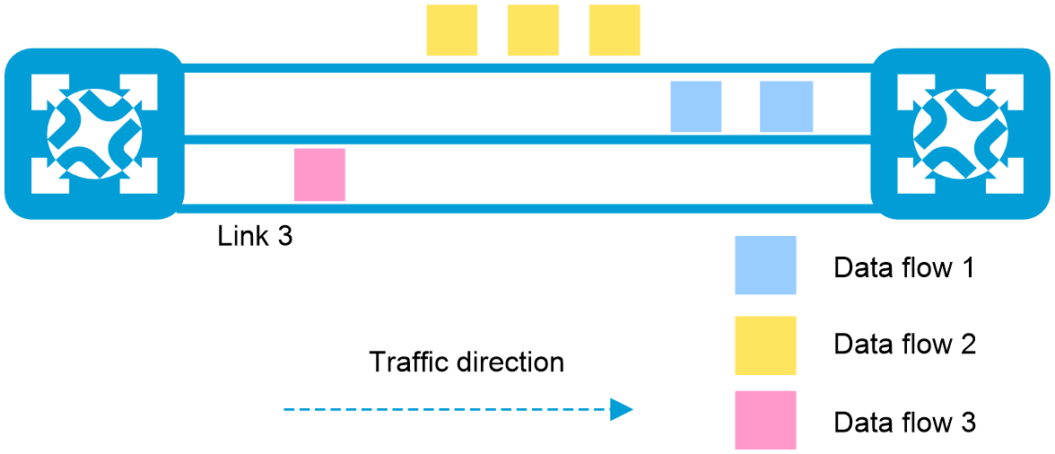
Figure 15 Packet switchover to another path upon local interface failure for zero packet loss
Feature control commands
This feature does not provide control commands. It only requires multiple next hops to the same destination address in the network.
Example: Implementing zero packet loss upon local interface failure of ECMP routes
Network configuration
In an ECMP network, packets are forwarded through load sharing based on a hash value generated from the source IP, destination IP, and protocol number. When the local interface fails or shuts down, the associated next hop in the ECMP path becomes unreachable. At this time, the device does not need to obtain unreachability information from the peer. Instead, it directly notifies the routing table and forwarding table to switch the traffic of the failed next hop to another next hop. This ensures the integrity of network failure processing, enhancing the device stability and reliability.
For example, two equal-cost static routes are available between Device A and Device B. ECMP load sharing is performed for packets destined for IP address 1.2.3.4/24 through Device B. When a link fails, traffic can immediately switch over to another link.
Figure 16 Network diagram

Major configuration steps
1. Configure IP addresses for the interfaces.
2. Configure equal-cost static routes.
# Configure static routes on Device A.
<DeviceA> system-view
[DeviceA] ip route-static 1.2.3.4 24 10.1.1.2 bfd echo-packet
[DeviceA] ip route-static 1.2.3.4 24 20.1.1.2 bfd echo-packet
[DeviceA] quit
Displaying the configuration
1. After configuration, execute the following command to view traffic load sharing across two links.
# Display the packet receiving rate statistics of the interfaces.
<DeviceA> display counters rate outbound interface
Usage: Bandwidth utilization in percentage
Interface Usage (%) Total (pps) Broadcast (pps) Multicast (pps)
HGE1/0/1 2 1174779 -- --
HGE1/0/2 2 1174779 -- --
Overflow: More than 14 digits.
--: Not supported.
Scenario 1: Zero packet loss upon traffic switchover between two physical links
1. After interface HGE 1/0/2 fails, traffic switches over to interface HGE 1/0/1 for forwarding without any packet loss.
# Display the packet receiving rate statistics of the interfaces.
<DeviceA> display counters rate outbound interface
Usage: Bandwidth utilization in percentage
Interface Usage (%) Total (pps) Broadcast (pps) Multicast (pps)
HGE1/0/1 4 2349621 -- --
HGE1/0/2 0 0 -- --
Overflow: More than 14 digits.
--: Not supported.
2. After interface HGE 1/0/2 recovers, traffic is load shared between interfaces HGE 1/0/1 and HGE 1/0/2 without any packet loss.
# Display the packet receiving rate statistics of the interfaces.
<DeviceA> display counters rate outbound interface
Usage: Bandwidth utilization in percentage
Interface Usage (%) Total (pps) Broadcast (pps) Multicast (pps)
HGE1/0/1 2 1174642 -- --
HGE1/0/2 2 1174642 -- --
Overflow: More than 14 digits.
--: Not supported.
Scenario 2: Zero packet loss upon traffic switchover if all subinterfaces of a main Ethernet interface are shut down
1. Create 128 subinterfaces and different subnet IP addresses for HGE 1/0/1 and HGE 1/0/2. Configure a dynamic routing protocol between Device A and Device B to enable load sharing on the subinterfaces.
2. Shut down all subinterfaces of one physical interface. Traffic will switch over to all subinterfaces of another physical interface for load sharing without packet loss. After the shutdown subinterfaces recover, traffic switches to these interfaces for load sharing without any packet loss.
Scenario 3: Zero packet loss upon traffic switchover if half of the subinterfaces of the main Ethernet interface are shut down
1. Create 128 subinterfaces and different subnet IP addresses for HGE 1/0/1 and HGE 1/0/2. Configure a dynamic routing protocol between Device A and Device B to enable load sharing on the subinterfaces.
2. Shut down half of the subinterfaces on each of the two physical interfaces. Traffic will switch over to the remaining available subinterfaces for load sharing without packet loss. After the shutdown subinterfaces recover, traffic switches to these interfaces for load sharing without any packet loss.
Scenario 4: Zero packet loss upon traffic switchback and temporary packet loss upon traffic switchover if a main Ethernet interface is shut down
1. Create 128 subinterfaces and different subnet IP addresses for HGE 1/0/1 and HGE 1/0/2. Configure a dynamic routing protocol between Device A and Device B to enable load sharing on the subinterfaces.
2. Shutting down one main interface will cause traffic on its subinterfaces to switch over to another physical interface and subinterfaces for load sharing. During this process, traffic experiences millisecond-level packet loss. After the main interface recovers, traffic switches to the subinterfaces of the main interface for load sharing without packet loss.
Test result
Shutting down a main Ethernet interface causes a millisecond-level packet loss on the subinterfaces. In the other scenarios, zero packet loss can be achieved upon local interface shutdown of ECMP routes. During a network failure, if one or multiple forwarding paths are available in the ECMP route group, traffic on the failed link will switch over to the remaining available paths.
FRR
Feature overview
About FRR
When a link or network node fails, packets passing through the faulty link or node will be discarded, and data traffic will be disrupted. Upon detecting the failure, the routing protocol must perform the optimal route selection again. For example, failure detection and recovery for IS-IS involves failure detection, LSP update, LSP flooding, route calculation, and forwarding information base (FIB) entry deployment before traffic can switch over to a new link. For services that require high real-time performance, configure the fast reroute (FRR) feature to issue low-priority routes as backup routes to the forwarding table. When a device detects a primary route failure, it immediately uses the backup route to guide packet forwarding, avoiding traffic disruption. If the device can detect the failure promptly enough, it can achieve zero packet loss. As a best practice, use BFD to detect the next hop of the primary route for faster link failure detection and higher network reliability.
Figure 17 FRR
You can configure protocol-specific FRR or inter-protocol FRR as needed. If you configure both features, protocol-specific FRR takes effect. The working mechanism of FRR is as follows:
1. Allow the protocol to automatically select or manually configure the primary and backup next hops based on the actual protocol status.
¡ If only one optimal route is available, you can proceed to the next step.
¡ If multiple equal-cost routes have the same preference and cost, FRR cannot set backup routes for them.
2. Optimal route selection. Inter-protocol FRR preferentially selects routes from the routing information base (RIB). Protocol-specific FRR first selects routes from the protocol, and then issues the optimal routes to the RIB for further selection.
3. RIB issues routes to the FIB. If the RIB determines that a route is the optimal route and the route has a backup next hop, it issues both the primary and backup next hops to the FIB. The primary next hop guides packet forwarding, while the backup next hop is not active.
4. Primary/Backup next hop switchover. When the device detects a failure in the primary next hop, it immediately uses the backup next hop to guide packet forwarding.
5. Route reconvergence. The device performs optimal route selection based on the changed network topology, and uses the new optimal route to guide packet forwarding.
The primary route in FRR requires a backup route with the same destination address. FRR protection cannot take effect if the following conditions exist:
· Inter-protocol FRR cannot find a backup next hop in the RIB.
· Protocol-specific FRR cannot find a backup next hop in the routing table of the protocol.
· Multiple ECMP routes with equal-cost next hops exist.
Inter-protocol FRR
Inter-protocol FRR can specify backup next hops for routes in the RIB. For multiple routes with the same destination address, the next hop of the optimal route is used as the primary next hop, and the next hop of the suboptimal route is used as the backup next hop. The protocols for the optimal and suboptimal routes are different.
Static route FRR
You can specify a backup output interface and backup next hop for static routes, or configure the device to automatically use a suboptimal next hop as a backup next hop.
RIP/RIPng FRR
RIP/RIPng FRR automatically calculates a suboptimal next hop from RIP/RIPng as a backup next hop.
OSPFv3/IPv6 IS-IS FRR
OSPFv3/IPv6 IS-IS FRR can set the backup next hop in the following ways:
· Automatically calculate the backup next hop through the Loop Free Alternate (LFA) algorithm. LFA uses the existing SPF algorithm to complete all calculations and backups locally. The calculation process is relatively simple and does not require expansion of the OSPF/IS-IS protocol.
· You can manually specify a backup next hop for matching routes by using a routing policy.
The LFA algorithm uses a neighbor that can provide a backup link as the root node, and calculates the shortest distance to the destination node by using the Shortest Path First (SPF) algorithm. Then, it calculates a set of backup links with the lowest cost and no loops by using the following LFA inequality: Distance_opt(N,D) < Distance_opt(N,S) + Distance_opt(S,D)
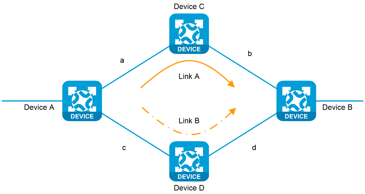
For example, as shown in the figure below, Device A is the source node for traffic forwarding, Device B is the destination node, and Device D is a neighbor that can provide a backup link. The LFA algorithm performs calculation as follows:
1. Selects neighbor node Device D that can provide a backup link, that is, the node of the backup next hop.
2. Uses the SPF algorithm to calculate the shortest path distance d from Device D to the traffic destination node Device B.
3. Calculates the shortest path distance c between backup link node Device D and the source node Device A.
4. Calculates the shortest path distance a + b from traffic source node Device A to traffic destination node Device B.
5. Uses this link as a backup link for FRR if d < a + b + c.
6. Selects the link with the lowest cost if multiple backup links exist.
Figure 18 Backup link calculation with the LFA algorithm
IS-IS/OSPF FRR
IS-IS/OSPF FRR can set the backup next hop in the following ways:
· Use the LFA algorithm to automatically calculate the backup next hop.
· You can manually specify the backup next hop through a routing policy.
· Use remote LFA to automatically calculate the backup next hop.
IS-IS/OSPF supports using remote LFA to automatically calculate the backup next hop. The LFA algorithm selects a backup path only on the local node. For some large-scale networks, especially ring networks, it cannot calculate a backup path and does not meet reliability requirements. The remote LFA algorithm calculates the PQ node across the entire network based on the protected link, and establishes an LDP tunnel between the source node and PQ node for backup next hop protection. When the protected link fails, traffic automatically switches to the backup tunnel path, enhancing network reliability.
Remote LFA typically uses the following concepts:
· P space—Use the source node of the protected link as the root to establish a shortest path tree. All nodes that are reachable from the source node without passing the protected link form the P space. Nodes in the P space are called P nodes.
· Extended P space—Use the source node of the protected link and its neighbors as the roots to establish shortest path trees. All nodes that are reachable from the source node or one of its neighbors without passing the protected link form the extended P space.
· Q space—Use the destination node of the protected link as the root to establish a reverse shortest path tree. All nodes that are reachable from the root node without passing the protected link form the Q space. Nodes in the Q space are called Q nodes.
· PQ node—A PQ node refers to a node that resides in both the extended P space and the Q space. Remote LFA uses a PQ node as the destination node of a protected link.
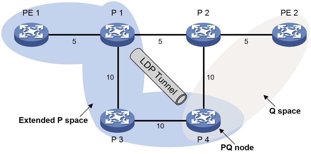
As shown in Figure 19, the traffic forwarding path is PE 1—P 1—P 2—PE 2. To avoid traffic loss caused by link failures between P 1 and P 2, the system establishes an LDP tunnel between P 1 and P 4, which is the PQ node. When the link between P 1 and P 2 fails, P 1 encapsulates IP packets in MPLS packets and sends the MPLS packets to P 4 through the LDP tunnel. After receiving the MPLS packets, P 4 removes the MPLS labels of the packets and then forwards the packets to the next hop based on the IP routing table. This ensures rapid protection and prevents traffic loss.
In Figure 19, the system calculates the PQ node as follows:
1. Uses P 1 (source node of the protected link) and its neighbors except P 2 (which passes the protected link) as the roots to establish shortest path trees.
2. Finds out all nodes that are reachable from P 1 or one of its neighbors without passing the protected link, which are PE 1, P 1, P 3, and P 4.
These nodes form the extended P space.
3. Uses P 2 (destination node of the protected link) as the root to establish a reverse shortest path tree.
4. Finds out all nodes that are reachable from P 2 without passing the protected link, which are PE 2 and P 4.
These nodes form the Q space.
5. Finds out all nodes that reside in both the extended P space and the Q space.
Only P 4 resides in both the extended P space and the Q space, so P 4 is the PQ node of the protected link.
Figure 19 Network diagram for remote LFA
BGP FRR
BGP FRR can set the backup next hop as follows:
· BGP automatically selects a backup route. If the routes to the same destination network are learned from different BGP peers and they have different costs, a primary route and a backup route are generated.
· You can manually specify a backup next hop for matching routes by using a routing policy.
IGP/BGP FRR support for primary and backup next hops in a many-to-one, many-to-many, and one-to-many relationship
In the current software version, IGP/BGP FRR does not support primary and backup next hops in a many-to-many or one-to-many relationship. That is, FRR does not support setting multiple backup next hops for a route. Only one backup next hop is issued to the FIB along with the primary next hop. If multiple low-priority links exist in the network, only the next hop of the highest-priority backup link becomes the backup next hop for FRR.
Except OSPF and IS-IS, other protocols do not support primary and backup next hops in a many-to-one relationship
For OSPF and IS-IS, some devices support multiple primary next hops with a single backup next hop. The devices support selecting shared backup next hop information for ECMP routes through the LFA algorithm. The specific configuration methods are as follows:
· Specify the ecmp-shared keyword when you execute the fast-reroute command in IS-IS IPv4 unicast address family view or IS-IS IPv4 unicast topology view to configure IS-IS FRR.
· Specify the ecmp-shared keyword when you execute the fast-reroute command in OSPF view or OSPF IPv4 unicast topology view to configure OSPF FRR.
After configuration, if a device has ECMP routes and a suboptimal route, the LFA algorithm will specify the suboptimal route as the backup route.
Feature control commands
The following table shows the control commands for FRR.
|
Command |
|
|
Enable IPv4 or IPv6 RIB inter-protocol FRR. |
inter-protocol fast-reroute (RIB IPv4 address family view or RIB IPv6 address family view) |
|
Configure static route FRR to automatically select a backup next hop. |
ip route-static fast-reroute auto (system view) |
|
Configure RIP FRR. |
fast-reroute (RIP view) |
|
Configure RIPng FRR. |
fast-reroute (RIPng view) |
|
Configure OSPF FRR. |
fast-reroute (OSPF view or OSPF IPv4 unicast topology view) |
|
Configure OSPFv3 FRR |
fast-reroute (OSPFv3 view) |
|
Configure IS-IS FRR. |
Fast-reroute (IS-IS IPv4 unicast address family view, IS-IS IPv4 unicast topology view, or IS-IS IPv6 unicast address family view) |
|
Enable BGP FRR for a BGP address family. |
pic (BGP IPv4 unicast address family view, BGP-VPN IPv4 unicast address family view, BGP IPv6 unicast address family view, or BGP-VPN IPv6 unicast address family view) |
|
Apply a routing policy to FRR for a BGP address family. |
· fast-reroute route-policy (BGP IPv4 unicast address family view, BGP-VPN IPv4 unicast address family view, BGP IPv6 unicast address family view, or BGP-VPN IPv6 unicast address family view) · apply [ ipv6 ] fast-reroute backup-nexthop (routing policy node view) |
Example: Configuring IS-IS remote LFA FRR
Network configuration
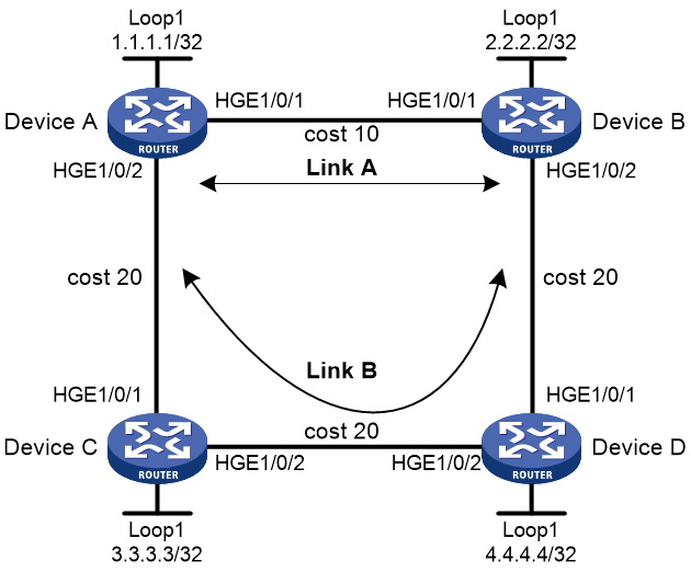
As shown in Figure 20, Device A, Device B, Device C, and Device D reside in the same IS-IS routing domain.
· Run IS-IS on all the routers to interconnect them with each other.
· Configure MPLS LDP on all the devices.
· Configure IS-IS remote LFA FRR so that when Link A fails, traffic can be switched to Link B immediately.
|
Device |
Interface |
IP address |
Device |
Interface |
IP address |
|
Device A |
HGE1/0/1 |
12.12.12.1/24 |
Device B |
HGE1/0/1 |
12.12.12.2/24 |
|
|
HGE1/0/2 |
13.13.13.1/24 |
|
HGE1/0/2 |
15.15.15.1/24 |
|
|
Loop1 |
1.1.1.1/32 |
|
Loop1 |
2.2.2.2/32 |
|
Device C |
HGE1/0/1 |
13.13.13.2/24 |
Device D |
HGE1/0/1 |
15.15.15.2/24 |
|
|
HGE1/0/2 |
14.14.14.1/24 |
|
HGE1/0/2 |
14.14.14.2/24 |
|
|
Loop1 |
3.3.3.3/32 |
|
Loop1 |
4.4.4.4/32 |
Prerequisites
Configure IP addresses for the interfaces on the devices according to the network diagram.
Procedure
1. Configure IS-IS and MPLS LDP on all the devices:
# Configure Device A.
<DeviceA> system-view
[DeviceA] mpls lsr-id 1.1.1.1
[DeviceA] mpls ldp
[DeviceA-ldp] accept target-hello all
[DeviceA-ldp] quit
[DeviceA] isis 1
[DeviceA-isis-1] network-entity 00.0000.0000.0001.00
[DeviceA-isis-1] quit
[DeviceA] interface hundredgige 1/0/1
[DeviceA-HundredGigE1/0/1] isis enable 1
[DeviceA-HundredGigE1/0/1] isis cost 10
[DeviceA-HundredGigE1/0/1] mpls enable
[DeviceA-HundredGigE1/0/1] mpls ldp enable
[DeviceA-HundredGigE1/0/1] quit
[DeviceA] interface hundredgige 1/0/2
[DeviceA-HundredGigE1/0/2] isis enable 1
[DeviceA-HundredGigE1/0/2] isis cost 20
[DeviceA-HundredGigE1/0/2] mpls enable
[DeviceA-HundredGigE1/0/2] mpls ldp enable
[DeviceA-HundredGigE1/0/2] quit
[DeviceA] interface loopback 1
[DeviceA-LoopBack1] isis enable 1
[DeviceA-LoopBack1] quit
# Configure Device B.
<DeviceB> system-view
[DeviceB] mpls lsr-id 2.2.2.2
[DeviceB] mpls ldp
[DeviceB-ldp] accept target-hello all
[DeviceB-ldp] quit
[DeviceB] isis 1
[DeviceB-isis-1] network-entity 00.0000.0000.0002.00
[DeviceB-isis-1] quit
[DeviceB] interface hundredgige 1/0/1
[DeviceB-HundredGigE1/0/1] isis enable 1
[DeviceB-HundredGigE1/0/1] isis cost 10
[DeviceB-HundredGigE1/0/1] mpls enable
[DeviceB-HundredGigE1/0/1] mpls ldp enable
[DeviceB-HundredGigE1/0/1] quit
[DeviceB] interface hundredgige 1/0/2
[DeviceB-HundredGigE1/0/2] isis enable 1
[DeviceB-HundredGigE1/0/2] isis cost 20
[DeviceB-HundredGigE1/0/2] mpls enable
[DeviceB-HundredGigE1/0/2] mpls ldp enable
[DeviceB-HundredGigE1/0/2] quit
[DeviceB] interface loopback 1
[DeviceB-LoopBack1] isis enable 1
[DeviceB-LoopBack1] quit
# Configure Device C.
<DeviceC> system-view
[DeviceC] mpls lsr-id 3.3.3.3
[DeviceC] mpls ldp
[DeviceC-ldp] accept target-hello all
[DeviceC-ldp] quit
[DeviceC] isis 1
[DeviceC-isis-1] network-entity 00.0000.0000.0003.00
[DeviceC-isis-1] quit
[DeviceC] interface hundredgige 1/0/1
[DeviceC-HundredGigE1/0/1] isis enable 1
[DeviceC-HundredGigE1/0/1] isis cost 20
[DeviceC-HundredGigE1/0/1] mpls enable
[DeviceC-HundredGigE1/0/1] mpls ldp enable
[DeviceC-HundredGigE1/0/1] quit
[DeviceC] interface hundredgige 1/0/2
[DeviceC-HundredGigE1/0/2] isis enable 1
[DeviceC-HundredGigE1/0/2] isis cost 20
[DeviceC-HundredGigE1/0/2] mpls enable
[DeviceC-HundredGigE1/0/2] mpls ldp enable
[DeviceC-HundredGigE1/0/2] quit
[DeviceC] interface loopback 1
[DeviceC-LoopBack1] isis enable 1
[DeviceC-LoopBack1] quit
# Configure Device D.
<DeviceD> system-view
[DeviceD] mpls lsr-id 4.4.4.4
[DeviceD] mpls ldp
[DeviceD-ldp] accept target-hello all
[DeviceD-ldp] quit
[DeviceD] isis 1
[DeviceD-isis-1] network-entity 00.0000.0000.0004.00
[DeviceD-isis-1] quit
[DeviceD] interface hundredgige 1/0/1
[DeviceD-HundredGigE1/0/1] isis enable 1
[DeviceD-HundredGigE1/0/1] isis cost 20
[DeviceD-HundredGigE1/0/1] mpls enable
[DeviceD-HundredGigE1/0/1] mpls ldp enable
[DeviceD-HundredGigE1/0/1] quit
[DeviceD] interface hundredgige 1/0/2
[DeviceD-HundredGigE1/0/2] isis enable 1
[DeviceD-HundredGigE1/0/2] isis cost 20
[DeviceD-HundredGigE1/0/2] mpls enable
[DeviceD-HundredGigE1/0/2] mpls ldp enable
[DeviceD-HundredGigE1/0/2] quit
[DeviceD] interface loopback 1
[DeviceD-LoopBack1] isis enable 1
[DeviceD-LoopBack1] quit
2. Configure IS-IS remote LFA FRR:
# Configure Device A.
[DeviceA] isis 1
[DeviceA-isis-1] address-family ipv4
[DeviceA-isis-1-ipv4] fast-reroute lfa
[DeviceA-isis-1-ipv4] fast-reroute remote-lfa tunnel ldp
[DeviceA-isis-1-ipv4] quit
[DeviceA-isis-1] quit
Verifying the configuration
1. Display the configuration:
# Display route 2.2.2.2/32 on Device A to view the backup next hop information.
[DeviceA] display isis route ipv4 2.2.2.2 32 verbose
Route information for IS-IS(1)
------------------------------
Level-1 IPv4 Forwarding Table
-----------------------------
IPv4 Dest : 2.2.2.2/32 Int. Cost : 10 Ext. Cost : NULL
Admin Tag : - Src Count : 1 Flag : R/L/-
InLabel : 4294967295 InLabel Flag: -/-/-/-/-/-
NextHop : Interface : ExitIndex :
12.12.12.2 HGE1/0/1 0x00000002
Nib ID : 0x14000008 OutLabel : 4294967295 OutLabelFlag: -
LabelSrc : N/A Delay Flag : N/A
Remote-LFA:
Interface : HGE1/0/2
BkNextHop : 13.13.13.2 LsIndex : 0x01000002
Tunnel destination address: 4.4.4.4
Backup label: {1149}
Flags: D-Direct, R-Added to Rib, L-Advertised in LSPs, U-Up/Down Bit Set
InLabel flags: R-Readvertisement, N-Node SID, P-no PHP
E-Explicit null, V-Value, L-Local
OutLabelFlags: E-Explicit null, I-Implicit null, N-Nomal, P-SR label prefer
Level-2 IPv4 Forwarding Table
-----------------------------
IPv4 Dest : 2.2.2.2/32 Int. Cost : 10 Ext. Cost : NULL
Admin Tag : - Src Count : 3 Flag : -/-/-
InLabel : 4294967295 InLabel Flag: -/-/-/-/-/-
Flags: D-Direct, R-Added to Rib, L-Advertised in LSPs, U-Up/Down Bit Set
InLabel flags: R-Readvertisement, N-Node SID, P-no PHP
E-Explicit null, V-Value, L-Local
OutLabelFlags: E-Explicit null, I-Implicit null, N-Nomal, P-SR label prefer
2. Verify the configuration after traffic switchover:
# Display traffic for the primary next hop.
[DeviceA] display counters rate outbound interface
Usage: Bandwidth utilization in percentage
Interface Usage (%) Total (pps) Broadcast (pps) Multicast (pps)
HGE1/0/1 6 3905728 -- --
HGE1/0/2 0 0 -- --
Overflow: More than 14 digits.
--: Not supported.
# When the primary output interface HGE 1/0/1 fails, traffic switches over to the backup output interface HGE 1/0/2 with zero packet loss during the process.
[DeviceA] display counters rate outbound interface
Usage: Bandwidth utilization in percentage
Interface Usage (%) Total (pps) Broadcast (pps) Multicast (pps)
HGE1/0/1 0 0 -- --
HGE1/0/2 6 3905728 -- --
Overflow: More than 14 digits.
--: Not supported.
# After the primary output interface HGE 1/0/1 recovers, traffic switches back to HGE 1/0/1 with zero packet loss during the process.
Test result
In this scenario, no packet loss occurs during traffic forwarding through the primary next hop of IS-IS. When the primary next hop fails, traffic can immediately switch to the backup next hop.
Example: Configuring BGP FRR
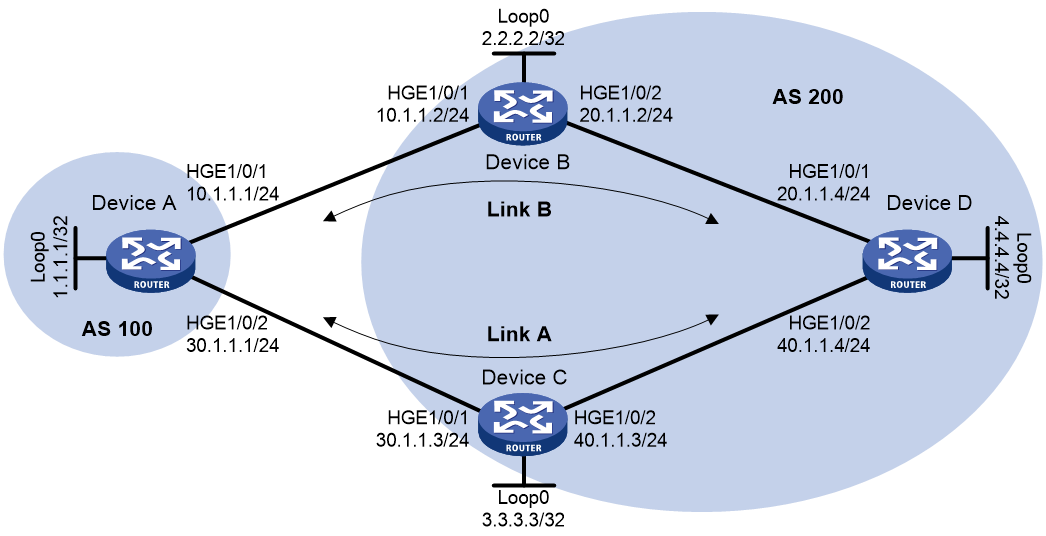
Network configuration
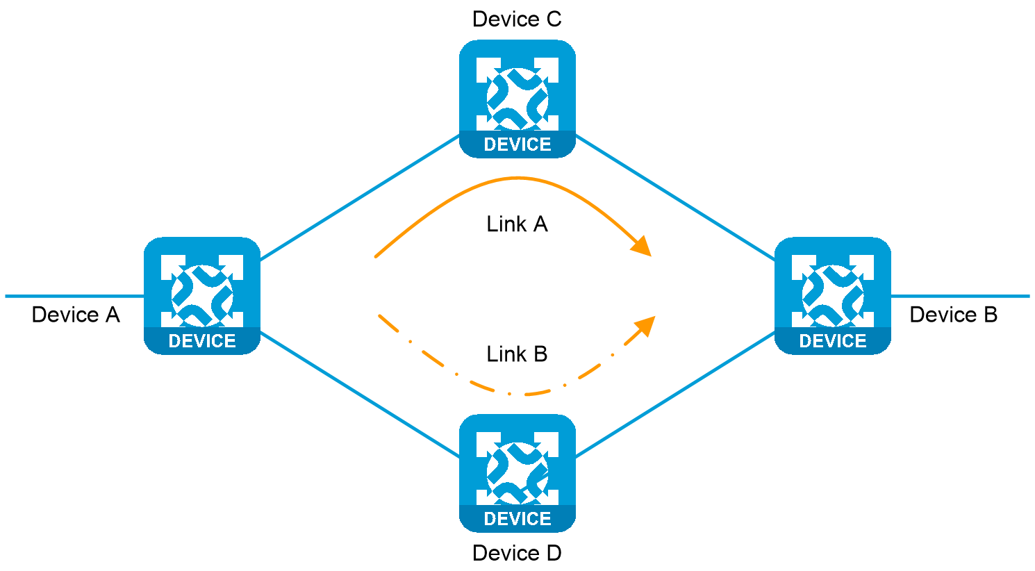
As shown in Figure 21, two links exist between Device A and Device D. To achieve zero packet loss when a link failure occurs, configure BGP FRR and specify link A with lower priority as the backup link. Typically, traffic between Device A and Device D is forwarded through link B. If link B fails, traffic immediately switches over to link A.
Major configuration steps
1. Configure IP addresses for interfaces and configure OSPF settings. (Details not shown.)
2. Configure OSPF in AS 200 to advertise subnet routes associated with the interfaces (including loopback interfaces) and ensure connectivity among Device B, Device C, and Device D. (Details not shown.)
3. Configure BGP connections.
# Configure Device A to establish EBGP sessions to Device B and Device C, and advertise network 1.1.1.1/32.
<DeviceA> system-view
[DeviceA] bgp 100
[DeviceA-bgp-default] router-id 1.1.1.1
[DeviceA-bgp-default] peer 10.1.1.2 as-number 200
[DeviceA-bgp-default] peer 30.1.1.3 as-number 200
[DeviceA-bgp-default] address-family ipv4 unicast
[DeviceA-bgp-default-ipv4] peer 10.1.1.2 enable
[DeviceA-bgp-default-ipv4] peer 30.1.1.3 enable
[DeviceA-bgp-default-ipv4] network 1.1.1.1 32
# Configure Device B to establish an EBGP session to Device A, and an IBGP session to Device D.
<DeviceB> system-view
[DeviceB] bgp 200
[DeviceB-bgp-default] router-id 2.2.2.2
[DeviceB-bgp-default] peer 10.1.1.1 as-number 100
[DeviceB-bgp-default] peer 4.4.4.4 as-number 200
[DeviceB-bgp-default] peer 4.4.4.4 connect-interface loopback 0
[DeviceB-bgp-default] address-family ipv4 unicast
[DeviceB-bgp-default-ipv4] peer 10.1.1.1 enable
[DeviceB-bgp-default-ipv4] peer 4.4.4.4 enable
[DeviceB-bgp-default-ipv4] peer 4.4.4.4 next-hop-local
[DeviceB-bgp-default-ipv4] quit
[DeviceB-bgp-default] quit
# Configure Device C to establish an EBGP session to Device A, and an IBGP session to Device D.
<DeviceC> system-view
[DeviceC] bgp 200
[DeviceC-bgp-default] router-id 3.3.3.3
[DeviceC-bgp-default] peer 30.1.1.1 as-number 100
[DeviceC-bgp-default] peer 4.4.4.4 as-number 200
[DeviceC-bgp-default] peer 4.4.4.4 connect-interface loopback 0
[DeviceC-bgp-default] address-family ipv4 unicast
[DeviceC-bgp-default-ipv4] peer 30.1.1.1 enable
[DeviceC-bgp-default-ipv4] peer 4.4.4.4 enable
[DeviceC-bgp-default-ipv4] peer 4.4.4.4 next-hop-local
[DeviceC-bgp-default-ipv4] quit
[DeviceC-bgp-default] quit
# Configure Device D to establish IBGP sessions to Device B and Device C, and advertise network 4.4.4.4/32.
<DeviceD> system-view
[DeviceD] bgp 200
[DeviceD-bgp-default] router-id 4.4.4.4
[DeviceD-bgp-default] peer 2.2.2.2 as-number 200
[DeviceD-bgp-default] peer 2.2.2.2 connect-interface loopback 0
[DeviceD-bgp-default] peer 3.3.3.3 as-number 200
[DeviceD-bgp-default] peer 3.3.3.3 connect-interface loopback 0
[DeviceD-bgp-default] address-family ipv4 unicast
[DeviceD-bgp-default-ipv4] peer 2.2.2.2 enable
[DeviceD-bgp-default-ipv4] peer 3.3.3.3 enable
[DeviceD-bgp-default-ipv4] network 4.4.4.4 32
4. Configure preferred values so Link B is used to forward traffic between Device A and Device D:
# Configure Device A to set the preferred value to 100 for routes received from Device B.
[DeviceA-bgp-default-ipv4] peer 10.1.1.2 preferred-value 100
[DeviceA-bgp-default-ipv4] quit
[DeviceA-bgp-default] quit
# Configure Device D to set the preferred value to 100 for routes received from Device B.
[DeviceD-bgp-default-ipv4] peer 2.2.2.2 preferred-value 100
[DeviceD-bgp-default-ipv4] quit
[DeviceD-bgp-default] quit
5. Configure BGP FRR:
# On Device A, configure the source address of BFD echo packets as 11.1.1.1.
[DeviceA] bfd echo-source-ip 11.1.1.1
# Create routing policy frr to set a backup next hop 30.1.1.3 (Device C) for the route destined for 4.4.4.4/32.
[DeviceA] ip prefix-list abc index 10 permit 4.4.4.4 32
[DeviceA] route-policy frr permit node 10
[DeviceA-route-policy] if-match ip address prefix-list abc
[DeviceA-route-policy] apply fast-reroute backup-nexthop 30.1.1.3
[DeviceA-route-policy] quit
# Use BFD echo packet mode to detect the connectivity to Device D.
[DeviceA] bgp 100
[DeviceA-bgp-default] primary-path-detect bfd echo
# Apply the routing policy to BGP FRR for BGP IPv4 unicast address family.
[DeviceA-bgp-default] address-family ipv4 unicast
[DeviceA-bgp-default-ipv4] fast-reroute route-policy frr
[DeviceA-bgp-default-ipv4] quit
[witchA-bgp-default] quit
# On Device D, set the source address of BFD echo packets to 44.1.1.1.
[DeviceD] bfd echo-source-ip 44.1.1.1
# Create routing policy frr to set a backup next hop 3.3.3.3 (Device C) for the route destined for 1.1.1.1/32.
[DeviceD] ip prefix-list abc index 10 permit 1.1.1.1 32
[DeviceD] route-policy frr permit node 10
[DeviceD-route-policy] if-match ip address prefix-list abc
[DeviceD-route-policy] apply fast-reroute backup-nexthop 3.3.3.3
[DeviceD-route-policy] quit
# Use BFD echo packet mode to detect the connectivity to Device A.
[DeviceD] bgp 200
[DeviceD-bgp-default] primary-path-detect bfd echo
# Apply the routing policy to BGP FRR for BGP IPv4 unicast address family.
[DeviceD-bgp-default] address-family ipv4 unicast
[DeviceD-bgp-default-ipv4] fast-reroute route-policy frr
[DeviceD-bgp-default-ipv4] quit
[DeviceD-bgp-default] quit
Verifying the configuration
1. Display the configuration:
# Display route 4.4.4.4/32 on Device A to view the backup next hop information.
[DeviceA] display ip routing-table 4.4.4.4 32 verbose
Summary count : 1
Destination: 4.4.4.4/32
Protocol: BGP Process ID: 0
SubProtID: 0x2 Age: 00h01m52s
Cost: 0 Preference: 255
IpPre: N/A QosLocalID: N/A
Tag: 0 State: Active Adv
OrigTblID: 0x0 OrigVrf: default-vrf
TableID: 0x2 OrigAs: 200
NibID: 0x15000003 LastAs: 200
AttrID: 0x5 Neighbor: 10.1.1.2
Flags: 0x10060 OrigNextHop: 10.1.1.2
Label: NULL RealNextHop: 10.1.1.2
BkLabel: NULL BkNextHop: 30.1.1.3
SRLabel: NULL Interface: HundredGigE1/0/1
BkSRLabel: NULL BkInterface: HundredGigE1/0/2
Tunnel ID: Invalid IPInterface: HundredGigE1/0/1
BkTunnel ID: Invalid BKIPInterface: N/A
InLabel: NULL ColorInterface: N/A
SIDIndex: NULL BKColorInterface: N/A
FtnIndex: 0x0 TunnelInterface: N/A
TrafficIndex: N/A BKTunnelInterface: N/A
Connector: N/A PathID: 0x0
SRTunnelID: Invalid
SID Type: N/A NID: Invalid
FlushNID: Invalid BkNID: Invalid
BkFlushNID: Invalid StatFlags: 0x0
Exp: N/A
VpnPeerId: N/A Dscp: N/A
SID: N/A OrigLinkID: 0x0
BkSID: N/A RealLinkID: 0x0
CommBlockLen: 0
# Display route 1.1.1.1/32 on Device D to view the backup next hop information.
[DeviceD] display ip routing-table 1.1.1.1 32 verbose
Summary count : 1
Destination: 1.1.1.1/32
Protocol: BGP Process ID: 0
SubProtID: 0x1 Age: 00h00m36s
Cost: 0 Preference: 255
IpPre: N/A QosLocalID: N/A
Tag: 0 State: Active Adv
OrigTblID: 0x0 OrigVrf: default-vrf
TableID: 0x2 OrigAs: 100
NibID: 0x15000003 LastAs: 100
AttrID: 0x1 Neighbor: 2.2.2.2
Flags: 0x10060 OrigNextHop: 2.2.2.2
Label: NULL RealNextHop: 20.1.1.2
BkLabel: NULL BkNextHop: 40.1.1.3
SRLabel: NULL Interface: HundredGigE1/0/1
BkSRLabel: NULL BkInterface: HundredGigE1/0/2
Tunnel ID: Invalid IPInterface: HundredGigE1/0/1
BkTunnel ID: Invalid BKIPInterface: N/A
InLabel: NULL ColorInterface: N/A
SIDIndex: NULL BKColorInterface: N/A
FtnIndex: 0x0 TunnelInterface: N/A
TrafficIndex: N/A BKTunnelInterface: N/A
Connector: N/A PathID: 0x0
SRTunnelID: Invalid
SID Type: N/A NID: Invalid
FlushNID: Invalid BkNID: Invalid
BkFlushNID: Invalid StatFlags: 0x0
Exp: N/A
VpnPeerId: N/A Dscp: N/A
SID: N/A OrigLinkID: 0x0
BkSID: N/A RealLinkID: 0x0
CommBlockLen: 0
2. Verify the configuration after traffic switchover:
# Typically, Device A sends traffic destined for destination address 4.4.4.4/32 out of interface HGE 1/0/1.
[DeviceA] display counters rate outbound interface
Usage: Bandwidth utilization in percentage
Interface Usage (%) Total (pps) Broadcast (pps) Multicast (pps)
HGE1/0/1 6 3906302 -- --
HGE1/0/2 0 0 -- --
Overflow: More than 14 digits.
--: Not supported.
# When the primary output interface HGE 1/0/1 of Device A fails, traffic immediately switches over to the backup interface HGE 1/0/2, with zero packet loss during this process.
[DeviceA] display counters rate outbound interface
Usage: Bandwidth utilization in percentage
Interface Usage (%) Total (pps) Broadcast (pps) Multicast (pps)
HGE1/0/1 0 0 -- --
HGE1/0/2 6 3906626 -- --
Overflow: More than 14 digits.
--: Not supported.
# When the primary output interface HGE 1/0/1 of Device A recovers, traffic switches back to HGE 1/0/1 with zero packet loss during this process.
[DeviceA] display counters rate outbound interface
Usage: Bandwidth utilization in percentage
Interface Usage (%) Total (pps) Broadcast (pps) Multicast (pps)
HGE1/0/1 6 3906152 -- --
HGE1/0/2 0 0 -- --
Overflow: More than 14 digits.
--: Not supported.
Zero packet loss technology in an EVPN VPWS network
In an EVPN VPWS network, you can achieve zero packet loss by configuring multihomed sites and fast reroute (FRR).
EVPN VPWS multihomed sites
Feature overview
About this feature
EVPN VPWS supports deploying multiple PEs at a site for redundancy and high availability. On the redundant PEs, Ethernet links connected to the site form an ES that is uniquely identified by an ESI. EVPN VPWS supports only dualhoming.
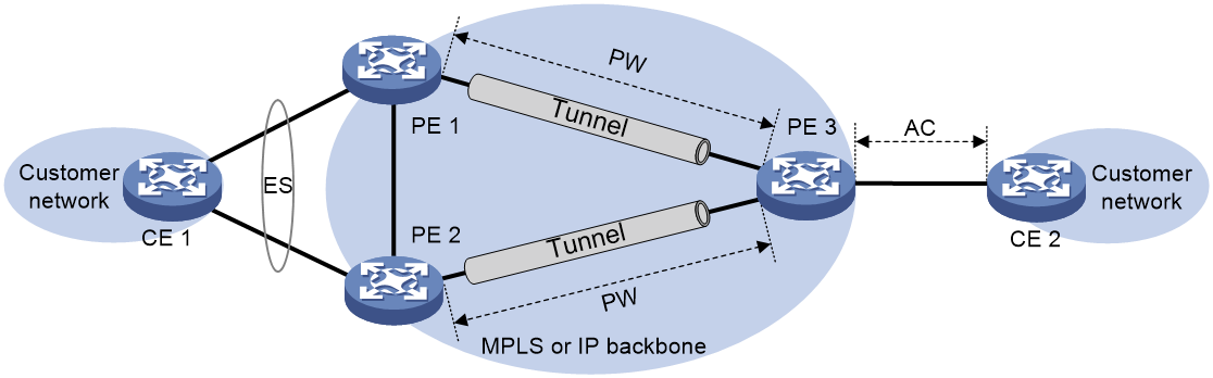
Operating mechanism
The device supports single-active redundancy mode and all-active redundancy mode of EVPN VPWS multihoming.
· Single-active mode—This mode allows one of the redundant PWs to forward traffic. When the main PW becomes unavailable because of device failure or link failure, traffic is switched to the backup PW for forwarding.
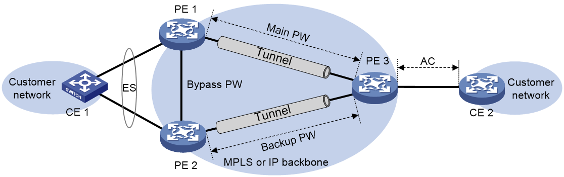
· All-active mode—This mode allows all redundant PWs to a multihomed site to load share traffic. When one PW fails, traffic is immediately switched to another PW.
When configuring single-active or all-active mode, configure a CLI-defined monitor policy that associates EAA with a track entry on the AC-side physical interface and the PW-side physical interface (used to establish an EVPN PW) of the PE device to make the two interfaces collaborate. In this way, when the underlay network on the PW side is disconnected, the AC-side interface will be placed in down state, which enables traffic from CE 1 to CE 2 to be forwarded through PE 2 and thus enhances network reliability.
Feature control commands
The following table shows the control commands for EVPN VPWS multihomed sites.
|
Task |
Command |
Remarks |
|
Set the redundancy mode. |
evpn redundancy-mode (interface view) |
To create a main/backup relationship between two EVPN PWs, use the single-active mode. To enable load balancing between EVPN PWs, use the all-active mode. |
Example: Configuring EVPN VPWS multihoming (single point failure scenario for multihoming PEs)
Network configuration
The customer network has two sites, CE 1 and CE 2. CE 1 is multi-homed to PE 1 and PE 2, while CE 2 is single-homed to PE 3. CE 1 and CE 2 aim to interconnect Site 1 with Site 2 by establishing an EVPN PW on the backbone network.
Multiple PEs connected to CE 1 form a redundancy group in all-active mode, which prevents network disruptions caused by single point failure on PEs and thus enhances network reliability.
Figure 24 Network diagram
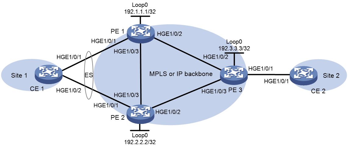
|
Device |
Interface |
IP address |
Device |
Interface |
IP address |
|
PE 1 |
Loop0 |
192.1.1.1/32 |
CE 1 |
HGE1/0/1 |
100.1.1.1/24 |
|
|
HGE1/0/1 |
- |
CE 2 |
HGE1/0/1 |
100.1.1.2/24 |
|
|
HGE1/0/2 |
10.1.1.1/24 |
PE 3 |
Loop0 |
192.3.3.3/32 |
|
|
HGE1/0/3 |
10.1.3.1/24 |
|
HGE1/0/1 |
- |
|
PE 2 |
Loop0 |
192.2.2.2/32 |
|
HGE1/0/2 |
10.1.1.2/24 |
|
|
HGE1/0/1 |
- |
|
HGE1/0/3 |
10.1.2.2/24 |
|
|
HGE1/0/2 |
10.1.2.1/24 |
|
|
|
|
|
HGE1/0/3 |
10.1.3.2/24 |
|
|
|
Procedures
1. Configure CE 1:
# Create Layer 3 aggregate interface 1, set the link aggregation mode to static, and then assign an IP address and subnet mask to the interface.
<CE1> system-view
[CE1] interface route-aggregation 1
[CE1-Route-Aggregation1] ip address 100.1.1.1 24
[CE1-Route-Aggregation1] quit
# Assign HundredGigE 1/0/1 and HundredGigE 1/0/2 to aggregation group 1.
[CE1] interface hundredgige 1/0/1
[CE1-HundredGigE1/0/1] port link-aggregation group 1
[CE1-HundredGigE1/0/1] quit
[CE1] interface hundredgige 1/0/2
[CE1-HundredGigE1/0/2] port link-aggregation group 1
[CE1-HundredGigE1/0/2] quit
2. Configure PE 1:
# Configure an LSR ID.
<PE1> system-view
[PE1] interface loopback 0
[PE1-LoopBack0] ip address 192.1.1.1 32
[PE1-LoopBack0] quit
[PE1] mpls lsr-id 192.1.1.1
# Enable L2VPN.
[PE1] l2vpn enable
# Enable LDP globally.
[PE1] mpls ldp
[PE1-ldp] quit
# Configure HundredGigE 1/0/2, which is connected to PE 3. Enable LDP on the interface.
[PE1] interface hundredgige 1/0/2
[PE1-HundredGigE1/0/2] ip address 10.1.1.1 24
[PE1-HundredGigE1/0/2] mpls enable
[PE1-HundredGigE1/0/2] mpls ldp enable
[PE1-HundredGigE1/0/2] quit
# Configure OSPF on PE 1 for establishing LSPs.
[PE1] ospf
[PE1-ospf-1] area 0
[PE1-ospf-1-area-0.0.0.0] network 10.1.1.0 0.0.0.255
[PE1-ospf-1-area-0.0.0.0] network 10.1.3.0 0.0.0.255
[PE1-ospf-1-area-0.0.0.0] network 192.1.1.1 0.0.0.0
[PE1-ospf-1-area-0.0.0.0] quit
[PE1-ospf-1] quit
# Establish IBGP connections among PE 1, PE 2, and PE 3, and configure BGP to advertise routes.
[PE1] bgp 100
[PE1-bgp-default] peer 192.2.2.2 as-number 100
[PE1-bgp-default] peer 192.2.2.2 connect-interface loopback 0
[PE1-bgp-default] peer 192.3.3.3 as-number 100
[PE1-bgp-default] peer 192.3.3.3 connect-interface loopback 0
[PE1-bgp-default] address-family l2vpn evpn
[PE1-bgp-default-evpn] peer 192.2.2.2 enable
[PE1-bgp-default-evpn] peer 192.3.3.3 enable
[PE1-bgp-default-evpn] peer 192.2.2.2 advertise encap-type mpls
[PE1-bgp-default-evpn] peer 192.3.3.3 advertise encap-type mpls
[PE1-bgp-default-evpn] quit
[PE1-bgp-default] quit
# On HundredGigE 1/ 0/1, which is connected to Site 1, configure an ESI and set the redundancy mode.
[PE1] interface hundredgige 1/0/1
[PE1-HundredGigE1/0/1] esi 1.1.1.1.1
[PE1-HundredGigE1/0/1] evpn redundancy-mode all-active
[PE1-HundredGigE1/0/1] quit
# Create cross-connect group vpna, create an EVPN instance for it, and enable MPLS encapsulation. Configure an RD and RTs for the EVPN instance.
[PE1] xconnect-group vpna
[PE1-xcg-vpna] evpn encapsulation mpls
[PE1-xcg-vpna-evpn-mpls] route-distinguisher 1:1
[PE1-xcg-vpna-evpn-mpls] vpn-target 1:1 export-extcommunity
[PE1-xcg-vpna-evpn-mpls] vpn-target 1:1 import-extcommunity
[PE1-xcg-vpna-evpn-mpls] quit
# Create cross-connect pw1, and map HundredGigE 1/0/1 to it. Create an EVPN PW on the cross-connect.
[PE1] xconnect-group vpna
[PE1-xcg-vpna] connection pw1
[PE1-xcg-vpna-pw1] ac interface hundredgige 1/0/1
[PE1-xcg-vpna-pw1-HundredGigE1/0/1] quit
[PE1-xcg-vpna-pw1] evpn local-service-id 1 remote-service-id 2
[PE1-xcg-vpna-pw1] quit
[PE1-xcg-vpna] quit
# Configure a track entry to monitor the state of HundredGigE 1/0/2.
[PE1] track 1 interface hundredgige 1/0/2
[PE1-track-1] quit
# Configure a TCL monitor policy for PE1 to automatically detect HundredGigE1/0/2 down events and shut down interface HundredGigE 1/0/1.
[PE1] rtm cli-policy policy1
[PE1-rtm-policy1] event track 1 state negative
[PE1-rtm-policy1] action 0 cli system-view
[PE1-rtm-policy1] action 1 cli interface HundredGigE1/0/1
[PE1-rtm-policy1] action 2 cli shutdown
[PE1-rtm-policy1] user-role network-admin
[PE1-rtm-policy1] commit
[PE1-rtm-policy1] quit
3. Configure PE 2:
# Configure an LSR ID.
<PE2> system-view
[PE2] interface loopback 0
[PE2-LoopBack0] ip address 192.2.2.2 32
[PE2-LoopBack0] quit
[PE2] mpls lsr-id 192.2.2.2
# Enable L2VPN.
[PE2] l2vpn enable
# Enable LDP globally.
[PE2] mpls ldp
[PE2-ldp] quit
# Configure HundredGigE 1/0/2, which is connected to PE 3. Enable LDP on the interface.
[PE2] interface hundredgige 1/0/2
[PE2-HundredGigE1/0/2] ip address 10.1.2.1 24
[PE2-HundredGigE1/0/2] mpls enable
[PE2-HundredGigE1/0/2] mpls ldp enable
[PE2-HundredGigE1/0/2] quit
# Configure OSPF on PE2 for establishing LSPs.
[PE2] ospf
[PE2-ospf-1] area 0
[PE2-ospf-1-area-0.0.0.0] network 10.1.2.0 0.0.0.255
[PE2-ospf-1-area-0.0.0.0] network 10.1.3.0 0.0.0.255
[PE2-ospf-1-area-0.0.0.0] network 192.2.2.2 0.0.0.0
[PE2-ospf-1-area-0.0.0.0] quit
[PE2-ospf-1] quit
# Establish IBGP connections among PE 1, PE 2, and PE 3, and configure BGP to advertise routes.
[PE2] bgp 100
[PE2-bgp-default] peer 192.1.1.1 as-number 100
[PE2-bgp-default] peer 192.1.1.1 connect-interface loopback 0
[PE2-bgp-default] peer 192.3.3.3 as-number 100
[PE2-bgp-default] peer 192.3.3.3 connect-interface loopback 0
[PE2-bgp-default] address-family l2vpn evpn
[PE2-bgp-default-evpn] peer 192.1.1.1 enable
[PE2-bgp-default-evpn] peer 192.3.3.3 enable
[PE2-bgp-default-evpn] peer 192.1.1.1 advertise encap-type mpls
[PE2-bgp-default-evpn] peer 192.3.3.3 advertise encap-type mpls
[PE2-bgp-default-evpn] quit
[PE2-bgp-default] quit
# On HundredGigE 1/0/1, which is connected to Site 1, configure an ESI and set the redundancy mode.
[PE2] interface hundredgige 1/0/1
[PE2-HundredGigE1/0/1] esi 1.1.1.1.1
[PE2-HundredGigE1/0/1] evpn redundancy-mode all-active
[PE2-HundredGigE1/0/1] quit
# Create cross-connect group vpna, create an EVPN instance for it, and enable MPLS encapsulation. Configure an RD and RTs for the EVPN instance.
[PE2] xconnect-group vpna
[PE2-xcg-vpna] evpn encapsulation mpls
[PE2-xcg-vpna-evpn-mpls] route-distinguisher 1:1
[PE2-xcg-vpna-evpn-mpls] vpn-target 1:1 export-extcommunity
[PE2-xcg-vpna-evpn-mpls] vpn-target 1:1 import-extcommunity
[PE2-xcg-vpna-evpn-mpls] quit
# Create cross-connect pw1, and map HundredGigE 1/0/1 to it. Create an EVPN PW on the cross-connect.
[PE2] xconnect-group vpna
[PE2-xcg-vpna] connection pw1
[PE2-xcg-vpna-pw1] ac interface hundredgige 1/0/1
[PE2-xcg-vpna-pw1-HundredGigE1/0/1] quit
[PE2-xcg-vpna-pw1] evpn local-service-id 1 remote-service-id 2
[PE2-xcg-vpna-pw1] quit
[PE2-xcg-vpna] quit
# Configure a track entry to monitor the state of HundredGigE 1/0/2.
[PE2] track 1 interface HundredGigE1/0/2
[PE2-track-1] quit
# Configure a TCL monitor policy for PE2 to automatically detect HundredGigE 1/0/2 down events and shut down interface HundredGigE 1/0/1.
[PE2] rtm cli-policy policy1
[PE2-rtm-policy1] event track 1 state negative
[PE2-rtm-policy1] action 0 cli system-view
[PE2-rtm-policy1] action 1 cli interface HundredGigE1/0/1
[PE2-rtm-policy1] action 2 cli shutdown
[PE2-rtm-policy1] user-role network-admin
[PE2-rtm-policy1] commit
[PE2-rtm-policy1] quit
4. Configure PE 3:
# Configure an LSR ID.
<PE3> system-view
[PE3] interface loopback 0
[PE3-LoopBack0] ip address 192.3.3.3 32
[PE3-LoopBack0] quit
[PE3] mpls lsr-id 192.3.3.3
# Enable L2VPN.
[PE3] l2vpn enable
# Enable LDP globally.
[PE3] mpls ldp
[PE3-ldp] quit
# Configure interfaces HundredGigE 1/0/2 and HundredGigE 1/0/3, which connect to PE1 and PE2, respectively. Enable LDP on the two interfaces.
[PE3] interface hundredgige 1/0/2
[PE3-HundredGigE1/0/2] ip address 10.1.1.2 24
[PE3-HundredGigE1/0/2] mpls enable
[PE3-HundredGigE1/0/2] mpls ldp enable
[PE3-HundredGigE1/0/2] quit
[PE3] interface hundredgige 1/0/3
[PE3-HundredGigE1/0/3] ip address 10.1.2.2 24
[PE3-HundredGigE1/0/3] mpls enable
[PE3-HundredGigE1/0/3] mpls ldp enable
[PE3-HundredGigE1/0/3] quit
# Configure OSPF on PE 3 for establishing LSPs.
[PE3] ospf
[PE3-ospf-1] area 0
[PE3-ospf-1-area-0.0.0.0] network 192.3.3.3 0.0.0.0
[PE3-ospf-1-area-0.0.0.0] network 10.1.1.0 0.0.0.255
[PE3-ospf-1-area-0.0.0.0] network 10.1.2.0 0.0.0.255
[PE3-ospf-1-area-0.0.0.0] quit
[PE3-ospf-1] quit
# Establish IBGP connections among PE 1, PE 2, and PE 3, and configure BGP to advertise routes.
[PE3] bgp 100
[PE3-bgp-default] peer 192.1.1.1 as-number 100
[PE3-bgp-default] peer 192.1.1.1 connect-interface loopback 0
[PE3-bgp-default] peer 192.2.2.2 as-number 100
[PE3-bgp-default] peer 192.2.2.2 connect-interface loopback 0
[PE3-bgp-default] address-family l2vpn evpn
[PE3-bgp-default-evpn] peer 192.1.1.1 enable
[PE3-bgp-default-evpn] peer 192.2.2.2 enable
[PE3-bgp-default-evpn] peer 192.1.1.1 advertise encap-type mpls
[PE3-bgp-default-evpn] peer 192.2.2.2 advertise encap-type mpls
[PE3-bgp-default-evpn] quit
[PE3-bgp-default] quit
# Create cross-connect group vpna, create an EVPN instance for it, and enable MPLS encapsulation. Configure an RD and RTs for the EVPN instance.
[PE3] xconnect-group vpna
[PE3-xcg-vpna] evpn encapsulation mpls
[PE3-xcg-vpna-evpn-mpls] route-distinguisher 1:1
[PE3-xcg-vpna-evpn-mpls] vpn-target 1:1 export-extcommunity
[PE3-xcg-vpna-evpn-mpls] vpn-target 1:1 import-extcommunity
[PE3-xcg-vpna-evpn-mpls] quit
# Create cross-connect pw1, and map HundredGigE 1/0/1 to it. Create an EVPN PW on the cross-connect.
[PE3] xconnect-group vpna
[PE3-xcg-vpna] connection pw1
[PE3-xcg-vpna-pw1] ac interface hundredgige 1/0/1
[PE3-xcg-vpna-pw1-HundredGigE1/0/1] quit
[PE3-xcg-vpna-pw1] evpn local-service-id 2 remote-service-id 1
[PE3-xcg-vpna-pw1] quit
[PE3-xcg-vpna] quit
5. Configure CE 2.
<CE2> system-view
[CE2] interface HundredGigE1/0/1
[CE2-HundredGigE1/0/1] ip address 100.1.1.2 24
[CE2-HundredGigE1/0/1] quit
Verifying the configuration
1. Display the configuration.
# Display PW information on PE1 to verify that an EVPN PW has been set up.
<PE1> display l2vpn pw
Flags: M - main, B - backup, E - ecmp, BY - bypass, H - hub link, S - spoke link
N - no split horizon, A - administration, ABY - ac-bypass
PBY - pw-bypass
Total number of PWs: 1
1 up, 0 blocked, 0 down, 0 defect, 0 idle, 0 duplicate
Xconnect-group Name: vpna
Peer PWID/RmtSite/SrvID In/Out Label Proto Flag Link ID State
192.3.3.3 2 710263/710265 EVPN M 0 Up
# Display the EVPN information of the cross-connect on PE 1.
<PE1> display evpn xconnect-group
Flags: P - Primary, B - Backup, C - Control word
Xconnect group name: vpna
Connection name: 1
ESI : 0001.0001.0001.0001.0001
Local service ID : 1
Remote service ID : 2
Control word : Disabled
In label : 710263
Local MTU : 1500
AC State : Up
PW type : VLAN
Nexthop ESI Out label Flags MTU state
192.3.3.3 0000.0000.0000.0000.0000 710265 P 1500 Up
192.2.2.2 0001.0001.0001.0001.0001 710124 P 1500 Up
# Display local ES information on PE 1.
<PE1> display evpn es local
Redundancy mode: A - All-active, S - Single-active
Xconnect-group name : vpna
ESI Tag ID DF address Mode State ESI label
0001.0001.0001.0001.0001 - 192.1.1.1 A Up -
# Display remote ES information on PE 1.
<PE1> display evpn es remote
Control Flags: P - Primary, B - Backup, C - Control word
Xconnect group name : vpna
ESI : 0001.0001.0001.0001.0001
Ethernet segment routes :
192.2.2.2
A-D per ES routes :
Peer IP Remote Redundancy mode
192.2.2.2 All-active
A-D per EVI routes :
Tag ID Peer IP Control Flags
1 192.2.2.2 P
# Verify that EVPN PW information can also be displayed on PE 2.
<PE2> display l2vpn pw
Flags: M - main, B - backup, E - ecmp, BY - bypass, H - hub link, S - spoke link
N - no split horizon, A - administration, ABY - ac-bypass
PBY - pw-bypass
Total number of PWs: 1
1 up, 0 blocked, 0 down, 0 defect, 0 idle, 0 duplicate
Xconnect-group Name: vpna
Peer PWID/RmtSite/SrvID In/Out Label Proto Flag Link ID State
192.3.3.3 2 710124/710265 EVPN M 1 Up
# Verify that EVPN PW information can also be displayed on PE 3.
<PE3> display l2vpn pw
Flags: M - main, B - backup, E - ecmp, BY - bypass, H - hub link, S - spoke link
N - no split horizon, A - administration, ABY - ac-bypass
PBY - pw-bypass
Total number of PWs: 2
2 up, 0 blocked, 0 down, 0 defect, 0 idle, 0 duplicate
Xconnect-group Name: vpna
Peer PWID/RmtSite/SrvID In/Out Label Proto Flag Link ID State
192.1.1.1 1 710265/710263 EVPN E 0 Up
192.2.2.2 1 710265/710124 EVPN E 0 Up
2. Perform traffic switchover.
# Verify that CE 1 and CE 2 can ping each other, the redundancy mode for the multihomed sites is all-active, and traffic is load-shared across the two PWs.
[CE1] display counters rate outbound interface
Usage: Bandwidth utilization in percentage
Interface Usage (%) Total (pps) Broadcast (pps) Multicast (pps)
HGE1/0/1 2 1206646 -- --
HGE1/0/2 2 1206978 -- --
Overflow: More than 14 digits.
--: Not supported.
# Verify that traffic switches over to another PW with zero packet loss when one PW fails.
[CE1] display counters rate outbound interface
Usage: Bandwidth utilization in percentage
Interface Usage (%) Total (pps) Broadcast (pps) Multicast (pps)
HGE1/0/1 0 0 -- --
HGE1/0/2 4 2413624 -- --
Overflow: More than 14 digits.
--: Not supported.
# After the PW fault is cleared, verify that traffic continues to be load-shared on both PWs with zero packet loss during recovery.
[CE1] display counters rate outbound interface
Usage: Bandwidth utilization in percentage
Interface Usage (%) Total (pps) Broadcast (pps) Multicast (pps)
HGE1/0/1 2 1206646 -- --
HGE1/0/2 2 1205964 -- --
Overflow: More than 14 digits.
--: Not supported.
FRR for EVPN VPWS
Feature overview
About this feature
FRR for EVPN VPWS minimizes the impact of AC or PW failure on the network and enhances network reliability and stability. FRR is applicable to both single-homing and multihoming EVPN VPWS networks.
FRR for EVPN VPWS provides bypass PWs (local FRR) and primary/backup PWs (remote FRR). In practical configuration, first set up a bypass PW, and then set up the primary/standby PWs. In the current software version, FRR for EVPN VPWS only supports setting up one primary PW and one backup PW.
Bypass PW implementation
In an EVPN VPWS multihomed site network, when an AC at a multihomed site fails, the PE connected to the AC advertises the local unreachable event to other PEs. Before receiving the local unreachable event, the remote PEs will still forward traffic to that PE, which will result in packet loss. You can establish a bypass PW between redundant PEs to temporarily forward traffic and avoid packet loss.
As shown in Figure 25, when the AC link fails on PE 2, PE 2 advertises the local unreachable event to PE 1 and PE 3 to prevent traffic from being forwarded through the PW between PE 1 and PE 2. During this time, data packets sent by PE 1 to PE 2 cannot be forwarded to CE 2 and are dropped. EVPN VPWS addresses this issue through the bypass PW feature, which establishes a bypass PW between redundant PEs. When an AC fails, PE 2 forwards traffic to PE 1 through the bypass PW. PE 3 then forwards traffic to CE 2 to reduce packet loss.
Figure 25 Schematic diagram of the bypass PW feature
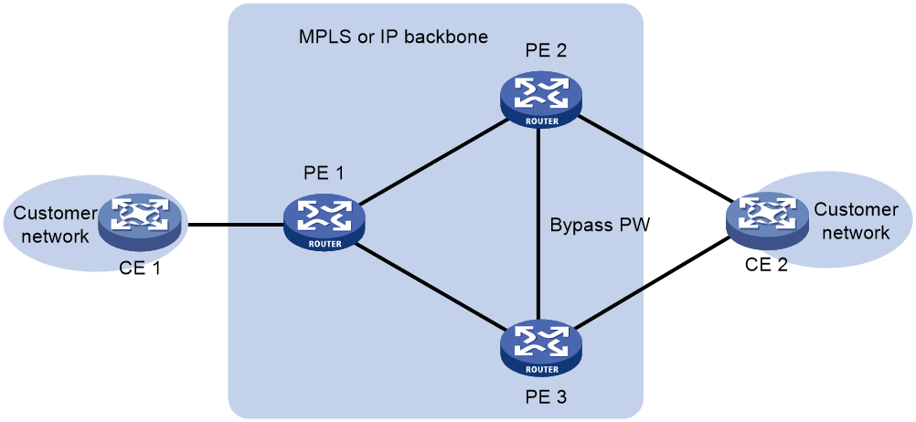
Primary/backup PW implementation
This feature establishes one primary PW and one backup PW between PEs. The primary PW forwards traffic, while the backup PW provides backup for the primary PW. When the primary PW fails, traffic switches to the backup PW to ensure uninterrupted traffic forwarding.
As shown in Figure 26, PE 1 and PE 2 are connected by RR 1 and RR 2. The RRs change the next hop attribute of routes and reassign MPLS labels to them based on routing policies when reflecting the routes. PE 1 and PE 2 select only RR 1 or RR 2 when establishing a PW. For high availability, you can enable the primary/backup PW feature on PE 1 for it to set up PWs to both RRs. PE 1 uses the primary PW to forward traffic as long as it is available. When the primary PW fails, PE 1 switches traffic to the backup PW. For more information about optimal route selection on PE 1, see BGP configuration in Layer 3—IP Routing Configuration Guide.
Figure 26 Schematic diagram of the primary/backup PW feature
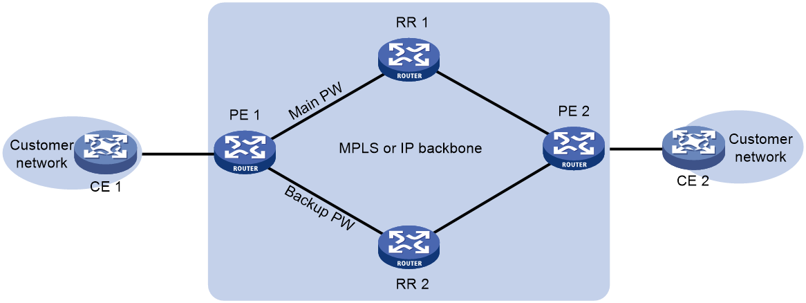
Feature control commands
The following table shows the control commands for EVPN VPWS FRR.
|
Task |
Command |
|
Enable local FRR globally for EVPN VPWS. |
evpn multihoming vpws-frr local (system view) |
|
Enable or disable local FRR on an EVPN instance. |
evpn frr local (cross-connect group EVPN instance view) |
|
Enable remote FRR globally. |
evpn vpws-frr remote (system view) |
|
Enable or disable remote FRR on an EVPN instance. |
evpn frr remote (cross-connect group EVPN instance view) |
Example: Configuring both local FRR and remote FRR for EVPN VPWS
Network configuration
As shown in Figure 27, establish the primary PW and backup PW between CE1 and PE1 and CE1 and PE2, respectively. The primary PW forwards traffic, while the backup PW provides backup for the primary PW. When the primary PW fails, traffic switches to the backup PW to ensure uninterrupted traffic forwarding.
PE 1, PE 2, and PE 3 are edge devices for the provider, and they all belong to AS 100. RR 1 and RR 2 reflect BGP routes between PEs. PE 1, PE 2, and PE 3 all run the EVPN VPWS feature, and PE 1 and PE 2 also run the bypass PW and primary/backup PW features to enhance network reliability. CE 1 and CE 2 achieve Layer 2 connectivity through the backbone network. The following information describes the deployment in detail:
· Establish a bypass PW between PE 1 and PE 2 and use LDP to create the public network tunnel that carries this PW.
· When reflecting routes to PE 1 and PE 2, RR 1 and RR 2 change the next hop attribute and reassign MPLS labels.
· Configure routing policies on RR 1 and RR 2 to change route attributes for optimal route selection.
· Each of PE 1 and PE 2 establishes two EVPN PWs to PE 3 through RR 1 and RR 2 separately, one primary PW and one backup PW.
· OSPF is used as the IGP in the AS.
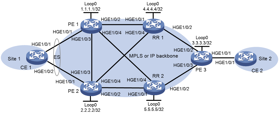
|
Device |
Interface |
IP address |
Device |
Interface |
IP address |
|
PE 1 |
Loop0 |
1.1.1.1/32 |
PE 3 |
Loop0 |
3.3.3.3/32 |
|
|
HGE1/0/1 |
- |
|
HGE1/0/1 |
- |
|
|
HGE1/0/2 |
10.1.1.1/24 |
|
HGE1/0/2 |
10.1.6.3/24 |
|
|
HGE1/0/3 |
10.1.2.1/24 |
|
HGE1/0/3 |
10.1.7.3/24 |
|
|
HGE1/0/4 |
10.1.3.1/24 |
RR 1 |
Loop0 |
4.4.4.4/32 |
|
PE 2 |
Loop0 |
2.2.2.2/32 |
|
HGE1/0/1 |
10.1.1.4/24 |
|
|
HGE1/0/1 |
- |
|
HGE1/0/2 |
10.1.6.4/24 |
|
|
HGE1/0/2 |
10.1.4.2/24 |
|
HGE1/0/4 |
10.1.5.4/24 |
|
|
HGE1/0/3 |
10.1.2.2/24 |
RR 2 |
Loop0 |
5.5.5.5/32 |
|
|
HGE1/0/4 |
10.1.5.2/24 |
|
HGE1/0/1 |
10.1.4.5/24 |
|
CE 1 |
RAGG1 |
100.1.1.1/24 |
|
HGE1/0/2 |
10.1.7.5/24 |
|
CE 2 |
HGE1/0/1 |
100.1.1.2/24 |
|
HGE1/0/4 |
10.1.3.5/24 |
Procedures
1. Configure CE 1:
# Create Layer 3 aggregate interface Route-Aggregation 1, set the link aggregation mode to static, and then assign an IP address and subnet mask to the interface.
<CE1> system-view
[CE1] interface route-aggregation 1
[CE1-Route-Aggregation1] ip address 100.1.1.1 24
[CE1-Route-Aggregation1] quit
# Assign HundredGigE 1/0/1 and HundredGigE 1/0/2 to aggregation group 1.
[CE1] interface hundredgige 1/0/1
[CE1-HundredGigE1/0/1] port link-aggregation group 1
[CE1-HundredGigE1/0/1] quit
[CE1] interface hundredgige 1/0/2
[CE1-HundredGigE1/0/2] port link-aggregation group 1
[CE1-HundredGigE1/0/2] quit
2. Configure PE 1:
# Configure an LSR ID.
<PE1> system-view
[PE1] interface loopback 0
[PE1-LoopBack0] ip address 1.1.1.1 32
[PE1-LoopBack0] quit
[PE1] mpls lsr-id 1.1.1.1
# Enable L2VPN.
[PE1] l2vpn enable
# Enable LDP globally.
[PE1] mpls ldp
[PE1-ldp] quit
# Enable the local FRR feature for EVPN VPWS globally.
[PE1] evpn multihoming vpws-frr local
# Configure HundredGigE 1/0/2, which is connected to RR 1. Enable LDP on the interface.
[PE1] interface hundredgige 1/0/2
[PE1-HundredGigE1/0/2] ip address 10.1.1.1 24
[PE1-HundredGigE1/0/2] mpls enable
[PE1-HundredGigE1/0/2] mpls ldp enable
[PE1-HundredGigE1/0/2] quit
# Configure HundredGigE 1/0/3, which is connected to PE 3. Enable LDP on the interface, which is used to create a bypass PW.
[PE1] interface hundredgige 1/0/3
[PE1-HundredGigE1/0/3] ip address 10.1.2.1 24
[PE1-HundredGigE1/0/3] mpls enable
[PE1-HundredGigE1/0/3] mpls ldp enable
[PE1-HundredGigE1/0/3] quit
# Configure HundredGigE 1/0/4, which is connected to RR 2. Enable LDP on the interface.
[PE1] interface hundredgige 1/0/4
[PE1-HundredGigE1/0/4] ip address 10.1.3.1 24
[PE1-HundredGigE1/0/4] mpls enable
[PE1-HundredGigE1/0/4] mpls ldp enable
[PE1-HundredGigE1/0/4] quit
# Run OSPF on PE 1 to ensure that devices can reach each other at Layer 3.
[PE1] ospf
[PE1-ospf-1] area 0
[PE1-ospf-1-area-0.0.0.0] network 10.1.1.0 0.0.0.255
[PE1-ospf-1-area-0.0.0.0] network 10.1.2.0 0.0.0.255
[PE1-ospf-1-area-0.0.0.0] network 10.1.3.0 0.0.0.255
[PE1-ospf-1-area-0.0.0.0] network 1.1.1.1 0.0.0.0
[PE1-ospf-1-area-0.0.0.0] quit
[PE1-ospf-1] quit
# Configure PE 1 to establish IBGP connections to RR 1 and RR 2, and configure BGP to advertise EVPN routing information.
[PE1] bgp 100
[PE1-bgp-default] peer 4.4.4.4 as-number 100
[PE1-bgp-default] peer 4.4.4.4 connect-interface loopback 0
[PE1-bgp-default] peer 5.5.5.5 as-number 100
[PE1-bgp-default] peer 5.5.5.5 connect-interface loopback 0
[PE1-bgp-default] address-family l2vpn evpn
[PE1-bgp-default-evpn] peer 4.4.4.4 enable
[PE1-bgp-default-evpn] peer 5.5.5.5 enable
[PE1-bgp-default-evpn] peer 4.4.4.4 advertise encap-type mpls
[PE1-bgp-default-evpn] peer 5.5.5.5 advertise encap-type mpls
[PE1-bgp-default-evpn] quit
[PE1-bgp-default] quit
# On HundredGigE 1/ 0/1, which is connected to Site 1, configure an ESI and set the redundancy mode.
[PE1] interface hundredgige 1/0/1
[PE1-HundredGigE1/0/1] esi 1.1.1.1.1
[PE1-HundredGigE1/0/1] evpn redundancy-mode all-active
[PE1-HundredGigE1/0/1] quit
# Create cross-connect group vpna, create an EVPN instance for it, and enable MPLS encapsulation. Configure an RD and RTs for the EVPN instance.
[PE1] xconnect-group vpna
[PE1-xcg-vpna] evpn encapsulation mpls
[PE1-xcg-vpna-evpn-mpls] route-distinguisher 1:1
[PE1-xcg-vpna-evpn-mpls] vpn-target 1:1 export-extcommunity
[PE1-xcg-vpna-evpn-mpls] vpn-target 1:1 import-extcommunity
[PE1-xcg-vpna-evpn-mpls] quit
# Create cross-connect pw1, and map HundredGigE 1/0/1 to it. Create an EVPN PW on the cross-connect.
[PE1] xconnect-group vpna
[PE1-xcg-vpna] connection pw1
[PE1-xcg-vpna-pw1] ac interface hundredgige 1/0/1
[PE1-xcg-vpna-pw1-HundredGigE1/0/1] quit
[PE1-xcg-vpna-pw1] evpn local-service-id 1 remote-service-id 2
[PE1-xcg-vpna-pw1] quit
[PE1-xcg-vpna] quit
# Enable the remote FRR feature globally for EVPN VPWS to establish one primary PW and one backup PW between PE 1 and PE 3.
[PE1] evpn vpws-frr remote
3. Configure PE 2:
# Configure an LSR ID.
<PE2> system-view
[PE2] interface loopback 0
[PE2-LoopBack0] ip address 2.2.2.2 32
[PE2-LoopBack0] quit
[PE2] mpls lsr-id 2.2.2.2
# Enable L2VPN.
[PE2] l2vpn enable
# Enable LDP globally.
[PE2] mpls ldp
[PE2-ldp] quit
# Enable the local FRR feature for EVPN VPWS globally.
[PE2] evpn multihoming vpws-frr local
# Configure HundredGigE 1/0/2, which is connected to RR 2. Enable LDP on the interface.
[PE2] interface hundredgige 1/0/2
[PE2-HundredGigE1/0/2] ip address 10.1.4.2 24
[PE2-HundredGigE1/0/2] mpls enable
[PE2-HundredGigE1/0/2] mpls ldp enable
[PE2-HundredGigE1/0/2] quit
# Configure HundredGigE 1/0/3, which is connected to PE 1. Enable LDP on the interface, which is used to create a bypass PW.
[PE2] interface hundredgige 1/0/3
[PE2-HundredGigE1/0/3] ip address 10.1.2.2 24
[PE2-HundredGigE1/0/3] mpls enable
[PE2-HundredGigE1/0/3] mpls ldp enable
[PE2-HundredGigE1/0/3] quit
# Configure HundredGigE 1/0/4, which is connected to RR 1. Enable LDP on the interface.
[PE2] interface hundredgige 1/0/4
[PE2-HundredGigE1/0/4] ip address 10.1.5.2 24
[PE2-HundredGigE1/0/4] mpls enable
[PE2-HundredGigE1/0/4] mpls ldp enable
[PE2-HundredGigE1/0/4] quit
# Run OSPF on PE 2 to ensure that devices can reach each other at Layer 3.
[PE2] ospf
[PE2-ospf-1] area 0
[PE2-ospf-1-area-0.0.0.0] network 10.1.2.0 0.0.0.255
[PE2-ospf-1-area-0.0.0.0] network 10.1.4.0 0.0.0.255
[PE2-ospf-1-area-0.0.0.0] network 10.1.5.0 0.0.0.255
[PE2-ospf-1-area-0.0.0.0] network 2.2.2.2 0.0.0.0
[PE2-ospf-1-area-0.0.0.0] quit
[PE2-ospf-1] quit
# Configure PE 2 to establish IBGP connections to RR 1 and RR 2, and configure BGP to advertise EVPN routing information.
[PE2] bgp 100
[PE2-bgp-default] peer 4.4.4.4 as-number 100
[PE2-bgp-default] peer 4.4.4.4 connect-interface loopback 0
[PE2-bgp-default] peer 5.5.5.5 as-number 100
[PE2-bgp-default] peer 5.5.5.5 connect-interface loopback 0
[PE2-bgp-default] address-family l2vpn evpn
[PE2-bgp-default-evpn] peer 4.4.4.4 enable
[PE2-bgp-default-evpn] peer 5.5.5.5 enable
[PE2-bgp-default-evpn] peer 4.4.4.4 advertise encap-type mpls
[PE2-bgp-default-evpn] peer 5.5.5.5 advertise encap-type mpls
[PE2-bgp-default-evpn] quit
[PE2-bgp-default] quit
# On HundredGigE 1/ 0/1, which is connected to Site 1, configure an ESI and set the redundancy mode.
[PE2] interface hundredgige 1/0/1
[PE2-HundredGigE1/0/1] esi 1.1.1.1.1
[PE2-HundredGigE1/0/1] evpn redundancy-mode all-active
[PE2-HundredGigE1/0/1] quit
# Create cross-connect group vpna, create an EVPN instance for it, and enable MPLS encapsulation. Configure an RD and RTs for the EVPN instance.
[PE2] xconnect-group vpna
[PE2-xcg-vpna] evpn encapsulation mpls
[PE2-xcg-vpna-evpn-mpls] route-distinguisher 1:1
[PE2-xcg-vpna-evpn-mpls] vpn-target 1:1 export-extcommunity
[PE2-xcg-vpna-evpn-mpls] vpn-target 1:1 import-extcommunity
[PE2-xcg-vpna-evpn-mpls] quit
# Create cross-connect pw1, and map HundredGigE 1/0/1 to it. Create an EVPN PW on the cross-connect.
[PE2] xconnect-group vpna
[PE2-xcg-vpna] connection pw1
[PE2-xcg-vpna-pw1] ac interface hundredgige 1/0/1
[PE2-xcg-vpna-pw1-HundredGigE1/0/1] quit
[PE2-xcg-vpna-pw1] evpn local-service-id 1 remote-service-id 2
[PE2-xcg-vpna-pw1] quit
[PE2-xcg-vpna] quit
# Enable the remote FRR feature globally for EVPN VPWS to establish one primary PW and one backup PW between PE 2 and PE 3.
[PE2] evpn vpws-frr remote
4. Configure PE 1:
# Configure an LSR ID.
<RR1> system-view
[RR1] interface loopback 0
[RR1-LoopBack0] ip address 4.4.4.4 32
[RR1-LoopBack0] quit
[RR1] mpls lsr-id 4.4.4.4
# Enable L2VPN.
[RR1] l2vpn enable
# Enable LDP globally.
[RR1] mpls ldp
[RR1-ldp] quit
# Configure HundredGigE 1/0/1, which is connected to PE 1. Enable LDP on the interface.
[RR1] interface hundredgige 1/0/1
[RR1-HundredGigE1/0/1] ip address 10.1.1.4 24
[RR1-HundredGigE1/0/1] mpls enable
[RR1-HundredGigE1/0/1] mpls ldp enable
[RR1-HundredGigE1/0/1] quit
# Configure HundredGigE 1/0/4, which is connected to PE 2. Enable LDP on the interface.
[RR1] interface hundredgige 1/0/4
[RR1-HundredGigE1/0/4] ip address 10.1.5.4 24
[RR1-HundredGigE1/0/4] mpls enable
[RR1-HundredGigE1/0/4] mpls ldp enable
[RR1-HundredGigE1/0/4] quit
# Configure HundredGigE 1/0/2, which is connected to PE 3. Enable LDP on the interface.
[RR1] interface hundredgige 1/0/2
[RR1-HundredGigE1/0/2] ip address 10.1.6.4 24
[RR1-HundredGigE1/0/2] mpls enable
[RR1-HundredGigE1/0/2] mpls ldp enable
[RR1-HundredGigE1/0/2] quit
# Run OSPF on RR 1 to ensure that devices can reach each other at Layer 3.
[RR1] ospf
[RR1-ospf-1] area 0
[RR1-ospf-1-area-0.0.0.0] network 10.1.1.0 0.0.0.255
[RR1-ospf-1-area-0.0.0.0] network 10.1.5.0 0.0.0.255
[RR1-ospf-1-area-0.0.0.0] network 10.1.6.0 0.0.0.255
[RR1-ospf-1-area-0.0.0.0] network 4.4.4.4 0.0.0.0
[RR1-ospf-1-area-0.0.0.0] quit
[RR1-ospf-1] quit
# Configure routing policies used for modifying the costs of routes.
[RR1] route-policy policy1 permit node 10
[RR1-route-policy-policy1-10] if-match route-type bgp-evpn-ad
[RR1-route-policy-policy1-10] apply cost 200
[RR1-route-policy-policy1-10] quit
[RR1] route-policy policy2 permit node 20
[RR1-route-policy-policy2-10] if-match route-type bgp-evpn-ad
[RR1-route-policy-policy2-10] apply cost 500
[RR1-route-policy-policy2-10] quit
# Configure RR 1 to establish IBGP connections to PE 1, PE 2, and PE 3.
[RR1] bgp 100
[RR1-bgp-default] peer 1.1.1.1 as-number 100
[RR1-bgp-default] peer 2.2.2.2 as-number 100
[RR1-bgp-default] peer 3.3.3.3 as-number 100
[RR1-bgp-default] peer 1.1.1.1 connect-interface loopback 0
[RR1-bgp-default] peer 2.2.2.2 connect-interface loopback 0
[RR1-bgp-default] peer 3.3.3.3 connect-interface loopback 0
# Configure BGP to advertise BGP EVPN routes and disable route target filtering for BGP EVPN routes.
[RR1-bgp-default] address-family l2vpn evpn
[RR1-bgp-default-evpn] peer 1.1.1.1 enable
[RR1-bgp-default-evpn] peer 2.2.2.2 enable
[RR1-bgp-default-evpn] peer 3.3.3.3 enable
[RR1-bgp-default-evpn] peer 1.1.1.1 advertise encap-type mpls
[RR1-bgp-default-evpn] peer 2.2.2.2 advertise encap-type mpls
[RR1-bgp-default-evpn] peer 3.3.3.3 advertise encap-type mpls
[RR1-bgp-default-evpn] undo policy vpn-target
# Configure RR 1 as a route reflector (RR).
[RR1-bgp-default-evpn] peer 1.1.1.1 reflect-client
[RR1-bgp-default-evpn] peer 2.2.2.2 reflect-client
[RR1-bgp-default-evpn] peer 3.3.3.3 reflect-client
# Enable RR 1 to change the attributes of routes to be reflected.
[RR1-bgp-default-evpn] reflect change-path-attribute
# Configure RR 1 to change the next hop attributes when reflecting routes to PE 1 and PE 2.
[RR1-bgp-default-evpn] peer 1.1.1.1 next-hop-local
[RR1-bgp-default-evpn] peer 2.2.2.2 next-hop-local
# Add PE 1 and PE 2 to the nearby cluster, so that RR 1 reflects routes between PE 1 and PE 2 without changing the next hop attribute.
[RR1-bgp-default-evpn] peer 1.1.1.1 reflect-nearby-group
[RR1-bgp-default-evpn] peer 2.2.2.2 reflect-nearby-group
# Apply routing policy policy1 to the routes advertised to IBGP peer 1.1.1.1.
[RR1-bgp-default-evpn] peer 1.1.1.1 route-policy policy1 export
# Apply routing policy policy2 to the routes advertised to IBGP peer 2.2.2.2.
[RR1-bgp-default-evpn] peer 2.2.2.2 route-policy policy2 export
[RR1-bgp-default-evpn] quit
[RR1-bgp-default] quit
5. Configure RR 2:
# Configure an LSR ID.
<RR2> system-view
[RR2] interface loopback 0
[RR2-LoopBack0] ip address 5.5.5.5 32
[RR2-LoopBack0] quit
[RR2] mpls lsr-id 5.5.5.5
# Enable L2VPN.
[RR2] l2vpn enable
# Enable LDP globally.
[RR2] mpls ldp
[RR2-ldp] quit
# Configure HundredGigE 1/0/4, which is connected to PE 1. Enable LDP on the interface.
[RR2] interface hundredgige 1/0/4
[RR2-HundredGigE1/0/4] ip address 10.1.3.5 24
[RR2-HundredGigE1/0/4] mpls enable
[RR2-HundredGigE1/0/4] mpls ldp enable
[RR2-HundredGigE1/0/4] quit
# Configure HundredGigE 1/0/1, which is connected to PE 2. Enable LDP on the interface.
[RR2] interface hundredgige 1/0/1
[RR2-HundredGigE1/0/1] ip address 10.1.4.5 24
[RR2-HundredGigE1/0/1] mpls enable
[RR2-HundredGigE1/0/1] mpls ldp enable
[RR2-HundredGigE1/0/1] quit
# Configure HundredGigE 1/0/2, which is connected to PE 3. Enable LDP on the interface.
[RR2] interface hundredgige 1/0/2
[RR2-HundredGigE1/0/2] ip address 10.1.7.5 24
[RR2-HundredGigE1/0/2] mpls enable
[RR2-HundredGigE1/0/2] mpls ldp enable
[RR2-HundredGigE1/0/2] quit
# Run OSPF on RR 2 to ensure that devices can reach each other at Layer 3.
[RR2] ospf
[RR2-ospf-1] area 0
[RR2-ospf-1-area-0.0.0.0] network 10.1.3.0 0.0.0.255
[RR2-ospf-1-area-0.0.0.0] network 10.1.4.0 0.0.0.255
[RR2-ospf-1-area-0.0.0.0] network 10.1.7.0 0.0.0.255
[RR2-ospf-1-area-0.0.0.0] network 5.5.5.5 0.0.0.0
[RR2-ospf-1-area-0.0.0.0] quit
[RR2-ospf-1] quit
# Configure routing policies used for modifying the costs of routes.
[RR2] route-policy policy1 permit node 10
[RR2-route-policy-policy1-10] if-match route-type bgp-evpn-ad
[RR2-route-policy-policy1-10] apply cost 200
[RR2-route-policy-policy1-10] quit
[RR2] route-policy policy2 permit node 20
[RR2-route-policy-policy2-10] if-match route-type bgp-evpn-ad
[RR2-route-policy-policy2-10] apply cost 500
[RR2-route-policy-policy2-10] quit
# Configure RR 2 to establish IBGP connections to PE 1, PE 2, and PE 3.
[RR2] bgp 100
[RR2-bgp-default] peer 1.1.1.1 as-number 100
[RR2-bgp-default] peer 2.2.2.2 as-number 100
[RR2-bgp-default] peer 3.3.3.3 as-number 100
[RR2-bgp-default] peer 1.1.1.1 connect-interface loopback 0
[RR2-bgp-default] peer 2.2.2.2 connect-interface loopback 0
[RR2-bgp-default] peer 3.3.3.3 connect-interface loopback 0
# Configure BGP to advertise BGP EVPN routes and disable route target filtering for BGP EVPN routes.
[RR2-bgp-default] address-family l2vpn evpn
[RR2-bgp-default-evpn] peer 1.1.1.1 enable
[RR2-bgp-default-evpn] peer 2.2.2.2 enable
[RR2-bgp-default-evpn] peer 3.3.3.3 enable
[RR2-bgp-default-evpn] peer 1.1.1.1 advertise encap-type mpls
[RR2-bgp-default-evpn] peer 2.2.2.2 advertise encap-type mpls
[RR2-bgp-default-evpn] peer 3.3.3.3 advertise encap-type mpls
[RR2-bgp-default-evpn] undo policy vpn-target
# Configure RR 2 as a route reflector (RR).
[RR2-bgp-default-evpn] peer 1.1.1.1 reflect-client
[RR2-bgp-default-evpn] peer 2.2.2.2 reflect-client
[RR2-bgp-default-evpn] peer 3.3.3.3 reflect-client
# Enable RR 2 to change the attributes of routes to be reflected.
[RR2-bgp-default-evpn] reflect change-path-attribute
# Configure RR 2 to change the next hop attributes when reflecting routes to PE 1 and PE 2.
[RR2-bgp-default-evpn] peer 1.1.1.1 next-hop-local
[RR2-bgp-default-evpn] peer 2.2.2.2 next-hop-local
# Add PE 1 and PE 2 to the nearby cluster, so that RR 2 reflects routes between PE 1 and PE 2 without changing the next hop attribute.
[RR2-bgp-default-evpn] peer 1.1.1.1 reflect-nearby-group
[RR2-bgp-default-evpn] peer 2.2.2.2 reflect-nearby-group
# Apply routing policy policy1 to the routes advertised to IBGP peer 1.1.1.1.
[RR2-bgp-default-evpn] peer 1.1.1.1 route-policy policy1 export
# Apply routing policy policy2 to the routes advertised to IBGP peer 2.2.2.2.
[RR2-bgp-default-evpn] peer 2.2.2.2 route-policy policy2 export
[RR2-bgp-default-evpn] quit
[RR2-bgp-default] quit
6. Configure PE 3:
# Configure an LSR ID.
<PE3> system-view
[PE3] interface loopback 0
[PE3-LoopBack0] ip address 3.3.3.3 32
[PE3-LoopBack0] quit
[PE3] mpls lsr-id 3.3.3.3
# Enable L2VPN.
[PE3] l2vpn enable
# Enable LDP globally.
[PE3] mpls ldp
[PE3-ldp] quit
# Enable the local FRR feature for EVPN VPWS globally.
[PE3] evpn multihoming vpws-frr local
# Configure HundredGigE 1/0/2, which is connected to RR 1. Enable LDP on the interface.
[PE3] interface hundredgige 1/0/2
[PE3-HundredGigE1/0/2] ip address 10.1.6.3 24
[PE3-HundredGigE1/0/2] mpls enable
[PE3-HundredGigE1/0/2] mpls ldp enable
[PE3-HundredGigE1/0/2] quit
# Configure HundredGigE 1/0/3, which is connected to RR 2. Enable LDP on the interface.
[PE3] interface hundredgige 1/0/3
[PE3-HundredGigE1/0/3] ip address 10.1.7.3 24
[PE3-HundredGigE1/0/3] mpls enable
[PE3-HundredGigE1/0/3] mpls ldp enable
[PE3-HundredGigE1/0/3] quit
# Configure OSPF on PE 1 for establishing LSPs and neighbors.
[PE3] ospf
[PE3-ospf-1] area 0
[PE3-ospf-1-area-0.0.0.0] network 10.1.6.0 0.0.0.255
[PE3-ospf-1-area-0.0.0.0] network 10.1.7.0 0.0.0.255
[PE3-ospf-1-area-0.0.0.0] network 3.3.3.3 0.0.0.0
[PE3-ospf-1-area-0.0.0.0] quit
[PE3-ospf-1] quit
# Configure PE 3 to establish IBGP connections to RR 1 and RR 2, and configure BGP to advertise EVPN routing information.
[PE3] bgp 100
[PE3-bgp-default] peer 4.4.4.4 as-number 100
[PE3-bgp-default] peer 4.4.4.4 connect-interface loopback 0
[PE3-bgp-default] peer 5.5.5.5 as-number 100
[PE3-bgp-default] peer 5.5.5.5 connect-interface loopback 0
[PE3-bgp-default] address-family l2vpn evpn
[PE3-bgp-default-evpn] peer 4.4.4.4 enable
[PE3-bgp-default-evpn] peer 5.5.5.5 enable
[PE3-bgp-default-evpn] peer 4.4.4.4 advertise encap-type mpls
[PE3-bgp-default-evpn] peer 5.5.5.5 advertise encap-type mpls
[PE3-bgp-default-evpn] quit
[PE3-bgp-default] quit
# Create cross-connect group vpna, create an EVPN instance for it, and enable MPLS encapsulation. Configure an RD and RTs for the EVPN instance.
[PE3] xconnect-group vpna
[PE3-xcg-vpna] evpn encapsulation mpls
[PE3-xcg-vpna-evpn-mpls] route-distinguisher 1:1
[PE3-xcg-vpna-evpn-mpls] vpn-target 1:1 export-extcommunity
[PE3-xcg-vpna-evpn-mpls] vpn-target 1:1 import-extcommunity
[PE3-xcg-vpna-evpn-mpls] quit
# Create cross-connect pw1, and map HundredGigE 1/0/1 to it. Create an EVPN PW on the cross-connect.
[PE3] xconnect-group vpna
[PE3-xcg-vpna] connection pw1
[PE3-xcg-vpna-pw1] ac interface gigabitethernet1/0/1
[PE3-xcg-vpna-pw1-HundredGigE1/0/1] quit
[PE3-xcg-vpna-pw1] evpn local-service-id 2 remote-service-id 1
[PE3-xcg-vpna-pw1] quit
[PE3-xcg-vpna] quit
7. Configure CE 2.
<CE2> system-view
[CE2] interface hundredgige 1/0/1
[CE2-HundredGigE1/0/1] ip address 100.1.1.2 24
[CE2-HundredGigE1/0/1] quit
Verifying the configuration
1. Display PW information.
# Display the PW information on PE 1. Verify that PE 1 has established two PWs (one primary and one backup) to PE 3 and a bypass PW to PE 2.
<PE1> display l2vpn pw
Flags: M - main, B - backup, E - ecmp, BY - bypass, H - hub link, S - spoke link
N - no split horizon, A - administration, ABY - ac-bypass
PBY - pw-bypass
Total number of PWs: 3
1 up, 2 blocked, 0 down, 0 defect, 0 idle, 0 duplicate
Xconnect-group Name: vpna
Peer PWID/RmtSite/SrvID In/Out Label Proto Flag Link ID State
4.4.4.4 2 1151/1403 EVPN M 0 Up
5.5.5.5 2 1151/1275 EVPN B 0 Blocked
2.2.2.2 1 1151/1151 EVPN ABY 1 Blocked
# Display the PW information on PE 2. Verify that PE 2 has established two PWs (one primary and one backup) to PE 3 and a bypass PW to PE 1.
<PE2> display l2vpn pw
Flags: M - main, B - backup, E - ecmp, BY - bypass, H - hub link, S - spoke link
N - no split horizon, A - administration, ABY - ac-bypass
PBY - pw-bypass
Total number of PWs: 3
1 up, 2 blocked, 0 down, 0 defect, 0 idle, 0 duplicate
Xconnect-group Name: vpna
Peer PWID/RmtSite/SrvID In/Out Label Proto Flag Link ID State
5.5.5.5 2 1152/1404 EVPN M 0 Up
4.4.4.4 2 1152/1276 EVPN B 0 Blocked
1.1.1.1 1 1152/1152 EVPN ABY 1 Blocked
2. Verify inter-site connectivity.
# Verify that CE 1 and CE 2 can ping each other.
3. Perform traffic switchover.
# When the primary PW is operating correctly, verify that traffic from CE1 to CE2 is sent through the outgoing interface HGE1/0/1 connected to PW1.
[CE1] display counters rate outbound interface
Usage: Bandwidth utilization in percentage
Interface Usage (%) Total (pps) Broadcast (pps) Multicast (pps)
HGE1/0/1 4 2413624 -- --
HGE1/0/2 0 -- --
Overflow: More than 14 digits.
--: Not supported.
# Verify that traffic switches over to another PW with zero packet loss when one PW fails.
[CE1] display counters rate outbound interface
Usage: Bandwidth utilization in percentage
Interface Usage (%) Total (pps) Broadcast (pps) Multicast (pps)
HGE1/0/1 0 0 -- --
HGE1/0/2 4 2413624 -- --
Overflow: More than 14 digits.
--: Not supported.
Zero packet loss technology in an SR-MPLS network
SR-MPLS TE policy hot standby
Feature overview
About this feature
If an SR-MPLS TE policy has multiple valid candidate paths, the device selects the candidate path with the highest preference. If the selected path fails, the SR-MPLS TE policy must select another candidate path. Because selecting a new valid candidate path takes some time, packet loss might occur during the forwarding path switching process, affecting service traffic forwarding.
The SR-MPLS TE policy hot standby feature can solve this issue. This feature allows using the path with the highest precedence as the primary path and the path with the second-highest precedence as the standby backup path when multiple valid candidate paths are available. When the primary path fails, traffic immediately switches to the backup path for forwarding, achieving zero packet loss.
Operating mechanism
Hot standby for SR-MPLS TE policy involves protecting the primary candidate path using the backup candidate path. If multiple candidate paths exist in an SR-MPLS TE policy, the policy uses the candidate path with the highest precedence as the primary path and the one with the second-highest precedence as the standby backup path. As shown in Figure 28, if all the SID lists for the primary path are faulty, the backup candidate path immediately takes over to minimize service interruption.
Figure 28 SR-MPLS TE policy hot standby backup diagram
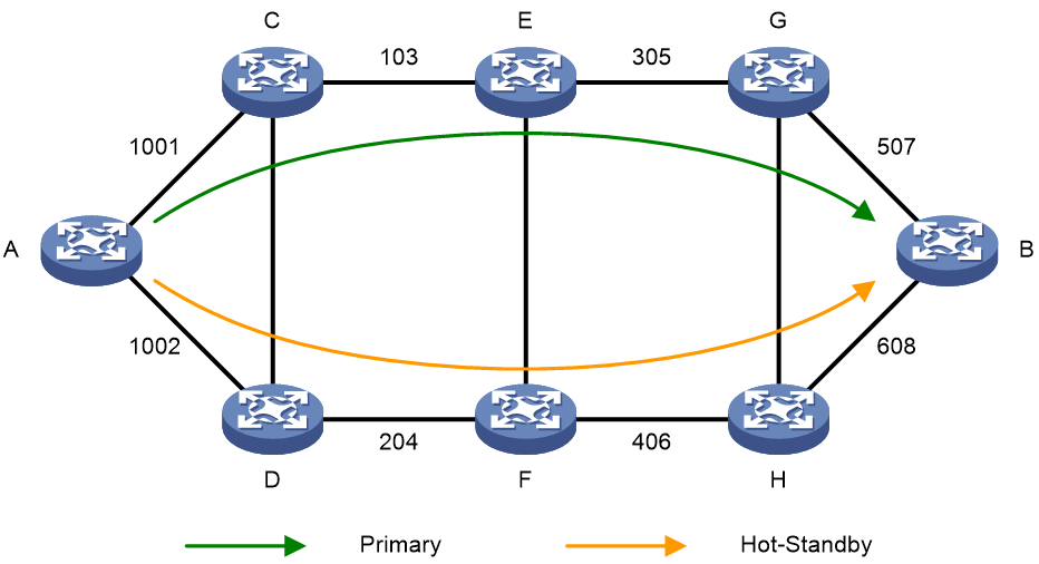
In conjunction with SR-MPLS TE policy hot standby, SBFD detects connectivity for the SID lists associated with the candidate paths with the highest two preference values in an SR-MPLS TE policy. If all forwarding paths corresponding to the SID lists in the highest-precedence candidate path fail, the policy switches the traffic to the backup path. When traffic is switched to the backup path, the primary and backup paths are recalculated. The original backup path will act as the primary path, and a new valid candidate path will be selected as the new backup path. When both the primary and backup paths fail, the SR-MPLS TE policy will recalculate the primary and backup paths.
Feature control commands
The following table shows the control commands for SR-MPLS TE policy hot standby.
The configuration in SR TE view applies to all SR-MPLS TE policies globally, while the configuration in SR-MPLS TE policy view only applies to the current SR-MPLS TE policy. The policy-specific configuration takes precedence over the global configuration.
The following table shows the control commands for SR-MPLS TE policy hot standby:
|
Task |
Command |
|
Enable hot standby backup for all SR-MPLS TE policies. |
sr-policy backup hot-standby enable (SR TE view) |
|
Enable hot standby backup for an SR-MPLS TE policy. |
backup hot-standby (SR-MPLS TE policy view) |
Example: Configuring SR-MPLS TE policy hot standby for zero packet loss
Network configuration
As shown in Figure 29, deploy an SR-MPLS TE policy in the IGP network. Path Device A-Device D is the primary path with the highest precedence, and path Device A-Device B-Device C-Device D is the backup path. Configure hot standby backup for the SR-MPLS TE policy to quickly switchover traffic to the backup path in case of primary path failure, achieving zero packet loss for the primary path traffic.
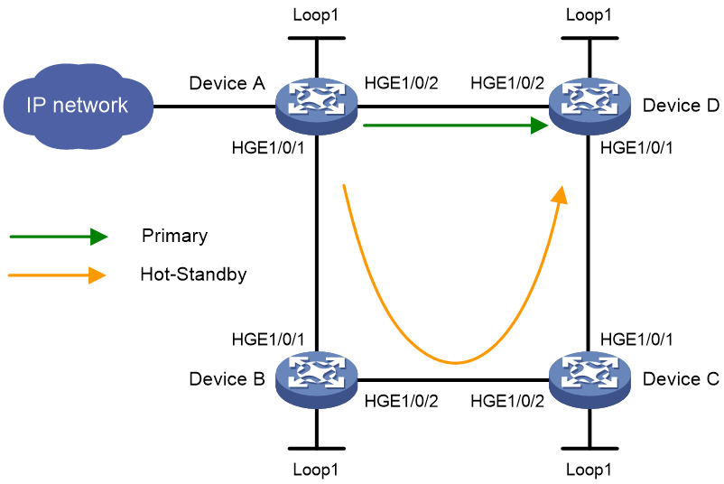
|
Device |
Interface |
IP address |
Device |
Interface |
IP address |
|
Device A |
Loop1 |
1.1.1.1/32 |
Device B |
Loop1 |
2.2.2.2/32 |
|
|
HGE1/0/1 |
12.0.0.1/24 |
|
HGE1/0/1 |
12.0.0.2/24 |
|
|
HGE1/0/2 |
14.0.0.1/24 |
|
HGE1/0/2 |
23.0.0.2/24 |
|
Device C |
Loop1 |
3.3.3.3/32 |
Device D |
Loop1 |
4.4.4.4/32 |
|
|
HGE1/0/1 |
34.0.0.3/24 |
|
HGE1/0/1 |
34.0.0.4/24 |
|
|
HGE1/0/2 |
23.0.0.3/24 |
|
HGE1/0/2 |
14.0.0.4/24 |
Major configuration steps
1. Assign an IP address to each interface. (Details not shown.)
2. Configure Device A:
# Configure IS-IS to implement Layer 3 connectivity, and set the IS-IS cost style to wide.
<DeviceA> system-view
[DeviceA] isis 1
[DeviceA-isis-1] network-entity 00.0000.0000.0001.00
[DeviceA-isis-1] cost-style wide
[DeviceA-isis-1] is-level level-2
[DeviceA-isis-1] no-stop-routing
[DeviceA-isis-1] quit
[DeviceA] interface hundredgige 1/0/1
[DeviceA-HundredGigE1/0/1] isis enable 1
[DeviceA-HundredGigE1/0/1] quit
[DeviceA] interface hundredgige 1/0/2
[DeviceA-HundredGigE1/0/2] isis enable 1
[DeviceA-HundredGigE1/0/2] quit
[DeviceA] interface loopback 1
[DeviceA-LoopBack1] isis enable 1
[DeviceA-LoopBack1] quit
# Configure an MPLS LSR ID and enable MPLS and MPLS TE for the node.
[DeviceA] mpls lsr-id 1.1.1.1
[DeviceA] mpls te
[DeviceA-te] quit
[DeviceA] interface hundredgige 1/0/1
[DeviceA-HundredGigE1/0/1] mpls enable
[DeviceA-HundredGigE1/0/1] quit
[DeviceA] interface hundredgige 1/0/2
[DeviceA-HundredGigE1/0/2] mpls enable
[DeviceA-HundredGigE1/0/2] quit
# Configure the SRGB for IS-IS SR and enable SR MPLS in IS-IS IPv4 unicast address family view.
[DeviceA] isis 1
[DeviceA-isis-1] segment-routing global-block 16000 16999
[DeviceA-isis-1] address-family ipv4
[DeviceA-isis-1-ipv4] segment-routing mpls
[DeviceA-isis-1-ipv4] quit
[DeviceA-isis-1] quit
# Configure an IS-IS prefix SID.
[DeviceA] interface loopback 1
[DeviceA-LoopBack1] isis prefix-sid index 10
[DeviceA-LoopBack1] quit
# Configure SID lists.
[DeviceA] segment-routing
[DeviceA-segment-routing] local-block 90000 99999
[DeviceA-segment-routing] global-block 16000 25999
[DeviceA-segment-routing] traffic-engineering
[DeviceA-sr-te] segment-list s1
[DeviceA-sr-te-sl-s1] index 10 mpls label 16020
[DeviceA-sr-te-sl-s1] index 20 mpls label 17030
[DeviceA-sr-te-sl-s1] index 30 mpls label 18040
[DeviceA-sr-te-sl-s1] quit
[DeviceA-sr-te] segment-list s2
[DeviceA-sr-te-sl-s2] index 10 mpls label 16040
[DeviceA-sr-te-sl-s2] quit
# Create an SR-MPLS TE policy and configure its attributes.
[DeviceA-sr-te] policy p1
[DeviceA-sr-te-policy-p1] binding-sid mpls 90000
[DeviceA-sr-te-policy-p1] color 10 end-point ipv4 4.4.4.4
[DeviceA-sr-te-policy-p1] backup hot-standby enable
# Create candidate paths for the SR-MPLS TE policy, and then specify a SID list for each candidate path.
[DeviceA-sr-te-policy-p1] candidate-paths
[DeviceA-sr-te-policy-p1-path] preference 10
[DeviceA-sr-te-policy-p1-path-pref-10] explicit segment-list s1
[DeviceA-sr-te-policy-p1-path-pref-10] quit
[DeviceA-sr-te-policy-p1-path] preference 20
[DeviceA-sr-te-policy-p1-path-pref-20] explicit segment-list s2
[DeviceA-sr-te-policy-p1-path-pref-20] quit
[DeviceA-sr-te-policy-p1-path] quit
[DeviceA-sr-te-policy-p1] quit
[DeviceA-sr-te] quit
[DeviceA-segment-routing] quit
# Configure a default route to direct traffic to the SR-MPLS TE policy.
[Device B] ip route-static 0.0.0.0 0 sr-policy p1
3. Configure Device B:
# Configure IS-IS to implement Layer 3 connectivity, and set the IS-IS cost style to wide.
<DeviceB> system-view
[DeviceB] isis 1
[DeviceB-isis-1] network-entity 00.0000.0000.0002.00
[DeviceB-isis-1] cost-style wide
[DeviceB-isis-1] is-level level-2
[DeviceB-isis-1] quit
[DeviceB] interface hundredgige 1/0/1
[DeviceB-HundredGigE1/0/1] isis enable 1
[DeviceB-HundredGigE1/0/1] quit
[DeviceB] interface hundredgige 1/0/2
[DeviceB-HundredGigE1/0/2] isis enable 1
[DeviceB-HundredGigE1/0/2] quit
[DeviceB] interface loopback 1
[DeviceB-LoopBack1] isis enable 1
[DeviceB-LoopBack1] quit
# Configure an MPLS LSR ID and enable MPLS and MPLS TE for the node.
[DeviceB] mpls lsr-id 2.2.2.2
[DeviceB] mpls te
[DeviceB-te] quit
[DeviceB] interface hundredgige 1/0/1
[DeviceB-HundredGigE1/0/1] mpls enable
[DeviceB-HundredGigE1/0/1] quit
[DeviceB] interface hundredgige 1/0/2
[DeviceB-HundredGigE1/0/2] mpls enable
[DeviceB-HundredGigE1/0/2] quit
# Configure the SRGB for IS-IS SR and enable SR MPLS in IS-IS IPv4 unicast address family view.
[DeviceB] isis 1
[DeviceB-isis-1] segment-routing global-block 17000 17999
[DeviceB-isis-1] address-family ipv4
[DeviceB-isis-1-ipv4] segment-routing mpls
[DeviceB-isis-1-ipv4] quit
[DeviceB-isis-1] quit
# Configure an IS-IS prefix SID.
[DeviceB] interface loopback 1
[DeviceB-LoopBack1] isis prefix-sid index 20
[DeviceB-LoopBack1] quit
4. Configure Device C:
# Configure IS-IS to implement Layer 3 connectivity, and set the IS-IS cost style to wide.
<DeviceC> system-view
[DeviceC] isis 1
[DeviceC-isis-1] network-entity 00.0000.0000.0003.00
[DeviceC-isis-1] cost-style wide
[DeviceC-isis-1] is-level level-2
[DeviceC-isis-1] quit
[DeviceC] interface hundredgige 1/0/1
[DeviceC-HundredGigE1/0/1] isis enable 1
[DeviceC-HundredGigE1/0/1] quit
[DeviceC] interface hundredgige 1/0/2
[DeviceC-HundredGigE1/0/2] isis enable 1
[DeviceC-HundredGigE1/0/2] quit
[DeviceC] interface loopback 1
[DeviceC-LoopBack1] isis enable 1
[DeviceC-LoopBack1] quit
# Configure an MPLS LSR ID and enable MPLS and MPLS TE for the node.
[DeviceC] mpls lsr-id 3.3.3.3
[DeviceC] mpls te
[DeviceC-te] quit
[DeviceC] interface hundredgige 1/0/1
[DeviceC-HundredGigE1/0/1] mpls enable
[DeviceC-HundredGigE1/0/1] quit
[DeviceC] interface hundredgige 1/0/2
[DeviceC-HundredGigE1/0/2] mpls enable
[DeviceC-HundredGigE1/0/2] quit
# Configure the SRGB for IS-IS SR and enable SR MPLS in IS-IS IPv4 unicast address family view.
[DeviceC] isis 1
[DeviceC-isis-1] segment-routing global-block 18000 18999
[DeviceC-isis-1] address-family ipv4
[DeviceC-isis-1-ipv4] segment-routing mpls
[DeviceC-isis-1-ipv4] quit
[DeviceC-isis-1] quit
# Configure an IS-IS prefix SID.
[DeviceC] interface loopback 1
[DeviceC-LoopBack1] isis prefix-sid index 30
[DeviceC-LoopBack1] quit
5. Configure Device D:
# Configure IS-IS to implement Layer 3 connectivity, and set the IS-IS cost style to wide.
<DeviceD> system-view
[DeviceD] isis 1
[DeviceD-isis-1] network-entity 00.0000.0000.0004.00
[DeviceD-isis-1] cost-style wide
[DeviceD-isis-1] is-level level-2
[DeviceD-isis-1] quit
[DeviceD] interface hundredgige 1/0/1
[DeviceD-HundredGigE1/0/1] isis enable 1
[DeviceD-HundredGigE1/0/1] quit
[DeviceD] interface hundredgige 1/0/2
[DeviceD-HundredGigE1/0/2] isis enable 1
[DeviceD-HundredGigE1/0/2] quit
[DeviceD] interface loopback 1
[DeviceD-LoopBack1] isis enable 1
[DeviceD-LoopBack1] quit
# Configure an MPLS LSR ID and enable MPLS and MPLS TE for the node.
[DeviceD] mpls lsr-id 4.4.4.4
[DeviceD] mpls te
[DeviceD-te] quit
[DeviceD] interface hundredgige 1/0/1
[DeviceD-HundredGigE1/0/1] mpls enable
[DeviceD-HundredGigE1/0/1] quit
[DeviceD] interface hundredgige 1/0/2
[DeviceD-HundredGigE1/0/2] mpls enable
[DeviceD-HundredGigE1/0/2] quit
# Configure the SRGB for IS-IS SR and enable SR MPLS in IS-IS IPv4 unicast address family view.
[DeviceD] isis 1
[DeviceD-isis-1] segment-routing global-block 19000 19999
[DeviceD-isis-1] address-family ipv4
[DeviceD-isis-1-ipv4] segment-routing mpls
[DeviceD-isis-1-ipv4] quit
[DeviceD-isis-1] quit
# Configure an IS-IS prefix SID.
[DeviceD] interface loopback 1
[DeviceD-LoopBack1] isis prefix-sid index 40
[DeviceD-LoopBack1] quit
Verifying the configuration
1. Display the configuration:
# Verify that the SR-MPLS TE policy is up.
[DeviceA] display segment-routing te policy
Name/ID: p1/0
Color: 10
End-point: 4.4.4.4
Name from BGP:
Name from PCE:
BSID:
Mode: Explicit Type: Type_1 Request state: Succeeded
Current BSID: 90000 Explicit BSID: 90000 Dynamic BSID: -
Reference counts: 4
Flags: A/BS/NC
Status: Up
AdminStatus: Up
Forwarding status: Active
Up time: 2023-09-12 00:05:39
Down time: 2023-09-12 00:00:23
Hot-standby: Enabled
Statistics: Disabled
Statistics by service class: Disabled
Source-address: <none>
SBFD: Disabled
BFD Echo: Disabled
Drop-upon-invalid: Disabled
BFD trigger path-down: Disabled
PolicyNID: 23068673
Service-class: -
PCE delegation: Not configured
PCE delegate report-only: Not configured
Reoptimization: Not configured
Candidate paths state: Configured
Candidate paths statistics:
CLI paths: 2 BGP paths: 0
PCEP paths: 0 ODN paths: 0
Candidate paths:
Preference : 10
CPathName:
ProtoOrigin: CLI Discriminator: 10
Instance ID: 0 Node address: 0.0.0.0
Originator: 0, 0.0.0.0
Optimal: N Flags: V/B
Dynamic: Not configured
PCEP: Not configured
Explicit SID list:
ID: 1 Name: s1
Weight: 1 Nid: 22020098
State: Up State(-): -
Candidate paths:
Preference : 20
CPathName:
ProtoOrigin: CLI Discriminator: 20
Instance ID: 0 Node address: 0.0.0.0
Originator: 0, 0.0.0.0
Optimal: Y Flags: V/A
Dynamic: Not configured
PCEP: Not configured
Explicit SID list:
ID: 2 Name: s2
Weight: 1 Nid: 22020099
State: Up State(-): -
# View MPLS LSP information. The output shows the forwarding path and backup forwarding path information of the SR-MPLS TE policy. The path with outgoing interface HGE1/0/2 is the primary path, and the path with outgoing interface HGE1/0/1 is the backup path.
[Device A] display mpls lsp
FEC Proto In/Out Label Out Inter/NHLFE/LSINDEX
12.0.0.2 Local -/- HGE1/0/1
14.0.0.4 Local -/- HGE1/0/2
1.1.1.1/32 ISIS 16010/- -
2.2.2.2/32 ISIS 16020/3 HGE1/0/1
2.2.2.2/32 ISIS -/3 HGE1/0/1
3.3.3.3/32 ISIS 16030/17030 HGE1/0/1
3.3.3.3/32 ISIS -/17030 HGE1/0/1
3.3.3.3/32 ISIS 16030/19030 HGE1/0/2
3.3.3.3/32 ISIS -/19030 HGE1/0/2
4.4.4.4/32 ISIS 16040/3 HGE1/0/2
4.4.4.4/32 ISIS -/3 HGE1/0/2
4.4.4.4/32/20971521 SRPolicy -/3 HGE1/0/2
4.4.4.4/32/20971523 SRPolicy -/17030 HGE1/0/1
18040
22020098 SRPolicy -/- LSINDEX20971523
22020099 SRPolicy -/- LSINDEX20971521
4.4.4.4/10 SRPolicy 90000/- NHLFE22020099
Backup 90000/- NHLFE22020098
2. Switch the traffic to the backup path:
# Display outgoing traffic statistics for Ethernet interfaces on Device A. The output shows that traffic is forwarded out of HGE1/0/2.
[DeviceA] display counters rate outbound interface
Usage: Bandwidth utilization in percentage
Interface Usage (%) Total (pps) Broadcast (pps) Multicast (pps)
HGE1/0/1 0 0 -- --
HGE1/0/2 6 3905795 -- --
Overflow: More than 14 digits.
--: Not supported.
# Shut down the primary path's outgoing interface HGE1/0/2, and then display outgoing traffic statistics again. The output shows that traffic has quickly switched over to interface HGE1/0/1.
[DeviceA] display counters rate outbound interface
Usage: Bandwidth utilization in percentage
Interface Usage (%) Total (pps) Broadcast (pps) Multicast (pps)
HGE1/0/1 6 3906456 -- --
HGE1/0/2 0 0 -- --
Overflow: More than 14 digits.
--: Not supported.
3. Switch the traffic back to the primary path.
Verify that when HGE1/0/2 recovers, the traffic will switch back to HGE1/0/2, with no packet loss during this process.
Topology-Independent Loop-Free Alternate Fast Re-Route (TI-LFA FRR)
TI-LFA FRR enables fast rerouting to protect Segment Routing (SR) paths against link and node failures in any topology. When a link or node fails, TI-LFA FRR switches the traffic quickly to the backup path for forwarding, minimizing traffic loss. In the current software version, TI-LFA FRR only supports only one primary path and one backup path.
Feature overview
TI-LFA FRR advantages
SR-based TI-LFA FRR delivers the following benefits:
· It satisfies the basic requirements for IP FRR fast convergence.
· Traffic protection is not affected by the network environment.
· Decreased algorithm complexity.
· Use of the post-convergence path as the backup path ensures that traffic forwarding is independent of the route convergence state on each node.
TI-LFA FRR concepts
· P space—Use the source node of the protected link as the root to establish a shortest path tree. All nodes that are reachable from the source node without passing the protected link form the P space. Nodes in the P space are called P nodes.
· Extended P space—Use the source node of the protected link and its neighbors as the roots to establish shortest path trees. All nodes that are reachable from the source node or one of its neighbors without passing the protected link form the extended P space. The P space is a subset of the extended P space.
· Q space—Use the destination node of the protected link as the root to establish a reverse shortest path tree. All nodes that are reachable from the root node without passing the protected link form the Q space. Nodes in the Q space are called Q nodes.
· Repair list—A constraint path used to indicate how a P node reaches a Q node when the P space and Q space do not have common nodes. The repair list contains the following labels (SIDs):
¡ Labels of P nodes.
¡ Adjacency SIDs from P nodes to Q nodes.
TI-LFA FRR protection types
The following TI-LFA traffic protection types are available:
· Link protection—Protects traffic that traverses a specific link.
· Node protection—Protects traffic that traverses a specific node.
Node protection takes precedence over link protection.
TI-LFA FRR path calculation
As shown in Figure 30, PE 1 is the source node. P 1 is the faulty node. PE 2 is the destination node. The numbers on links represent the link costs. A data flow traverses PE 1, P 1, and PE 2. To protect data against P 1 failure, TI-LFA FRR calculates the extended P space, Q space, shortest path tree converged after P 1 fails, repair list, and backup output interface, and creates the backup forwarding entry.
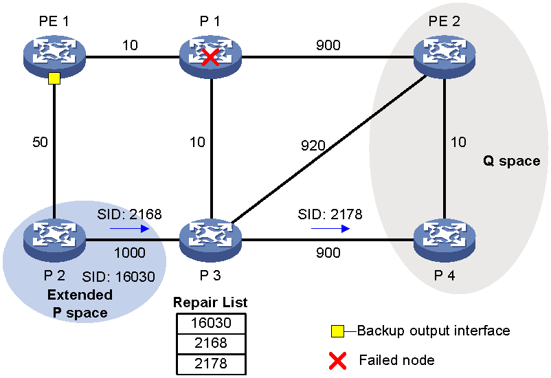
TI-LFA FRR calculates the backup path as follows:
1. Calculates the extended P space: P 2.
2. Calculates the Q space: PE 2 and P 4.
3. Calculates the shortest path tree that results from the convergence after a P1 failure: PE 1-P 2- P 4-PE 2.
4. Calculates the repair list: Node label of P 2 (16030), adjacency label of P 2 to P 3 (2168), and adjacency label of P 3 to P 4 (2178), as shown in Figure 30.
5. Calculates the backup output interface: Output interface to the next hop after the link from PE 1 to P 1 fails, that is, the interface that connects PE 1 to P 2.
TI-LFA FRR forwarding process
After TI-LFA FRR finishes backup path calculation, traffic will be switched to the backup path in response to a primary path failure.
As shown in Figure 31, P 2 is a P node and P 4 is a Q node. When the next hop on the primary path (P 1) fails, TI-LFA FRR switches the traffic to the backup path. The following are the detailed steps:
1. PE 1 encapsulates a label stack to a packet according to the repair list. The labels, from the outmost to inmost, are as follows:
¡ Node label of P node P 2 (16030), which equals the SRGB base value of P 2 plus the SID index value of P 2.
¡ Adjacency labels from P node P2 to Q node P 4, which are 2168 and 2178.
¡ The destination's node label 16010, which equals the SRGB base value of Q node P 4 plus the SID index value of destination node PE 2.
¡P 2 receives the packet, searches for a label forwarding entry based on the outmost label, pops label 2168, and forwards the packet to P 3.
2. P 3 receives the packet, searches for a label forwarding entry based on the outmost label, pops label 2178, and forwards the packet to P 4.
3. P 4 receives the packet, and searches for a label forwarding entry based on the outmost label. Because the outgoing label is 16010 and the next hop is PE 2, P 4 encapsulates 16010 as the outmost label and forwards the packet to PE 2.
Figure 31 TI-LFA FRR backup path forwarding flowchart
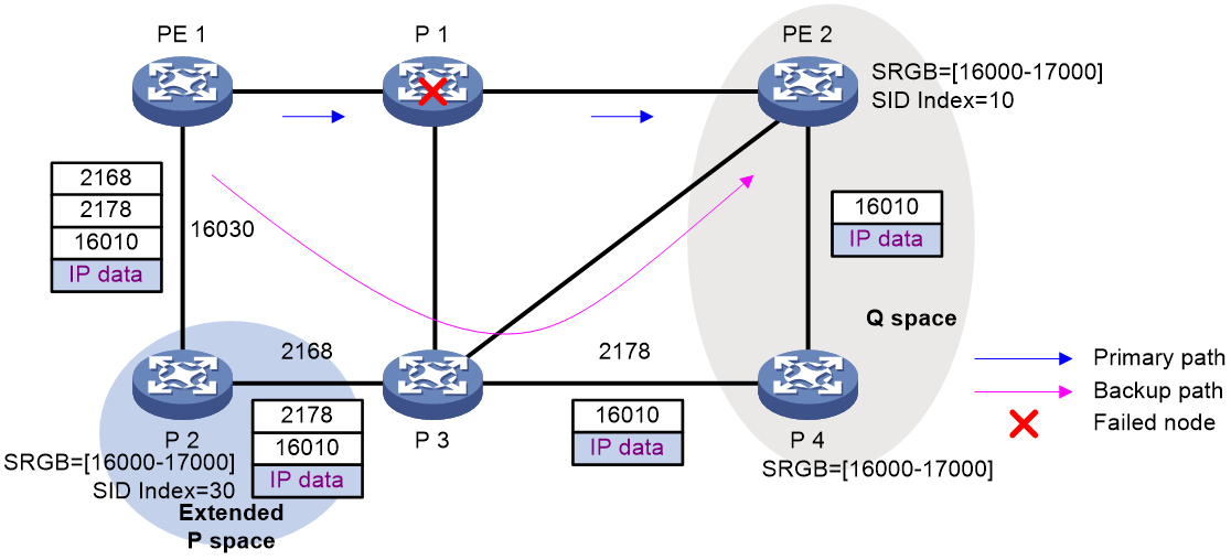
Microloop avoidance after a network failure
As shown in figure Figure 32, Device C switches traffic to the backup path calculated by TI-LFA when Device B fails.
With microloop avoidance disabled, Device A might switch traffic to the backup path upon route convergence while Device D and Device F are still performing route convergence and forwarding traffic along the original path. This situation results in a loop that will exist until Device D and Device F finish route convergence.
With microloop avoidance enabled, Device A switches traffic to the backup path calculated by TI-LFA when Device B fails. Then, Device A waits for Device D and Device F to finish route convergence before starting route convergence. After Device A also finishes route convergence, Device A continues to forward traffic on the post-convergence path. This mechanism helps avoid microloops.
Figure 32 Diagram for microloop avoidance after a network failure
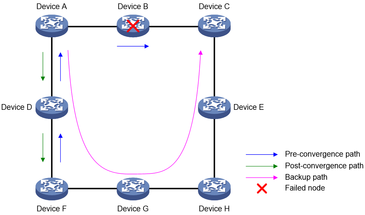
Microloop avoidance after a failure recovery
As shown in Figure 33, before the link fault between Device B and Device C is resolved, traffic is forwarded along the backup path. When the link fault between Device B and Device C recovers, if Device A converges before Device B, Device A will forward the traffic to Device B. However, if Device B has not converged and continues to forward along the backup path, a loop will form between Device A and Device B.
SR microloop avoidance can resolve this issue. After the link recovers, SR microloop avoidance automatically calculates the optimal path from Device A to Device C and forwards traffic along the path. To forward a packet along the newly calculated path, Device A adds, for example, the adjacency SID from Device B to Device C, to the packet and then sends the packet to Device B. Then, Device B forwards the packet to Device C based on the path information.
Upon expiration of the microloop avoidance RIB-update-delay timer and completion of route convergence on Device B, Device A does not add path information to packets anymore. It will forward packets to Device C as usual.
Figure 33 Microloop avoidance after a failure recovery
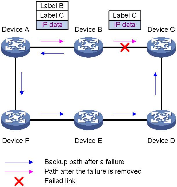
Feature control commands
Before you configure the TI-LFA FRR feature, complete the following tasks:
· Use segment-routing mpls in the IS-IS IPv4 unicast address family view or OSPF view to enable the MPLS-based SR feature.
· Use fast-reroute lfa in IS-IS IPv4 unicast address family view or OSPF view to enable LFA fast reroute, which is a prerequisite for enabling the TI-LFA fast reroute.
The following table shows the control commands for TI-LFA FRR for IS-IS and OSPF:
|
Task |
Command |
|
Enable TI-LFA FRR for IS-IS. |
fast-reroute ti-lfa (IS-IS IPv4 unicast address family view) |
|
Enable TI-LFA FRR for OSPF. |
fast-reroute ti-lfa (OSPF view) |
The following table shows the control commands for microloop avoidance:
|
Task |
Command |
|
Enable FRR microloop avoidance. |
fast-reroute microloop-avoidance enable (IS-IS IPv4 unicast address family view/OSPF view) |
|
Enable SR microloop avoidance. |
segment-routing microloop-avoidance enable (IS-IS IPv4 unicast address family view/OSPF view) |
Example: Configuring IS-IS TI-LFA FRR and microloop avoidance in an SR-MPLS network
Network configuration
As shown in Figure 34, complete the following tasks to implement TI-LFA FRR:
· Configure IS-IS on Device A, Device B, Device C, and Device D to achieve network level connectivity.
· Configure IS-IS SR on Device A, Device B, Device C, and Device D.
· Configure TI-LFA FRR to remove the loop on Link B and to implement fast traffic switchover to Link B when Link A fails.
Network diagram
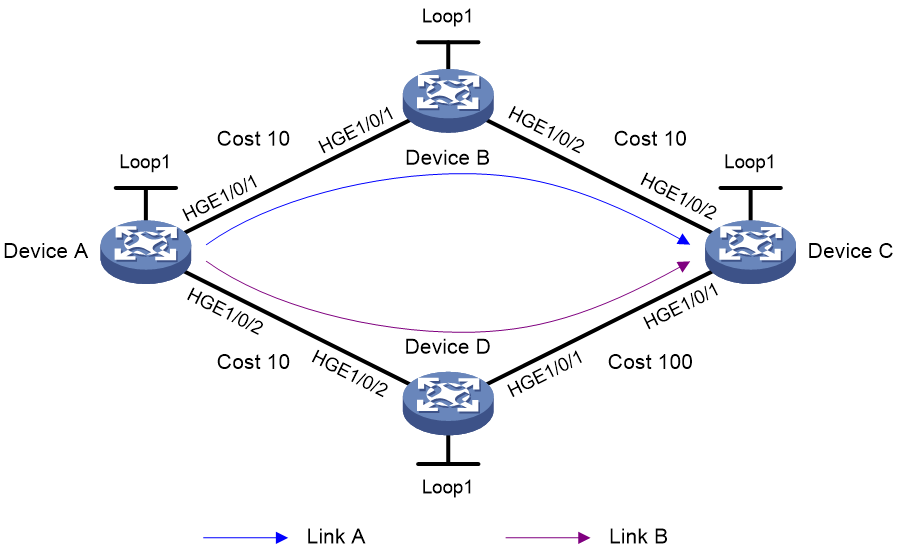
|
Device |
Interface |
IP address |
Device |
Interface |
IP address |
|
Device A |
Loop1 |
1.1.1.1/32 |
Device B |
Loop1 |
2.2.2.2/32 |
|
|
HGE1/0/1 |
12.12.12.1/24 |
|
HGE1/0/1 |
12.12.12.2/24 |
|
|
HGE1/0/2 |
14.14.14.1/24 |
|
HGE1/0/2 |
23.23.23.1/24 |
|
Device C |
Loop1 |
3.3.3.3/24 |
Device D |
Loop1 |
4.4.4.4/24 |
|
|
HGE1/0/1 |
34.34.34.1/24 |
|
HGE1/0/1 |
34.34.34.2/24 |
|
|
HGE1/0/2 |
23.23.23.2/24 |
|
HGE1/0/2 |
14.14.14.2/24 |
Procedures
1. Configure IP addresses and subnet masks for interfaces as shown in Figure 34. (Details not shown.)
2. Configure Device A:
# Configure IS-IS to implement Layer 3 connectivity, and set the IS-IS cost style to wide.
<DeviceA> system-view
[DeviceA] isis 1
[DeviceA-isis-1] network-entity 00.0000.0000.0001.00
[DeviceA-isis-1] cost-style wide
[DeviceA-isis-1] address-family ipv4
[DeviceA-isis-1-ipv4] quit
[DeviceA-isis-1] quit
[DeviceA] interface hundredgige 1/0/1
[DeviceA-HundredGigE1/0/1] isis enable 1
[DeviceA-HundredGigE1/0/1] isis cost 10
[DeviceA-HundredGigE1/0/1] quit
[DeviceA] interface hundredgige 1/0/2
[DeviceA-HundredGigE1/0/2] isis enable 1
[DeviceA-HundredGigE1/0/2] isis cost 10
[DeviceA-HundredGigE1/0/2] quit
[DeviceA] interface loopback 1
[DeviceA-LoopBack1] isis enable 1
[DeviceA-LoopBack1] quit
# Configure MPLS TE.
[DeviceA] mpls lsr-id 1.1.1.1
[DeviceA] mpls te
[DeviceA-te] quit
[DeviceA] interface hundredgige 1/0/1
[DeviceA-HundredGigE1/0/1] mpls enable
[DeviceA-HundredGigE1/0/1] mpls te enable
[DeviceA-HundredGigE1/0/1] quit
[DeviceA] interface hundredgige 1/0/2
[DeviceA-HundredGigE1/0/2] mpls enable
[DeviceA-HundredGigE1/0/2] mpls te enable
[DeviceA-HundredGigE1/0/2] quit
# Enable IS-IS SR and SR-MPLS adjacency SID allocation.
[DeviceA] isis 1
[DeviceA-isis-1] address-family ipv4
[DeviceA-isis-1-ipv4] segment-routing mpls
[DeviceA-isis-1-ipv4] segment-routing adjacency enable
[DeviceA-isis-1-ipv4] quit
[DeviceA-isis-1] quit
# Configure an IS-IS prefix SID index.
[DeviceA] interface loopback 1
[DeviceA-LoopBack1] isis prefix-sid index 10
[DeviceA-LoopBack1] quit
# Configure IS-IS TI-LFA FRR.
[DeviceA] isis 1
[DeviceA-isis-1] address-family ipv4
[DeviceA-isis-1-ipv4] fast-reroute lfa
[DeviceA-isis-1-ipv4] fast-reroute ti-lfa
[DeviceA-isis-1-ipv4] fast-reroute microloop-avoidance enable
[DeviceA-isis-1-ipv4] segment-routing microloop-avoidance enable
[DeviceA-isis-1-ipv4] quit
[DeviceA-isis-1] quit
3. Configure Device B:
# Configure IS-IS to implement Layer 3 connectivity, and set the IS-IS cost style to wide.
<DeviceB> system-view
[DeviceB] isis 1
[DeviceB-isis-1] network-entity 00.0000.0000.0002.00
[DeviceB-isis-1] cost-style wide
[DeviceB-isis-1] address-family ipv4
[DeviceB-isis-1-ipv4] quit
[DeviceB-isis-1] quit
[DeviceB] interface hundredgige 1/0/1
[DeviceB-HundredGigE1/0/1] isis enable 1
[DeviceB-HundredGigE1/0/1] isis cost 10
[DeviceB-HundredGigE1/0/1] quit
[DeviceB] interface hundredgige 1/0/2
[DeviceB-HundredGigE1/0/2] isis enable 1
[DeviceB-HundredGigE1/0/2] isis cost 10
[DeviceB-HundredGigE1/0/2] quit
[DeviceB] interface loopback 1
[DeviceB-LoopBack1] isis enable 1
[DeviceB-LoopBack1] quit
# Configure MPLS TE.
[DeviceB] mpls lsr-id 2.2.2.2
[DeviceB] mpls te
[DeviceB-te] quit
[DeviceB] interface hundredgige 1/0/1
[DeviceB-HundredGigE1/0/1] mpls enable
[DeviceB-HundredGigE1/0/1] mpls te enable
[DeviceB-HundredGigE1/0/1] quit
[DeviceB] interface hundredgige 1/0/2
[DeviceB-HundredGigE1/0/2] mpls enable
[DeviceB-HundredGigE1/0/2] mpls te enable
[DeviceB-HundredGigE1/0/2] quit
# Enable IS-IS SR and SR-MPLS adjacency SID allocation.
[DeviceB] isis 1
[DeviceB-isis-1] address-family ipv4
[DeviceB-isis-1-ipv4] segment-routing mpls
[DeviceB-isis-1-ipv4] segment-routing adjacency enable
[DeviceB-isis-1-ipv4] quit
[DeviceB-isis-1] quit
# Configure an IS-IS prefix SID.
[DeviceB] interface loopback 1
[DeviceB-LoopBack1] isis prefix-sid index 20
[DeviceB-LoopBack1] quit
# Configure IS-IS TI-LFA FRR.
[DeviceB] isis 1
[DeviceB-isis-1] address-family ipv4
[DeviceB-isis-1-ipv4] fast-reroute lfa
[DeviceB-isis-1-ipv4] fast-reroute ti-lfa
[DeviceB-isis-1-ipv4] fast-reroute microloop-avoidance enable
[DeviceB-isis-1-ipv4] segment-routing microloop-avoidance enable
[DeviceB-isis-1-ipv4] quit
[DeviceB-isis-1] quit
4. Configure Device C:
# Configure IS-IS to implement Layer 3 connectivity, and set the IS-IS cost style to wide.
<DeviceC> system-view
[DeviceC] isis 1
[DeviceC-isis-1] network-entity 00.0000.0000.0003.00
[DeviceC-isis-1] cost-style wide
[DeviceC-isis-1] address-family ipv4
[DeviceC-isis-1-ipv4] quit
[DeviceC-isis-1] quit
[DeviceC] interface hundredgige 1/0/1
[DeviceC-HundredGigE1/0/1] isis enable 1
[DeviceC-HundredGigE1/0/1] isis cost 100
[DeviceC-HundredGigE1/0/1] quit
[DeviceC] interface hundredgige 1/0/2
[DeviceC-HundredGigE1/0/2] isis enable 1
[DeviceC-HundredGigE1/0/2] isis cost 10
[DeviceC-HundredGigE1/0/2] quit
[DeviceC] interface loopback 1
[DeviceC-LoopBack1] isis enable 1
[DeviceC-LoopBack1] quit
# Configure MPLS TE.
[DeviceC] mpls lsr-id 3.3.3.3
[DeviceC] mpls te
[DeviceC-te] quit
[DeviceC] interface hundredgige 1/0/1
[DeviceC-HundredGigE1/0/1] mpls enable
[DeviceC-HundredGigE1/0/1] mpls te enable
[DeviceC-HundredGigE1/0/1] quit
[DeviceC] interface hundredgige 1/0/2
[DeviceC-HundredGigE1/0/2] mpls enable
[DeviceC-HundredGigE1/0/2] mpls te enable
[DeviceC-HundredGigE1/0/2] quit
# Enable IS-IS SR and SR-MPLS adjacency SID allocation.
[DeviceC] isis 1
[DeviceC-isis-1] address-family ipv4
[DeviceC-isis-1-ipv4] segment-routing mpls
[DeviceC-isis-1-ipv4] segment-routing adjacency enable
[DeviceC-isis-1-ipv4] quit
[DeviceC-isis-1] quit
# Configure an IS-IS prefix SID index.
[DeviceC] interface loopback 1
[DeviceC-LoopBack1] isis prefix-sid index 30
[DeviceC-LoopBack1] quit
# Configure IS-IS TI-LFA FRR.
[DeviceC] isis 1
[DeviceC-isis-1] address-family ipv4
[DeviceC-isis-1-ipv4] fast-reroute lfa
[DeviceC-isis-1-ipv4] fast-reroute ti-lfa
[DeviceC-isis-1-ipv4] fast-reroute microloop-avoidance enable
[DeviceC-isis-1-ipv4] segment-routing microloop-avoidance enable
[DeviceC-isis-1-ipv4] quit
[DeviceC-isis-1] quit
5. Configure Device D:
# Configure IS-IS to implement Layer 3 connectivity, and set the IS-IS cost style to wide.
<DeviceD> system-view
[DeviceD] isis 1
[DeviceD-isis-1] network-entity 00.0000.0000.0004.00
[DeviceD-isis-1] cost-style wide
[DeviceD-isis-1] address-family ipv4
[DeviceD-isis-1-ipv4] quit
[DeviceD-isis-1] quit
[DeviceD] interface hundredgige 1/0/1
[DeviceD-HundredGigE1/0/1] isis enable 1
[DeviceD-HundredGigE1/0/1] isis cost 100
[DeviceD-HundredGigE1/0/1] quit
[DeviceD] interface hundredgige 1/0/2
[DeviceD-HundredGigE1/0/2] isis enable 1
[DeviceD-HundredGigE1/0/2] isis cost 10
[DeviceD-HundredGigE1/0/2] quit
[DeviceD] interface loopback 1
[DeviceD-LoopBack1] isis enable 1
[DeviceD-LoopBack1] quit
# Configure MPLS TE.
[DeviceD] mpls lsr-id 4.4.4.4
[DeviceD] mpls te
[DeviceD-te] quit
[DeviceD] interface hundredgige 1/0/1
[DeviceD-HundredGigE1/0/1] mpls enable
[DeviceD-HundredGigE1/0/1] mpls te enable
[DeviceD-HundredGigE1/0/1] quit
[DeviceD] interface hundredgige 1/0/2
[DeviceD-HundredGigE1/0/2] mpls enable
[DeviceD-HundredGigE1/0/2] mpls te enable
[DeviceD-HundredGigE1/0/2] quit
# Enable IS-IS SR and SR-MPLS adjacency SID allocation.
[DeviceD] isis 1
[DeviceD-isis-1] address-family ipv4
[DeviceD-isis-1-ipv4] segment-routing mpls
[DeviceD-isis-1-ipv4] segment-routing adjacency enable
[DeviceD-isis-1-ipv4] quit
[DeviceD-isis-1] quit
# Configure an IS-IS prefix SID index.
[DeviceD] interface loopback 1
[DeviceD-LoopBack1] isis prefix-sid index 40
[DeviceD-LoopBack1] quit
# Configure IS-IS TI-LFA FRR.
[DeviceD] isis 1
[DeviceD-isis-1] address-family ipv4
[DeviceD-isis-1-ipv4] fast-reroute lfa
[DeviceD-isis-1-ipv4] fast-reroute ti-lfa
[DeviceD-isis-1-ipv4] fast-reroute microloop-avoidance enable
[DeviceD-isis-1-ipv4] segment-routing microloop-avoidance enable
[DeviceD-isis-1-ipv4] quit
[DeviceD-isis-1] quit
Verifying the configuration
1. Display the configuration:
# Display route 3.3.3.3/32 on Device A. The output shows that the TI-LFA backup next hop is an interface IP address on Device D.
[DeviceA] display isis route ipv4 3.3.3.3 32 verbose level-1 1
Route information for IS-IS(1)
-----------------------------
Level-1 IPv4 Forwarding Table
-----------------------------
IPv4 Dest : 3.3.3.3/32 Int. Cost : 10 Ext. Cost : NULL
Admin Tag : - Src Count : 1 Flag : R/L/-
InLabel : 16020 InLabel Flag: -/N/-/-/-/-
NextHop : Interface : ExitIndex :
12.12.12.2 HGE1/0/1 0x00000103
Nib ID : 0x14000005 OutLabel : 16020 OutLabelFlag: I
LabelSrc : SR
TI-LFA:
Interface : HGE1/0/2
BkNextHop : 14.14.14.2 LsIndex : 0x00000002
Backup label stack(top->bottom): {16030, 2175}
Route label: 16020
Flags: D-Direct, R-Added to Rib, L-Advertised in LSPs, U-Up/Down Bit Set
InLabel flags: R-Readvertisement, N-Node SID, P-no PHP
E-Explicit null, V-Value, L-Local
OutLabelFlags: E-Explicit null, I-Implicit null, N-Normal, P-SR label prefer
2. Perform traffic switchover:
# Display the outbound traffic rate statistics for all interfaces. The output shows that traffic is forwarded over link A when link A is operating correctly.
[DeviceA] display counters rate outbound interface
Usage: Bandwidth utilization in percentage
Interface Usage (%) Total (pps) Broadcast (pps) Multicast (pps)
HGE1/0/1 12 8444864 -- --
HGE1/0/2 0 -- --
Overflow: More than 14 digits.
--: Not supported.
# Display the outbound traffic rate statistics for all interfaces. The output shows that when outbound interface HGE1/0/1 of Device A on link A is shut down, traffic is switched to backup link link B and no packet loss occurs during the link switchover process.
[DeviceA] display counters rate outbound interface
Usage: Bandwidth utilization in percentage
Interface Usage (%) Total (pps) Broadcast (pps) Multicast (pps)
HGE1/0/1 0 0 -- --
HGE1/0/2 11 8446391 -- --
Overflow: More than 14 digits.
--: Not supported.
# Verify that when a large number of IPv4 routes exist in the network, zero packet loss occurs during traffic switchover from link A to link B. However, when traffic switches back from link B to link A, millisecond-level packet loss occurs.
Zero packet loss technology in an SRv6 network
Topology-Independent Loop-Free Alternate Fast Re-Route (TI-LFA FRR)
Topology-Independent Loop-Free Alternate Fast Re-Route (TI-LFA FRR) provides link and node protection for SRv6 tunnels. When a link or node fails, TI-LFA FRR switches the traffic to the backup path to ensure continuous data forwarding. TI-LFA FRR supports one primary link and one backup link.
Feature overview
Technical background
As shown in Figure 35, node A sends data packets to node F. When the link between node B and node E fails, node B forwards the data packets to node C. The cost of the link between node C and node D is 100 (which is greater than the cost of the link between node C and node D) and the routes on node C have not converged. As a result, node C determines that the next hop of the optimal path to reach node F is node B. Then, node C forwards the data packets back to node B, which causes a loop.
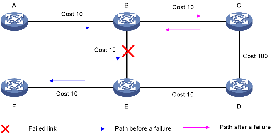
To resolve this issue, deploy TI-FLA on the SRv6 network. As shown in Figure 36, when the link between node B and node E fails, node B uses the backup path calculated by TI-LFA to forward the data packets along the B->C->D->E path.

TI-LFA FRR concepts
· P space—Use the source node of the protected link as the root to establish a shortest path tree. All nodes that are reachable from the source node without passing the protected link form the P space. Nodes in the P space are called P nodes.
· Extended P space—Use the source node of the protected link and its neighbors as the roots to establish shortest path trees. All nodes that are reachable from the source node or one of its neighbors without passing the protected link form the extended P space. The P space is a subset of the extended P space.
· Q space—Use the destination node of the protected link as the root to establish a reverse shortest path tree. All nodes that are reachable from the root node without passing the protected link form the Q space. Nodes in the Q space are called Q nodes.
· Repair list—A constraint path used to indicate how a P node reaches a Q node when the P space and Q space do not have common nodes. The repair list contains the following SRv6 SIDs:
¡ SRv6 SIDs of P nodes.
¡ SRv6 SIDs from P nodes to nearest Q nodes.
TI-LFA FRR path calculation
As shown in Figure 37, PE 1 is the source node. P 1 is the faulty node. PE 2 is the destination node. The numbers on links represent the link costs. A data flow traverses PE 1, P 1, and PE 2. To protect data against P 1 failure, TI-LFA FRR calculates the extended P space, Q space, shortest path tree converged after P 1 fails, repair list, and backup output interface, and creates the backup forwarding entry.
TI-LFA FRR calculates the backup path by using the following steps:
1. Calculates the extended P space: P 2.
2. Calculates the Q space: PE 2 and P 4.
3. Calculates the shortest path tree converged after P 1 fails: PE 1 --> P 2 --> P 4 --> PE 2.
4. Calculates the repair list: End.X SID C of the link between P 2 and P 3 and End.X SID D of the link between P 3 and P 4.
5. Calculates the backup output interface: The output interface to the next hop after the link from PE 1 to P1 fails.
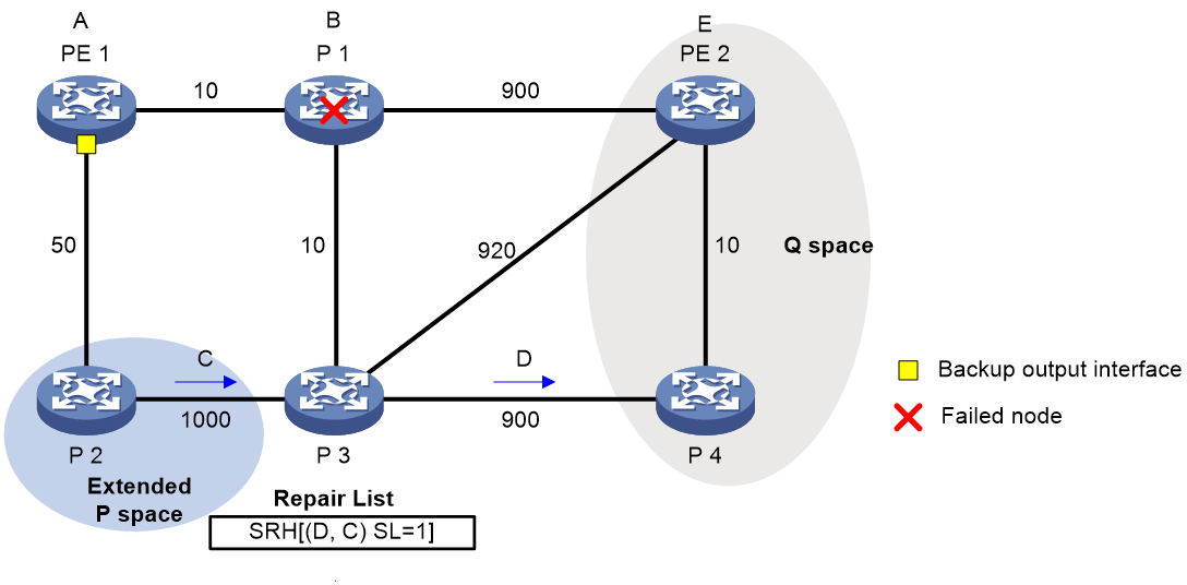
TI-LFA FRR forwarding process
After TI-LFA FRR finishes backup path calculation, traffic will be switched to the backup path in response to a primary path failure.
As shown in Figure 38, P 2 is a P node and P 4 is a Q node. When the next hop on the primary path (P 1) fails, TI-LFA FRR switches the traffic to the backup path. The following are the detailed steps:
1. PE 1 looks up the IPv6 routing table for the destination IPv6 address of a packet and finds that the next hop is P 2. PE 1 encapsulates the packet according to the repair list.
¡ Adds an SRH header. The SID list is Segment List [0]=D and Segment List [1]=C. The SIDs are arranged from the farthest node to the nearest node.
¡ Adds an outer IPv6 header. The source address is address A on source node PE 1 and the destination address is the address pointed by SL. Because the SL is 1, the destination address is C as pointed by Segment List [1].
2. After P2 receives the packet, it performs the following operations:
¡ Checks the SL value in the SRH header and decreases the value by 1.
¡ Searches for the address pointed by Segment List [0] and finds that the address is End.X SID D between P 3 and P 4.
¡ Replaces the destination address in the outer IPv6 header with End.X SID D.
¡ Obtains the output interface and next hop according to End.X SID C and forwards the encapsulated packet to P 3.
3. After P3 receives the packet, it performs the following operations:
¡ Checks the SL value in the SRH header and finds that the SL value is 0.
¡ Decapsulates the packet.
¡ Obtains the output interface and next hop according to End.X SID D and forwards the packet to P 4.
4. After P4 receives the packet, it searches the IP routing table for the destination IP address of the packet and forwards the packet to PE 2.
Figure 38 Data forwarding over the TI-LFA FRR backup path
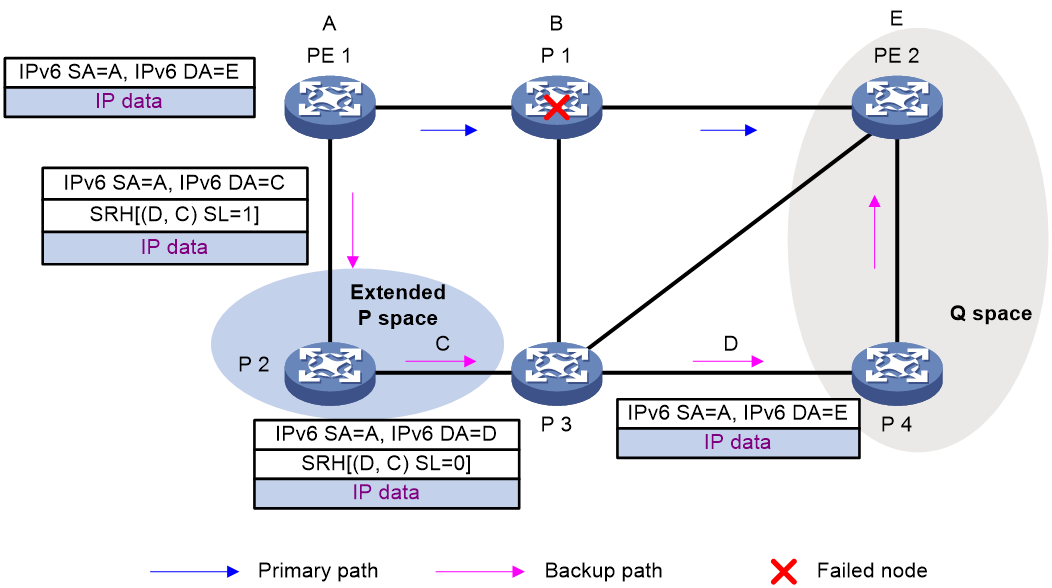
Microloop avoidance after a network failure
As shown in Figure 39, when Device B fails, traffic to Device C will be switched to the backup path calculated by TI-LFA. After Device A finishes route convergence, traffic will be switched to the post-convergence path. If Device D and Device F have not finished route convergence and still forward traffic along the pre-convergence path, a loop is formed between Device A and Device F. The loop exists until Device D and Device F finish route convergence.
FRR microloop avoidance and SR microloop avoidance can resolve this issue. After you configure TI-LFA, Device A first switches traffic to the backup path calculated by TI-LFA when Device B fails. Then, Device A waits for Device D and Device F to finish route convergence before starting route convergence. After Device A also finishes route convergence, Device A switches the traffic to the converged route.
Figure 39 Diagram for microloop avoidance after a network failure
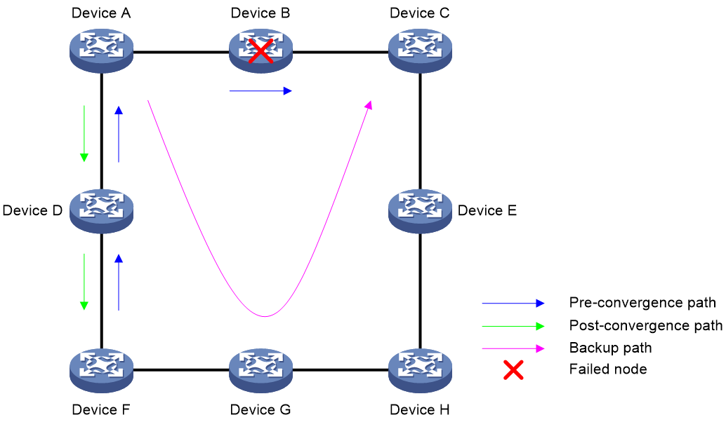
Microloop avoidance after a failure recovery
As shown in Figure 40, before the link between Device B and Device C recovers, traffic traverses along the backup path. After the link recovers, Device A forwards the traffic to Device B if Device A finishes route convergence before Device B. With route convergence unfinished, Device B still forwards the traffic along the backup path. A loop is formed between Device A and Device B.
SR microloop avoidance can resolve this issue. After the link recovers, SR microloop avoidance automatically calculates the optimal path from Device A to Device C and forwards traffic along the path. To forward a packet along the newly calculated path, Device A adds, for example, the adjacency SID from Device B to Device C, to the packet and then sends the packet to Device B. Then, Device B forwards the packet to Device C based on the path information.
Upon expiration of the microloop avoidance RIB-update-delay timer and completion of route convergence on Device B, Device A does not add path information to packets anymore. It will forward packets to Device C as usual.
Figure 40 Microloop avoidance after a failure recovery
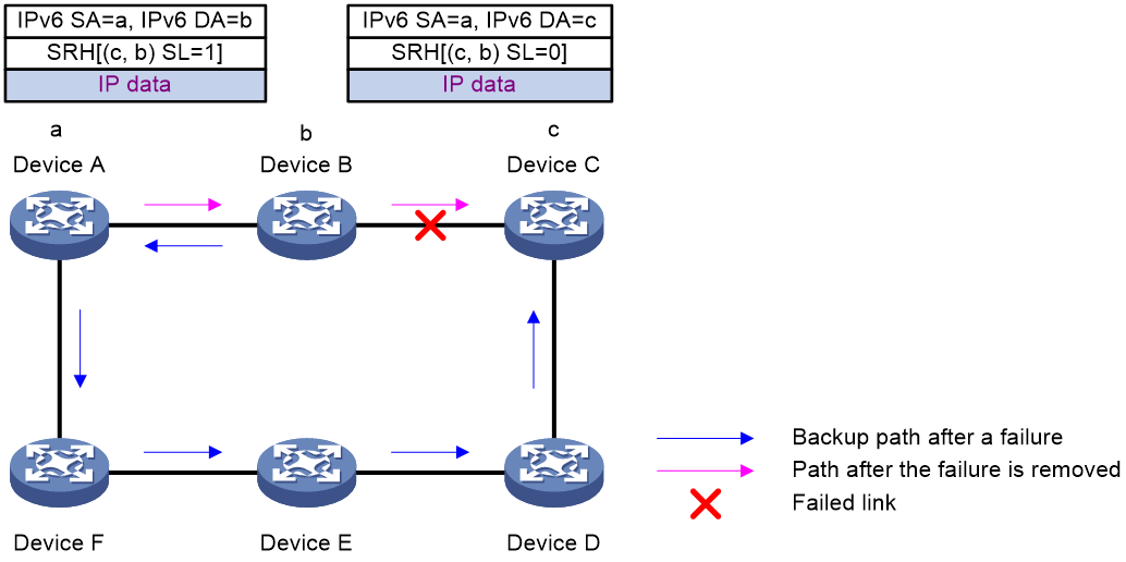
Feature control commands
For TI-LFA FRR to take effect, execute the fast-reroute ti-lfa command in IS-IS IPv6 unicast address family view or OSPFv3 view to enable LFA FRR before you configure TI-LFA FRR.
The following table shows the control commands for TI-LFA FRR for IPv6 IS-IS and OSPFv3.
|
Task |
Command |
|
Enable FRR microloop avoidance. |
fast-reroute microloop-avoidance enable (IS-IS IPv6 unicast address family view/OSPFv3 view) |
The following table shows the control commands for microloop avoidance.
|
Task |
Command |
|
Enable FRR microloop avoidance. |
fast-reroute microloop-avoidance enable (IS-IS IPv6 unicast address family view/OSPFv3 view) |
|
Enable SR microloop avoidance. |
segment-routing microloop-avoidance enable (IS-IS IPv6 unicast address family view/OSPFv3 view) |
Example: Configuring SRv6 IS-IS TI-LFA FRR and microloop avoidance
Network configuration
As shown in Figure 41, complete the following tasks to implement TI-LFA FRR:
· Configure IPv6 IS-IS on Device A, Device B, Device C, and Device D to achieve network level connectivity.
· Configure IS-IS SRv6 on Device A, Device B, Device C, and Device D.
· Configure TI-LFA FRR to remove the loop on Link B and to implement fast traffic switchover to Link B when Link A fails.

|
Device |
Interface |
IP address |
Device |
Interface |
IP address |
|
Device A |
Loop1 |
1::1/128 |
Device B |
Loop1 |
2::2/128 |
|
|
HGE1/0/1 |
2000:1::1/64 |
|
HGE1/0/1 |
2000:1::2/64 |
|
|
HGE1/0/2 |
2000:4::1/64 |
|
HGE1/0/2 |
2000:2::2/64 |
|
Device C |
Loop1 |
3::3/128 |
Device D |
Loop1 |
4::4/128 |
|
|
HGE1/0/1 |
2000:3::3/64 |
|
HGE1/0/1 |
2000:3::4/64 |
|
|
HGE1/0/2 |
2000:2::3/64 |
|
HGE1/0/2 |
2000:4::4/64 |
Major configuration steps
1. Configure IPv6 addresses and prefixes for interfaces. (Details not shown.)
2. Configure Device A:
# Configure IPv6 IS-IS to achieve network level connectivity and set the IS-IS cost style to wide.
<DeviceA> system-view
[DeviceA] isis 1
[DeviceA-isis-1] network-entity 00.0000.0000.0001.00
[DeviceA-isis-1] cost-style wide
[DeviceA-isis-1] address-family ipv6
[DeviceA-isis-1-ipv6] quit
[DeviceA-isis-1] quit
[DeviceA] interface hundredgige 1/0/1
[DeviceA-HundredGigE1/0/1] isis ipv6 enable 1
[DeviceA-HundredGigE1/0/1] isis cost 10
[DeviceA-HundredGigE1/0/1] quit
[DeviceA] interface hundredgige 1/0/2
[DeviceA-HundredGigE1/0/2] isis ipv6 enable 1
[DeviceA-HundredGigE1/0/2] isis cost 10
[DeviceA-HundredGigE1/0/2] quit
[DeviceA] interface loopback 1
[DeviceA-LoopBack1] isis ipv6 enable 1
[DeviceA-LoopBack1] quit
# Enable SRv6 and configure a locator.
[DeviceA] segment-routing ipv6
[DeviceA-segment-routing-ipv6] locator aaa ipv6-prefix 11:: 64 static 32
[DeviceA-segment-routing-ipv6-locator-aaa] quit
[DeviceA-segment-routing-ipv6] quit
# Configure IPv6 IS-IS TI-LFA FRR.
[DeviceA] isis 1
[DeviceA-isis-1] address-family ipv6
[DeviceA-isis-1-ipv6] fast-reroute lfa
[DeviceA-isis-1-ipv6] fast-reroute ti-lfa
# Configure FRR microloop avoidance.
[DeviceA-isis-1-ipv6] fast-reroute microloop-avoidance enable
# Configure SR microloop avoidance.
[DeviceA-isis-1-ipv6] segment-routing microloop-avoidance enable
[DeviceA-isis-1-ipv6] quit
[DeviceA-isis-1] quit
# Apply the locator to the IPv6 IS-IS process.
[DeviceA] isis 1
[DeviceA-isis-1] address-family ipv6
[DeviceA-isis-1-ipv6] segment-routing ipv6 locator aaa
[DeviceA-isis-1-ipv6] quit
[DeviceA-isis-1] quit
3. Configure Device B:
# Configure IPv6 IS-IS to achieve network level connectivity and set the IS-IS cost style to wide.
<DeviceB> system-view
[DeviceB] isis 1
[DeviceB-isis-1] network-entity 00.0000.0000.0002.00
[DeviceB-isis-1] cost-style wide
[DeviceB-isis-1] address-family ipv6
[DeviceB-isis-1-ipv6] quit
[DeviceB-isis-1] quit
[DeviceB] interface hundredgige 1/0/1
[DeviceB-HundredGigE1/0/1] isis ipv6 enable 1
[DeviceB-HundredGigE1/0/1] isis cost 10
[DeviceB-HundredGigE1/0/1] quit
[DeviceB] interface hundredgige 1/0/2
[DeviceB-HundredGigE1/0/2] isis ipv6 enable 1
[DeviceB-HundredGigE1/0/2] isis cost 10
[DeviceB-HundredGigE1/0/2] quit
[DeviceB] interface loopback 1
[DeviceB-LoopBack1] isis ipv6 enable 1
[DeviceB-LoopBack1] quit
# Enable SRv6 and configure a locator.
[DeviceB] segment-routing ipv6
[DeviceB-segment-routing-ipv6] locator bbb ipv6-prefix 22:: 64 static 32
[DeviceB-segment-routing-ipv6-locator-bbb] quit
[DeviceB-segment-routing-ipv6] quit
# Configure IPv6 IS-IS TI-LFA FRR.
[DeviceB] isis 1
[DeviceB-isis-1] address-family ipv6
[DeviceB-isis-1-ipv6] fast-reroute lfa
[DeviceB-isis-1-ipv6] fast-reroute ti-lfa
# Apply the locator to the IPv6 IS-IS process.
[DeviceB-isis-1-ipv6] segment-routing ipv6 locator bbb
[DeviceB-isis-1-ipv6] quit
[DeviceB-isis-1] quit
4. Configure Device C:
# Configure IPv6 IS-IS to achieve network level connectivity and set the IS-IS cost style to wide.
<DeviceC> system-view
[DeviceC] isis 1
[DeviceC-isis-1] network-entity 00.0000.0000.0003.00
[DeviceC-isis-1] cost-style wide
[DeviceC-isis-1] address-family ipv6
[DeviceC-isis-1-ipv6] quit
[DeviceC-isis-1] quit
[DeviceC] interface hundredgige 1/0/1
[DeviceC-HundredGigE1/0/1] isis ipv6 enable 1
[DeviceC-HundredGigE1/0/1] isis cost 100
[DeviceC-HundredGigE1/0/1] quit
[DeviceC] interface hundredgige 1/0/2
[DeviceC-HundredGigE1/0/2] isis ipv6 enable 1
[DeviceC-HundredGigE1/0/2] isis cost 10
[DeviceC-HundredGigE1/0/2] quit
[DeviceC] interface loopback 1
[DeviceC-LoopBack1] isis ipv6 enable 1
[DeviceC-LoopBack1] quit
# Enable SRv6 and configure a locator.
[DeviceC] segment-routing ipv6
[DeviceC-segment-routing-ipv6] locator ccc ipv6-prefix 33:: 64 static 32
[DeviceC-segment-routing-ipv6-locator-ccc] quit
[DeviceC-segment-routing-ipv6] quit
# Configure IPv6 IS-IS TI-LFA FRR.
[DeviceC] isis 1
[DeviceC-isis-1] address-family ipv6
[DeviceC-isis-1-ipv6] fast-reroute lfa
[DeviceC-isis-1-ipv6] fast-reroute ti-lfa
# Apply the locator to the IPv6 IS-IS process.
[DeviceC-isis-1-ipv6] segment-routing ipv6 locator ccc
[DeviceC-isis-1-ipv6] quit
[DeviceC-isis-1] quit
5. Configure Device D:
# Configure IPv6 IS-IS to achieve network level connectivity and set the IS-IS cost style to wide.
<DeviceD> system-view
[DeviceD] isis 1
[DeviceD-isis-1] network-entity 00.0000.0000.0004.00
[DeviceD-isis-1] cost-style wide
[DeviceD-isis-1] address-family ipv6
[DeviceD-isis-1-ipv6] quit
[DeviceD-isis-1] quit
[DeviceD] interface hundredgige 1/0/1
[DeviceD-HundredGigE1/0/1] isis ipv6 enable 1
[DeviceD-HundredGigE1/0/1] isis cost 100
[DeviceD-HundredGigE1/0/1] quit
[DeviceD] interface hundredgige 1/0/2
[DeviceD-HundredGigE1/0/2] isis ipv6 enable 1
[DeviceD-HundredGigE1/0/2] isis cost 10
[DeviceD-HundredGigE1/0/2] quit
[DeviceD] interface loopback 1
[DeviceD-LoopBack1] isis ipv6 enable 1
[DeviceD-LoopBack1] quit
# Enable SRv6 and configure a locator.
[DeviceD] segment-routing ipv6
[DeviceD-segment-routing-ipv6] locator ddd ipv6-prefix 44:: 64 static 32
[DeviceD-segment-routing-ipv6-locator-ddd] quit
[DeviceD-segment-routing-ipv6] quit
# Configure IPv6 IS-IS TI-LFA FRR.
[DeviceD] isis 1
[DeviceD-isis-1] address-family ipv6
[DeviceD-isis-1-ipv6] fast-reroute lfa
[DeviceD-isis-1-ipv6] fast-reroute ti-lfa
# Apply the locator to the IPv6 IS-IS process.
[DeviceD-isis-1-ipv6] segment-routing ipv6 locator ddd
[DeviceD-isis-1-ipv6] quit
[DeviceD-isis-1] quit
Verifying the configuration
# Display IPv6 IS-IS routing information for 3::3/128.
[DeviceA] display isis route ipv6 3::3 128 verbose
Route information for IS-IS(1)
------------------------------
Level-1 IPv6 forwarding table
-----------------------------
IPv6 dest : 3::3/128
Flag : R/L/- Cost : 20
Admin tag : - Src count : 2
Nexthop : FE80::4449:7CFF:FEE0:206
Interface : HGE1/0/1
TI-LFA:
Interface : HGE1/0/2
BkNextHop : FE80::4449:91FF:FE42:407
LsIndex : 0x80000001
Backup label stack(top->bottom): {44::1:0:1}
Nib ID : 0x24000006
Flags: D-Direct, R-Added to Rib, L-Advertised in LSPs, U-Up/Down Bit Set
# Verify that zero packet loss can be implemented when only SR microloop avoidance is configured and no other routes exist in the network.
# Display the outbound traffic rate statistics for all interfaces. The output shows that IPv6 traffic is forwarded over link A when link A is operating correctly.
[DeviceA] display counters rate outbound interface
Usage: Bandwidth utilization in percentage
Interface Usage (%) Total (pps) Broadcast (pps) Multicast (pps)
HGE1/0/1 11 8447434 -- --
HGE1/0/2 0 -- --
Overflow: More than 14 digits.
--: Not supported.
# Display the outbound traffic rate statistics for all interfaces. The output shows that when outbound interface HGE1/0/1 of Device A on link A is shut down, traffic is switched to backup link link B and no packet loss occurs during the link switchover process.
[DeviceA] display counters rate outbound interface
Usage: Bandwidth utilization in percentage
Interface Usage (%) Total (pps) Broadcast (pps) Multicast (pps)
HGE1/0/1 0 0 -- --
HGE1/0/2 12 8445450 -- --
Overflow: More than 14 digits.
--: Not supported.
# Verify that zero packet loss in microloop avoidance after a network failure and millisecond-level packet loss in microloop avoidance after a failure recovery can be implemented when only SR microloop avoidance is configured and other routes exist in the network.
# Verify that millisecond-level packet loss can be implemented in both microloop avoidance after a network failure and microloop avoidance after a failure recovery can be implemented when the following conditions are met:
· Both SR microloop avoidance and FRR microloop avoidance are configured.
· Other routes exist in the network.
SRv6 TE policy egress protection
Feature overview
About this feature
This feature provides egress node protection in IP L3VPN over SRv6, EVPN L3VPN over SRv6, EVPN VPLS over SRv6, EVPN VPWS over SRv6, or IP public network over SRv6 networks where the public tunnel is an SRv6 TE policy tunnel.
SRv6 TE policy egress protection applies only to the dual homing scenario. To implement SRv6 TE policy egress protection, the egress node and the egress node's protection node must have the same forwarding entries.
SRv6 TE policy egress protection is not supported in EVPN VPLS over SRv6 and EVPN VPWS over SRv6 networks if dual homing is configured in the networks and the redundancy mode is single-active.
As shown in Figure 42, deploy an SRv6 TE policy between PE 1 and PE 3. PE 3 is the egress node (endpoint node) of the SRv6 TE policy. To provide assured forwarding services, configure PE 4 to protect PE 3.
Figure 42 SRv6 TE policy egress protection
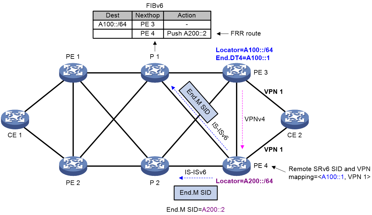
End.M SID
In SRv6 TE policy egress protection, an End.M SID is used to protect the SRv6 SIDs in a specific locator. If an SRv6 SID advertised by the remote device (PE 3 in this example) is within the locator, the protection node (PE 4) uses the End.M SID to protect that SRv6 SID (remote SRv6 SID).
PE 4 takes different actions as instructed by an End.M SID in different network scenarios:
IP L3VPN/EVPN L3VPN/IP public network over SRv6 TE policy scenario
· Removes the outer IPv6 header to obtain the remote SRv6 SID from the inner packet.
· Searches the remote SRv6 SID and VPN instance/public instance mapping table to find the VPN instance/public instance mapped to the remote SRv6 SID.
· Forwards the packet by looking up the routing table of the VPN instance/public instance.
EVPN VPWS over SRv6 TE policy scenario
· Removes the outer IPv6 header to obtain the remote SRv6 SID from the inner packet.
· Searches the remote SRv6 SID and cross-connect mapping table to find the cross-connect mapped to the remote SRv6 SID.
· Forwards the packet to the AC associated with the cross-connect.
EVPN VPLS over SRv6 TE policy scenario
· Removes the outer IPv6 header to obtain the remote SRv6 SID from the inner packet.
· Searches the remote SRv6 SID and VSI mapping table to find the VSI mapped to the remote SRv6 SID.
· Forwards the packet according to the MAC address forwarding table of the VSI.
Remote SRv6 SID
As shown in Figure 42, PE 4 receives a BGP route from PE 3. If the SRv6 SID in the BGP route is within the locator protected by the End.M SID on PE 4, PE 4 regards the SRv6 SID as a remote SRv6 SID and generates a mapping between the remote SRv6 SID and the VPN instance/public instance, cross-connect, or VSI.
When the adjacency between PE 4 and PE 3 breaks, PE 4 deletes the BGP route received from PE 3. As a result, the remote SRv6 SID and VPN instance/public instance/cross-connect/VSI mapping will be deleted, resulting in packet loss. To avoid this issue, you can configure the mappings deletion delay time on PE 4 to ensure that traffic is forwarded through PE 4 before PE 1 knows the PE 3 failure and computes a new forwarding path.
Route advertisement
The route advertisement procedure is similar in IP L3VPN, EVPN L3VPN, EVPN VPWS, EVPN VPLS, or IP public network over SRv6 TE policy egress protection scenarios. The following example describes the route advertisement in an IP L3VPN over SRv6 TE policy egress protection scenario.
As shown in Figure 42, the FRR path is generated on P 1 as follows:
1. PE 4 advertises the End.M SID and the protected locator to P 1 through an IS-ISv6 route. Meanwhile, PE 4 generates a local SID entry for the End.M SID.
2. Upon receiving the route that carries the End.M SID, P 1 generates an FRR route destined for the specified locator and the action for the route is pushing the End.M SID.
On PE 4, a <remote SRv6 SID, VPN instance > mapping entry is generated as follows:
1. Upon receiving the private route from CE 2, PE 3 encapsulates the route as a VPNv4 route and sends it to PE 4. The VPNv4 route carries the SRv6 SID, RT, and RD information.
2. After PE 4 receives the VPNv4 route, it obtains the SRv6 SID and the VPN instance. Then, PE 4 performs longest matching of the SRv6 SID against the locators protected by End.M SIDs. If a match is found, PE 4 uses the SRv6 SID as a remote SRv6 SID and generates a <remote SRv6 SID, VPN instance> mapping entry.
Packet forwarding
The packet forwarding procedure is similar in IP L3VPN, EVPN L3VPN, EVPN VPWS, EVPN VPLS, or IP public network over SRv6 TE policy egress protection scenarios. The following example describes the packet forwarding in an IP L3VPN over SRv6 TE policy egress protection scenario.
Figure 43 Data forwarding in SRv6 TE policy egress protection
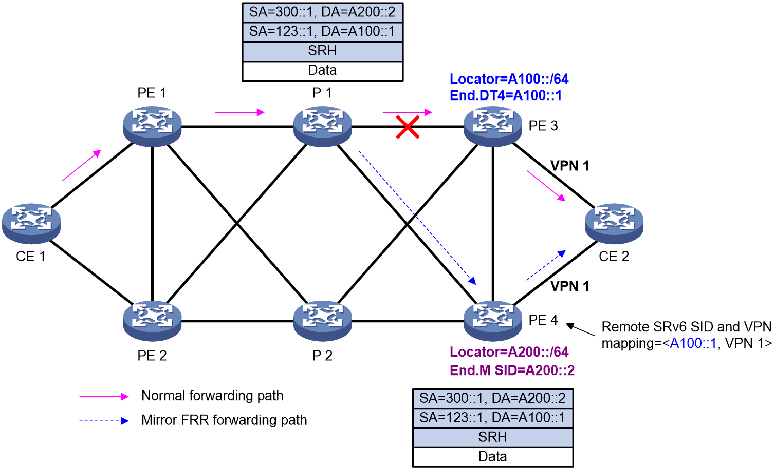
As shown in Figure 43, typically traffic is forwarded along the CE 1-PE 1-P 1-PE 3-CE 2 path. When the egress node PE 3 fails, a packet is forwarded as follows:
1. P 1 detects that its next hop (PE 3) is unreachable and thus switches traffic to the FRR path. P 1 pushes the End.M SID into the IPv6 header of the packet and forwards the packet to PE 4.
2. PE 4 parses the packet and obtains the End.M SID. PE 4 queries the local SID table and takes actions as instructed by the End.M SID:
¡ Removes the outer IPv6 header to obtain the remote SRv6 SID from the inner packet. (The remote SRv6 SID is A100::1 in this example)
¡ Searches the remote SRv6 SID and VPN instance mapping table to find the VPN instance mapped to the remote SRv6 SID. (The VPN instance is VPN 1 in this example.)
¡ Looks up the routing table of the VPN instance and forwards the packet to CE 2 according to the matching route.
Feature control commands
The following table shows the control commands for SRv6 TE policy egress protection.
|
Task |
Command |
|
Configure the opcode of End.M SIDs for a locator. |
opcode opcode end-m mirror-locator ipv6-address prefix-length (SRv6 locator view) |
|
Enable SRv6 egress node protection. |
fast-reroute mirror enable (IS-IS IPv6 unicast address family view/OSPFv3 view) |
Example: Configuring SRv6 TE policy egress protection
Network configuration
As shown in Figure 44, deploy an SRv6 TE policy in both directions between PE 1 and PE 2 to carry the L3VPN service. PE 2 is the egress node of the SRv6 TE policy. To improve the forwarding reliability, configure PE 3 to protect PE 2.
When PE 2 fails, the P device detects that the next hop of PE 2 is unreachable and disconnects the interface that connects the P device to PE 2 and traffic is forwarded by PE 3, preventing packet loss.
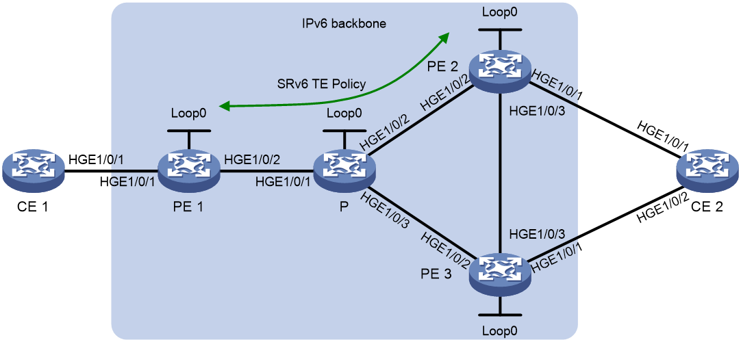
|
Device |
Interface |
IP address |
Device |
Interface |
IP address |
|
CE 1 |
HGE1/0/1 |
10.1.1.2/24 |
PE 2 |
Loop0 |
3::3/128 |
|
PE 1 |
Loop0 |
1::1/128 |
|
HGE1/0/1 |
10.2.1.1/24 |
|
|
HGE1/0/1 |
10.1.1.1/24 |
|
HGE1/0/2 |
2002::1/64 |
|
|
HGE1/0/2 |
2001::1/96 |
|
HGE1/0/3 |
2004::2/96 |
|
P |
Loop0 |
2::2/128 |
PE 3 |
Loop0 |
4::4/128 |
|
|
HGE1/0/1 |
2001::2/96 |
|
HGE1/0/1 |
10.3.1.1/24 |
|
|
HGE1/0/2 |
2002::2/64 |
|
HGE1/0/2 |
2003::1/96 |
|
|
HGE1/0/3 |
2003::2/96 |
|
HGE1/0/3 |
2004::1/96 |
|
|
|
|
CE 2 |
HGE1/0/1 |
10.2.1.2/24 |
|
|
|
|
|
HGE1/0/2 |
10.3.1.2/24 |
Prerequisites
Configure IP addresses and masks for interfaces as shown in Figure 44. (Details not shown.)
Major configuration steps
1. Configure CE 1:
# Establish an EBGP peer relationship with PE 1 and redistribute the VPN routes.
<CE1> system-view
[CE1] bgp 65410
[CE1-bgp-default] peer 10.1.1.1 as-number 100
[CE1-bgp-default] address-family ipv4 unicast
[CE1-bgp-default-ipv4] peer 10.1.1.1 enable
[CE1-bgp-default-ipv4] import-route direct
[CE1-bgp-default-ipv4] quit
[CE1-bgp-default] quit
2. Configure PE 1:
# Configure IPv6 IS-IS for backbone network connectivity.
<PE1> system-view
[PE1] isis 1
[PE1-isis-1] is-level level-1
[PE1-isis-1] cost-style wide
[PE1-isis-1] network-entity 10.1111.1111.1111.00
[PE1-isis-1] address-family ipv6 unicast
[PE1-isis-1-ipv6] quit
[PE1-isis-1] quit
[PE1] interface loopback 0
[PE1-LoopBack0] ipv6 address 1::1 128
[PE1-LoopBack0] isis ipv6 enable 1
[PE1-LoopBack0] quit
[PE1] interface hundredgige 1/0/2
[PE1-HundredGigE1/0/2] ipv6 address 2001::1 96
[PE1-HundredGigE1/0/2] isis ipv6 enable 1
[PE1-HundredGigE1/0/2] quit
# Configure a VPN instance and bind it to the CE-facing interface.
[PE1] ip vpn-instance vpn1
[PE1-vpn-instance-vpn1] route-distinguisher 100:1
[PE1-vpn-instance-vpn1] vpn-target 111:1
[PE1-vpn-instance-vpn1] quit
[PE1] interface hundredgige 1/0/1
[PE1-HundredGigE1/0/1] ip binding vpn-instance vpn1
[PE1-HundredGigE1/0/1] ip address 10.1.1.1 24
[PE1-HundredGigE1/0/1] quit
# Establish an EBGP peer relationship with the connected CE to redistribute the VPN routes.
[PE1] bgp 100
[PE1-bgp-default] router-id 1.1.1.1
[PE1-bgp-default] ip vpn-instance vpn1
[PE1-bgp-default-vpn1] peer 10.1.1.2 as-number 65410
[PE1-bgp-default-vpn1] address-family ipv4 unicast
[PE1-bgp-default-ipv4-vpn1] peer 10.1.1.2 enable
[PE1-bgp-default-ipv4-vpn1] quit
[PE1-bgp-default-vpn1] quit
# Establish MP-IBGP peer relationships with the peer PEs.
[PE1] bgp 100
[PE1-bgp-default] peer 3::3 as-number 100
[PE1-bgp-default] peer 4::4 as-number 100
[PE1-bgp-default] peer 3::3 connect-interface loopback 0
[PE1-bgp-default] peer 4::4 connect-interface loopback 0
[PE1-bgp-default] address-family vpnv4
[PE1-bgp-default-vpnv4] peer 3::3 enable
[PE1-bgp-default-vpnv4] peer 4::4 enable
[PE1-bgp-default-vpnv4] quit
[PE1-bgp-default] quit
# Configure L3VPN over SRv6 TE policy.
[PE1] segment-routing ipv6
[PE1-segment-routing-ipv6] encapsulation source-address 1::1
[PE1-segment-routing-ipv6] locator aaa ipv6-prefix 1:2::1:0 96 static 8
[PE1-segment-routing-ipv6-locator-aaa] opcode 1 end-dt4 vpn-instance vpn1
[PE1-segment-routing-ipv6-locator-aaa] quit
[PE1-segment-routing-ipv6] quit
[PE1] bgp 100
[PE1-bgp-default] address-family vpnv4
[PE1-bgp-default-vpnv4] peer 3::3 prefix-sid
[PE1-bgp-default-vpnv4] peer 4::4 prefix-sid
[PE1-bgp-default-vpnv4] quit
[PE1-bgp-default] ip vpn-instance vpn1
[PE1-bgp-default-vpn1] address-family ipv4 unicast
[PE1-bgp-default-ipv4-vpn1] segment-routing ipv6 traffic-engineering best-effort
[PE1-bgp-default-ipv4-vpn1] segment-routing ipv6 locator aaa
[PE1-bgp-default-ipv4-vpn1] quit
[PE1-bgp-default-vpn1] quit
[PE1-bgp-default] quit
[PE1] isis 1
[PE1-isis-1] address-family ipv6 unicast
[PE1-isis-1-ipv6] segment-routing ipv6 locator aaa
[PE1-isis-1-ipv6] quit
[PE1-isis-1] quit
# Configure an SRv6 TE policy.
[PE1] segment-routing ipv6
[PE1-segment-routing-ipv6] traffic-engineering
[PE1-srv6-te] srv6-policy locator aaa
[PE1-srv6-te] segment-list s1
[PE1-srv6-te-s1-s1] index 10 ipv6 100:abc:1::1
[PE1-srv6-te-s1-s1] index 20 ipv6 6:5::1:2
[PE1-srv6-te-s1-s1] quit
[PE1-srv6-te] policy p1
[PE1-srv6-te-policy-p1] binding-sid ipv6 1:2::1:2
[PE1-srv6-te-policy-p1] color 10 end-point ipv6 3::3
[PE1-srv6-te-policy-p1] forwarding ignore-last-sid enable
[PE1-srv6-te-policy-p1] candidate-paths
[PE1-srv6-te-policy-p1-path] preference 10
[PE1-srv6-te-policy-p1-path-pref-10] explicit segment-list s1
[PE1-srv6-te-policy-p1-path-pref-10] quit
[PE1-srv6-te-policy-p1-path] quit
[PE1-srv6-te-policy-p1] quit
[PE1-srv6-te] segment-list s2
[PE1-srv6-te-s2-s2] index 10 ipv6 100:abc:1::1
[PE1-srv6-te-s2-s2] index 20 ipv6 9:7::100
[PE1-srv6-te-s2-s2] quit
[PE1-srv6-te] policy p2
[PE1-srv6-te-policy-p2] binding-sid ipv6 1:2::1:2
[PE1-srv6-te-policy-p2] color 10 end-point ipv6 4::4
[PE1-srv6-te-policy-p2] forwarding ignore-last-sid enable
[PE1-srv6-te-policy-p2] candidate-paths
[PE1-srv6-te-policy-p2-path] preference 20
[PE1-srv6-te-policy-p2-path-pref-20] explicit segment-list s2
[PE1-srv6-te-policy-p2-path-pref-20] quit
[PE1-srv6-te-policy-p2-path] quit
[PE1-srv6-te-policy-p2] quit
[PE1-srv6-te] quit
[PE1-segment-routing-ipv6] quit
3. Configure the P device:
# Configure IPv6 IS-IS for backbone network connectivity.
<P> system-view
[P] isis 1
[P-isis-1] is-level level-1
[P-isis-1] cost-style wide
[P-isis-1] network-entity 10.2222.2222.2222.00
[P-isis-1] address-family ipv6 unicast
[P-isis-1-ipv6] quit
[P-isis-1] quit
[P] interface loopback 0
[P-LoopBack0] ipv6 address 2::2 128
[P-LoopBack0] isis ipv6 enable 1
[P-LoopBack0] quit
[P] interface hundredgige 1/0/1
[P-HundredGigE1/0/1] ipv6 address 2001::2 96
[P-HundredGigE1/0/1] isis ipv6 enable 1
[P-HundredGigE1/0/1] quit
[P] interface hundredgige 1/0/2
[P-HundredGigE1/0/2] ipv6 address 2002::2 96
[P-HundredGigE1/0/2] isis ipv6 enable 1
[P-HundredGigE1/0/2] quit
[P] interface hundredgige 1/0/3
[P-HundredGigE1/0/3] ipv6 address 2003::2 96
[P-HundredGigE1/0/3] isis ipv6 enable 1
[P-HundredGigE1/0/3] quit
# Configure SRv6.
[P] segment-routing ipv6
[P-segment-routing-ipv6] locator p ipv6-prefix 100:abc:1::0 96 static 8
[P-segment-routing-ipv6-locator-p] opcode 1 end
[P-segment-routing-ipv6-locator-p] quit
[P-segment-routing-ipv6] quit
[P] isis 1
[P-isis-1] address-family ipv6 unicast
[P-isis-1-ipv6] segment-routing ipv6 locator p
# Configure the FRR backup next hop information and enable egress protection.
[P-isis-1-ipv6] fast-reroute lfa level-1
[P-isis-1-ipv6] fast-reroute ti-lfa
[P-isis-1-ipv6] fast-reroute mirror enable
[P-isis-1-ipv6] fast-reroute mirror delete-delay 480
[P-isis-1-ipv6] quit
[P-isis-1] quit
4. Configure PE 2:
# Configure IPv6 IS-IS for backbone network connectivity.
<PE2> system-view
[PE2] isis 1
[PE2-isis-1] is-level level-1
[PE2-isis-1] cost-style wide
[PE2-isis-1] network-entity 10.3333.3333.3333.00
[PE2-isis-1] address-family ipv6 unicast
[PE2-isis-1-ipv6] quit
[PE2-isis-1] quit
[PE2] interface loopback 0
[PE2-LoopBack0] ipv6 address 3::3 128
[PE2-LoopBack0] isis ipv6 enable 1
[PE2-LoopBack0] quit
[PE2] interface hundredgige 1/0/2
[PE2-HundredGigE1/0/2] ipv6 address 2002::1 96
[PE2-HundredGigE1/0/2] isis ipv6 enable 1
[PE2-HundredGigE1/0/2] quit
[PE2] interface hundredgige 1/0/3
[PE2-HundredGigE1/0/3] ipv6 address 2004::2 96
[PE2-HundredGigE1/0/3] isis ipv6 enable 1
[PE2-HundredGigE1/0/3] quit
# Configure a VPN instance and bind it to the CE-facing interface.
[PE2] ip vpn-instance vpn1
[PE2-vpn-instance-vpn1] route-distinguisher 100:1
[PE2-vpn-instance-vpn1] vpn-target 111:1
[PE2-vpn-instance-vpn1] quit
[PE2] interface hundredgige 1/0/1
[PE2-HundredGigE1/0/1] ip binding vpn-instance vpn1
[PE2-HundredGigE1/0/1] ip address 10.2.1.1 24
[PE2-HundredGigE1/0/1] quit
# Establish an EBGP peer relationship with the connected CE to redistribute the VPN routes.
[PE2] bgp 100
[PE2-bgp-default] router-id 2.2.2.2
[PE2-bgp-default] ip vpn-instance vpn1
[PE2-bgp-default-vpn1] peer 10.2.1.2 as-number 65420
[PE2-bgp-default-vpn1] address-family ipv4 unicast
[PE2-bgp-default-ipv4-vpn1] peer 10.2.1.2 enable
[PE2-bgp-default-ipv4-vpn1] quit
[PE2-bgp-default-vpn1] quit
# Establish MP-IBGP peer relationships with the peer PEs.
[PE2] bgp 100
[PE2-bgp-default] peer 1::1 as-number 100
[PE2-bgp-default] peer 4::4 as-number 100
[PE2-bgp-default] peer 1::1 connect-interface loopback 0
[PE2-bgp-default] peer 4::4 connect-interface loopback 0
[PE2-bgp-default] address-family vpnv4
[PE2-bgp-default-vpnv4] peer 1::1 enable
[PE2-bgp-default-vpnv4] peer 4::4 enable
[PE2-bgp-default-vpnv4] quit
[PE2-bgp-default] quit
# Configure L3VPN over SRv6 TE policy.
[PE2] segment-routing ipv6
[PE2-segment-routing-ipv6] encapsulation source-address 3::3
[PE2-segment-routing-ipv6] locator bbb ipv6-prefix 6:5::1:0 96 static 8
[PE2-segment-routing-ipv6-locator-bbb] opcode 1 end-dt4 vpn-instance vpn1
[PE2-segment-routing-ipv6-locator-bbb] opcode 2 end
[PE2-segment-routing-ipv6-locator-bbb] quit
[PE2-segment-routing-ipv6] quit
[PE2] bgp 100
[PE2-bgp-default] address-family vpnv4
[PE2-bgp-default-vpnv4] peer 1::1 prefix-sid
[PE2-bgp-default-vpnv4] peer 4::4 prefix-sid
[PE2-bgp-default-vpnv4] quit
[PE2-bgp-default] ip vpn-instance vpn1
[PE2-bgp-default-vpn1] address-family ipv4 unicast
[PE2-bgp-default-ipv4-vpn1] segment-routing ipv6 traffic-engineering best-effort
[PE2-bgp-default-ipv4-vpn1] segment-routing ipv6 locator bbb
[PE2-bgp-default-ipv4-vpn1] quit
[PE2-bgp-default-vpn1] quit
[PE2-bgp-default] quit
[PE2] isis 1
[PE2-isis-1] address-family ipv6 unicast
[PE2-isis-1-ipv6] segment-routing ipv6 locator bbb
[PE2-isis-1-ipv6] quit
[PE2-isis-1] quit
5. Configure PE 3:
# Configure IPv6 IS-IS for backbone network connectivity.
<PE3> system-view
[PE3] isis 1
[PE3-isis-1] is-level level-1
[PE3-isis-1] cost-style wide
[PE3-isis-1] network-entity 10.4444.4444.4444.00
[PE3-isis-1] address-family ipv6 unicast
[PE3-isis-1-ipv6] quit
[PE3-isis-1] quit
[PE3] interface loopback 0
[PE3-LoopBack0] ipv6 address 4::4 128
[PE3-LoopBack0] isis ipv6 enable 1
[PE3-LoopBack0] quit
[PE3] interface hundredgige 1/0/2
[PE3-HundredGigE1/0/2] ipv6 address 2003::1 96
[PE3-HundredGigE1/0/2] isis ipv6 enable 1
[PE3-HundredGigE1/0/2] quit
[PE3] interface hundredgige 1/0/3
[PE3-HundredGigE1/0/3] ipv6 address 2004::1 96
[PE3-HundredGigE1/0/3] isis ipv6 enable 1
[PE3-HundredGigE1/0/3] quit
# Configure a VPN instance and bind it to the CE-facing interface.
[PE3] ip vpn-instance vpn1
[PE3-vpn-instance-vpn1] route-distinguisher 100:1
[PE3-vpn-instance-vpn1] vpn-target 111:1
[PE3-vpn-instance-vpn1] quit
[PE3] interface hundredgige 1/0/1
[PE3-HundredGigE1/0/1] ip binding vpn-instance vpn1
[PE3-HundredGigE1/0/1] ip address 10.3.1.1 24
[PE3-HundredGigE1/0/1] quit
# Establish an EBGP peer relationship with the connected CE to redistribute the VPN routes.
[PE3] bgp 100
[PE3-bgp-default] router-id 3.3.3.3
[PE3-bgp-default] ip vpn-instance vpn1
[PE3-bgp-default-vpn1] peer 10.3.1.2 as-number 65420
[PE3-bgp-default-vpn1] address-family ipv4 unicast
[PE3-bgp-default-ipv4-vpn1] peer 10.3.1.2 enable
[PE3-bgp-default-ipv4-vpn1] quit
[PE3-bgp-default-vpn1] quit
# Establish MP-IBGP peer relationships with the peer PEs.
[PE3] bgp 100
[PE3-bgp-default] peer 1::1 as-number 100
[PE3-bgp-default] peer 3::3 as-number 100
[PE3-bgp-default] peer 1::1 connect-interface loopback 0
[PE3-bgp-default] peer 3::3 connect-interface loopback 0
[PE3-bgp-default] address-family vpnv4
[PE3-bgp-default-vpnv4] peer 1::1 enable
[PE3-bgp-default-vpnv4] peer 3::3 enable
[PE3-bgp-default-vpnv4] quit
[PE3-bgp-default] quit
# Configure the source address in the outer IPv6 header of SRv6 VPN packets.
[PE3] segment-routing ipv6
[PE3-segment-routing-ipv6] encapsulation source-address 4::4
# Configure the delayed deletion time for the remote SRv6 SID to VPN instance/cross-connect/VSI mapping table.
[PE3-segment-routing-ipv6] mirror remote-sid delete-delay 21845
# Configure End.M SID to protect PE 2.
[PE3-segment-routing-ipv6] locator ccc ipv6-prefix 9:7::1:0 96 static 8
[PE3-segment-routing-ipv6-locator-ccc] opcode 1 end-m mirror-locator 6:5::1:0 96
[PE3-segment-routing-ipv6-locator-ccc] quit
[PE3-segment-routing-ipv6] quit
# Recurse the VPN routes to the End.M SID route.
[PE3] bgp 100
[PE3-bgp-default] address-family vpnv4
[PE3-bgp-default-vpnv4] peer 1::1 prefix-sid
[PE3-bgp-default-vpnv4] peer 3::3 prefix-sid
[PE3-bgp-default-vpnv4] quit
[PE3-bgp-default] ip vpn-instance vpn1
[PE3-bgp-default-vpn1] address-family ipv4 unicast
[PE3-bgp-default-ipv4-vpn1] segment-routing ipv6 locator ccc
[PE3-bgp-default-ipv4-vpn1] quit
[PE3-bgp-default-vpn1] quit
[PE3-bgp-default] quit
[PE3] isis 1
[PE3-isis-1] address-family ipv6 unicast
[PE3-isis-1-ipv6] segment-routing ipv6 locator ccc
[PE3-isis-1-ipv6] quit
[PE3-isis-1] quit
6. Configure CE 2:
# Establish an EBGP peer relationship with the connected PE to redistribute the VPN routes.
<CE2> system-view
[CE2] bgp 65420
[CE2-bgp-default] peer 10.2.1.1 as-number 100
[CE2-bgp-default] peer 10.3.1.1 as-number 100
[CE2-bgp-default] address-family ipv4 unicast
[CE2-bgp-default-ipv4] peer 10.2.1.1 enable
[CE2-bgp-default-ipv4] peer 10.3.1.1 enable
[CE2-bgp-default-ipv4] import-route direct
[CE2-bgp-default-ipv4] quit
[CE2-bgp-default] quit
Verifying the configuration
# Display the SRv6 TE policy configuration. The output shows that the SRv6 TE policy is up for traffic forwarding.
[PE1] display segment-routing ipv6 te policy
Name/ID: p1/0
Color: 10
End-point: 3::3
Name from BGP:
BSID:
Mode: Explicit Type: Type_2 Request state: Succeeded
Current BSID: 1:2::1:2 Explicit BSID: 1:2::1:2 Dynamic BSID: -
Reference counts: 4
Flags: A/BS/NC
Status: Up
AdminStatus: Up
Up time: 2020-10-28 09:10:33
Down time: 2020-10-28 09:09:32
Hot backup: Disabled
Statistics: Disabled
Statistics by service class: Disabled
Path verification: Disabled
Forwarding ignore last SID: Disabled
Drop-upon-invalid: Disabled
BFD trigger path-down: Disabled
SBFD: Disabled
BFD Echo: Disabled
Forwarding index: 2150629377
Association ID: 1
Service-class: -
Rate-limit: -
PCE delegation: Disabled
PCE delegate report-only: Disabled
Encaps reduced: Disabled
Encaps include local End.X: Disabled
Candidate paths state: Configured
Candidate paths statistics:
CLI paths: 1 BGP paths: 0 PCEP paths: 0
Candidate paths:
Preference : 10
CPathName:
ProtoOrigin: CLI Discriminator: 30
Instance ID: 0 Node address: 0.0.0.0
Originator: 0, ::
Optimal: Y Flags: V/A
Dynamic: Not configured
PCEP: Not configured
Explicit SID list:
ID: 1 Name: s1
Weight: 1 Forwarding index: 2149580801
State: Up State(-): -
Verification State: -
Active path MTU: 1280 bytes
# Display SRv6 TE policy forwarding information on PE 1.
[PE1] display segment-routing ipv6 te forwarding verbose
Total forwarding entries: 1
Policy name/ID: p1/0
Binding SID: 1:2::1:2
Forwarding index: 2150629377
Main path:
Seglist Name/ID: 1
Seglist forwarding index: 2149580801
Weight: 1
Outgoing forwarding index: 2148532225
Interface: HGE1/0/2
Nexthop: FE80::988A:B5FF:FED9:316
Path ID: 0
SID list: {100:ABC:1::1, 6:5::1:2}
# Display SRv6 TE policy forwarding path information on PE 1.
[PE1] display segment-routing ipv6 forwarding
Total SRv6 forwarding entries: 3
Flags: T - Forwarded through a tunnel
N - Forwarded through the outgoing interface to the nexthop IP address
A - Active forwarding information
B - Backup forwarding information
ID FWD-Type Flags Forwarding info
Attri-Val Attri-Val
--------------------------------------------------------------------------------
2148532225 SRv6PSIDList NA HGE1/0/2
FE80::988A:B5FF:FED9:316
{100:ABC:1::1, 6:5::1:2}
2149580801 SRv6PCPath TA 2148532225
2150629377 SRv6Policy TA 2149580801
p1
# Display remote SRv6 SIDs protected by End.M SIDs on PE 3.
[PE3] display bgp mirror remote-sid
Remote SID: 6:5::1:1
Remote SID type: End.DT4
Mirror locator: 6:5::1:0/96
Vpn instance name: vpn1
# Display the End.M SID carried in the IS-IS IPv6 route on the P device.
[P] display isis route ipv6 6:5::1:0 96 verbose
Route information for IS-IS(1)
------------------------------
Level-1 IPv6 forwarding table
-----------------------------
IPv6 dest : 6:5::1:0/96
Flag : R/-/- Cost : 10
Admin tag : - Src count : 3
Nexthop : FE80::988A:BDFF:FEB6:417
NxthopFlag: -
Interface : HGE1/0/2
Mirror FRR:
Interface : HGE1/0/3
BkNextHop : FE80::988A:C6FF:FE0D:517
LsIndex : 0x80000001
Backup label stack(top->bottom): {9:7::1:1}
Nib ID : 0x24000006
Flags: D-Direct, R-Added to Rib, L-Advertised in LSPs, U-Up/Down Bit Set
Typically, traffic is forwarded over the CE 1-PE 1-P-PE 2-CE 2 path to a private network. Traffic from CE 1 to CE 2 is forwarded by the P device to PE, with the outbound interface as HGE1/0/2.
# Display traffic rate statistics for interfaces in up state over the most recent statistics interval.
[P] display counters rate outbound interface
Usage: Bandwidth utilization in percentage
Interface Usage (%) Total (pps) Broadcast (pps) Multicast (pps)
HGE1/0/1 0 0 -- --
HGE1/0/2 7 3378203 -- --
HGE1/0/3 0 0 -- --
Overflow: More than 14 digits.
--: Not supported.
# Display traffic rate statistics for interfaces in up state over the most recent statistics interval. The output shows that when PE 2 fails, the P device switches traffic to backup next hop HGE1/0/3 and PE 3 forwards the traffic. During this process, no packet loss occurs.
[P] display counters rate outbound interface
Usage: Bandwidth utilization in percentage
Interface Usage (%) Total (pps) Broadcast (pps) Multicast (pps)
HGE1/0/1 0 0 -- --
HGE1/0/2 0 0 -- --
HGE1/0/3 7 3378203 -- --
Overflow: More than 14 digits.
--: Not supported.
# Display traffic rate statistics for interfaces in up state over the most recent statistics interval. The output shows that when PE 2 recovers, the P device switches traffic to primary next hop HGE1/0/2 and PE 2 forwards the traffic. During this process, no packet loss occurs.
[P] interface hundredgige 1/0/2
[P] display counters rate outbound interface
Usage: Bandwidth utilization in percentage
Interface Usage (%) Total (pps) Broadcast (pps) Multicast (pps)
HGE1/0/1 0 0 -- --
HGE1/0/2 7 3378203 -- --
HGE1/0/3 0 0 -- --
Overflow: More than 14 digits.
--: Not supported.
Related documentation
· Intelligent Lossless Network Technology White Paper
· SRv6 High Availability Technology White Paper
