| Title | Size | Downloads |
|---|---|---|
| H3C SecPath F100-C-A Unified Firewall and AC Best Practices-6W900-book.pdf | 1.90 MB |
- Table of Contents
- Related Documents
-
| Title | Size | Download |
|---|---|---|
| book | 1.90 MB |
H3C SecPath F100-C-A Unified Firewall and AC
Best Practices
Copyright © 2023 New H3C Technologies Co., Ltd. All rights reserved.
No part of this manual may be reproduced or transmitted in any form or by any means without prior written consent of New H3C Technologies Co., Ltd.
Except for the trademarks of New H3C Technologies Co., Ltd., any trademarks that may be mentioned in this document are the property of their respective owners.
The information in this document is subject to change without notice.
Contents
Firewall appearance introduction
Factory defaults of the firewalls
Example: Configuring unified firewall and AC (Web interface)
Configuring the egress gateway firewall
Configuring the PoE access switch
Example: Configuring unified firewall and AC (CLI)
Configuring the egress gateway firewall
Configuring the PoE access switch
Introduction
This document can help you understand how the firewall (FW) functions as an Access Controller (AC) to manage Access Points (APs). As a key device for network security, FW is mainly responsible for monitoring, filtering, and controlling network traffic. Using a FW as an AC to interoperate with APs has the following significant advantages:
· Unified management—Achieve unified management and configuration of enterprise wireless networks, improving the efficiency of network management. This allows administrators to monitor and maintain wireless networks more easily, promptly identifying and resolving issues.
· Security protection—The FW itself has powerful security protection functions, such as blocking external attacks. Using a FW as an AC to connect with APs can effectively improve the security of wireless networks and prevent them from becoming a weak link in enterprise network security.
· Unified policy—Using a FW as an AC to connect with APs, enterprises can achieve unified configuration and implementation of wired and wireless network policies. This helps simplify network management and ensures consistency and effectiveness of various network policies.
· Reduced cost—Using a FW as an AC to connect with APs can reduce the cost of enterprise network construction and maintenance.
Networking scenario
Scenario overview
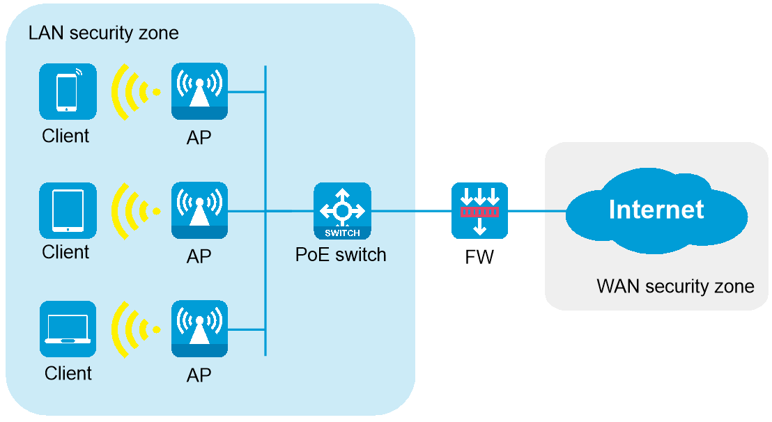
Suitable for small and medium-sized office areas (such as conference rooms and office areas), which are approximately 300 to 500 square meters, with approximately 60 to 100 online endpoints. PoE switches provide PoE power to multiple APs, and the firewall acts as the egress gateway to provide security protection.
Network topology
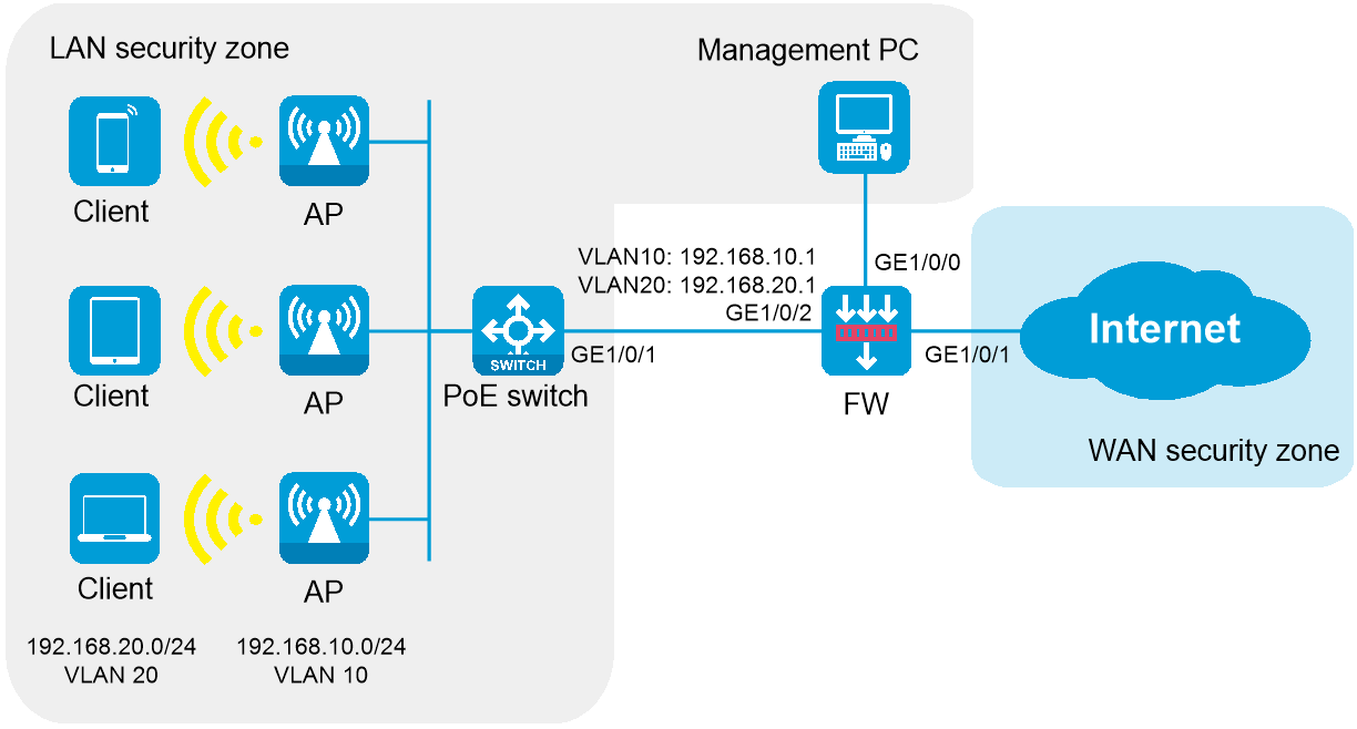
As shown in Figure 1, the AP operates in fit mode and is connected to the egress gateway firewall through a PoE switch. The firewall also acts as a DHCP server to assign IP addresses to the AP and wireless clients, and provides security protection for internal devices.
Device model selection
Table 1 Device model selection recommended
|
Role |
Recommended model |
|
Egress gateway firewalls |
F100-C-A1 and F100-C-A2 |
|
PoE switches |
Switches that support PoE power supply (such as S5120V3-10P-PWR-LI). |
|
APs |
WA6120, WA6120H, WA6120X, and WA6126 |
Firewall basics
Firewall appearance introduction
The product appearance of F100-C-A1 and F100-C-A2 is briefly introduced below. For other specific parameters, see H3C SecPath F100-C-A Firewall Series Installation Guide.
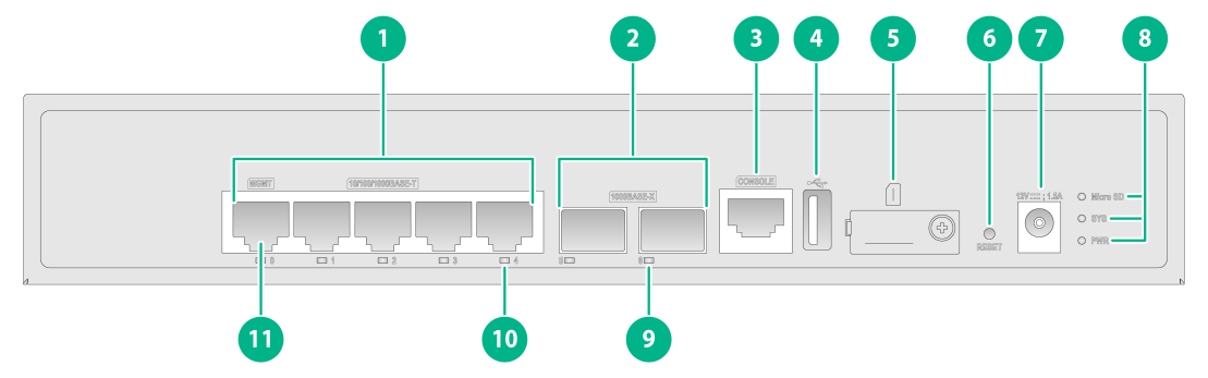
F100-C-A1
The device front panel has two 1000BASE-X Ethernet fiber ports, five 10/100/1000BASE-T adaptive Ethernet copper ports (including one management Ethernet port), one USB port, one console port, one reset button, and one Micro SD card slot. The specific structure is shown in the figure below.
Figure 2 Front panel
|
1: 10/100/1000BASE-T Ethernet copper ports |
2: 1000BASE-X Ethernet fiber ports |
|
3: Console port |
4: USB port (host mode, Type A) |
|
5: Micro SD card slot |
6: Reset button (for device reboot) |
|
7: DC-input power receptacle |
8: Micro SD card, system status (SYS), and power status (PWR) LEDs |
|
9: 1000BASE-X Ethernet fiber port LED |
10: 10/100/1000BASE-T Ethernet copper port LED |
|
11: Management Ethernet port (MGMT) |
|
|
|
NOTE: The reset button restarts the firewall. It does not restore the factory defaults. |
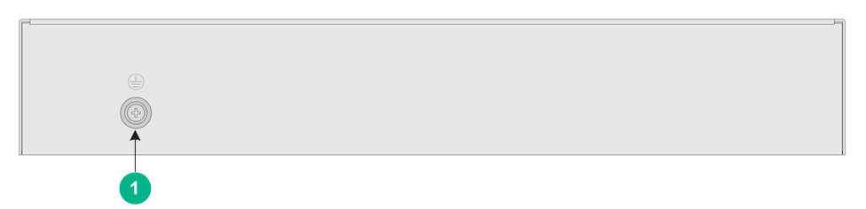
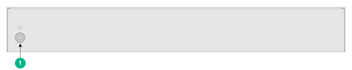
Figure 3 Rear panel
|
1: Grounding screw |
F100-C-A2
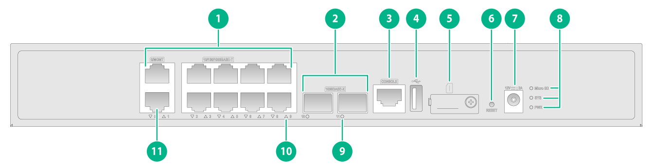
The device front panel has two 1000BASE-X Ethernet fiber ports, ten 10/100/1000BASE-T adaptive Ethernet copper ports (including one management Ethernet port), one USB port, one console port, one reset button, and one Micro SD card slot. The specific structure is shown in the figure below.
Figure 4 Front panel
|
1: 10/100/1000BASE-T Ethernet copper ports |
2: 1000BASE-X Ethernet fiber ports |
|
3: Console port |
4: USB port (host mode, Type A) |
|
5: Micro SD card slot |
6: Reset button (for device reboot) |
|
7: DC-input power receptacle |
8: Micro SD card, system status (SYS), and power status (PWR) LEDs |
|
9: 1000BASE-X Ethernet fiber port LED |
10: 10/100/1000BASE-T Ethernet copper port LED |
|
11: Management Ethernet port (0/MGMT) |
|
|
|
NOTE: The reset button restarts the firewall. It does not restore the factory defaults. |
Figure 5 Rear panel
|
1: Grounding screw |
Factory defaults of the firewalls
The following table shows the factory defaults of the firewall devices. You can also obtain default username and password information from the nameplate on the device.
Table 2 Factory defaults of the firewalls
|
Login information item |
Default settings |
Remarks |
|
Username |
admin |
N/A |
|
Password |
admin |
N/A |
|
Login type |
· Log in to the device through the Web interface. · Log in to the device through the Console port. |
Other login types need to be configured by yourself. |
|
IP address |
· VLAN-interface 1 · IP address: 192.168.0.1/24 (The firewall device acts as the DHCP server to assign the IP address to the interface. It is assigned 2 or 3 minutes after the device starts.) |
If another device on the network is the DHCP server, the IP address is depends on the DHCP server configuration. View the IP address assigned to the firewall device on the DHCP server. |
|
Ethernet copper ports |
· GE1/0/1: Operates in Layer 3 mode. · GE1/0/0, and GE1/0/2 through GE1/0/9: Operate in Layer 2 mode and join VLAN 1. |
|
|
Security zones |
· Local: Device itself · Management: Zone for managing the device · Trust: Trusted network zone · Untrust: Untrusted network zone · DMZ: Isolated network zone · LAN: Local area network. Ethernet interfaces other than GE1/0/1 and VLAN-interface 1 belong to the LAN security zone. |
N/A |
|
Security policy |
· AUTONET_LOCAL2ANY_DONTMODIFY: Permits packets from Local to any security zone by default. · AUTONET_LAN2LOCAL_DONTMODIFY: Permits packets from LAN to Local by default. · AUTONET_LAN2LAN_DONTMODIFY: Permits packets from LAN to LAN by default. |
N/A |
Example: Configuring unified firewall and AC (Web interface)
Network configuration
A company wants to provide better wireless network services to its employees and has high security requirements. It hopes to achieve full wireless network coverage within the company and uses a firewall as the egress gateway to ensure the security of the internal network.
As shown in Figure 6, the APs are deployed in the internal network of the company in fit mode and are connected to the gateway firewall through a PoE switch to access the Internet. The firewall also acts as a DHCP server to assign IP addresses to the APs and wireless clients, and provides security protection for internal devices.
Analysis
This example uses the following approach for network configuration:
1. Configure the egress gateway firewall.
a. Log in to the local Web management interface of the firewall.
b. Configure the firewall to connect to the ISP network and access the Internet.
c. Configure the internal network interfaces, create management and service VLAN interfaces, and assign IP addresses to the VLAN interfaces.
d. Configure DHCP address pools for the management VLAN and service VLANs.
e. Configure a security policy.
f. Configure NAT to ensure that internal users can access the Internet.
g. Configure the AC function for the firewall to act as an AC to manage APs.
2. Configure the PoE access switch:
a. Configure the management IP address for the PoE access switch.
b. Log in to the local Web management interface of the PoE access switch.
c. Create service VLANs and permit all service VLANs.
d. Enable PoE to supply power to APs.
Deployment planning
Restrictions and guidelines
This configuration example was created and verified in a lab environment, and all the devices were started with the factory default configuration. When you are working on a live network, make sure you understand the potential impact of every command on your network.
Device model selection
Table 3 Device model selection
|
Role |
Model |
Software version |
|
Egress gateway firewall |
F100-C-A2 |
F8590P09 |
|
PoE switches |
S5120V3-28P-PWR-LI |
R6343P05 |
|
AP |
WA6120X |
R2593P03 |
Network configuration plan
Table 4 Network configuration plan
|
Item |
Detailed planning data |
|
Wireless endpoint network |
· Network segment: 192.168.20.0/24. The firewall acts as a DHCP server to assign IP addresses to endpoints. · Gateway location: Firewall · Gateway interface IP address: 192.168.20.1/24 · Service VLAN: VLAN 20 · Encryption method: PSK |
|
Network segment for firewall, switch, and AP interconnection |
· Network segment: 192.168.10.0/24 · Firewall interconnect IP address: 192.168.10.1/24 · AP IP addresses: Obtained automatically from the firewall. · Management VLAN: VLAN 10 |
|
Firewall interfaces |
· Interface GE1/0/0: The management interface of firewall F100-C-A2, which uses the default factory configuration. Administrators can manage the firewall through this interface. With the factory configuration, interface GE1/0/0 operates in Layer 2 mode, joins the LAN security zone, and has a security policy that permits source security zone LAN to access destination security zone Local. The factory configuration for other firewalls varies with the firewall models. · Interface GE1/0/1 operates in Layer 3 mode and joins the WAN security zone. It can be connected to the external network in the following methods: DHCP, PPPoE, and specified IP address. Select a method according to the actual network of the service provider. · Interface GE1/0/2 is connected to the switch. It operates in Layer 2 mode and joins the LAN security zone. Create interfaces for management VLAN 10 and service VLAN 20, respectively, with the interface mode set to trunk, allowing only VLAN 10 and VLAN 20 to pass through. |
|
Switch interfaces |
· Interface GE1/0/1 is connected to the firewall and configured as trunk port, allowing VLAN 10 and VLAN 20 to pass through. · Multiple GE interfaces are connected to APs, with PVID set to 10 and interface type set to trunk, allowing VLAN 10 and VLAN 20 to pass through. |
|
APs |
Operating mode: Fit mode |
Procedures
Configuring the egress gateway firewall
Connecting a PC to the firewall
1. Connect the PC to the GE1/0/0 interface on the firewall by using an Ethernet cable.
2. Click on the ![]() icon in the lower
right corner of the computer, and then click Open Network
and Sharing Center.
icon in the lower
right corner of the computer, and then click Open Network
and Sharing Center.
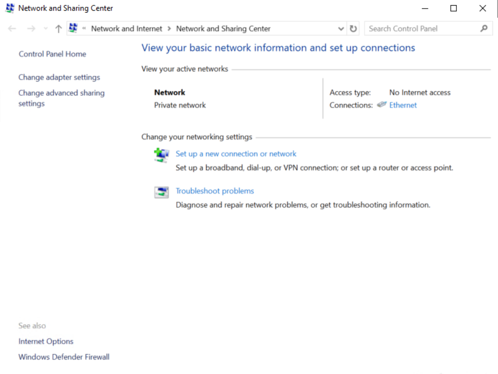
3. In the Network and Sharing Center dialog box that opens, click Local Area Connection.
Figure 7 Network and Sharing Center window

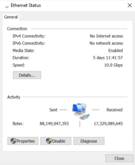
4. In the Local Area Connection Status dialog box, click Properties to open the Local Area Connection Properties dialog box.
Figure 8 Local Area Connection Status
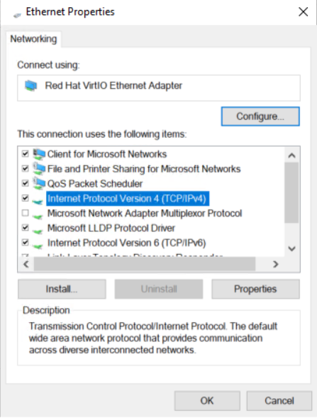
5. In the Local Area Connection Properties dialog box that opens, click Internet Protocol Version 4 (TCP/IPv4), and then click OK.
Figure 9 Local Area Connection Properties

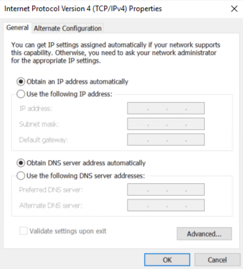
6. In the Internet Protocol Version 4 (TCP/IPv4) dialog box that opens, configure the IP address for the PC to ensure communication with the firewall in either of the following two methods:
¡ Select Obtain an IP address automatically and Obtain DNS server address automatically to configure the PC to get IP settings automatically using DHCP.
Figure 10 Configuring the PC to automatically obtain an IP address
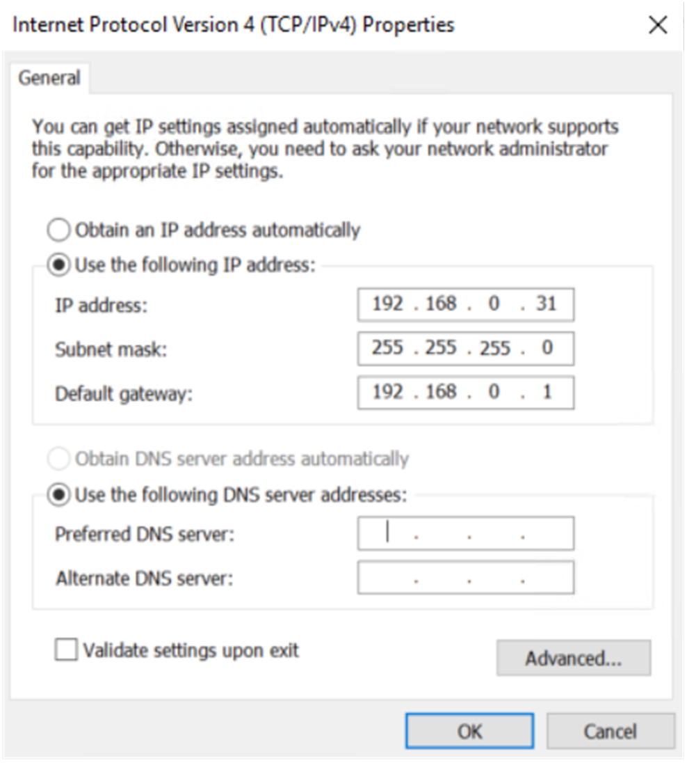
¡ Manually change the IP address of the PC to any address within the 192.168.0.0/24 network segment (except 192.168.0.1), for example, 192.168.0.31. (Note: After modifying the default login address of the firewall later, use the IP address within the modified network segment to log in to the firewall again.)
Figure 11 Manually configuring the IP address of the PC
Logging in to the firewall
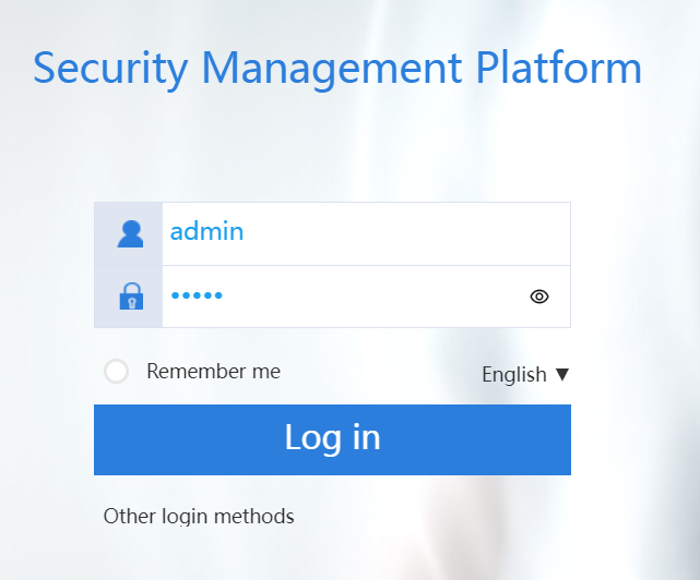
1. Enter https://192.168.0.1 in the browser address bar on the PC and then press Enter to log in to the Web interface of the firewall.
2. Enter the default username admin and password admin, and then click Login. Change the login password as prompted.
Figure 12 Logging in to the firewall
Configuring the external network interface
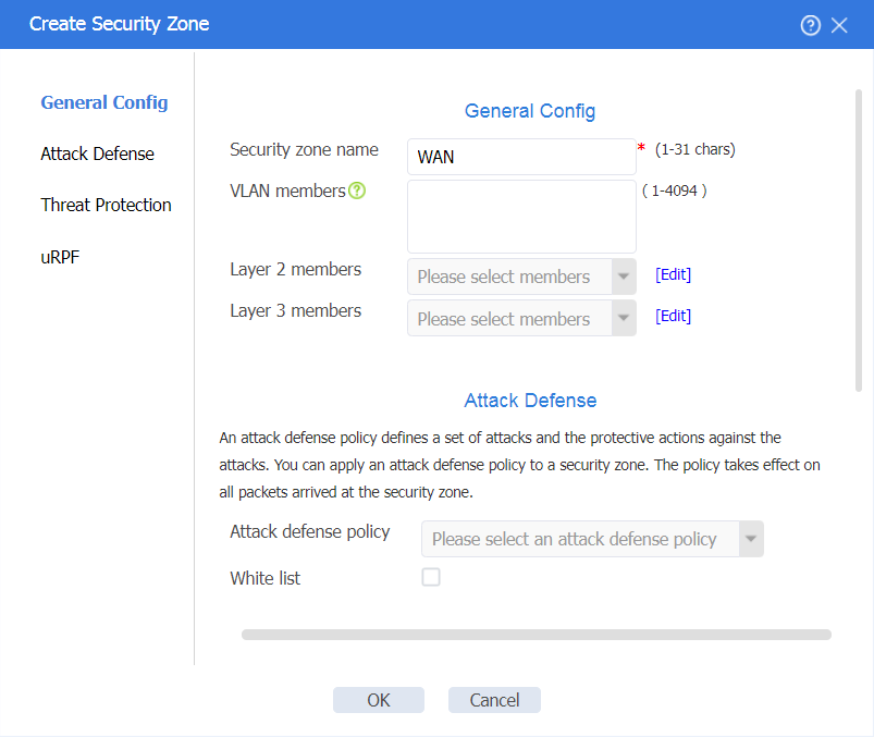
1. On the top navigation bar, click Network. In the left navigation pane, select Security Zones. Click Create to create a security zone named WAN.
Figure 13 Creating the WAN security zone
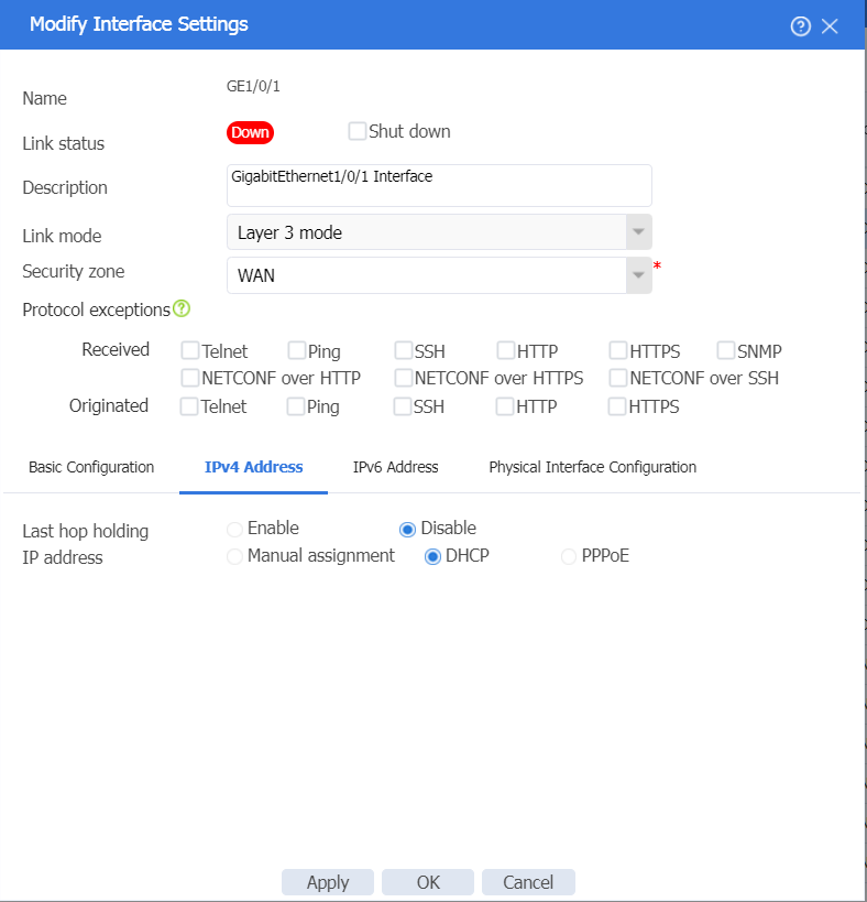
2. In the left navigation pane, select Interface Configuration > Interfaces. Click the Edit icon on the right side of interface GE1/0/1, and configure the interface as follows:
¡ Configure the interface to operate at Layer 3.
¡ Add the interface to security zone WAN.
¡ Select the IPv4 address configuration method according to the service provider. DHCP is selected in this example.
- If you select PPPoE, enter the PPPoE account and password provided by the service provider.
- If you select DHCP, the DHCP server automatically assigns the public IP addresses for accessing the WAN.
- If you select manual assignment, enter the IP address, subnet mask, and gateway address of the WAN.
¡ Click OK.
Figure 14 Editing interface GE1/0/1
Configuring the internal network interfaces
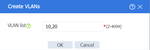
1. On the top navigation bar, click Network. In the left navigation pane, select Link > VLANs. Click Create to create VLAN 10 (management VLAN) and VLAN 20 (service VLAN) as follows:
Figure 15 Creating VLANs
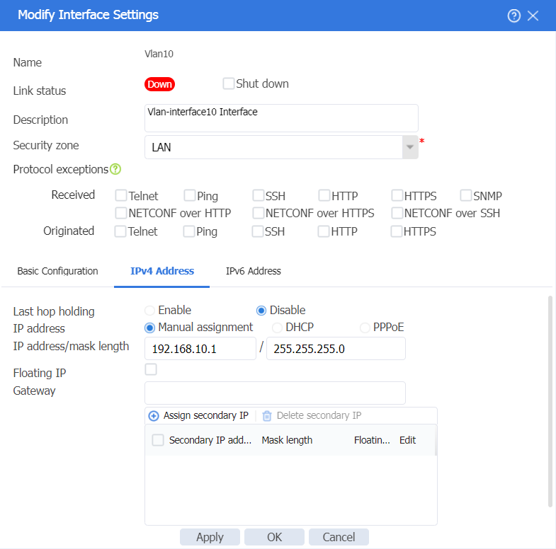
2. In the left navigation pane, select Interface Configuration > Interfaces. Click Create interface, and then create a VLAN interface for VLAN 10, the management VLAN. The configuration is as follows:
¡ Add the interface to security zone LAN.
¡ Configure the IPv4 address/subnet mask as 192.168.10.1/255.255.255.0.
¡ Click OK.
Figure 16 Creating a VLAN interface for VLAN 10
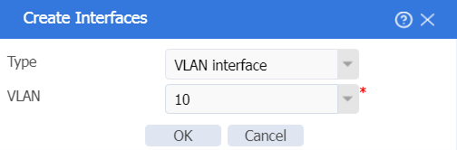
Figure 17 Editing Vlan10 interface settings
3. In the left navigation pane, select Interface Configuration > Interfaces. Click Create interface, and then create a VLAN interface for VLAN 20, the service VLAN. The configuration is as follows:
¡ Add the interface to security zone LAN.
¡ Configure the IPv4 address/subnet mask as 192.168.20.1/255.255.255.0.
¡ Click OK.
Figure 18 Creating Vlan20 interface
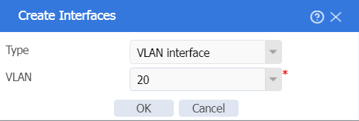
Figure 19 Editing Vlan20 interface settings

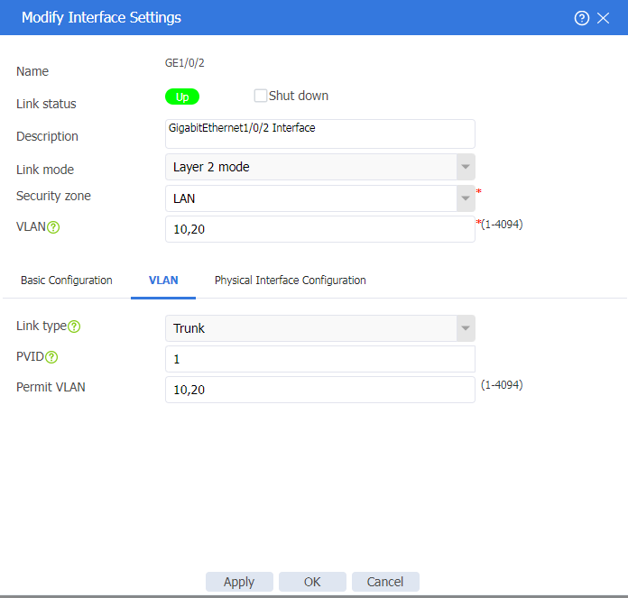
4. Click the Edit icon for GE1/0/2. Configure the interface as follows:
¡ Add the interface to security zone LAN.
¡ Select Trunk as the link type.
¡ Configure the permit VLANs as VLAN 10 and VLAN 20.
¡ Click OK.
Figure 20 Editing interface GE1/0/2
Configuring the DHCP address pool
1. On the top navigation bar, click Network. In the left navigation pane, select DHCP > DHCP Address Pools. Click Create address pool to create a DHCP server address pool named poolforap as follows:
¡ Configure the subnet for dynamic allocation as 192.168.10.0/24 and the excluded address range as 192.168.10.1.
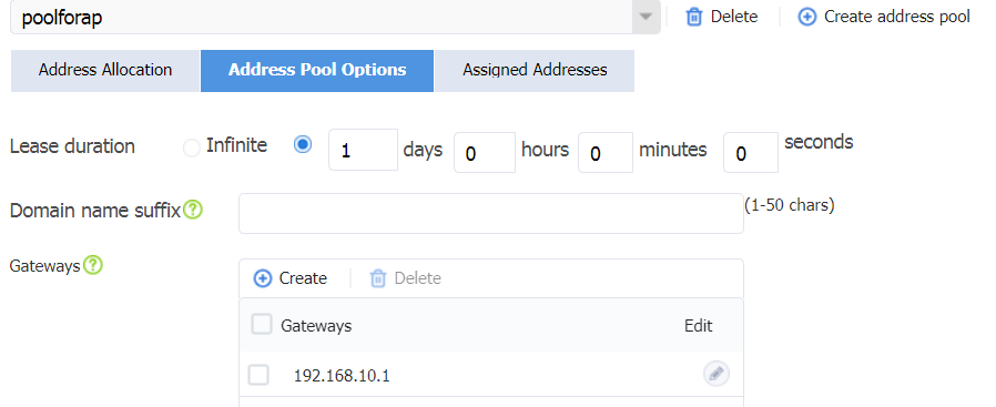
¡ Click the Address Pool Options tab, and then click Create to create a gateway. Configure the gateway address as 192.168.10.1 and then click OK.
¡ Click OK.
Figure 21 Creating a DHCP server address pool named poolforap
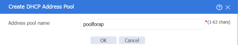
Figure 22 Configuring the address pool subnet
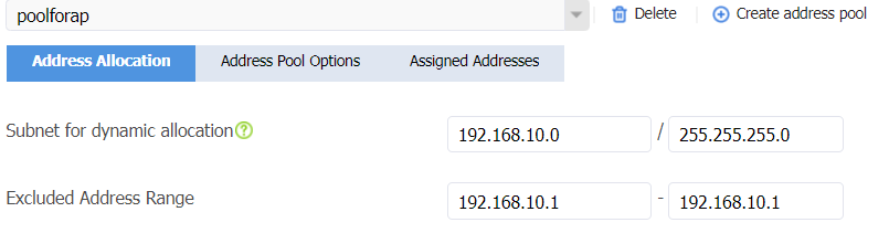
Figure 23 Configuring the gateway
2. Click Create address pool to create a DHCP server address pool named poolforsta as follows:
¡ Configure the subnet for dynamic allocation as 192.168.20.0/24 and the excluded address range as 192.168.20.1.
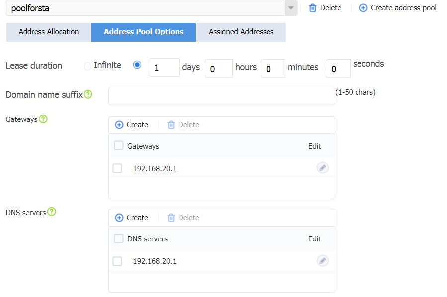
¡ Click the Address Pool Options tab, and then click Create in the Gateways area to create a gateway. Configure the gateway address as 192.168.20.1. Click Create in the DNS servers area to create a DNS server. Configure the DNS server address as 114.114.114.114 (specify the DNS server address for wireless clients according to your actual network configuration). Click OK.
¡ Click OK.
Figure 24 Create a DHCP server address pool named poolforsta
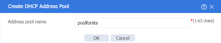
Figure 25 Configuring the address pool subnet
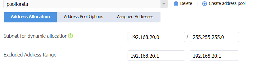
Figure 26 Configuring the gateway
Configuring a security policy
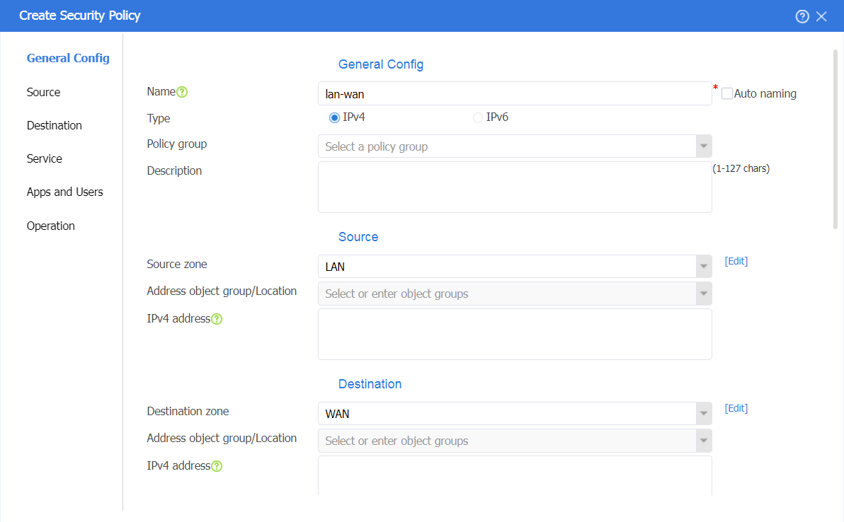
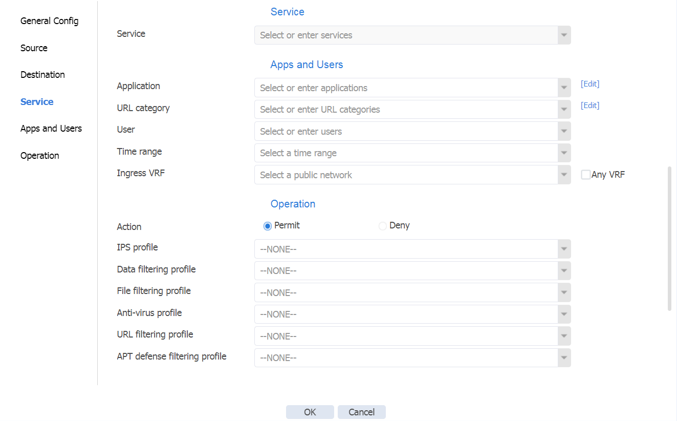
# On the top navigation bar, click Policies. In the left navigation pane, select Security Policies. Select Create > Create a policy to create a security policy named lan-wan with the following configuration:
· Security policy name: lan-wan
· Source security zone: LAN, destination security zone: WAN
· Action: Permit
· Use the default configuration for other parameters and then click OK.
Figure 27 Creating a security policy named lan-wan
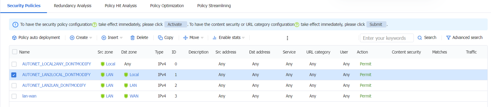
# F100-C-A2 has a default security policy AUTONET_LAN2LOCAL_DONTMODIFY with the following default configuration:
· Source security zone: LAN
· Destination security zone: Local
· Action: Permit
# F100-C-A2 has a default security policy AUTONET_LOCAL2ANY_DONTMODIFY, which allows packets from security zone Local to any destination security zone to pass by default. The factory configuration is as follows:
· Source security zone: Local
· Destination security zone: Any
· Action: Permit
Figure 28 Device factory default security policies
Configuring NAT
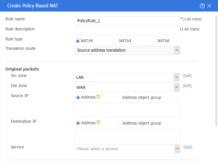
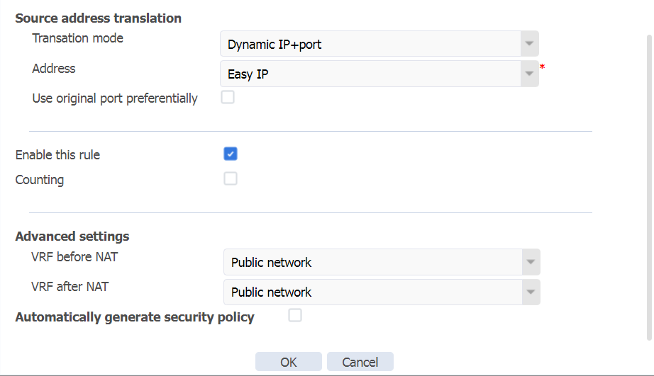
# On the top navigation bar, click Policies. In the left navigation pane, select Policy-based NAT. Click Create to create a NAT policy with the following configuration:
· The rule name is PolicyRule_1.
· The rule type is NAT44.
· The translation mode is source address translation.
· The source security zone is LAN.
· The destination security zone is WAN.
· The translation mode is dynamic IP + port.
· Address type is Easy IP.
· Select Enable this rule.
· Click OK.
Figure 29 Creating a NAT policy
Configuring the wireless AC functions
|
|
CAUTION: If the factory default operating mode of an AP is Cloud mode, you need to switch the operating mode of the AP to fit mode. |
1. On the top navigation bar, click Network. In the left navigation pane, select WLAN AC.
2. Configure an AP by using at least one of the two methods, manual AP creation and automatic AP configuration.
¡ Create a manual AP:
# In the left navigation pane, select Quick Start > Add New AP > Add New AP. Configure an AP as follows:
- Name—ap1.
- Model—WA6120X.
- Serial ID—219801A3WYP22A00000V. You can also add the AP by specifying the AP's MAC address.
- Use the default values for other parameters and then click OK.
Figure 30 Creating a manual AP
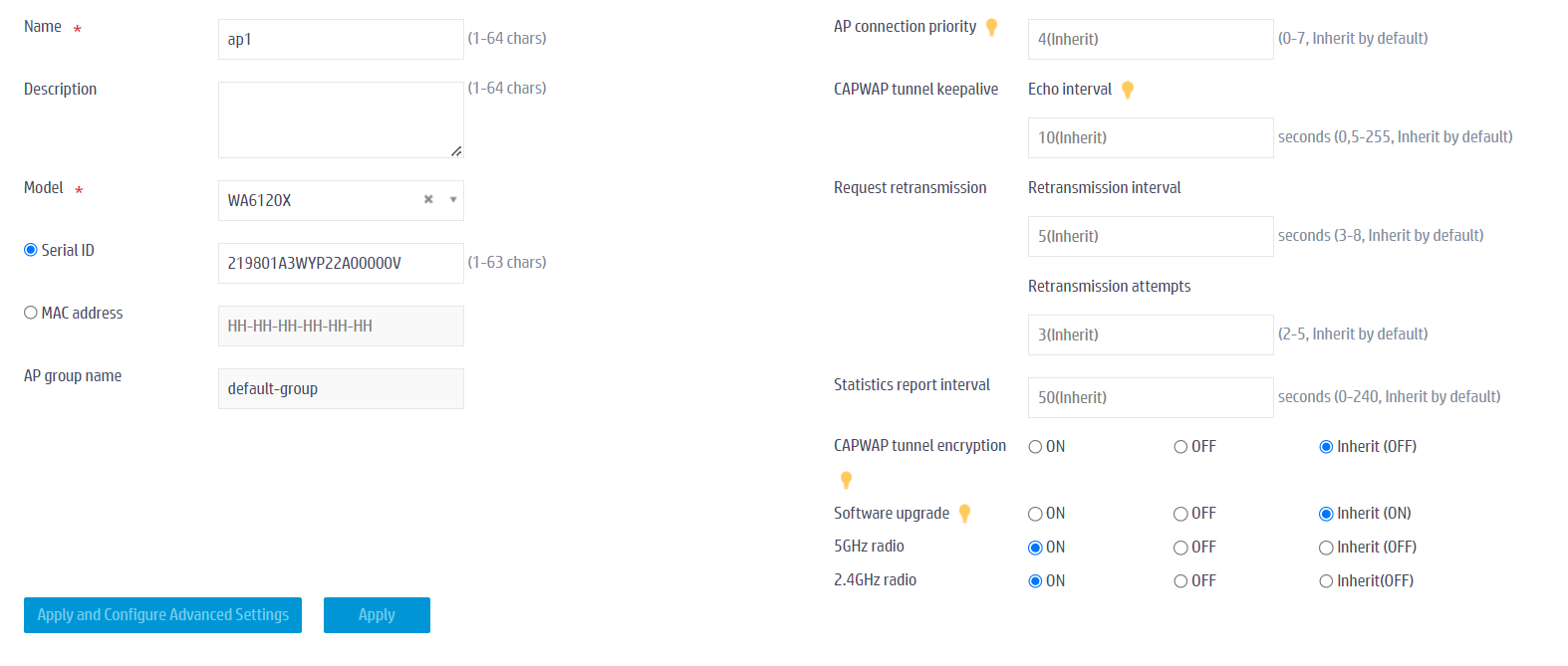
# In the left navigation pane, select Wireless Configuration > AP Management > AP Global Settings. Turn off the software upgrade function for APs.
Figure 31 Disabling software upgrade for APs
|
|
NOTE: For more information about AP software upgrade, see “Automatic upgrade for APs.” |
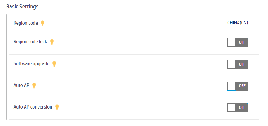
¡ Configure auto AP. The name of an auto AP is the MAC address of the AP.
# In the left navigation pane, select Wireless Configuration > AP Management > AP Global Settings.
- Turn off the software upgrade function for APs.
- Turn on auto AP.
- Turn on auto AP conversion.
Figure 32 Configuring auto AP

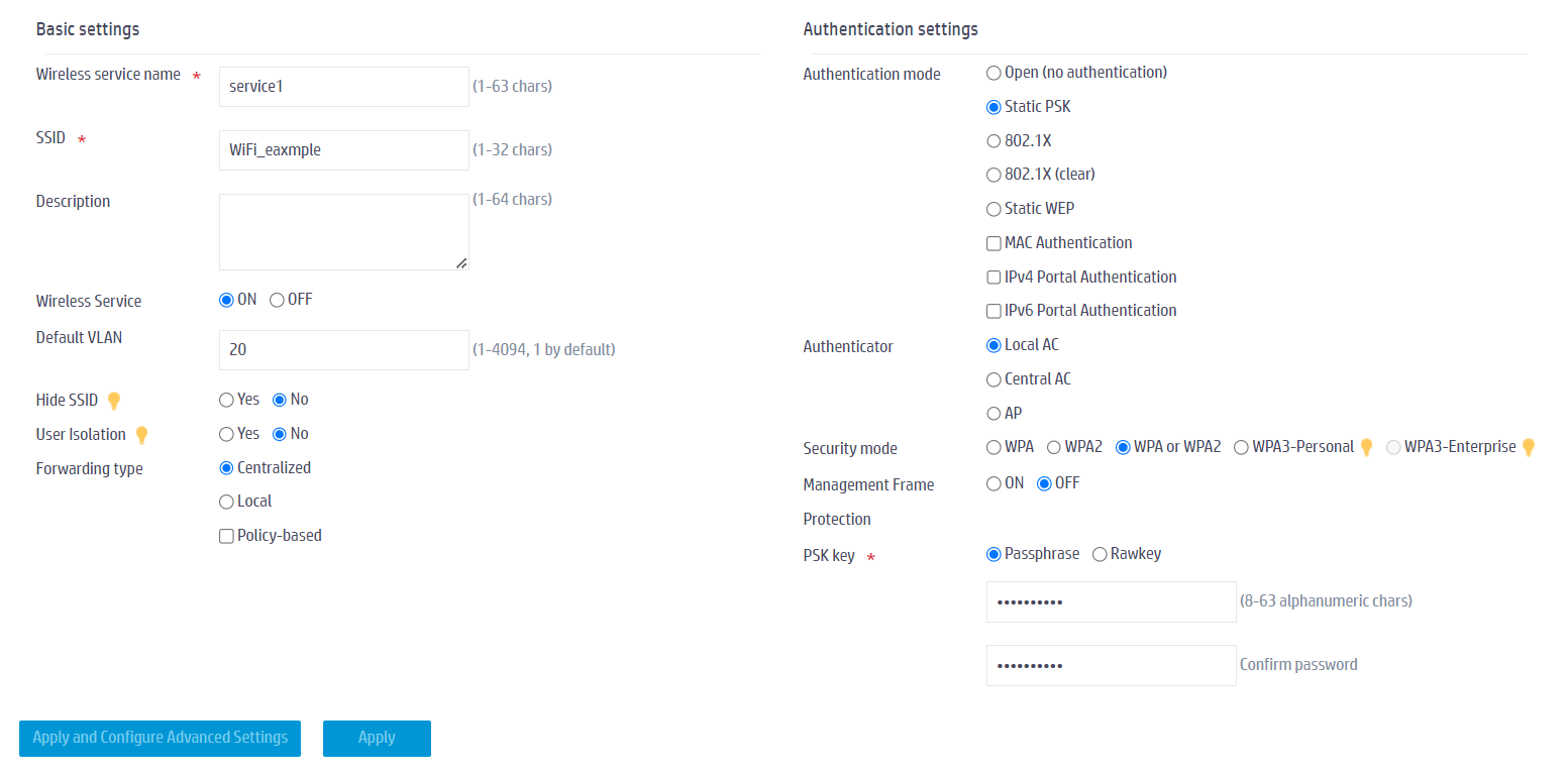
3. In the left navigation pane, select Quick Start > Add New SSID > Add New SSID. Configure a wireless service (Wi-Fi) as follows:
- Configure the wireless service name as service1.
- Configure the SSID as WiFi_example.
- Enable the wireless service template.
- Set the default VLAN to service VLAN 20.
- Select static PSK authentication as the authentication mode, and select WPA or WPA2 as the security mode, and enter the PSK key.
- Use the default values for other parameters and click Apply and Configure Advanced Settings to save the configuration.
Figure 33 Adding a wireless network
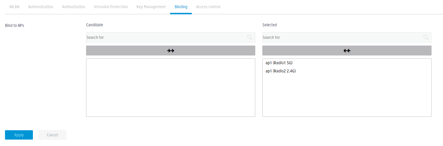
4. Click the Binding tab and bind the wireless service template to the 5GHz and 2.4GHz radio frequencies.
Figure 34 Binding service template service1 to RFs
Configuring the PoE access switch
Connecting a PC to the PoE switch
1. Use a console cable to connect the serial port of the management PC with the console port of the PoE switch. Configure the IP address of interface VLAN1, which is 192.168.1.2 in this example.
|
|
NOTE: DHCP is enabled on F100-C-A2 by default. In this example, the PoE switch can be assigned an IP address in the 192.168.0.0/24 subnet. You can use the display interface brief command to view the IP address assigned to interface Vlan1. If there is no DHCP server in your network, you need to manually configure the IP address for the PoE switch. |
2. Change the IP address of the PC interface to be in the same subnet as the switch. Change the IP address of the PC to any address within the 192.168.1.0/24 subnet.
Note: Do not use an IP address that is already configured on another device.
Logging in to the PoE access switch
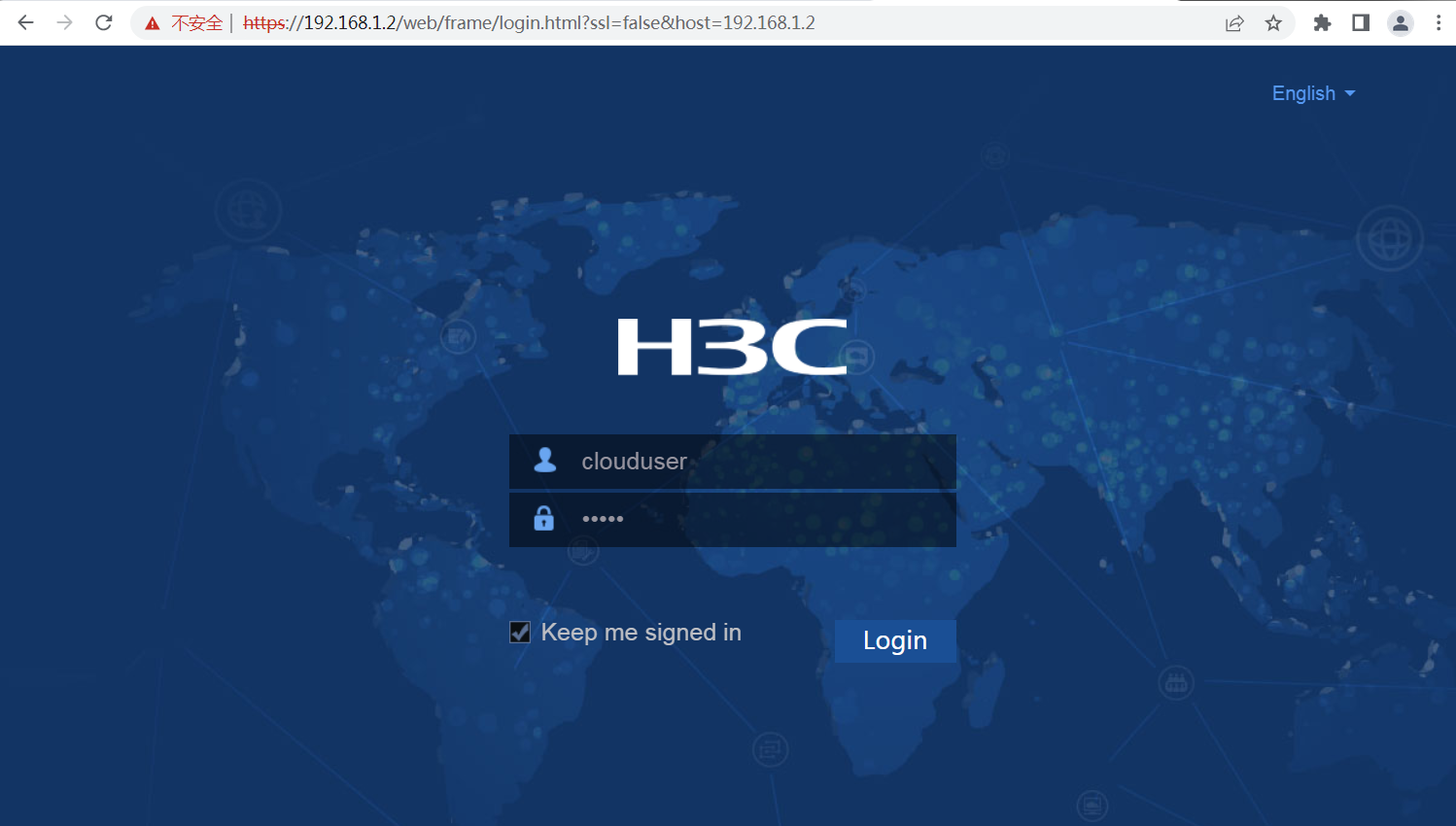
1. Use an Ethernet cable to connect the PC and interface GE1/0/3 on the PoE switch. On the PC, type https://192.168.1.2 in the browser address bar and press Enter to access the Web login interface of the PoE access switch.
2. Enter the default username clouduser and password admin, and then click Login. Change the login password as prompted.
Figure 35 Logging in to the PoE access switch
Creating VLANs
Create service VLAN 20 according to the plan.
1. Navigate to the Network > Links > VLAN page.
2. Click the Create VLAN icon. The Create VLAN list dialog box opens.
¡ Create VLAN 10 (management VLAN) and VLAN 20 (service VLAN)
¡ Click OK.
Figure 36 Creating the management VLAN 10 and service VLAN 20

Setting interface types and assigning them to VLANs
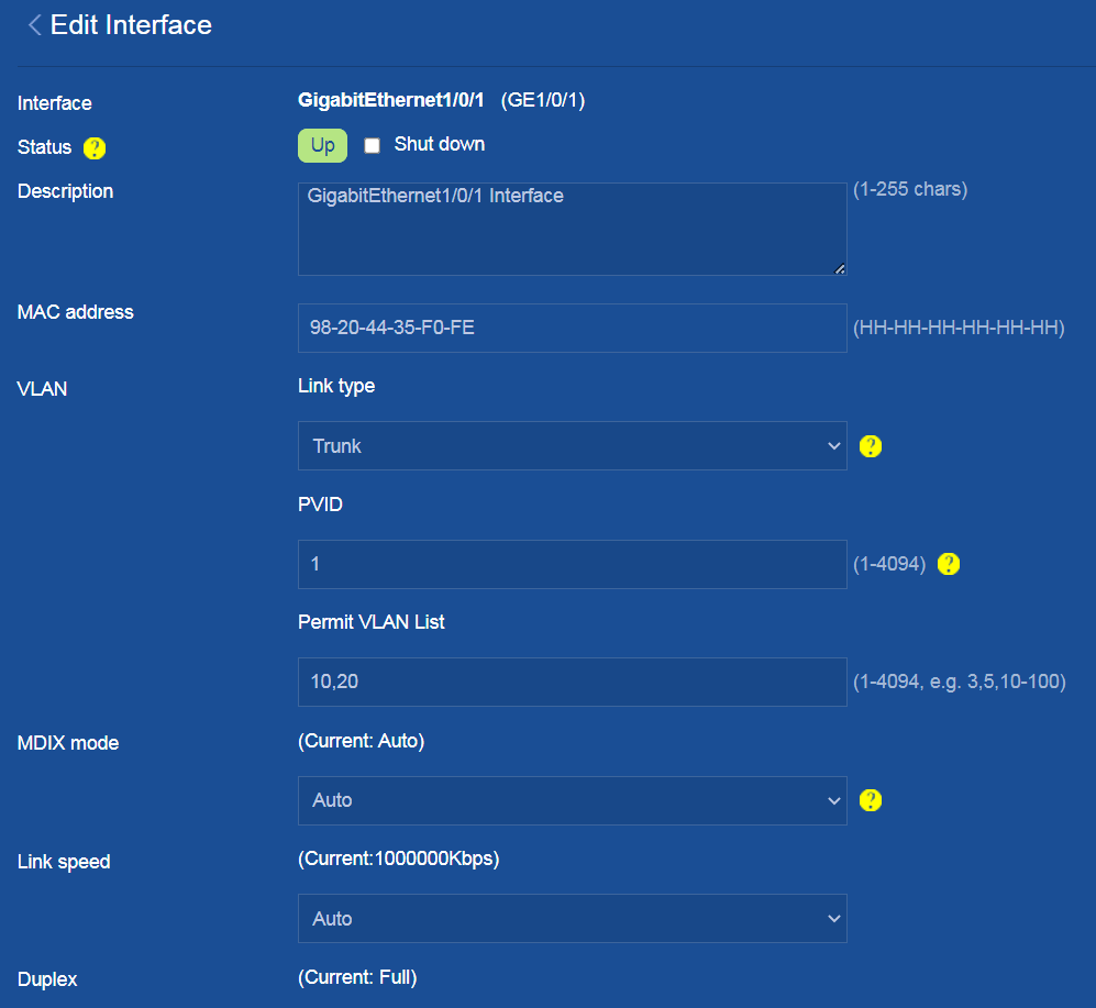
Configure interface GE1/0/1 connected to the firewall and the GE interfaces connected to APs as follows:
1. Navigate to the Network > Interfaces > Interfaces page.
2. Click the Details icon for interface GE1/0/1 to enter the page for editing interface settings.
¡ Configure the link type as Trunk, and enter 10,20 in the Permit VLAN List field.
¡ Use the default values for other parameters.
¡ Click OK.
Figure 37 Configuring interface GE1/0/1
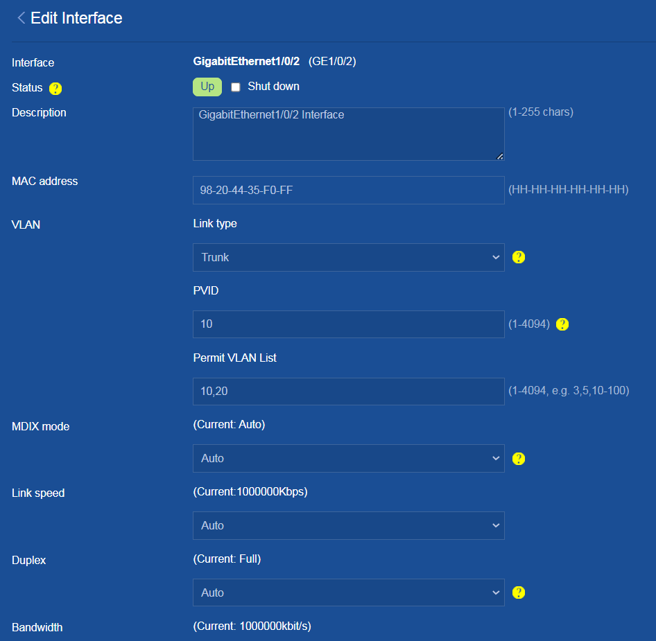
3. Click the Details icon for interface GE1/0/2 (interface connected to an AP) to edit the interface settings as follows:
¡ Configure the link type as Trunk, set the PVID to 1, and enter 10,20 in the Permit VLAN List field.
¡ Use the default values for other parameters.
¡ Click OK.
Figure 38 Configuring interface GE1/0/2
Enabling PoE
PoE is enabled on the switch by default. If PoE is already enabled on the switch’s interfaces connected to APs, you can skip this step.
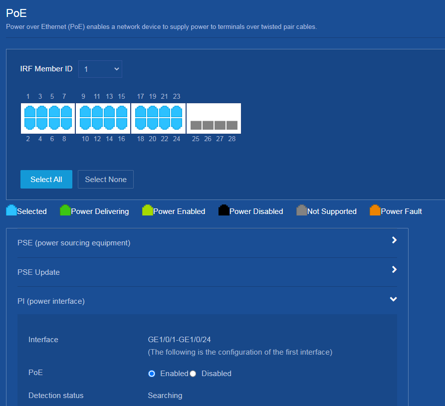
# Enable PoE on the GE interfaces connected to APs to supply power to the APs:
1. Navigate to the PoE > PoE page.
2. Click Select All to select all interfaces.
3. Click PI to enable PoE for all selected interfaces.
Figure 39 Enabling PoE power supply
Verifying the configuration
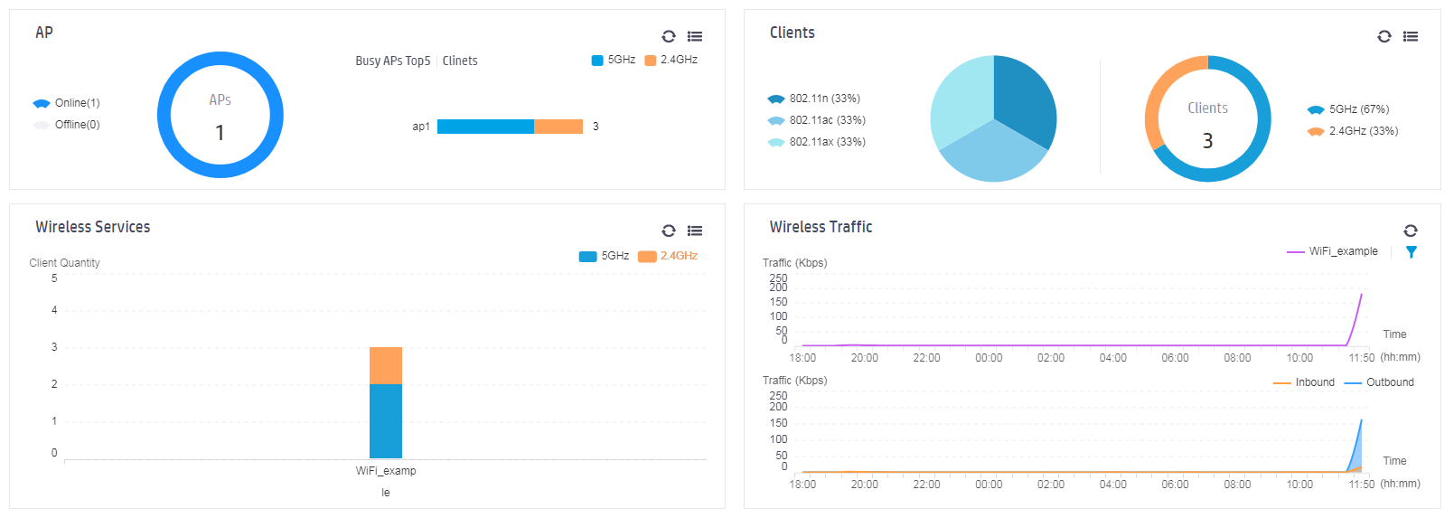
1. After the wireless terminal is connected to the wireless network, open the WLAN AC page, and then select Dashboard > Dashboard in the left navigation pane to enter the dashboard page, where you can view statistics for all APs, clients, wireless services, and wireless traffic.
Figure 40 View dashboard
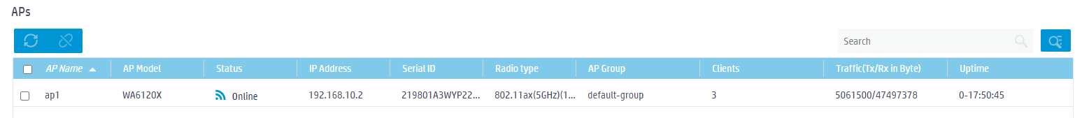
2. Click the ![]() icon in the upper
right corner of the AP widget to view statistics for all APs, including AP
model, status, AP serial number, client count, and other information.
icon in the upper
right corner of the AP widget to view statistics for all APs, including AP
model, status, AP serial number, client count, and other information.
Figure 41 AP list
3. Click the Clients tab to view information about online clients, including the client's MAC address, IP address, and speed.
Figure 42 Client list

Example: Configuring unified firewall and AC (CLI)
Network configuration
A company wants to provide better wireless network services to its employees and has high security requirements. It hopes to achieve full wireless network coverage within the company and uses a firewall as the egress gateway to ensure the security of the internal network.
As shown in Figure 43, the APs are deployed in the internal network of the company in fit mode and are connected to the gateway firewall through a PoE switch to access the Internet. The firewall also acts as a DHCP server to assign IP addresses to the AP and wireless clients, and provides security protection for internal devices.

Analysis
This example uses the following approach for network configuration:
1. Configure the egress gateway firewall.
a. Login to the firewall through the console port.
b. Configure the firewall to connect to the ISP network and access the Internet.
c. Configure the internal network interfaces, create management and service VLAN interfaces, and assign IP addresses to the VLAN interfaces.
d. Configure DHCP address pools for the management VLAN and service VLANs.
e. Configure a security policy.
f. Configure NAT to ensure that internal users can access the Internet.
g. Configure the AC function for the firewall to act as an AC to manage APs.
2. Configure the PoE access switch:
a. Log in to the PoE access switch through the console port.
b. Create service VLANs and permit all service VLANs.
c. Enable PoE to supply power to APs.
Deployment planning
Restrictions and guidelines
This configuration example was created and verified in a lab environment, and all the devices were started with the factory default configuration. When you are working on a live network, make sure you understand the potential impact of every command on your network.
Device model selection
Table 5 Device model selection
|
Role |
Model |
Software version |
|
Egress gateway firewall |
F100-C-A2 |
F8590P09 |
|
PoE switches |
S5120V3-28P-PWR-LI |
R6343P05 |
|
AP |
WA6120X |
R2593P03 |
Network configuration plan
Table 6 Network configuration plan
|
Item |
Detailed planning data |
|
Wireless endpoint network |
· Network segment: 192.168.20.0/24. The firewall acts as a DHCP server to assign IP addresses to endpoints. · Gateway location: Firewall · Gateway interface IP address: 192.168.20.1/24 · Service VLAN: VLAN 20 · Encryption method: PSK |
|
Network segment for firewall, switch, and AP interconnection |
· Network segment: 192.168.10.0/24 · Firewall interconnect IP address: 192.168.10.1/24 · AP IP addresses: Obtained automatically from the firewall. · Management VLAN: VLAN 10 |
|
Firewall interfaces |
· GE1/0/0 interface: The management interface of firewall F100-C-A2, which uses the default factory configuration. Administrators can manage the firewall through this interface. With the factory configuration, interface GE1/0/0 operates in Layer 2 mode, joins the LAN security zone, and has a security policy that permits source security zone LAN to access destination security zone Local. The factory configuration for other firewalls varies with the firewall models. · Interface GE1/0/1 operates in Layer 3 mode and joins the WAN security zone. It can be connected to the external network in the following methods: DHCP, PPPoE, and specified IP address. Select a method according to the actual network of the service provider. · Interface GE1/0/2 is connected to the switch. It operates in Layer 2 mode and joins the LAN security zone. Create interfaces for management VLAN 10 and service VLAN 20, respectively, with the interface mode set to trunk, allowing only VLAN 10 and VLAN 20 to pass through. |
|
Switch interfaces |
· Interface GE1/0/1 is connected to the firewall and set as a trunk port, allowing VLAN 10 and VLAN 20 to pass through. · Multiple GE interfaces are connected to APs, with PVID set to 10 and interface type set to trunk, allowing VLAN 10 and VLAN 20 to pass through. |
|
AP |
Operating mode: Fit mode |
Procedure
Configuring the egress gateway firewall
Connecting the firewall and PC
1. Connect the PC to the GE1/0/0 interface on the firewall by using an Ethernet cable.
2. Click on the ![]() icon in the lower
right corner of the computer, and then click Open Network
and Sharing Center.
icon in the lower
right corner of the computer, and then click Open Network
and Sharing Center.
3. In the Network and Sharing Center dialog box that opens, click Local Area Connection.
Figure 44 Network and Sharing Center window
4. In the Local Area Connection Status dialog box that opens, click Properties.
Figure 45 Local Area Connection Status

5. In the Local Area Connection Properties dialog box that opens, click Internet Protocol Version 4 (TCP/IPv4).
Figure 46 Local Area Connection Properties
6. In the Internet Protocol Version 4 (TCP/IPv4) dialog box that opens, configure the IP address for the PC to ensure communication with the firewall in either of the following two methods:
¡ Select Obtain an IP address automatically and Obtain DNS server address automatically to configure the PC to get IP settings automatically using DHCP.
Figure 47 Configuring the PC to automatically obtain an IP address

¡ Manually change the IP address of the PC to any address within the 192.168.0.0/24 network segment (except 192.168.0.1), for example, 192.168.0.31. (Note: After modifying the default login address of the firewall later, use the IP address within the modified network segment to log in to the firewall again.)
Figure 48 Manually configuring the IP address of the PC

Login to the firewall through the console port
1. Connect the PC and firewall by using a console cable. First insert the DB-9 (female)/standard USB plug of the console cable into the 9-pin (male) serial port/USB port of the PC, and then insert the RJ-45 plug end into the console port of the firewall.
2. When building a local configuration environment through the console port, it is necessary to establish a connection with the firewall through a terminal emulation program such as HyperTerminal or PuTTY. You can run these programs to connect network devices, Telnet or SSH sites. For detailed descriptions and usage instructions of these programs, see the user guides for the programs. After opening the terminal emulation program, set the terminal parameters as follows.
¡ Bits per second—9600
¡ Data bits—8
¡ Stop bits—1
¡ Parity—None
¡ Traffic control—None
3. Power on the firewall, the terminal displays self-test information. After the self-test is completed, enter the default username admin and password admin, and then press Enter. The command prompt will appear (such as <Sysname>).
(Optional) Logging in to the firewall through Telnet
To manage the firewall through Telnet or SSH, you can enable the relevant services at the CLI. The following example illustrates how to enable the Telnet service.
1. After logging into the firewall through the console port, enter system view and enable the Telnet service.
<FW> system-view
[FW] telnet server enable
2. Log in via Telnet using the default IP address 192.168.0.1. A command prompt will appear after you press Enter.
<FW> telnet 192.168.0.1
Trying 192.168.0.1 ...
Press CTRL+K to abort
Connected to 192.168.0.1 ...
******************************************************************************
* Copyright (c) 2004-2023 New H3C Technologies Co., Ltd. All rights reserved.*
* Without the owner's prior written consent, *
* no decompiling or reverse-engineering shall be allowed. *
******************************************************************************
3. Enter the default username admin and password admin, and then click Login. Change the login password as prompted.
Login: admin
Password:
The default password is not secure. A qualified password must meet the following
requirements:
It must contain a minimum of 4 characters.
It must contain a minimum of 1 types, and a minimum of 1 characters for each typ
e.
Old password:
New password:
Confirm:
%Aug 12 10:59:34:501 2023 H3C PWDCTL/6/PWDCTL_CHANGE_PASSWORD: admin changed the
password because the password was default password.
%Aug 12 10:59:34:501 2023 H3C LS/5/LS_PWD_CHGPWD: The password of local device-m
anagement user admin was modified.
<FW>%Aug 12 10:59:34:813 2023 H3C SHELL/5/SHELL_LOGIN: admin logged in from 192
.168.0.1.
<FW>
Configuring the external network interface
1. Assign an IP address to interface GigabitEthernet 1/0/1.
Select the IPv4 address configuration method according to the service provider: DHCP is selected in this example.
¡ If you select PPPoE, enter the PPPoE account and password provided by the service provider.
¡ If you select DHCP, the DHCP server automatically assigns the public IP addresses for accessing the WAN.
¡ If you select manual assignment, enter the IP address, subnet mask, and gateway address of the WAN.
# Assign an IP address to interface GigabitEthernet 1/0/1.
<FW> system-view
[FW] interface gigabitethernet 1/0/1
[FW-GigabitEthernet1/0/1] ip address dhcp-alloc
[FW-GigabitEthernet1/0/1] quit
2. Add interface GigabitEthernet 1/0/1 to security zone WAN.
[FW] security-zone name WAN
[FW-security-zone-WAN] import interface gigabitethernet 1/0/1
[FW-security-zone-WAN] quit
Configuring the internal network interfaces
1. Create management VLAN 10 and service VLAN 20.
[FW] vlan 10
[FW-vlan10]
[FW-vlan10] quit
[FW] vlan 20
[FW-vlan20] quit
2. Configure the IP address and mask length of VLAN-interface 10 as 192.168.10.1/24.
[FW] interface vlan-interface 10
[FW-Vlan-interface10] ip address 192.168.10.1 24
[FW-Vlan-interface10] quit
3. Configure the IP address and mask length of VLAN-interface 20 as 192.168.20.1/24.
[FW] interface Vlan-interface 20
[FW-Vlan-interface20] ip address 192.168.20.1 24
[FW-Vlan-interface20] quit
4. Configure Layer 2 Ethernet interface GigabitEthernet 1/0/2 as a trunk port. Configure the trunk port to allow VLAN 10 and VLAN 20 and not allow VLAN 1 to pass through.
[FW] interface GigabitEthernet 1/0/2
[FW-GigabitEthernet1/0/2] port link-type trunk
[FW-GigabitEthernet1/0/2] port trunk permit vlan 10 20
[FW-GigabitEthernet1/0/2] undo port trunk permit vlan 1
[FW-GigabitEthernet1/0/2] quit
5. Add interface VLAN-interface 10, VLAN-interface 20, Layer 2 Ethernet interface GigabitEthernet 1/0/2 in VLAN 10, and Layer 2 Ethernet interface GigabitEthernet1/0/2 in VLAN 20 to the LAN security zone.
[FW] security-zone name LAN
[FW-security-zone-LAN] import interface vlan-interface 10
[FW-security-zone-LAN] import interface vlan-interface 20
[FW-security-zone-LAN] import interface GigabitEthernet 1/0/2 vlan 10
[FW-security-zone-LAN] import interface GigabitEthernet 1/0/2 vlan 20
[FW-security-zone-LAN] quit
Configuring the DHCP address pool
1. Enable DHCP globally.
[FW] dhcp enable
2. Create a DHCP server address pool named poolforap for IP address allocation to APs.
# Configure the dynamical allocation address range as 192.168.10.0/24, the address that does not participate in automatic allocation as 192.168.10.1, and the gateway address as 192.168.10.1.
[FW] dhcp server ip-pool poolforap
[FW-dhcp-pool-poolforap] network 192.168.10.0 24
[FW-dhcp-pool-poolforap] forbidden-ip 192.168.10.1
[FW-dhcp-pool-poolforap] gateway-list 192.168.10.1
3. Create a DHCP server address pool named poolforsta for IP address allocation to access terminals.
Configure the dynamic allocation address range as 192.168.20.0/24, the address that does not participate in automatic allocation as 192.168.20.1, the gateway address as 192.168.20.1, and the DNS server address as 114.114.114.114. (Specify the DNS server address for wireless clients according to your actual network configuration.)
[FW] dhcp server ip-pool poolforsta
[FW-dhcp-pool-poolforsta] network 192.168.20.0 24
[FW-dhcp-pool-poolforsta] forbidden-ip 192.168.20.1
[FW-dhcp-pool-poolforsta] gateway-list 192.168.20.1
[FW-dhcp-pool-poolforsta] dns-list 114.114.114.114
[FW-dhcp-pool-poolforsta] quit
Configuring a security policy
# Configure a security policy rule named lan-wan to allow access from the LAN security zone to the WAN security zone.
[FW] security-policy ip
[FW-security-policy-ip] rule name lan-wan
[FW-security-policy-ip-3-lan-wan] source-zone lan
[FW-security-policy-ip-3-lan-wan] destination-zone wan
[FW-security-policy-ip-3-lan-wan] action pass
[FW-security-policy-ip-3-lan-wan] quit
# Configure a security policy rule named lan-local to allow access from the LAN security zone to the Local security zone. The F100-C-A firewall series is pre-configured with such a security policy rule. This step can be skipped.)
[FW-security-policy-ip] rule name lan-local
[FW-security-policy-ip-4-lan-local] source-zone lan
[FW-security-policy-ip-4-lan-local] destination-zone local
[FW-security-policy-ip-4-lan-local] action pass
[FW-security-policy-ip-4-lan-local] quit
[FW-security-policy-ip] quit
# Configure a security policy rule named local-lan to allow access from the Local security zone to the LAN security zone. The F100-C-A firewall series is pre-configured with such a security policy rule. This step can be skipped.)
[FW-security-policy-ip] rule name local-lan
[FW-security-policy-ip-5-local-lan] source-zone local
[FW-security-policy-ip-5-local-lan] destination-zone lan
[FW-security-policy-ip-5-local-lan] action pass
[FW-security-policy-ip-5-local-lan] quit
[FW-security-policy-ip] quit
Configuring NAT
# Create a global NAT rule named PolicyRule_1 to use Easy IP for source address translation for packets from the LAN security zone to the WAN security zone.
[FW] nat global-policy
[FW-nat-global-policy] rule name PolicyRule_1
[FW-nat-global-policy-rule-PolicyRule_1] source-zone lan
[FW-nat-global-policy-rule-PolicyRule_1] destination-zone wan
[FW-nat-global-policy-rule-PolicyRule_1] action snat easy-ip
[FW-nat-global-policy-rule-PolicyRule_1] quit
[FW-nat-global-policy] quit
Configuring the wireless AC functions
|
|
CAUTION: If the factory default operating mode of the AP is Cloud mode, you need to switch the operating mode of the AP to fit mode. |
1. Configure an AP by using at least one of the two methods, manual AP creation and automatic AP configuration.
¡ Create a manual AP:
# Create a manual AP named ap1, with AP model WA6120X and AP serial number 219801A3WYP22A00000V.
[FW] wlan ap ap1 model WA6120X
[FW-wlan-ap-ap1] serial-id 219801A3WYP22A00000V
[FW-wlan-ap-ap1] quit
¡ Configure auto APs:
# Enable the auto AP feature. The name of an auto AP is the MAC address of the AP.
[FW] wlan auto-ap enable
# Convert online auto APs to manual APs. Choose the options to configure as needed:
- Convert all APs to manual APs.
[FW] wlan auto-ap persistent all
- Enable automatic conversion from auto APs to manual APs. This command takes effect only on auto APs that come online after you execute this command. For auto APs that are already online, use the wlan auto-ap persistent command to convert them to manual APs.
[FW] wlan auto-persistent enable
2. Disable the software upgrade feature globally for APs.
[FW] wlan global-configuration
[FW-wlan-global-configuration] firmware-upgrade disable
[FW-wlan-global-configuration] quit
For more information about AP software upgrade, see “Automatic upgrade for APs.”
3. Configure service template service1:
# Configure SSID as WiFi_example and add wireless clients to VLAN 20 after they come online from the service template.
[FW] wlan service-template service1
[FW-wlan-st-service1] ssid WiFi_example
[FW-wlan-st-service1] vlan 20
# Configure the identity authentication and key management mode as PSK, use the plaintext string User@1234 as the shared key. Set the CCMP cipher suite for frame encryption and enable the CCMP IE in beacon and probe responses.
[FW-wlan-st-service1] akm mode psk
[FW-wlan-st-service1] preshared-key pass-phrase simple User@1234
[FW-wlan-st-service1] cipher-suite ccmp
[FW-wlan-st-service1] security-ie wpa
# Enable the service template.
[FW-wlan-st-service1] service-template enable
[FW-wlan-st-service1] quit
4. Bind the service template to the RF radios radio1 and radio2, and enable the radios.
[FW] wlan ap ap1
[FW-wlan-ap-ap1] radio 1
[FW-wlan-ap-ap1-radio-1] service-template service1
[FW-wlan-ap-ap1-radio-1] radio enable
[FW-wlan-ap-ap1-radio-1] quit
[FW-wlan-ap-ap1] radio 2
[FW-wlan-ap-ap1-radio-2] service-template service1
[FW-wlan-ap-ap1-radio-2] radio enable
[FW-wlan-ap-ap1-radio-2] return
<FW>
Configuring the PoE access switch
Logging in to the PoE access switch through the console port
1. Connect the PC and firewall by using a configuration cable. First insert the DB-9 (female)/standard USB plug of the console cable into the 9-pin (male) serial port/USB port of the PC, and then insert the RJ-45 plug end into the console port of the firewall.
2. When building a local configuration environment through the console port, it is necessary to establish a connection with the firewall through a terminal emulation program such as HyperTerminal or PuTTY. You can run these programs to connect network devices, Telnet or SSH sites. For detailed descriptions and usage instructions of these programs, see the user guides for the programs. After opening the terminal emulation program, set the terminal parameters as follows.
¡ Bits per second—9600
¡ Data bits—8
¡ Stop bits—1
¡ Parity—None
¡ Traffic control—None
3. Power on the firewall. The terminal displays self-test information. After the self-test is completed, enter Ctrl+C. The command prompt will appear (such as <Sysname>).
Creating VLANs
# Create VLAN 10 (management VLAN) and VLAN 20 (service VLAN) as planned.
[PoE switch] vlan 10 20
Setting interface types and assigning them to VLANs
# Configure Layer 2 Ethernet interface GigabitEthernet 1/0/1 connected to the firewall as a trunk port and allow VLAN 10 and VLAN 20 to pass through the trunk port.
[PoE switch] interface GigabitEthernet 1/0/1
[PoE switch-GigabitEthernet1/0/1] port link-type trunk
[PoE switch-GigabitEthernet1/0/1] port trunk permit vlan 10 20
[PoE switch-GigabitEthernet1/0/1] quit
# Configure the Layer 2 Ethernet interfaces connected to APs (this example uses only GE1/0/2) to be trunk ports, allow VLAN 10 and VLAN 20 to pass through the trunk port, and set the default port VLAN ID to 10.
[PoE switch] interface GigabitEthernet 1/0/2
[PoE switch-GigabitEthernet1/0/2] port link-type trunk
[PoE switch-GigabitEthernet1/0/2] port trunk permit vlan 10 20
[PoE switch-GigabitEthernet1/0/2] port trunk pvid vlan 10
[PoE switch-GigabitEthernet1/0/2] quit
Enabling PoE
PoE is enabled on the switch by default. If PoE is already enabled on the switch’s interfaces connected to APs, you can skip this step.
# Enable PoE on the GE interfaces connected to APs to supply power to the APs. (This example uses only GE1/0/2)
[PoE switch] interface GigabitEthernet 1/0/2
[PoE switch-GigabitEthernet1/0/2] poe enable
[PoE switch-GigabitEthernet1/0/2] quit
Verifying the configuration
# View AP information. You can see that the AP has successfully established a tunnel connection with the AC and entered the R/M state. (Using manual AP as an example)
<FW> display wlan ap all
Total number of APs: 1
Total number of connected APs: 1
Total number of connected manual APs: 1
Total number of connected auto APs: 0
Total number of connected common APs: 1
Total number of connected WTUs: 0
Total number of inside APs: 0
Maximum supported APs: 64
Remaining APs: 63
Total AP licenses: 1
Local AP licenses: 1
Server AP licenses: 0
Remaining local AP licenses: 0
Sync AP licenses: 0
AP information
State : I = Idle, J = Join, JA = JoinAck, IL = ImageLoad
C = Config, DC = DataCheck, R = Run, M = Master, B = Backup
AP name APID State Model Serial ID
ap1 1 R/M WA6120X 219801A3WYP22A00000V
# You can also go to the WLAN AC page, and then select Dashboard > Dashboard in the left navigation pane. On the dashboard, you can view statistics for all APs, clients, wireless services, and wireless traffic.
Configuration files
Egress gateway firewall
#
wlan global-configuration
firmware-upgrade disable
#
telnet server enable
#
dhcp enable
dhcp server always-broadcast
#
vlan 10
#
vlan 20
#
dhcp server ip-pool lan1
gateway-list 192.168.0.1
network 192.168.0.0 mask 255.255.255.0
address range 192.168.0.2 192.168.0.254
dns-list 192.168.0.1
#
dhcp server ip-pool poolforap
gateway-list 192.168.10.1
network 192.168.10.0 mask 255.255.255.0
forbidden-ip 192.168.10.1
#
dhcp server ip-pool poolforsta
gateway-list 192.168.20.1
network 192.168.20.0 mask 255.255.255.0
dns-list 114.114.114.114
forbidden-ip 192.168.20.1
#
wlan service-template service1
ssid WiFi_example
vlan 20
akm mode psk
preshared-key pass-phrase cipher $c$3$3xnWZGP5DcEfTPTSeL3gaf+z41kdFbBgPV+NRA==
cipher-suite ccmp
security-ie wpa
service-template enable
#
interface Vlan-interface1
description LAN-interface
ip address dhcp-alloc
tcp mss 1280
#
interface Vlan-interface10
ip address 192.168.10.1 255.255.255.0
#
interface Vlan-interface20
ip address 192.168.20.1 255.255.255.0
#
interface GigabitEthernet1/0/1
port link-mode route
ip address dhcp-alloc
#
interface GigabitEthernet1/0/2
port link-mode bridge
port link-type trunk
port trunk permit vlan 10 20
undo port trunk permit vlan 1
#
security-zone name LAN
import interface Vlan-interface1
import interface Vlan-interface10
import interface Vlan-interface20
import interface GigabitEthernet1/0/0 vlan 1
import interface GigabitEthernet1/0/2 vlan 1 10 20
#
security-zone name WAN
import interface GigabitEthernet1/0/1
#
nat global-policy
rule name PolicyRule_1
source-zone LAN
destination-zone WAN
action snat easy-ip
#
wlan ap ap1 model WA6120X
serial-id 219801A3WYP22A00000V
vlan 1
radio 1
radio enable
service-template service1
radio 2
radio enable
service-template service1
gigabitethernet 1
gigabitethernet 2
#
rule 3 name lan-wan
action pass
source-zone lan
destination-zone wan
rule 4 name lan-local
action pass
source-zone lan
destination-zone local
rule 5 name local-lan
action pass
source-zone local
destination-zone lan
#
return
PoE switch
#
vlan 10
#
vlan 20
#
interface Vlan-interface1
ip address 192.168.1.2 255.255.255.0
dhcp client identifier ascii 98204435f0f4-VLAN0001
#
interface GigabitEthernet1/0/1
port link-type trunk
port trunk permit vlan all
poe enable
#
interface GigabitEthernet1/0/2
port link-type trunk
port trunk permit vlan all
port trunk pvid vlan 10
poe enable
#
return
Installing licenses
The device supports managing one AP by default. You need to purchase license keys for the device, then register and install the licenses to manage more APs.
For more information about license registration, activation file installation, and license transfer, see H3C Security Products Licensing Configuration Demonstration Video, H3C Security Products Licensing Configuration Demonstration, H3C Security Products Licensing Configuration Examples, and H3C Security Products Licensing Guide.
Identifying license information (Web interface)
After a license is successfully registered and activated, you can identify that the status of the APMGR feature is In use on the System > License config page in the Web interface of the device.
Figure 49 Identifying license information
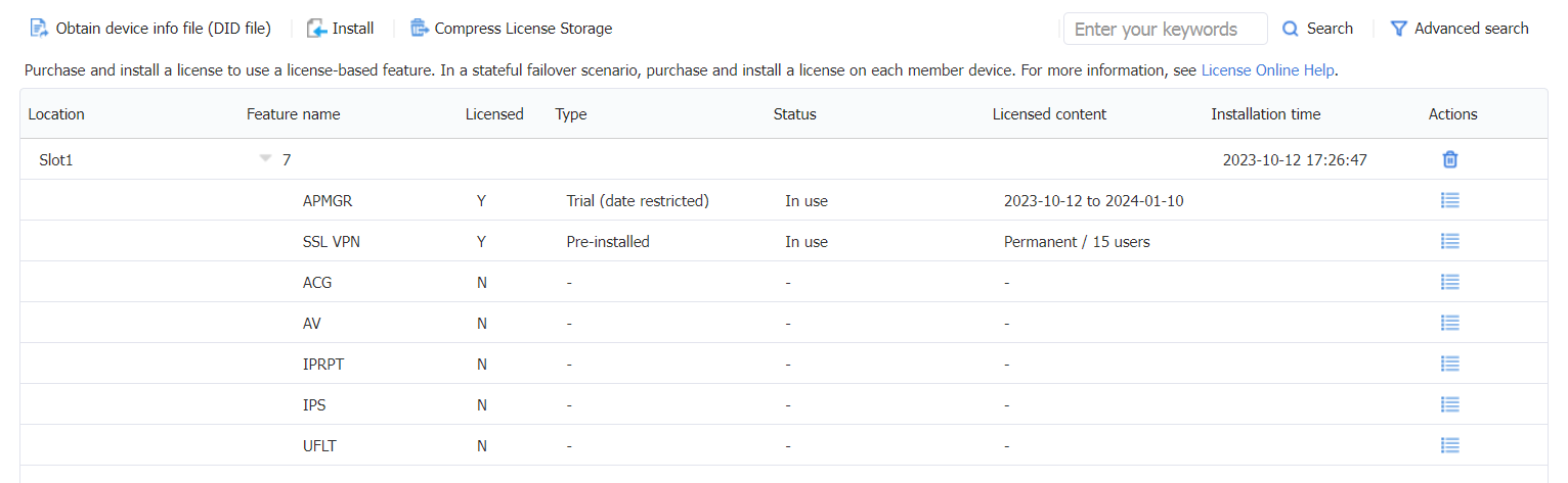
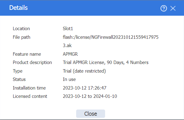
Click the Details icon in the Actions column for APMGR to view detailed license information.
Figure 50 License details
Identifying license information (CLI)
After a license is successfully registered and activated, you can use the display license feature command to check if the feature has been licensed. A value of Y means the feature has been licensed.
<FW> display license feature
Slot 1:
Total: 32 Usage: 1
Feature Licensed State
ACG N -
APMGR Y Trial
AV N -
IPRPT N -
IPS N -
SSLVPN Y Pre-licensed
UFLT N -
View detailed information about the licenses on the device by executing the display license command.
<FW> display license
Slot 1:
flash:/license/NGFirewall2023101215594179753.ak
Feature: APMGR
Product Description: Trial APMGR License, 90 Days, 4 Numbers
Registered at: 2023-10-12 17:26:47
License Type: Trial (date restricted)
Trial Validity Period: 2023-10-12 to 2024-01-10
Current State: In use
Pre-installed License
Feature: SSLVPN
Feature Description: SSLVPN License, 15 Numbers
License Type: Permanent
Current State: In use
Bulk software upgrade for APs
Automatic upgrade for APs
By default, the AP software upgrade feature is enabled on F100-C-A1/F100-C-A2. In this case, the version upgrade process of an AP is as follows:
1. The AP sends version and model information to the FW.
2. The FW compares the software version of the AP. By default, the FW compares the software version of the AP with the mappings between AP model and software and hardware versions in the APDB.
3. If the software versions are the same, the PW allows the CAPWAP tunnel establishment. If the software versions are different, inform the AP of this software version inconsistency. After receiving a message about inconsistent versions, the AP will request the version from the FW.
4. After the FW receives the version request from the AP, it sends the software version file to the AP.
5. After receiving the version file, the AP will perform a firmware upgrade and reboot, then establish a CAPWAP tunnel with the FW.
To automatically upgrade APs through the software upgrade feature, you need to upload the version files of APs to the FW and ensure that the model and version in each AP version file are consistent with those stored in the APDB.
Administrators can use the display wlan ap-model command to view the version number of the specified model in the APDB.
<FW> display wlan ap-model name WA6120X
AP model : WA6120X
Alias : WA6120X
Vendor name : H3C
Vendor ID : 25506
License weight : 100
License type : 1
Radio count : 2
Radio 1:
Mode : 802.11a, 802.11an, 802.11ac, 802.11ax
Default mode : 802.11ax
BSS count : 8
Radio 2:
Mode : 802.11b, 802.11g, 802.11gn, 802.11gax
Default mode : 802.11gax
BSS count : 8
Version Support List:
Hardware Version Ver.A:
Software Version : R2593P03
Default Software Version : A2586
Image Name : wa6500a.ipe
……
When the software version used to upgrade the AP does not match the software version corresponding to the AP model stored in the APDB, you can use the wlan apdb command to specify the software version used when the AP goes online. For more information about APDB, see the AP management configuration in WLAN Configuration Guide.
Manual upgrade for APs
After the successful establishment of the CAPWAP tunnel, you can enable the FW to deploy the version to the AP online by executing the wlan ap-image-deploy command. After the AP obtains the version sent by the FW, you can manually restart the AP to make the new version take effect. For more information about the wlan ap-image-deploy command, see AP management commands in WLAN Command Reference.
Before executing the wlan ap-image-deploy command to distribute the version to the AP, you must upload the AP version file to the FW through FTP or TFTP. The upload location is determined by the wlan image-load filepath { local | ram } command.