- Table of Contents
- Related Documents
-
| Title | Size | Download |
|---|---|---|
| 01-Text | 13.52 MB |
General safety recommendations
Examining the installation site
Installing the router in a 19-inch rack
Installing the router by using mounting brackets and a rack shelf
Installing the router by using mounting brackets and slide rails
Installing an RPE-X1/RPE-X3/RPE-X5/RPE-X5E MPU
Installing a FIP module and an air deflector
(Optional) Installing an air deflector
Installing a SAP/OAP/switching fabric module
Installing a HIM/MIM/MIC/MIC-X interface module
Assembling a MIC-X adapter module and MIC interface module into a MIC-X interface module
Installing an interface module
3 Installing optional components
Installing a fiber management tray
Installing a lightning protector for a network port
Connecting the AC power supply to a power strip with lightning protection
Connecting a serial port cable
Connecting a serial port cable
Logging in from the console port/USB console port
Connecting the console port by using a console cable
Connecting the USB console port by using a USB cable
Logging in to the router through Telnet
Replacing an RPE-X1/RPE-X3/RPE-X5/RPE-X5E MPU
Replacing a SAP/OAP/switching fabric module
Replacing a transceiver module
When to replace a memory module
7 Hardware management and maintenance
Displaying hardware information for the router
Displaying the software and hardware version information for the router
Displaying the operational statistics for the router
Displaying detailed information about a module
Displaying the electrical label information for a module
Displaying the CPU usage of a module
Displaying the memory usage of a module
Displaying the CF card information
Displaying the operational status of the fan
Displaying the operational status of power supplies
Displaying the alarming thresholds of a module
Port configuration and management
Displaying transceiver module information and alarming information
Saving the current configuration of the router
ALM LED is steady on or flashes
No response from the serial port
Dealing with console login password loss
Examining the state of password recovery capability
Skipping current system configuration
Skipping authentication for console login
Restoring to factory default configuration
Interface module, cable, and connection failure
No response from the serial port of the MPU
System software image file missing errors
1 Preparing for installation
Table1-1 shows the model and product code matrix for the H3C SR6616 router.
Table1-1 Router model and product code matrix
|
Model (on the front panel) |
Product code |
|
H3C SR6616 |
RT-SR6616-H3 |
|
RT-SR6616-DS-H3 |
Safety recommendations
To avoid any equipment damage or bodily injury caused by improper use, read the following safety recommendations before installation. Note that the recommendations do not cover every possible hazardous condition.
Safety symbols
When reading this document, note the following symbols:
![]() WARNING means an alert that calls attention to important
information that if not understood or followed can result in personal injury.
WARNING means an alert that calls attention to important
information that if not understood or followed can result in personal injury.
![]() CAUTION means an alert that calls attention to important
information that if not understood or followed can result in data loss, data
corruption, or damage to hardware or software.
CAUTION means an alert that calls attention to important
information that if not understood or followed can result in data loss, data
corruption, or damage to hardware or software.
General safety recommendations
· Keep the chassis and installation tools away from walk areas.
· Make sure the ground is dry and flat and anti-slip measures are in place.
· Remove all the external cables (including power cords) before moving the chassis.
Electricity safety
· Locate the emergency power-off switch in the room before installation. Shut the power off at once in case accident occurs.
· Make sure the router has been reliably grounded.
· Do not open or close the chassis cover when the router is powered on.
· Use an uninterrupted power supply (UPS).
· If there are two power inputs, disconnect the two power inputs to power off the router.
· Do not work alone when the router has power.
· Always verify that the power has been disconnected.
Laser safety
|
|
WARNING! · The router is a Class 1 laser device. · Disconnected optical fibers or transceiver modules might emit invisible laser light. Do not stare into beams or view directly with optical instruments when the router is operating. |
Router moving
|
|
CAUTION: Do not hold the handle of the fan tray or power supply, the handle on the rear cover of the chassis, or the air vents of chassis to move the router. Doing so might cause equipment damage or even bodily injury. |
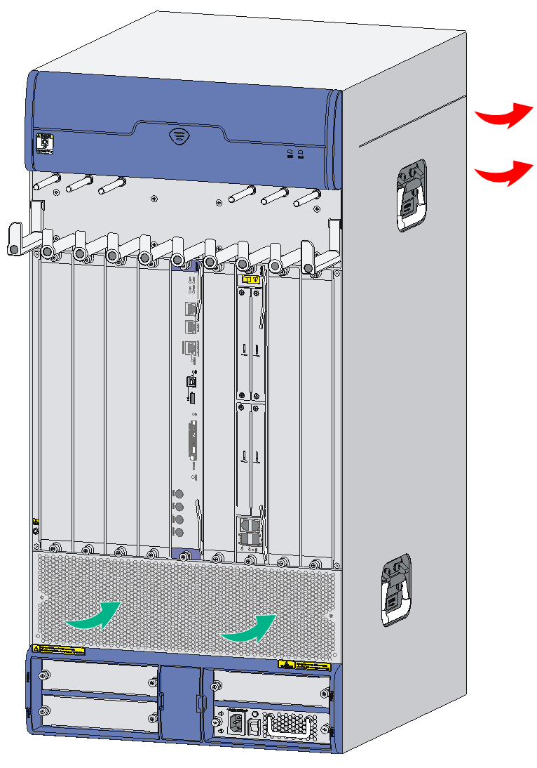
When moving the router, follow these guidelines:
· When moving the router, hold the handles at both sides of the chassis.
· Use at least two people to move the router.
· Move the router carefully.
Examining the installation site
The router can be used only indoors. For the router to operate correctly and to have a long service lifetime, make sure the installation site meets the requirements described in the following subsections.
Weight support
Make sure the floor can support the total weight of the router and accessories (such as the rack and interface modules). For the weights of the router and accessories, see H3C SR6616 Routers Hardware Information and Specifications.
Temperature
If the temperature in the equipment room is too high, too low, or changes dramatically, the router reliability will be reduced and its service lifetime will be shortened. For long-term, highly available operation of the router, make sure temperature in the equipment room meets the requirements described in Table1-2.
Table1-2 Temperature requirements
|
Item |
Temperature |
|
Operating Temperature |
0°C to 45°C (32°F to 113°F) |
|
Storage Temperature |
–40°C to +70°C (–40°F to +158°F) |
Humidity
Maintain appropriate humidity in your equipment room, as described in Table1-3.
· Lasting high relative humidity can cause poor insulation, electricity leakage, mechanical property change of materials, and metal corrosion.
· Lasting low relative humidity can cause washer contraction and ESD and bring problems including loose screws and circuit failure.
Table1-3 Humidity requirements
|
Item |
Humidity |
|
Operating humidity (noncondensing) |
10% RH to 95% RH |
|
Storage humidity (noncondensing) |
5% RH to 95% RH |
Cleanliness
Dust buildup on the chassis might result in electrostatic adsorption, which causes poor contact of metal components and contact points, especially when indoor relative humidity is low. In the worst case, electrostatic adsorption can cause communication failure.
Table1-4 Router requirement for cleanliness
|
Substance |
Particle diameter |
Concentration limit |
|
Dust particles |
≥ 0.5 µm |
≤ 1.8 × 10⁷ particles/m3 |
Corrosive gases can accelerate corrosion and aging of metal components. Make sure the corrosive gases do not exceed the concentration limits as shown in Table1-5.
Table1-5 Corrosive gas concentration limits
|
Gas |
Average concentration (mg/m3) |
Maximum concentration (mg/m3) |
|
SO2 |
0.3 |
1.0 |
|
H2S |
0.1 |
0.5 |
|
Cl2 |
0.1 |
0.3 |
|
HCI |
0.1 |
0.5 |
|
HF |
0.01 |
0.03 |
|
NH3 |
1.0 |
3.0 |
|
O3 |
0.05 |
0.1 |
|
NOX |
0.5 |
1.0 |
Cooling system
The router has a horizontally-oriented fan tray slot at the top and uses bottom to top airflow for heat dissipation.
To ensure good ventilation, the following requirements must be met:
· Leave a minimum clearance of 10 cm (3.94 in) at the inlet and outlet air vents.
· The installation site has a good cooling system.
Figure1-1 Airflow
ESD prevention
|
|
CAUTION: Make sure the resistance reading between human body and the ground is in the range of 1 to 10 megohms (Mohms). |
To prevent electrostatic discharge (ESD), note the following guidelines:
· Make sure the router and the floor are reliably grounded.
· Take dust-proof measures for the equipment room.
· Maintain the humidity and temperature in the acceptable range.
· Always wear an ESD wrist strap when touching a circuit board or transceiver module.
· Place the removed memory module, CF card, or HIM/MIM/MIC/MIC-X on an antistatic workbench, with the face upward, or put it into an antistatic bag.
· Touch only the edges, instead of electronic components when observing or moving a removed memory module, CF card, or HIM/MIM/MIC/MIC-X.
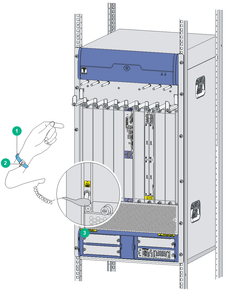
To attach the ESD wrist strap:
1. Wear the wrist strap on your wrist.
2. Lock the wrist strap tight around your wrist to keep good contact with the skin.
3. Insert the ESD wrist strap into the specially designed hole on the router chassis or attach it to the grounding screw of the chassis with the alligator clips.
4. Make sure the rack is reliably grounded.
Figure1-2 Attaching an ESD wrist strap
|
(1) ESD wrist strap |
(2) Lock |
(3) Alligator clip |
EMI
All electromagnetic interference (EMI) sources, from outside or inside of the router and application system, adversely affect the router in the following ways:
· A conduction pattern of capacitance coupling.
· Inductance coupling.
· Electromagnetic wave radiation.
· Common impedance (including the grounding system) coupling.
To prevent EMI, use the following guidelines:
· Take effective measures to filter interference from the power grid.
· Separate the grounding facility of the router from the grounding facility and lightning protection facility of the other electrical devices as far as possible.
· Use electromagnetic shielding, for example, shielded interface cables, when necessary.
Lightning protection
To protect the router from lightning better, perform the following tasks:
· Make sure the grounding cable of the chassis is reliably grounded. For information about how to connect the grounding cable, see "Grounding the router."
· Make sure the grounding terminal of the AC power receptacle is reliably grounded.
· Install a lightning protector at the input end of the power supply to enhance the lightning protection capability of the power supply.
· Install a special lightning protector at the input end of outdoor signal lines (for example, E1/T1 line) to which interface modules of the router are connected to enhance the lightning protection capability.
For more information about how to install a lightning protector and surge protector, see "Connecting the AC power supply to a power strip with lightning protection" and "Installing a surge protector."
Space
For easy installation and maintenance, follow these space requirements:
· Reserve a minimum of 1 m (3.28 ft) of clearance between the rack and walls or other devices.
· For heat dissipation, make sure the headroom in the equipment room is not less than 3 m (9.84 ft).
· Make sure the rack has enough space to accommodate the router. See Table1-6 for rack requirements. For more information about chassis dimensions, see H3C SR6616 Routers Hardware Information and Specifications.
Table1-6 Router dimensions and rack requirements
|
Model |
Chassis dimensions |
Rack requirements |
|
SR6616 AC |
· Height—886 mm (34.89 in)/20 RU · Width—436 mm (17.17 in) · Depth—591 mm (23.27 in) ¡ 480 mm (18.90 in) for the chassis ¡ 102 mm (4.02 in) for the cable management brackets at the chassis front ¡ 11 mm (0.43 in) for the grounding screw at the chassis rear |
· A minimum of 0.8 m (2.62 ft) in depth (recommended) · A minimum of 102 mm (4.02 in) between the front rack posts and the front door · A minimum of 490 mm (19.29 in) between the front rack posts and the rear door |
|
SR6616-DS |
· Height—886 mm (34.89 in)/20 RU · Width—436 mm (17.17 in) · Depth—591 mm (23.27 in) ¡ 480 mm (18.90 in) for the chassis ¡ 102 mm (4.02 in) for the cable management brackets at the chassis front ¡ 11 mm (0.43 in) for the grounding screw at the chassis rear |
· A minimum of 0.8 m (2.62 ft) in depth (recommended) · A minimum of 102 mm (4.02 in) between the front rack posts and the front door · A minimum of 490 mm (19.29 in) between the front rack posts and the rear door |
|
|
NOTE: The signal cables and power cords are routed through the front of the chassis. If you use power cords that has a conductor cross-section area of a minimum of 16 sq mm (0.02 sq in), leave more space between the front rack posts and the front door as appropriate. |
Power supply
· Make sure the power supply system at the installation site is stable and meets the requirements of the power supplies, including the rated input voltage.
· Select power supplies based on the power consumption of the cards and fan trays. For more information about system power consumption and technical specifications of power supplies, see H3C SR6616 Routers Hardware Information and Specifications.
Installation accessories
|
|
|
|
|
|
Grounding cable |
ESD wrist strap |
Cable tie |
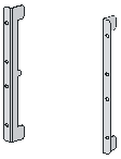
Mounting brackets |
|
|
|
|
|
|
M6 screws (provided with the SR6616-DS and user-supplied for other router models) |
Cage nuts (provided with the SR6616-DS and user-supplied for other router models) |
|
|
Pre-installation checklist
Table1-7 Pre-installation checklist
|
Item |
Requirements |
Result |
|
|
Installation site |
Ventilation |
· There is a minimum clearance of 10 cm (3.9 in) around the inlet and outlet vents for heat dissipation of the router chassis. · A ventilation system is available at the installation site. |
|
|
Temperature |
0°C to 45°C (32°F to 113°F) |
|
|
|
Relative humidity |
10% to 95% (noncondensing) |
|
|
|
Cleanliness |
· Dust concentration ≤ 1.8 × 10⁷ particles/m3. · No dust on desk within three days |
|
|
|
ESD prevention |
· The equipment and floor are reliably grounded. · The equipment room is dust-proof. · The humidity and temperature are in the acceptable range. · Wear an ESD wrist strap and uniform when touching a circuit board. · Place the removed memory module, CF card, or HIM/MIM/MIC/MIC-X on an antistatic workbench, with the face upward, or put it into an antistatic bag. · Touch only the edges, instead of electronic components when observing or moving a removed memory module, CF card, or HIM/MIM/MIC/MIC-X. |
|
|
|
EMI prevention |
· Take effective measures to filter interference from the power grid. · Separate the grounding facility of the router from the grounding facility and lightning protection facility of the other electrical devices as far as possible. · Keep the router far away from radio stations, radar and high-frequency devices working in high current. · Use electromagnetic shielding when necessary. |
|
|
|
Lightning protection |
· The grounding cable of the chassis is reliably grounded. · The grounding terminal of the AC power receptacle is reliably grounded. · A port lightning arrester is installed. (Optional) · A power lightning arrester is installed. (Optional) · A signal lightning arrester is installed at the input end of an external signal cable. (Optional) |
|
|
|
Electricity safety |
· Equip an uninterrupted power supply (UPS). · In case of emergency during operation, switch off the external power switch. |
|
|
|
Workbench |
· The workbench is stable enough · Well grounding |
|
|
|
Rack-mounting requirements |
· Install the router in an open rack if possible. If you install the router in a closed cabinet, make sure the cabinet is equipped with a good ventilation system. · The rack is sturdy enough to support the weight of the router and installation accessories. · The size of the rack is appropriate for the router. · The front and rear of the rack are a minimum of 0.8 m (31.50 in) away from walls or other devices. |
|
|
|
Safety precautions |
· The router is far away from any moist area and heat source. · The emergency power switch in the equipment room is located. |
|
|
|
Tools |
· Installation accessories supplied with the router · User supplied tools |
|
|
|
Reference |
· Documents shipped with the router · Online documents |
|
|
2 Installing the router
|
|
IMPORTANT: Keep the packages of your router and its accessories safe for future use. |
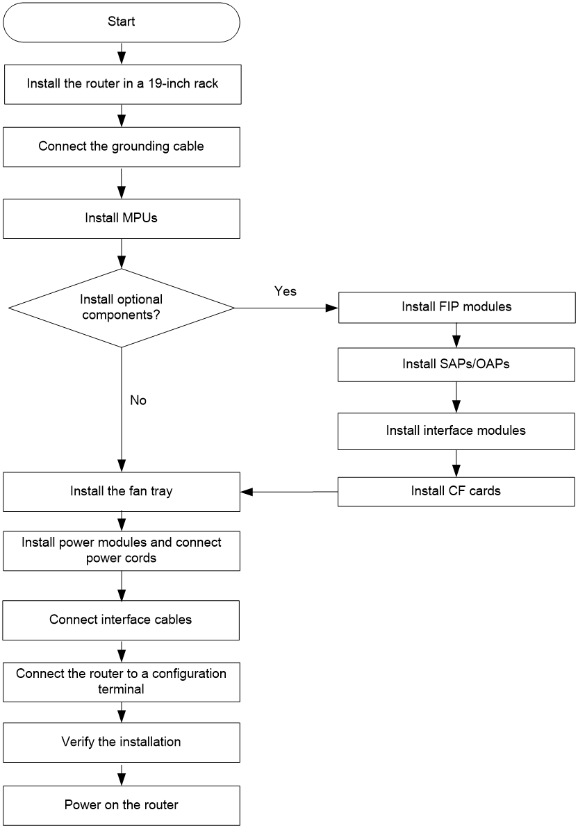
Figure2-1 Router installation flow
Check before installation
To prepare for installing the router:
· Make sure you have read "Preparing for installation" carefully and the installation site meets all the requirements.
· Prepare a 19-inch rack. For more information about how to install a rack, see the installation guide provided with the rack.
· Make sure the rack is sturdy and securely grounded.
· Make sure there is sufficient clearance around the rack for heat dissipation and installation.
· Make sure there is no debris inside or around the rack.
· Move the router to a place near the rack.
Installing the router in a 19-inch rack
You can install the router in a rack by using mounting brackets and a rack shelf or using mounting brackets and slide rails. Select an installation method as required.
Installing the router by using mounting brackets and a rack shelf
Attaching cage nuts to the rack
1. Determine where to install the router in the rack, and then install a rack shelf on the rack.
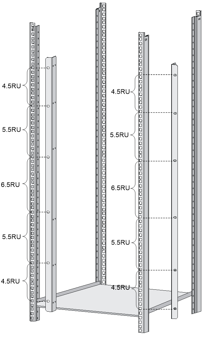
2. As shown in Figure2-2, mark the positions of cage nuts on the front rack posts by using a front mounting bracket according to the position of the rack shelf.
Figure2-2 Marking the positions of the cage nuts
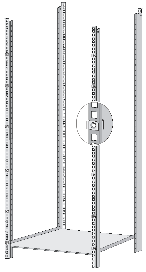
3. As shown in Figure2-3, attach the cage nuts to the marked positions on the rack posts.
Figure2-3 Installing cage nuts
Installing the cable management brackets
As shown in Figure2-4, before attaching a mounting bracket to the router, attach the cable management bracket to the left mounting bracket with screws.
Figure2-4 Installing the cable management bracket
Attaching the mounting brackets to the router
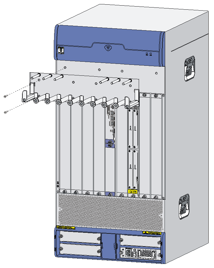
Before installing the router in a rack, install the front mounting brackets to the two sides of the router.
To attach the front mounting brackets to the router, align the screw holes on the mounting brackets with the screw holes on the router chassis, and then fasten the screws.
Figure2-5 Attaching the front mounting brackets to the two sides of the router
Installing the router in the rack
|
|
IMPORTANT: If you have ordered an air filter for the router, attach it to the router before rack-mounting the router. For the air filter installation procedure, see "Installing an air filter." |
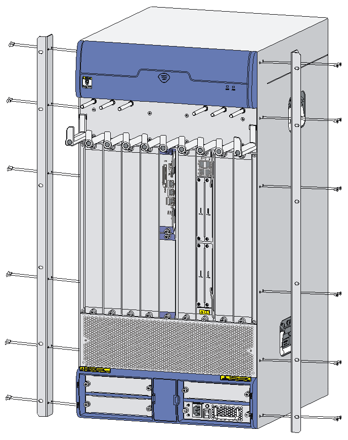
1. Put the router on the rack shelf, and slide the router into the rack, making sure that there is enough clearance between the router and rack posts for installing the mounting brackets.
Figure2-6 Installing the router in the rack
Installing the router by using mounting brackets and slide rails
The procedure is similar for installing the router by using mounting brackets and slide rails and by using mounting brackets and a rack shelf. For more information, see "Installing the router by using mounting brackets and a rack shelf."
Before installing the router in the rack, attach slides rails to the rack. As a best practice, purchase slide rails from H3C. Table2-1 describes the slide rails available for the router. For information about installing the slide rails, see the installation guide shipped with the slide rails.
If the rack has slide rails installed, skip this step.
|
|
IMPORTANT: Select slide rails for the router based on the total chassis weight. |
Table2-2 Slide rails available for the router
|
Router model |
Chassis weight (fully configured) |
Available slide rails |
||||
|
Slide rail model |
Max. load-bearing capacity |
Adjustment range |
Occupied space |
Remarks |
||
|
SR6616/SR6616-DS |
102 kg (224.87 lb) |
LSXM1BSR |
450 kg (992.06 lb) |
630 to 900 mm (24.80 to 35.43 in) |
1 RU |
Select one of the slide rail models |
|
LSTM1KSGD0 |
280 kg (617.28 lb) |
300 to 500 mm (11.81 to 19.69 in) |
2 RU |
|||
|
LSTM2KSGD0 |
360 kg (793.65 lb) |
500 to 800 mm (19.69 to 31.50 in) |
2 RU |
|||
Grounding the router
|
|
WARNING! Correctly connecting the router grounding cable is crucial to lightning protection and EMI protection. |
To connect the grounding cable:
1. Remove the grounding screws from the grounding terminal on the rear panel of the router chassis.
2. Use the grounding screws to attach the lug of the grounding cable to the grounding terminal and fasten the screws.
3. Connect the other end of the grounding cable to the grounding strip of the rack.
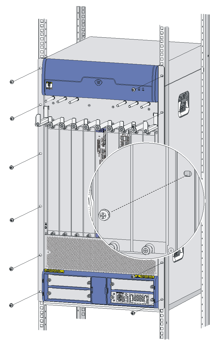
Figure2-7 Connecting the grounding cable to the grounding hole of router
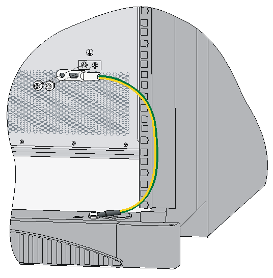
|
|
NOTE: · Make sure the resistance reading between router chassis and the ground is smaller than 5 ohms. · To guarantee the grounding effect, use the grounding cable provided with the router to connect to the grounding strip in the equipment room as long as possible. |
Installing an MPU
|
|
CAUTION: · When the router is installed with two MPUs, the standby MPU is hot swappable. When the router is installed with one MPU, the MPU is not hot swappable. · To avoid hardware damage, do not hot swap a FIP or SAP/OAP during the booting process of an MPU (with the RUN LED fast flashing). |
When two MPUs are installed on the router, the ACT LED on the active MPU is steady green. For the MPU LED descriptions, see H3C SR6616 Routers Hardware Information and Specifications.
Installing an RPE-X1/RPE-X3/RPE-X5/RPE-X5E MPU
Before installing an RPE-X1, RPE-X3, RPE-X5, or RPE-X5E MPU, install a compatible carrier in the MPU slot. The RPE-X1 MPU supports the BKEB carrier, the RPE-X3 MPU supports the BKEC carrier, and the RPE-X5/RPE-X5E MPU supports the BKEE carrier. For the carrier model, see the barcode on the carrier.
The installation procedures for the RPE-X1, RPE-X3, RPE-X5, and RPE-X5E are the same. This example uses an RPE-X1.
To install an RPE-X1 MPU:
1. Locate the slot to install the RPE-X1 MPU.
The RPE-X1 MPU can be installed in slot 4 or slot 5. This procedure uses slot 4 as an example.
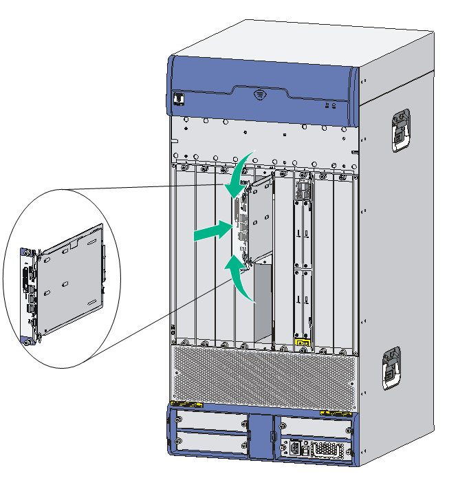
2. Gently push the RPE-X1 carrier (with the components facing up) into slot 4 along the slide rails until the positioning pins on the backplane are seated in the positioning holes at the bottom of the RPE-X1 carrier. Then push the ejector levers inward to lock the RPE-X1 carrier in position and fasten the captive screws on the ejector levers.
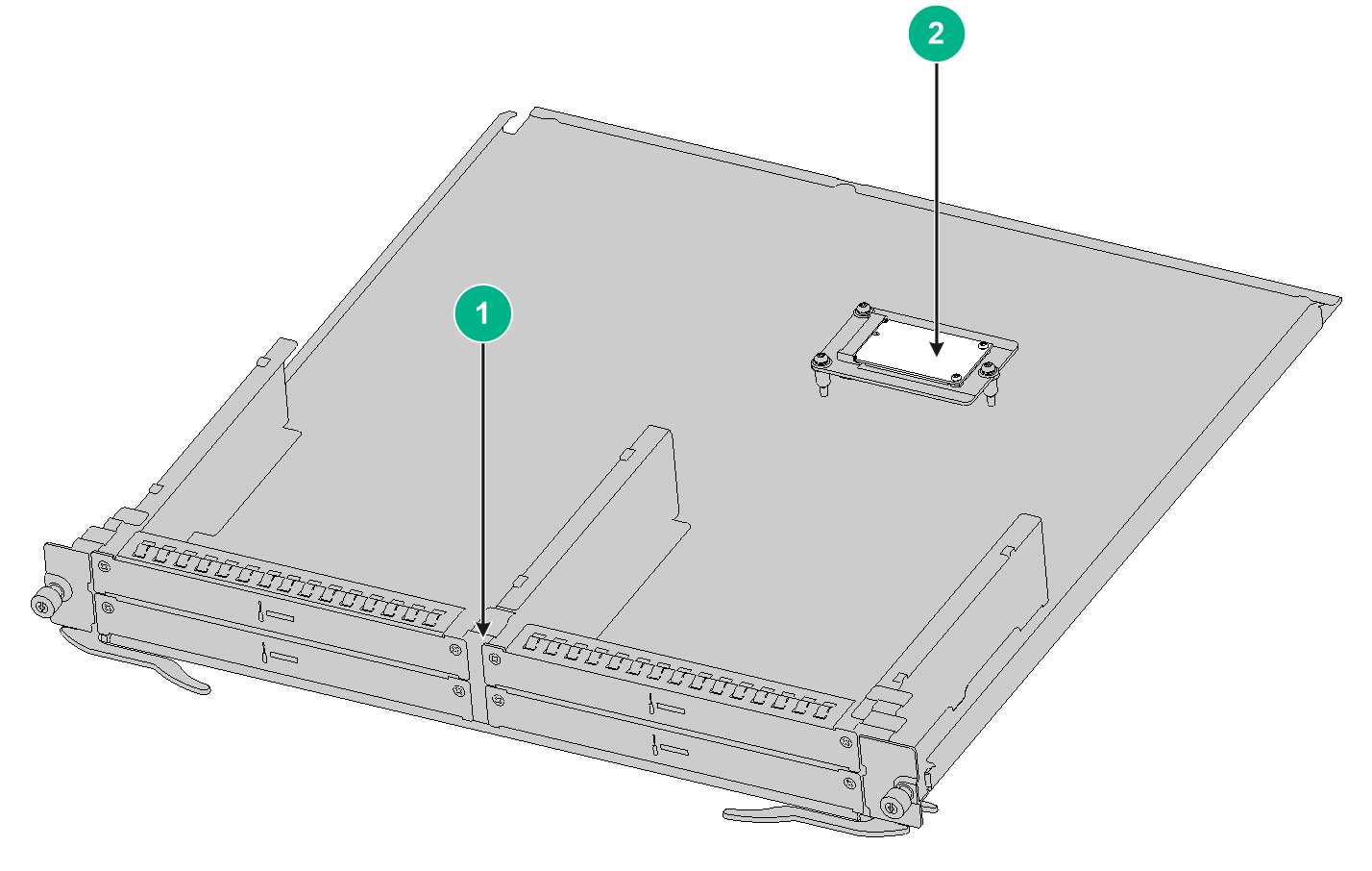
Figure2-8 Internal structure of the RPE-X1 carrier
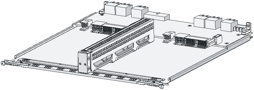
Figure2-9 Installing the RPE-X1 carrier
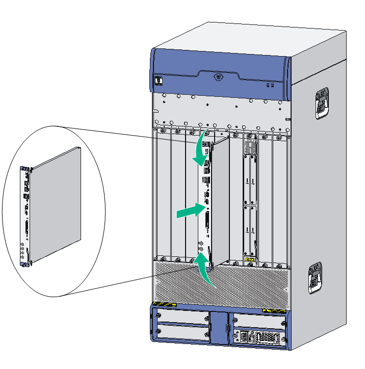
3. Use even pressure to gently push the RPE-X1 into slot 4 along the slide rails, and then push the ejector levers inward to lock the RPE-X1 in position.
Figure2-10 Inserting the RPE-X1 into the slot
4. Fasten the captive screws on the RPE-X1.
5. Observe the RUN LED on the RPE-X1 to verify that the RPE-X1 is installed correctly.
After the router is powered on, the RUN LED on the RPE-X1 flashes green at 8 Hz until the application software is loaded. When the RUN LED flashes green at 1 Hz, the RPE-X1 is operating correctly.
Installing an RSE-X1 MPU
1. Locate the slot to install the RSE-X1.
You can install an RSE-X1 in slot 5 or slot 6. This procedure uses slot 5 as an example.
2. Loosen the captive screws on the filler panel in slot 5, and then remove the filler panel
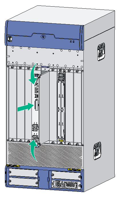
3. Use even pressure to gently push the RSE-X1 into slot 5 along the slide rails, and then push the ejector levers inward to lock the RSE-X1 in position.
Figure2-11 Inserting the RSE-X1 into the slot
4. Fasten the captive screws on the RSE-X1.
5. Observe the RUN LED on the RSE-X1 to verify that the RSE-X1 is installed correctly.
After the router is powered on, the RUN LED on the RSE-X1 flashes green at 8 Hz until the application software is loaded. When the RUN LED flashes green at 1 Hz, the RSE-X1 is operating correctly.
Installing an MCP MPU
|
|
IMPORTANT: An MCP MPU supports only FIP-10 and FIP-20 modules. |
You can install an MCP in slot 5 or slot 6. The installation procedure is similar for MCPs. The following procedure installs an MCP-X1 in slot 5.
To install an MCP:
1. Loosen the captive screws on the filler panel in slot 5, and then remove the filler panel.
2. Use even pressure to gently push the MCP into slot 5 along the slide rails until positioning pins on the backplane are seated in the positioning holes, and then push the ejector levers inward to lock the MCP in position.
Figure2-12 Inserting the MCP into the slot
3. Fasten the captive screws on the MCP.
4. Observe the RUN LEDs on the MCP to verify that the MCP is installed correctly.
After the router is powered on, the RUN LED on the MCP flashes green at 8 Hz until the application software is loaded. When the RUN LED flashes green at 1 Hz, the MCP is operating correctly.
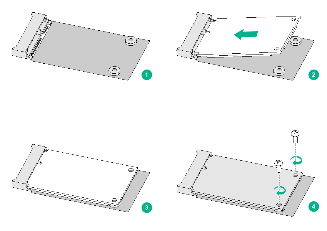
Installing an SSD drive
Only the RPE-X5E, FIP-260, FIP-380, and SAP-XP4GE32 modules support mSATA SSD drives (the router does not support SSC-enabled SSD drives).
No SSD drive or screws are provided with the router. Prepare them yourself as required. For correct operation of the device, use H3C SSD drives.
To install an SSD drive:
1. Locate the SSD drive slot on the service module.
Figure2-13 Service module structure (FIP-260)
|
(1) Front panel |
(2) SSD drive slot |
2. Align the golden plating on the SSD drive with the mSATA connector in the slot.
3. Slightly press the SSD drive until it is level with the surface of the connector.
4. Use a Phillips screwdriver to screw the SSD drive into place.
Figure2-14 Installing an SSD drive
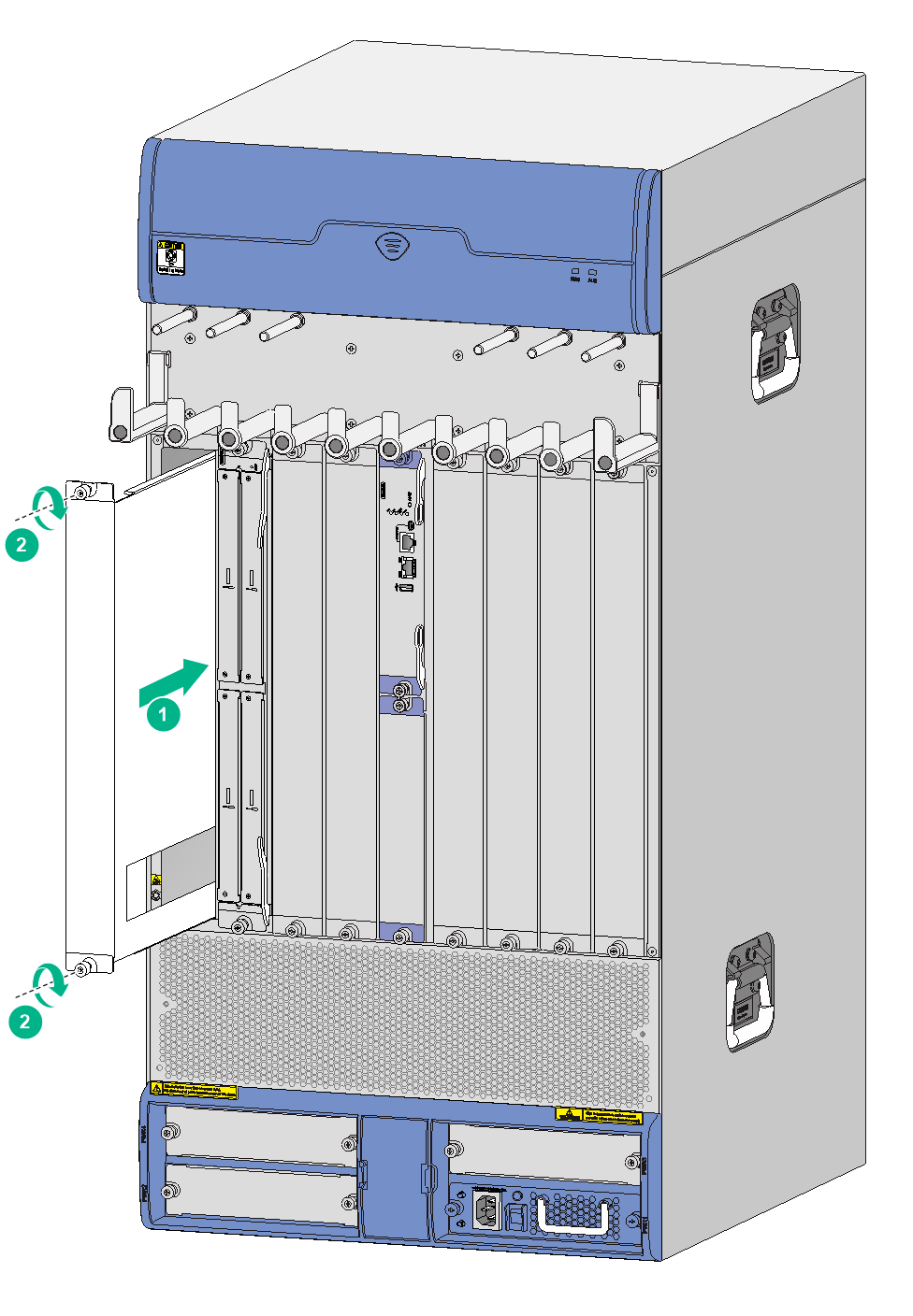
Installing a FIP module and an air deflector
Installing a FIP module
|
|
IMPORTANT: FIP-10 and FIP-20 can operate correctly only on a router installed with an MCP. |
The router supports hot swapping of FIP modules.
The installation procedure is similar for FIPs. The following procedure installs a FIP-210.
To install a FIP module:
1. Locate the slot to install the FIP module.
2. Remove the captive screws on the filler panel, and then remove the filler panel.
3. Use even pressure to gently push the FIP module into the slot along the slide rails until positioning pins are seated in the positioning holes in the backplane, and then push the ejector levers inward to lock the FIP module in position.
If you encounter a resistance when pushing a FIP module into slot, remove the filler panels from the left and right slots and then install the FIP module. After the FIP module is installed, reinstall the removed filler panels to prevent dust from entering the chassis.
Figure2-15 Inserting a FIP module
4. Fasten the captive screws on the FIP module.
5. Observe the RUN LED on the FIP to verify that the FIP module is installed correctly.
After the router is powered on, the RUN LED on the FIP flashes green once and then fast flashes (at 8 Hz) until the application software is loaded. When the RUN LED flashes green at 1 Hz, the FIP is operating correctly.
For the FIP LED descriptions, see H3C SR6616 Routers Hardware Information and Specifications
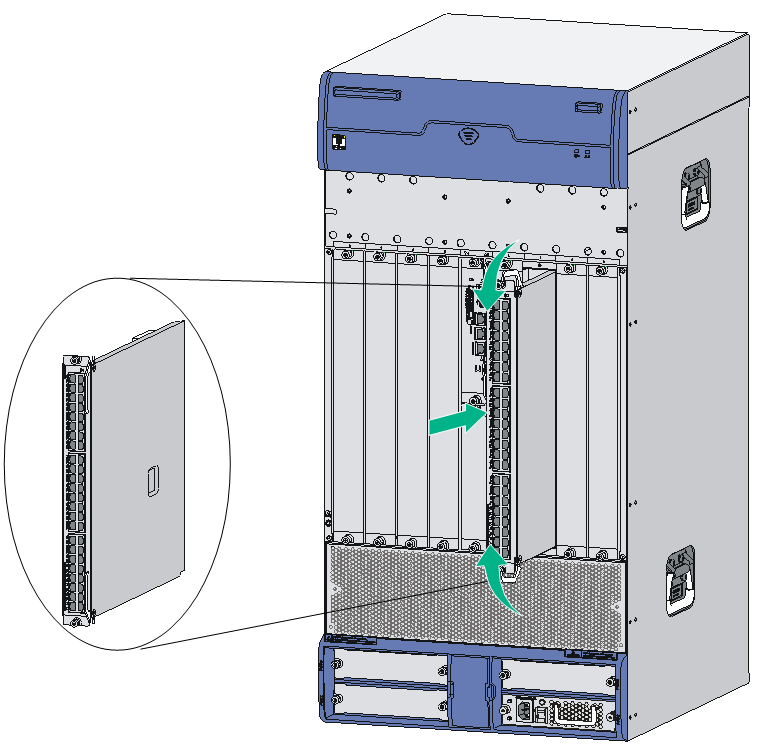
(Optional) Installing an air deflector
For a FIP-660, if a service module slot adjacent to the FIP-660 is empty, install an air deflector over the slot.
To install an air deflector:
1. Locate the service module slot to install the air deflector.
2. Loosen the captive screws on the filler panel, and then remove the filler panel.
3. Gently push the air deflector into the service slot along the slide rails until it snaps into the place.
4. Fasten the captive screws on the air deflector.
Figure2-16 Installing an air deflector
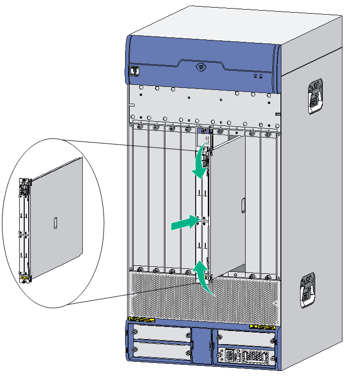
Installing a SAP/OAP/switching fabric module
The router supports hot swapping of SAPs, OAPs, and switching fabric modules.
The installation procedure is similar for SAPs, OAPs, and switching fabric modules. The following procedure installs a SAP module.
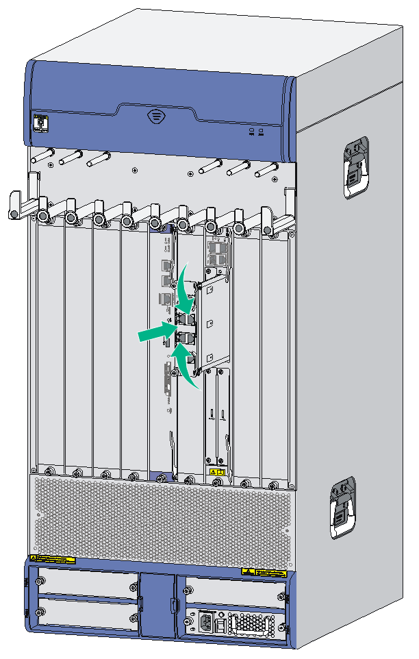
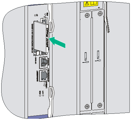
To install a SAP module:
1. Locate the slot to install the SAP module.
2. Loosen the captive screws on the filler panel, and then remove the filler panel.
3. Use even pressure to gently push the SAP module into the slot along the slide rails until the positioning pins on the backplane are seated in the positioning holes, and then push the ejector levers inward to lock the SAP module in position.
Figure2-17 Inserting a SAP module
4. Fasten the captive screws on the SAP module.
5. Observe the RUN LED on the SAP module to verify that the SAP module is installed correctly.
After the router is powered on, the RUN LED on the SAP flashes green once and then fast flashes (at 8 Hz) until the application software is loaded. When the RUN LED flashes green at 1 Hz, the SAP is operating correctly.
Installing a HIM/MIM/MIC/MIC-X interface module
|
|
CAUTION: · MIM interface modules are not hot swappable. MIC interface modules are hot swappable. · All MIC-X interface modules except the MIC-X-CNDE-SJK are hot swappable. To remove a MIC-X-CNDE-SJK interface module when the router is operating, press the REMOVE button on the interface module until its RUN LED turns off. · HIM interface modules can be hot swapped. To remove a HIM interface module when the router is operating, first execute the remove command for the interface module. · To avoid hardware damage, when the RUN LED on a FIP module is fast flashing green, do not install or remove a HIM/MIM/MIC/MIC-X module on it. |
Assembling a MIC-X adapter module and MIC interface module into a MIC-X interface module
|
|
IMPORTANT: A MIC-X-ET16-compatible FIP module supports only one MIC-X-ET16 assembled by a MIC-X adapter module and a MIC-ET16L interface module. |
MIC-X adapter module components
Figure2-18 Screw
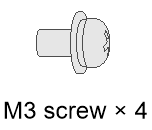
Figure2-19 Carrier
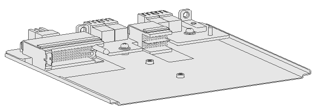
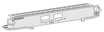
Figure2-20 Front panel
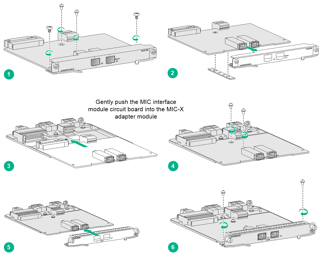
Assembling a MIC-X adapter module and MIC interface module into a MIC-X interface module
1. Use a screwdriver to remove the four screws from the MIC interface module circuit board so that the front panel and the gasket are disengaged from the circuit board.
2. Align the MIC interface module circuit board with the guide rails on the MIC-X adapter module carrier. Gently push the circuit board into the carrier along the guide rails until the circuit board makes close contact with the connectors on the MIC-X adapter module carrier.
3. Install M3 screws provided with the MIC-X adapter module carrier into the two screw holes at the center of MIC interface module circuit board and fasten the screws.
4. Select the front panel matching the MIC interface module, align the front panel with the ports on the circuit board, and use M3 screws to attach the front panel to the circuit board.
The MIC-CLP2L, MIC-CLP4L, MIC-SP4L, MIC-SP8L, MIC-ET16L interface modules can be assembled into corresponding MIC-X modules by using MIC-X adapter modules.
Installing an interface module
The installation procedure is the same for HIM, MIM, MIC, and MIC-X interface modules.
To install a HIM/MIM/MIC/MIC-X interface module:
1. Locate the slot to install the HIM/MIM/MIC/MIC-X on the FIP module.
2. Loosen the captive screws on the filler panel, and then remove the filler panel.
Keep the filler panel safe for future use.
3. Use even pressure to push the HIM/MIM/MIC/MIC-X slowly along the slide rails into the slot, and then close the ejector levers inward.
Install a HIM/MIM/MIC-X with its PCB components facing right and install a MIC with its PCB components facing left.
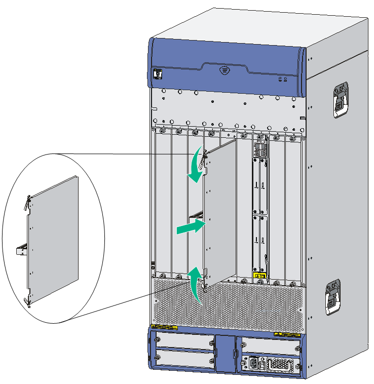
Figure2-22 Installing a HIM/MIM/MIC/MIC-X
4. Fasten the captive screws on the HIM/MIM/MIC/MIC-X.
5. Observe the LED for the slot on the router front panel to verify that the HIM/MIM/MIC/MIC-X is installed correctly.
If the LED is on after the HIM/MIM/MIC/MIC-X initialization completes, the HIM/MIM/MIC/MIC-X has been installed correctly and is operating correctly. If the LED is Off, the HIM/MIM/MIC/MIC-X has failed the POST.
Installing a fan tray
The router supports hot swapping of fan trays. The fan trays can automatically adjust the fan speed.
To install a fan tray:
1. Orient the fan tray to make sure the warning sign on the front panel is on the left.
2. Pressing the release button on the fan tray with your thumb, and supporting the fan tray bottom with the other hand, gently push the fan tray along the slide rails into the slot until the fan tray keeps in close contact with the backplane of the router. (see Figure2-23.)
Figure2-23 Pushing the fan tray into the slot

3. Power on the router and check the status LED on the front panel.
On means the fan tray is operating correctly. Off means the fan tray has failed the POST. For the LED description of the fan tray, see H3C SR6616 Routers Hardware Information and Specifications.
Installing a CF card
To install a CF card on an MCP, remove the CF card cover first.
1. Push the CF card eject button all the way into the slot, and make sure the button does not project from the panel.
2. Insert the CF card into the slot following the direction shown in Figure2-24, and make sure it does not project from the slot.
Figure2-24 Inserting the CF card into the slot
|
|
NOTE: If the boot file of the router is stored in the CF card, before booting the router, make sure the CF card has been correctly installed. Otherwise, the router cannot be booted. |
Installing a power supply
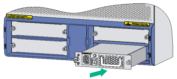
The procedures for installing an AC power supply and DC power supply are the same. The following uses a PSR650-A AC power supply as an example.
1. Locate the slot to install the power supply. Use even pressure to gently push the power supply slowly along the slide rails into the slot.
Figure2-25 Inserting the power supply into the slot
2. Fasten the captive screws on the power supply.
3. After connecting the power cord, power on the power supply. If the power supply LED is green, the power supply operates correctly. If the LED is red, the power supply has failed.
For more information about the power supply LEDs, see H3C SR6616 Routers Hardware Information and Specifications.
Connecting a power cord
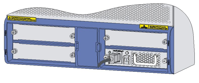
Connecting an AC power cord
1. Make sure the router is reliably grounded, and the power switch on the router is in the OFF position.
2. Connect one end of the AC power cord to the AC receptacle on the router, and the other end to the AC power source.
3. Attach the power cord to the power supply handle by using a cable tie.
Figure2-26 Connecting an AC power cord to the router
Connecting a DC power cord
Connecting the power cord for the PSR650-D
Figure2-27 DC power cord
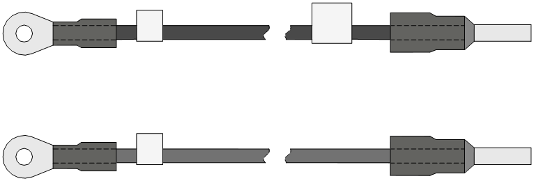
Connecting a DC power cord
|
|
WARNING! Identify the label on the DC power cord when connecting a DC power cord to avoid connection mistakes. |
To connect a DC power cord:
1. Switch off the DC power supply.
2. Remove the protection cover of the DC power supply.
3. Remove the screws from the terminals on the power supply.
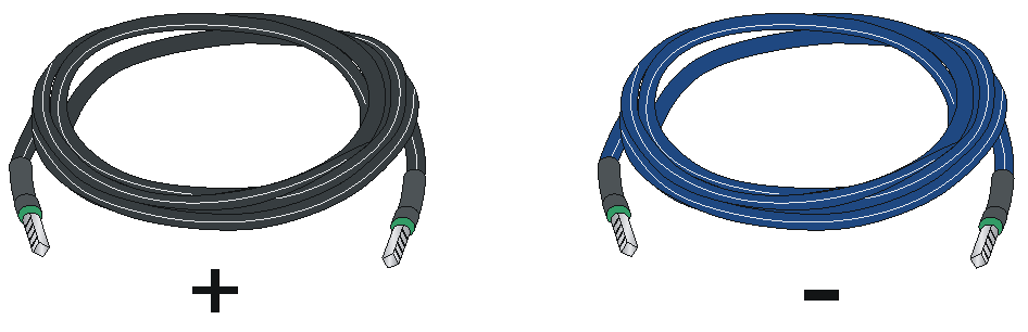
4. Connect the end marked with "–" of the supplied blue DC power cord to the negative terminal (–) on the power supply and fasten the screw.
5. Connect the end marked with "+" of the supplied black DC power cord to the positive terminal (+) on the power supply and fasten the screw.
6. Connect the other end of the DC power cord to the DC power source.
7. Install the protection cover of the DC power supply.
Figure2-28 Connecting the DC power cord

Connecting the power cord for the PSR1200-D
Figure2-29 DC power cord
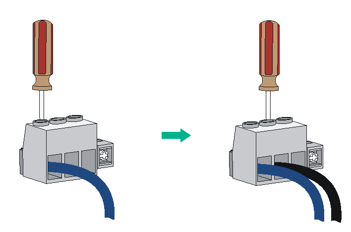
To connect the DC power cord:
1. Loosen the captive screws on the power supply to remove the power supply connector.
2. Connect the end marked with "– "to the negative terminal (–) on the power supply and fasten the screw.
3. Connect the end marked with "+"to the positive terminal (+) on the power supply and fasten the screw.
Figure2-30 Attaching the power cords to the power supply connector
4. Insert the power supply connector in right direction into the power supply, and fasten the captive screws.
Figure2-31 Installing the power supply connector to the power supply
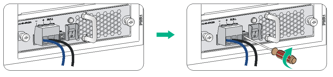
5. Connect the other ends of the power cords to the DC power source.
3 Installing optional components
Optional components are not provided with the router. Purchase them as needed.
Installing an air filter
To install an air filter, align the positioning pins on the air filter with the screw holes near the air intake vents, and fasten the fastening screws on the air filter.
Figure3-1 Installing the air filter slide rails
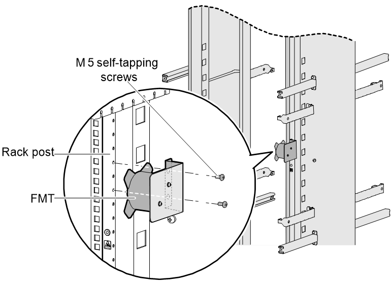
Installing a fiber management tray
Preparations
Confirm the following prerequisites:
· The rack is fixed.
· The router is installed.
The installation involves the following materials:
· Fiber management tray (FMT)
· M5×10 self-tapping screws (two screws for one FMT)
Installation procedure
To install an FMT:
1. Align the FMT and the installation holes on the rack post.
2. Use two M5×10 self-tapping screws to secure each FMT into place.
Installing a lightning protector for a network port
|
|
IMPORTANT: · Lightning protectors are applicable to only 10/100 Mbps copper Ethernet ports. · Read the instructions for the lightning protector carefully before you install it. · The router does not come with any lightning protector. |
If part of the network cable of a copper Ethernet port must be routed outdoors, connect a lightning protector to the cable before you plug the cable into the port. The router provides this type of lightning protector: single port, residual pulse energy (8/20μs test pulse) 5 KA, output voltage (10/700μs waveform): core-core ≤ 40 V, core-ground ≤ 600 V.
Installation procedure
1. Use a double-faced adhesive tape to stick the lightning protector onto the router chassis, and make sure it is as close to the grounding screw of the router as possible.
2. Measure the distance between the protector and the grounding screw of the router, cut the ground wire of the protector as appropriate, and securely tighten the ground wire to the grounding screw of the router.
3. Use the multimeter to measure whether the ground wire of the protector contacts well with the grounding screw of chassis.
4. Insert the outdoor network cable into the protector's IN end, and the cable connected to the router into the OUT end, and look at the indicators on the lightning protector to verify that the connection is correct.
5. Use nylon ties to bundle the cables neatly.
Figure3-3 Installing a lightning protector for a network port
|
(1) Lightning protector |
(2) Grounding cable |
Installation precautions
The performance of the port lightning protector might be affected in the following cases:
· The port lightning protector is installed in reverse direction. Connect the IN end to the outdoor network cable and the OUT end to the network port on the router.
· The port lightning protector is not reliably grounded. After the connection, use the multimeter to confirm that the ground wire for the protector is as short as possible to ensure its good contact with the grounding screw of the router.
· The installed port lighting protectors are not sufficient. If the router has more than one network port connected with other devices through cables outdoor, install a lightning protector for each network port.
Connecting the AC power supply to a power strip with lightning protection
|
CAUTION: Make sure the PE terminal of the power socket has been securely grounded. |
If part of the AC power line is routed outdoors, use a power strip with lightning protection to connect the AC power cord of the router to the AC power line to protect the router from being damaged by lightning strikes.
You can attach the power strip to the rack, workbench, or wall of equipment room.
After you connect the AC power cord from the router to a socket on the power strip, verify that the green RUN LED on the strip is on and the red LED is off.
If the red LED is on, use a multimeter to check the polarity of the wires in the power socket for wrong connections. If the zero wire (left) and the live wire (right) are correctly connected, check for missing grounding connection.
Figure3-4 Power strip with lightning protection
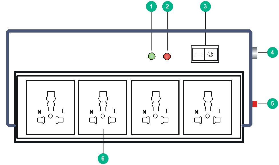
|
(1) Working LED (green) |
On means the circuit is operating correctly; off means the circuit is damaged. |
|
(2) Grounding/pole detection LED (red) |
On indicates a wrong wire connection (the wire is not grounded or the live line and null line are reversely connected), and you need to check the power supply line. |
|
(3) Power switch |
|
|
(4) IEC standard socket |
It is used to connect to the power supply in the equipment room through a power cord. |
|
(5) Overload automatic protector |
The protector automatically opens the electric circuit when the current exceeds the threshold and closes the electric circuit when the current drops below the threshold. |
|
(6) Multifunctional socket |
It is used to connect the power supply of the router. |
Installing a surge protector
|
|
CAUTION: Ground the surge protector as near as possible. The grounding resistance must be less than 4 ohms. The grounding resistance must be less than 1 ohm if there are special grounding requirements. |
Generally, you need to connect a surge protector before connecting a signal cable to the router. This can protect electronic devices against surge over-voltage resulting from lightning strokes and other interferences, and minimize impact on the router.
The surge protector is serially connected to a signal cable, so the surge protector must satisfy the requirements of network performance indexes such as data transmission bandwidth, as well as the lightning protection performance requirement. Before installing a surge protector, consider such performance indexes of the surge protector as lightning protection, bandwidth, transmission loss, and port type.
The router supports the following types of surge protectors:
· Surge protector—Maximum discharge current 2.5KA/protection voltage 25V--SMB-75J/ SMB-75J-1W-10Mbps
· Surge protector—Maximum discharge current 2.5KA/protection voltage 25V-BNC-75K/ BNC-75K-10Mbps
· Surge protector (U port)—Maximum discharge current 3KA/common-mode 400V/differential mode 170V-RJ11
To install a surge protector:
1. Use a double-faced adhesive tape to stick the surge protector onto the router chassis, and make sure it is as close to the grounding screw of the router as possible.
2. Measure the distance between the protector and the grounding screw of the router, cut the ground wire of the protector as appropriate, and securely tighten the ground wire to the grounding screw of the router.
3. Use the multimeter to measure whether the ground wire of the protector contacts well with the grounding screw of chassis.
4. Insert the outdoor network cable into the protector's IN end, and the cable connected to the router into the OUT end, and look at the indicators on the surge protector to verify that the connection is correct.
5. Use nylon ties to bundle the cables neatly.
|
|
NOTE: Read the instructions carefully before installing the surge protector. |
Figure3-5 Installing a surge protector
Precautions
The performance of the surge protector might be affected in the following cases:
· The surge protector is installed in reverse direction. Connect the IN end to the outdoor network cable and the OUT end to the network port on the router.
· The surge protector is not reliably grounded. After the connection, use the multimeter to confirm that the ground wire for the protector is as short as possible to ensure its good contact with the grounding screw of the router.
· The installed surge protectors are not sufficient. If the router has more than one cable connected with other devices through cables outdoor, install a surge protector for each cable.
4 Connecting interface cables
Connecting the AUX cable
Overview
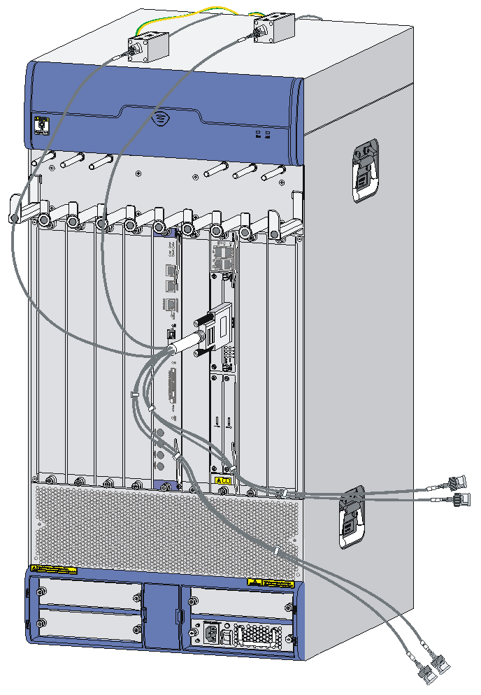
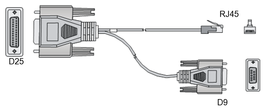
An AUX console cable is an 8-core shielded cable, with a crimped RJ-45 connector at one end for connecting to the AUX port of the router, and DB-25 and DB-9 male connectors at the other end for connecting to the serial port of the modem.
Figure4-1 AUX cable
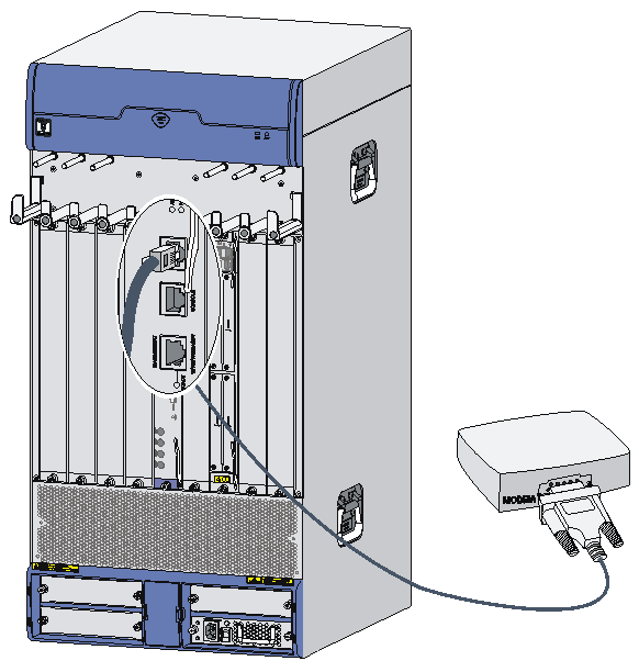
Connecting the AUX cable
1. Plug the DB-9 or DB-25 male connector at one end of the AUX cable into the serial port of the modem.
2. Plug the RJ-45 connector of the AUX cable into the AUX port of the router.
Figure4-2 Connecting the AUX port to a modem
Connecting an Ethernet cable
Overview
10/100 Mbps Ethernet uses category-5 twisted pair cables, while 1000 Mbps Ethernet uses category-5 enhanced or category-6 twisted pair cables. Twisted pair cables include straight-through cables and crossover cables.
Category-5 cables provide a transmission frequency of 100 MHz for voice and data transmission; they are mainly used in 100Base-T and 10Base-T networks. Category-5 cables are common Ethernet cables, which can also be used to transmit 1000 Mbps Ethernet data.
Category-5 enhanced cables feature low attenuation and crosstalk, providing higher attenuation to crosstalk ratio (ACR), less delay error and higher performance than category-5 cables. Category-5 enhanced cables are mainly used in 1000 Mbps Ethernet networks.
Category-6 cables provide a transmission frequency of 1 MHz to 250 MHz, and improve the performance on crosstalk and return loss. A fine better return loss performance is extremely important for new-generation full-duplex high-speed networks. Category-6 cables have sufficient power sum ACR (PS-ACR) when working at 200 MHz. They provide a bandwidth two times than that of category-5 enhanced cables, thus featuring a higher transmission performance. Therefore, category-6 cables are suitable for applications requiring a transmission speed of more than 1 Gbps.
The 10/100 Mbps Ethernet uses two pairs of cables, orange/white, orange, green/white and green cables, to transmit and receive data, while the 1000 Mbps Ethernet uses four pairs of cables to transmit and receive data.
An Ethernet twisted pair cable connects network devices through the RJ-45 connectors at the two ends. Figure4-3 shows the pinouts of an RJ-45 connector.
Figure4-3 RJ-45 connector pinout
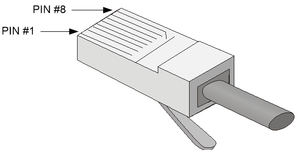
EIA/TIA cabling specifications define two standards, 568A and 568B, for cable pinouts.
· Standard 568A—Pin 1: white/green stripe, pin 2: green steady, pin 3: white/orange stripe, pin 4: blue steady, pin 5: white/blue stripe, pin 6: orange steady, pin 7: white/brown stripe, pin 8: brown steady.
· Standard 568B—Pin 1: white/orange stripe, pin 2: orange steady, pin 3: white/green stripe, pin 4: blue steady, pin 5: white/blue stripe, pin 6: green steady, pin 7: white/brown stripe, pin 8: brown steady.
Ethernet twisted pair cables can be classified into straight-through and crossover cables based on their pinouts
For the pinouts of the twisted pair cables, see the following tables. (A and B represent the two ends of a cable, respectively.)
Table4-1 Straight-through cable pinouts
|
Pinout No. |
A |
B |
|
1 |
Orange/white |
Orange/white |
|
2 |
Orange |
Orange |
|
3 |
Green/white |
Green/white |
|
4 |
Blue |
Blue |
|
5 |
Blue/white |
Blue/white |
|
6 |
Green |
Green |
|
7 |
Brown/white |
Brown/white |
|
8 |
Brown |
Brown |
Table4-2 Crossover cable pinouts
|
Pinout No. |
A |
B |
|
1 |
Orange/white |
Green/white |
|
2 |
Orange |
Green |
|
3 |
Green/white |
Orange/white |
|
4 |
Blue |
Blue |
|
5 |
Blue/white |
Blue/white |
|
6 |
Green |
Orange |
|
7 |
Brown/white |
Brown/white |
|
8 |
Brown |
Brown |
|
|
NOTE: To avoid affecting communication quality, strictly follow the pinouts in the above tables when identifying or making the two types of Ethernet cables. |
Making an Ethernet cable
1. Cut the cable to a required length with the crimping pliers.
2. Strip off an appropriate length of the cable sheath. The length is typically that of the RJ-45 connector.
3. Untwist the pairs so that they can lay flat, and arrange the colored wires based on the wiring specifications.
4. Cut the top of the wires even with one another. Insert the wires into the RJ-45 end and make sure the wires extend to the front of the RJ-45 end and make good contact with the metal contacts in the RJ-45 end and in the correct order.
5. Crimp the RJ-45 connector with the crimping pliers until you hear a click.
6. Use a cable tester to verify the connectivity of the cable.
Connecting an Ethernet cable
1. Plug one end of an Ethernet twisted pair cable into the copper Ethernet port (RJ-45 port) to be connected on the router and the other end of the cable into the Ethernet port of the peer device. The 10/100/1000Base-T copper ports of the router support MDI/MDI-X auto-sensing. They are connected to the network through category-5 or above twisted pairs that are equipped with RJ-45 connectors.
2. Verify the status LED of the Ethernet ports. For more information about the LED status, see H3C SR6616 Routers Hardware Information and Specifications.
Connecting a fiber cable
Transceiver modules
A transceiver module and a fiber cable with an LC or MPO connector are required for connecting a fiber port.
· SFP transceiver modules—Connecting 100/1000 Mbps Ethernet fiber ports and SFP ports on some HIMs.
· XFP transceiver modules—Connecting XFP ports on the HIM-1EXP.
· SFP+ transceiver modules—Connecting GE SFP+ ports on the MCP-X2.
· QSFP+ transceiver modules—Connecting 40GE QSFP+ ports on the MIC-QP1L.
Figure4-4 SFP transceiver module
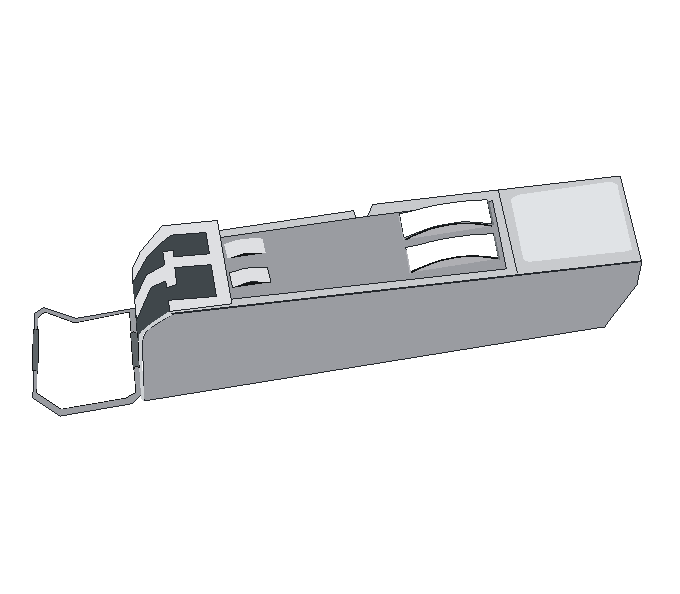
Figure4-5 XFP transceiver module
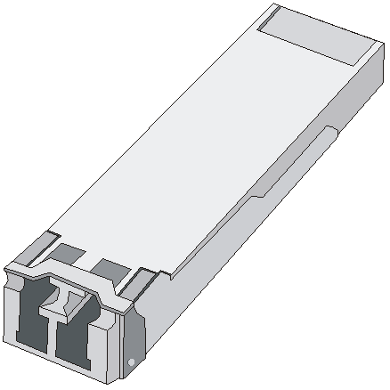
Figure4-6 SFP+ transceiver module
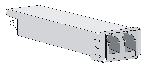
Figure4-7 QSFP+ transceiver module (LC port)
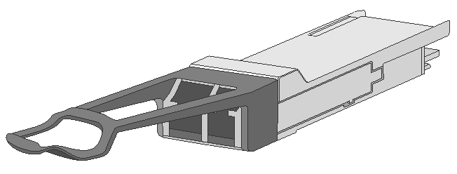
Figure4-8 QSFP+ transceiver module (MPO port)
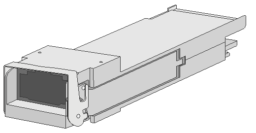
Fiber cables
About fiber cables
You can use an optical fiber to connect a fiber Ethernet port or 10 Gbps Ethernet port. In addition, an optical fiber can connect these types of interface modules: HIM-4GBP/HIM-8GBP, HIM-CL1P/HIM-CL2P, HIM-CLS1P/HIM-CLS2P, HIM-MSP2P/HIM-MSP4P, HIM-PS1P, HIM-AL1P/HIM-AL2P, HIM-RS2P, HIM-1EXP, and MIC-QP1L.
Optical fibers feature low loss and long transmission distance.
Optical fibers can be classified into single-mode fibers and multi-mode fibers. A single-mode fiber carries only a single ray of light; a multi-mode fiber carries multiple modes of lights.
Table4-3 Characteristics of single-mode and multi-mode optical fibers
|
Item |
Single-mode fiber |
Multi-mode fiber |
|
Core |
Small core (10 micrometers or less) |
Larger core than single-mode fiber (50 micrometers, 62.5 micrometers or greater) |
|
Dispersion |
Less dispersion |
Allows greater dispersion and therefore, signal loss exists. |
|
Light source and transmission distance |
Users lasers as the light source often within campus backbones for distance of several thousand meters |
Uses LEDs as the light source often within LANs or distances of a couple hundred meters within a campus network |
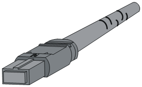
Fiber connectors are indispensable passive components in an optical fiber communication system. They allow the removable connection between optical channels, which makes the optical system debugging and maintenance more convenient. There are multiple types of fiber connectors. Figure4-9 and Figure4-10 shows an LC connector and MPO connector, respectively
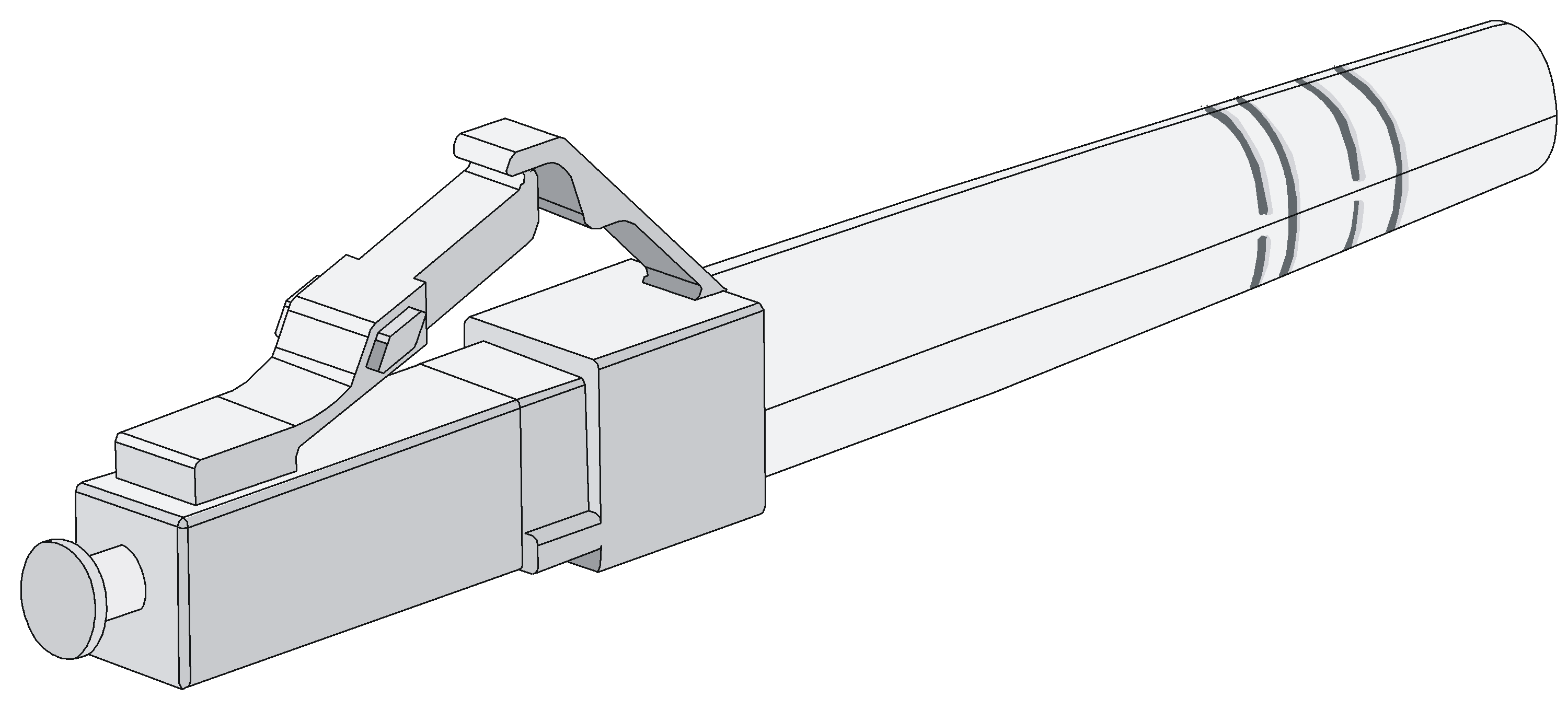
Figure4-10 MPO connector
Restrictions and guidelines
Some cards on the router provide dust plugs for the fiber ports (such as SFP ports). Before using such fiber ports, remove the dust plugs. Keep the dust plugs secure. When the fiber ports are not in use, install the dust plugs.
Fiber connectors are fitted with dust caps. Keep the dust caps secure when the fiber connectors are in use. Install dust caps when the fiber connectors are not in use to avoid damage to their end face. Replace the dust cap if it is loose or polluted.
Before connecting an optical fiber, use dust free paper and absolute alcohol to clean the end face of the two fiber connectors. You can brush the end faces only in one direction.
After a fiber is installed well, the bend radius must be not less than 10 cm (3.94 in).
To pass a fiber through a metallic board hole, make sure the hole has a sleek and fully filleted surface (the filleting radius must be not less than 2 mm, or 0.08 in). To pass a fiber through a metallic board hole or bend it along the acute side of mechanical parts, make sure the fiber wears jackets or cushions.
Insert and remove a plug with care. Never exert a fierce force to the fiber or plug; otherwise the plug might be damaged or the fiber might be broken. Never pull, press or extrude the fiber fiercely. For the allowed maximum tensile load and crush load, see Table4-4.
Table4-4 Allowed maximum tensile force and crush load
|
Period of force |
Tensile load (N) |
Crush load (N/mm) |
|
Short period |
150 |
500 |
|
Long term |
80 |
100 |
Connecting a fiber cable
|
|
WARNING! Do not stare into any fiber port when you connect an optical fiber. The laser light emitted from the fiber port might hurt your eyes. |
Connecting a fiber cable with an LC connector
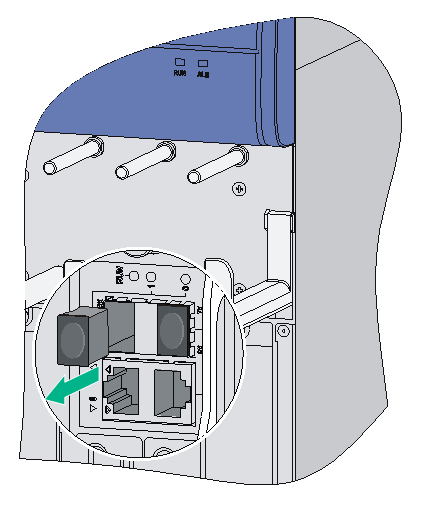
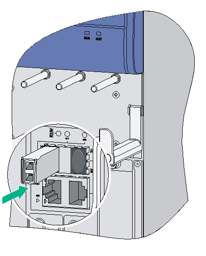
1. Remove the dust plug from a fiber port of the router.
Figure4-11 Removing the dust plug
2. Install the transceiver module.
Figure4-12 Installing the transceiver module
3. Identify the Rx and Tx ports. Plug the LC connector at one end of one fiber cable into the Rx port of the router and the LC connector at the other end into the Tx port of the peer device. Plug the LC connector at one end of another fiber cable into the Tx port of the router and the LC connector at the other end to the Rx port of the peer device.
Figure4-13 Installing the fiber connector
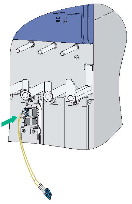
4. View the LINK LED after connection.
¡ If the LED is on, the optical fiber link is present.
¡ If the LED is off, no link is present. This might be because the TX and Rx port of the optical fiber are not connected correctly. In this case, connect the optical fiber again.
Connecting a fiber cable with an MPO connector
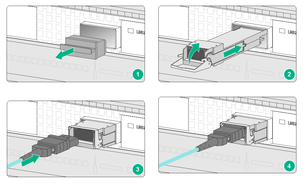
1. Wear an ESD wrist strap. Make sure the wrist strap makes good skin contact and is reliably grounded.
2. Remove the dust plug from the target fiber port.
For interface modules with dust plugs provided as accessories, install dust plugs for empty fiber ports in time.
3. Pull the bail latch on the transceiver module upwards.
4. Take the transceiver module by its two sides and push the end without the bail latch gently into the port until it is firmly seated in the fiber port.
5. Remove the dust plug and dust cap from the transceiver module and fiber connector, respectively.
6. Orient the MPO fiber connector with the white dot on it facing right. Insert the connector horizontally into the transceiver module, and then push it into the transceiver module slightly until it clicks into the place, as shown in Figure4-14.
7. Use cable ties to bind the fiber cable every 150 mm (5.91 in).
8. Attach labels to the fiber cable as required.
Figure4-14 Installing a transceiver module and optical fiber (MPO connector)
Connecting an E1/T1 cable
|
|
CAUTION: When connecting the interface cable, pay attention to the mark on the interface to avoid wrong insertion, which might damage the interface module or even the router. |
As a best practice, install a lightning protector at the input end of the 8T1 cables to protect them against lightning strikes more efficiently when they are led outdoors.
E1/T1 cable overview
E1 cable
You can use an 8E1 interface cable to connect to MIM-8E1(75)/MIM-8E1(75)-F modules.
|
|
NOTE: The coaxial connector and 75-ohm E1 adapter cable are optional accessories, and must be purchased separately if needed. |
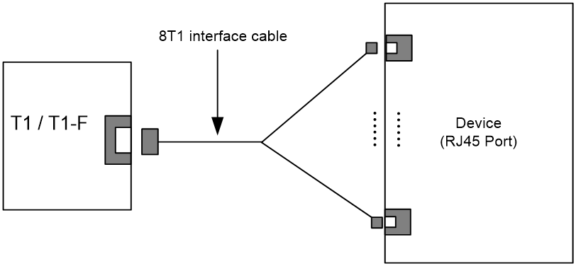
T1 cable
You can use an 8T1 interface cable to connect to MIM-8T1/MIM-8T1-F modules.
Figure4-16 8T1 splitter cable
Connecting an E1/T1 cable
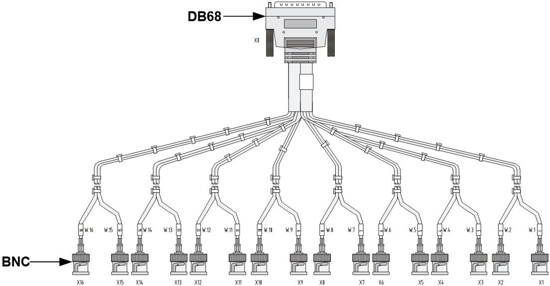
Connecting an E1 cable (D15/D68 <----> BNC)
|
|
CAUTION: When connecting the interface cable, pay attention to the mark on the interface to avoid wrong insertion, which might damage the interface module or even the router. |
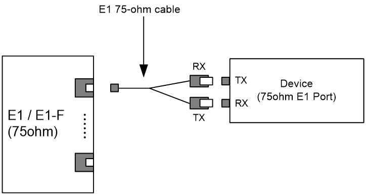
· If you do not need to extend the cable, you can directly connect the BNC connectors of the E1 75-ohm cable to the remote network device as follows.
a. Connect the D15/D68 connector of the E1 75-ohm cable to the D15/D68 interface of the interface module and fasten the bolts to secure the cable.
b. The other end of the cable provides one pair or multiple pairs of 75-ohm BNC connectors. Connect the TX connectors and the RX connectors on this end to the RX connectors and the TX connectors on the remote device respectively.
Figure4-17 Connecting an E1 75-ohm cable
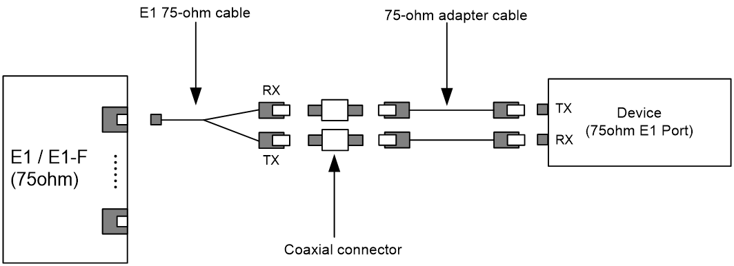
· If you want to extend the cable, connect each BNC connector of the E1 75-ohm cable to one end of a coaxial connector, and connect the remote device to the other end of the coaxial connector through an E1 75-ohm adapter cable.
Figure4-18 Connecting an E1 75-ohm cable
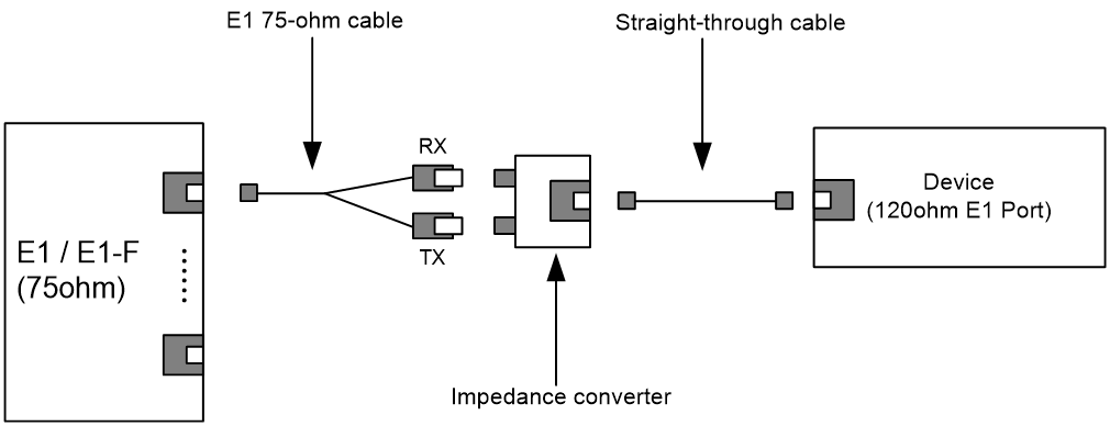
· If the impedance of the E1 interface on the remote device is 120 ohms, you must use an impedance converter to adapt the impedance.
Figure4-19 Connecting an impedance converter
Connecting a T1 cable
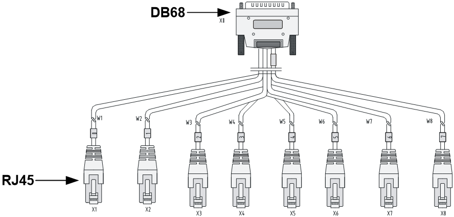
1. Connect the D68 connector of the 8-port T1 cable to the D68 interface on the interface module and fasten the bolts to secure the cable.
2. The other end of the cable provides eight RJ-45 connectors. Connect them to the RJ-45 interface on the remote device as needed.
Figure4-20 Connecting an 8T1 cable
Connecting an E3/T3 cable
As a best practice, install a special lightning protector at the input end of the E3/T3 cables to protect them against lightning strikes more efficiently when they are routed outdoors.
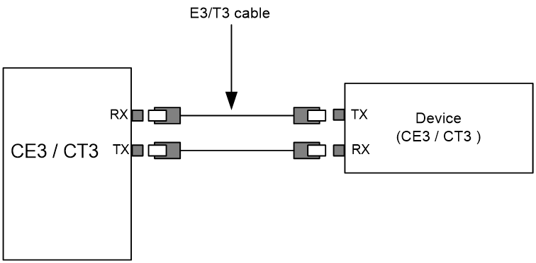
E3/T3 cable overview
You can use an E3/T3 interface cable to connect the MIM-1CE3, MIM-1CT3, and MIM-1T3-V2 modules.

Connecting an E3/T3 cable
1. Connect the SMB connector of an E3/T3 cable to the Tx port on the interface module and the other end to the Rx port on the device to be connected.
2. Connect the SMB connector of another E3/T3 cable to the Rx port of interface module and the other end to the Tx port on the device to be connected
Figure4-22 Connecting an E3/T3 cable
Connecting a serial port cable
Overview
You can use a serial port cable to connect to the MIM-2SAE/MIM-4SAE/MIM-8SAE module. Select a serial port cable according to the link type.
Figure4-23 V.24 DTE cable
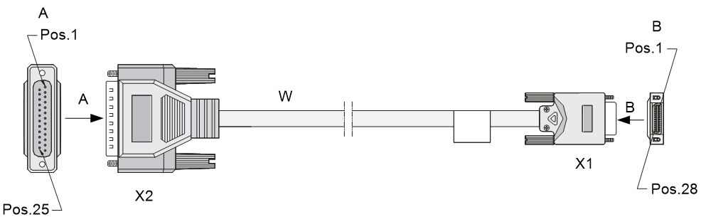
Figure4-24 V.24 DCE cable
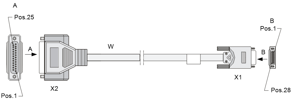
Figure4-25 V.35 DTE cable
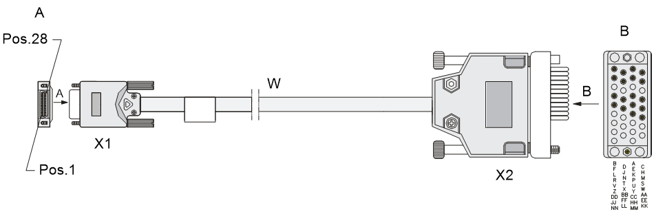
Figure4-26 V.35 DCE cable
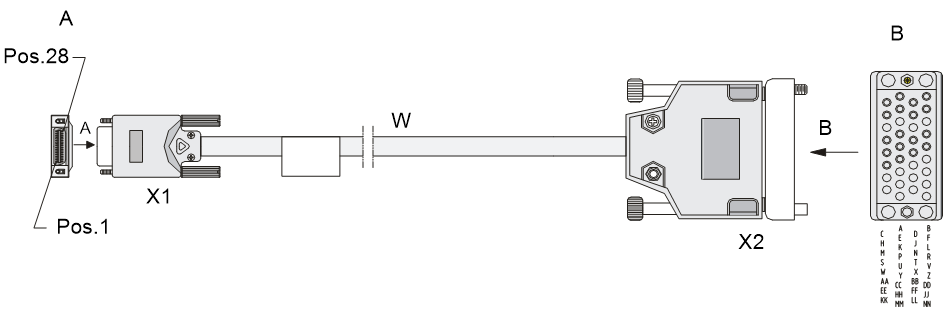
Figure4-27 X.21 DTE cable
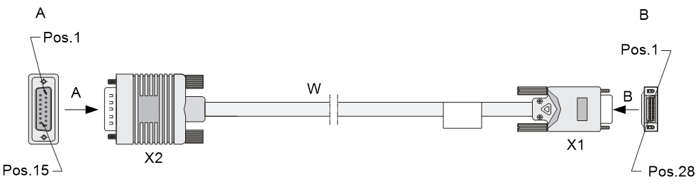
Figure4-28 X.21 DCE cable
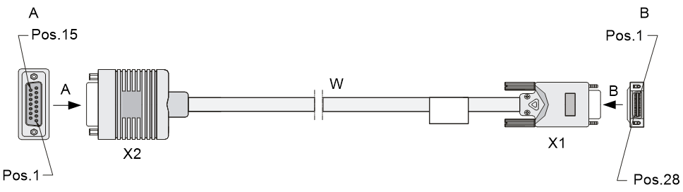
Figure4-29 RS449 DTE cable
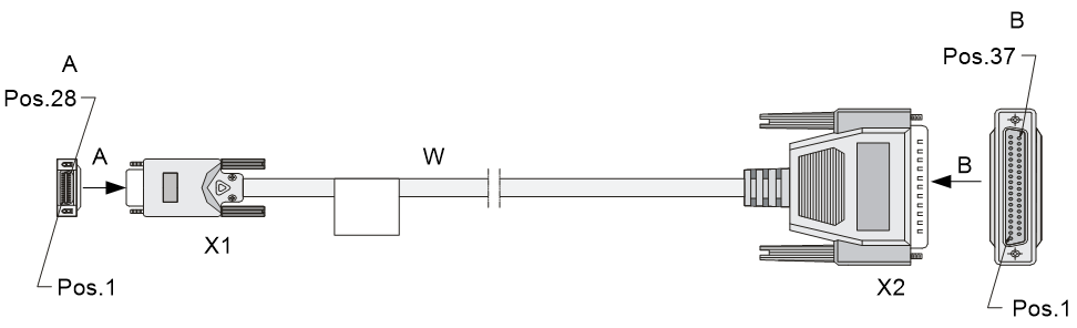
Figure4-30 RS449 DCE cable
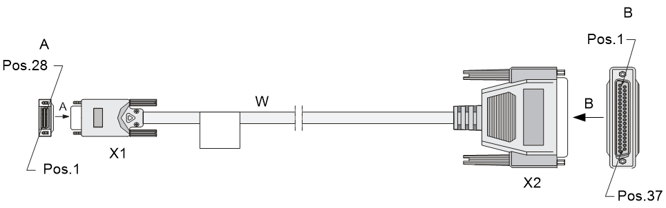
Figure4-31 RS530 DTE cable
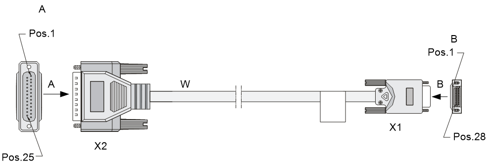
Figure4-32 RS530 DCE cable

Connecting a serial port cable
1. Examine the port type of the peer device and choose the synchronous serial interface cable of correct type.
2. Plug the D28 end of the synchronous serial interface cable into the D28 interface of the SAE interface module.
3. If the WAN uses DDN line, connect the cable to the port of the CSU/DSU.
4. Identify the LINK LED on the SAE panel.
¡ If the LED is on, a link is present.
¡ If the LED is off, a fault has occurred on the link and signal is out of synchronization. In this case, examine the link.
5 Accessing the router
Login methods
The following logins methods are available for you to log in to the router:
· Logging in from the console port, which is the most common way to log in to a router and also the prerequisite for configuring other login methods. You can also use the USB console port to access the router.
· Logging in through Telnet or SSH.
· Logging in from the AUX port.
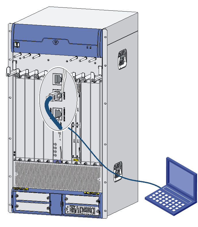
Logging in from the console port/USB console port
You can configure the router by connecting a configuration terminal to the console port or the USB console port on the router.
The first time you access the router, you can only log in to the router from the console port.
Connecting the console port by using a console cable
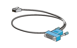
Console cables
As shown in Table5-1, two types of console cables can be used for connecting a configuration terminal to the console port on the router. No console cable is provided with the router. Purchase a console cable as required.
Table5-1 Console cables for connecting the console port
|
Console cable type |
Console cable view |
Router-side connector |
Configuration terminal-side connector |
Connection method |
|
DB9-to-RJ45 console cable |
|
DB-9 female connector |
RJ-45 |
|
|
USB-to-RJ45 console cable |
|
USB |
RJ-45 |
Connecting a DB9-to-RJ45 console cable
|
|
IMPORTANT: The serial ports on PCs do not support hot swapping. To connect a PC to an operating router, first connect the PC end. To disconnect a PC from an operating router, first disconnect the router end. |
To connect the router to a configuration terminal by using a console cable:
1. Select a configuration terminal, which can be a character terminal with an RS-232 serial port, or a PC.
If the PC does not have an RS-232 serial port but a USB port, use a USB to RS-232 adapter for the USB port and install the driver.
2. Plug the DB-9 female connector of the console cable into the serial port on the configuration terminal and the RJ-45 connector into the console port on the router.
Figure5-1 Connecting the console cable
Connecting a USB-to-RJ45 console cable
|
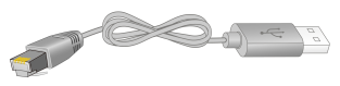
|
IMPORTANT: · To use a USB-to-RJ45 console cable to connect the router to a configuration terminal, first download and install the USB-to-RJ45 console driver on the configuration terminal, and then connect the USB-to-RJ45 console cable to the configuration terminal. To download the USB-to-RJ45 console driver, access the H3C official website or scan the QR code on the cable package. · If you have connected a USB-to-RJ45 console cable to the configuration terminal before installing the driver, remove and reconnect the USB-to-RJ45 console cable to the configuration terminal after driver installation. |
The following installs the driver on the Windows system. To install the driver on other operating systems, see the installation guide in the driver compression package named by using the corresponding operating system.
To connect the router to a configuration terminal by using a USB-to-RJ45 console cable:
1. Click the following link, or copy it to the address bar on your browser and download the USB-to-RJ45 console driver.
http://www.h3c.com/en/home/USB_to_RJ45_Console/
2. View the TXT file Read me in the Windows folder to check whether the Windows system of the configuration terminal supports the driver.
3. If the Windows system supports the driver, install PL23XX-M_LogoDriver_Setup_v200_20190815.exe.
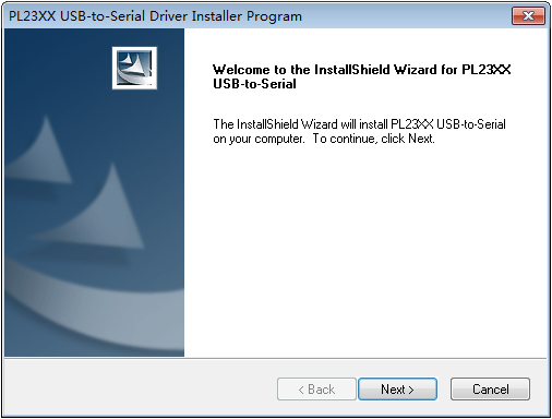
4. Click Next on the welcome page of the driver installation wizard.
Figure5-2 Driver installation wizard
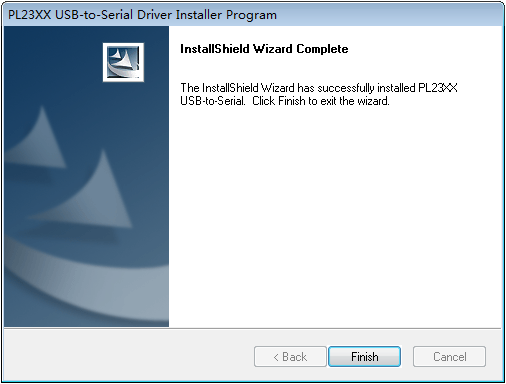
5. Click Finish after the drive installation is completed.
Figure5-3 Finishing the driver installation
6. Connect the standard USB connector of the cable to the USB port of the configuration terminal.
7. Connect the RJ-45 connector of the cable to the console port of the router.
Connecting the USB console port by using a USB cable
|
|
IMPORTANT: After using a USB console cable to connect the router to a configuration terminal, you must download and install the USB console driver program from http://www.h3c.com/ before configuring the device. |
To use a USB console cable to connect the router to a configuration terminal:
1. Click the following link, or copy it to the address bar of the browser to log in to the download page of the USB console driver, and download the driver.
https://www.h3c.com/cn/Home/QR/USBControl.htm
2. Run Installer to pre-install the driver. A message that indicates successful driver pre-installation will pop up when the preinstallation is complete.
3. Connect the standard USB port of the USB cable to the configuration terminal.
4. Connect the mini USB port at the other end of the USB cable to the USB console port on the router. Then, the system will install the driver automatically.
Setting terminal parameters
To access the router from the console port, you must run a terminal emulator program, TeraTermPro or PuTTY, on the configuration terminal. For information about using a terminal emulator program, see the program's user guide.
The following are the required terminal settings:
· Baud rate—9600.
· Data bits—8.
· Stop bits—1.
· Parity—none.
· Flow control—none.
Powering on the router
Checking before power-on
Before powering on the router, verify the following items:
· The power cord and grounding cable are correctly connected.
· The power source voltage meets the requirement of the router.
· The console cable is correctly connected; the terminal or PC used for configuration has started, and the configuration parameters have been set.
· If a CF card is used, verify that the CF card is in position.
Checking after power-on
After powering on the router, check the following items:
· The LEDs on the front panel of the MPU are normal. For the LED description, see H3C SR6616 Routers Hardware Information and Specifications.
· The fans operate correctly, and you can hear fan rotating.
· The configuration terminal displays information normally. You can see the startup window on the local configuration terminal. For more information, see "Displaying boot information."
· After the power-on self-test (POST), the system prompts you to press Enter. When the command line prompt appears, the router is ready to configure.
Displaying boot information
After power-on, the router initializes its memory, and then runs the extended BootWare. The following information appears on the terminal screen:
System start booting...
Press Ctrl+D to access BASIC-BOOTWARE MENU
Press Ctrl+T to start memory test
Booting Normal Extend BootWare....
****************************************************************************
* *
* H3C SR66 BootWare, Version 7.1.064 *
* *
****************************************************************************
Copyright (c) 2004-2017 New H3C Technologies Co., Ltd.
Compiled Date : Apr 6 2017
CPU Type : MPC8548E
CPU L1 Cache : 32KB
CPU Clock Speed : 1000MHz
Memory Type : DDR2 SDRAM
Memory Size : 1024MB
Memory Speed : 400MHz
BootWare Size : 1024KB
Flash Size : 4MB
cfa0 Size : 495MB
NVRAM Size : 128KB
BASIC CPLD Version : 134.0
EXTEND CPLD Version : 133.0
PCB Version : Ver.C
BootWare Validating...
Press Ctrl+B to enter extended boot menu...
|
|
NOTE: · If the router is configured with two RPE-X1 MPUs in both slot 4 and slot 5, the router boots by using the RPE-X1 MPU in slot 4 by default. · If the router is configured with two RSE-X1 MPUs in both slot 5 and slot 6, the router boots by using the RSE-X1 MPU in slot 5 by default. |
Starting to get the main application file--cfa0:/main.bin!..................
......................................................
The main application file is self-decompressing
..........................................................................
..........................................................................
.......
.......
Done!
System is starting.....
Starting application at 0x00010000 ...
Mainboard 0 is master.
User interface con0 is available.
Press ENTER to get started.
Press Enter, and the following prompt appears:
<H3C>
You can now configure the router.
Logging in to the router through Telnet
1. After powering on the router, log in to the router through the console port. Enable the Telnet function on the router and set user privileges.
2. Connect the PC to the management Ethernet interface on the router and specify an IP address for the interface.
3. Specify an IP address for the PC, make sure the PC and the interface are in the same network segment.
For more information about how to log in to the router through Telnet, see H3C SR6600/SR6600-X Routers Configuration Guides.
Configuring basic settings
|
Step |
Command |
Remarks |
|
1. Set the current time and date. |
clock datetime time date |
Optional. Available in user view. |
|
1. Enter system view. |
system-view |
Required. Available in user view. |
|
2. Enter Ethernet interface view. |
interface interface-type interface-number |
N/A |
|
3. Specify an IP address for the interface. |
ip address ip-address { mask-length | mask } [ sub ] |
By default, no IP address is assigned to any interface. |
|
4. Return to system view. |
quit |
Available in any view. |
|
5. Specify a static route. |
ip route-static dest-address { mask | mask-length } { next-hop-address | interface-type interface-number [ next-hop-address ] | vpn-instance d-vpn-instance-name next-hop-address } track track-entry-number [ preference preference-value ] [ tag tag-value ] [ description description-text ] |
Required. By default, the preference of a static route is 60, tag is 0, and no description is configured. Do not specify the permanent keyword together with the bfd or track keyword. |
|
6. Save the current configuration to the root directory of the storage media, and specify it as the boot file to be used at the next boot. |
save [ safely ] [ backup | main ] [ force ] |
Available in any view. |
|
7. Display the running configuration. |
display current-configuration |
Available in any view. |
6 Replacement procedures
The router uses a modular, all-pluggable design, and supports replacing hot swappable modules without interrupting the router operation.
Safety recommendations
1. Always wear an ESD wrist strap or ESD gloves when replacing the modules.
2. When working with a removable module, such as an MPU, RPE-X1/RPE-X3/RPE-X5/RPE-X5E carrier (used when you use an RPE-X1/RPE-X3/RPE-X5/RPE-X5E MPU), FIP module, SAP module, switching fabric module, memory module, CF card, or HIM/MIM/MIC, follow these guidelines:
¡ Ensure good alignment with the slot to avoid damage to the module during installation or removal.
¡ Before removing a module, make sure the captive screws are completely loosened. Otherwise, the panel of the module might be deformed.
¡ Avoid touching any components on the PCB during observing or moving the module.
¡ Put the removed module on an antistatic workbench with the PCB side facing upward or place them in antistatic bags.
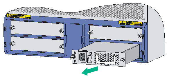
Replacing a power supply
The replacement procedure of an AC power supply is the same as a DC power supply. This section takes an AC power supply as an example.
To replace a power supply:
1. Loosen the captive screws of the power supply to be removed until all spring pressure is released.
2. Gently pull the power supply out of the slot along the slide rails.
Figure6-1 Pulling out the power supply
3. Put the removed power supply on an antistatic workbench or into an antistatic bag.
4. If you do not install a new power supply in the slot, install a filler panel. To install a power supply, see "Installing a power supply."
Replacing an MPU
Prerequisites
|
|
IMPORTANT: When a module is in unstable state, do not use the reboot command to trigger an active/standby switchover. You can use the display system stable state command to display the system stability and status information. |
1. If the router is configured with only one MPU, make sure all power sources to the router are turned off before replacing the MPU.
2. If the router is configured with two MPUs, make sure both MPUs operate correctly before replacing any MPU.
¡ As a best practice to replace the active MPU, execute the reboot command in the system view of the active MPU to trigger an active and standby switchover. For more information about the reboot command, see the command reference manual.
¡ To replace the standby MPU, you can remove it immediately.
Replacing an RPE-X1/RPE-X3/RPE-X5/RPE-X5E MPU
The replacement procedures for the RPE-X1, RPE-X3, RPE-X5, and RPE-X5E MPUs are the same. This example uses an RPE-X1.
To replace an RPE-X1 MPU:
1. Determine the MPU to be removed. This section takes the MPU in slot 4 as an example.
2. Loosen the captive screws of the MPU to be removed until all spring pressure is released.
3. Holding the ejector levers of the MPU with both hands, pull the ejector levers outward, and gently pull the MPU out of the slot along the slide rails.
Figure6-2 Pulling the RPE-X1 MPU out of the slot
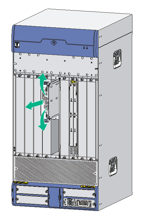
4. Install a new RPE-X1 MPU. For more information, see "Installing an RPE-X1/RPE-X3/RPE-X5/RPE-X5E MPU."
Replacing an RSE-X1 MPU
1. Determine the MPU to be removed. This section takes the MPU in slot 5 as an example.
2. Loosen the captive screws of the MPU to be removed until all spring pressure is released.
3. Holding the ejector levers of the MPU with both hands, pull the ejector levers outward, and gently pull the MPU out of the slot along the slide rails.
Figure6-3 Pulling the RSE-X1 MPU out of the slot
4. If you do not install a new MPU in the slot, install a filler panel. To install a new MPU, see "Installing an RSE-X1 MPU."
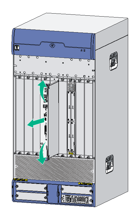
Replacing an MCP
To replace an MCP, for example, MCP-X1:
1. Determine the MCP to be removed. This section takes the MCP in slot 5 as an example.
2. Loosen the captive screws on the MCP to be removed until all spring pressure is released.
3. Holding the ejector levers of the MCP with both hands, pull the ejector levers outward, and gently pull the MCP out of the slot along the slide rails.
Figure6-4 Pulling the MCP out of the slot
4. If you do not install a new MCP in the slot, install a filler panel. To install a new MCP, see "Installing an MCP MPU."
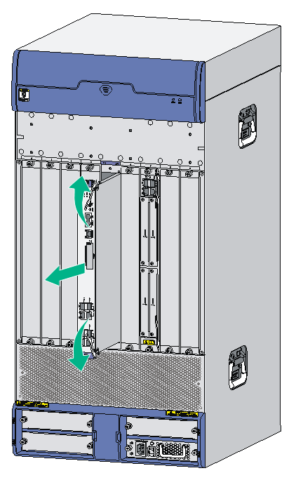
Replacing a FIP module
1. Determine the FIP module to be removed. This section takes the FIP module in slot 7 as an example.
2. Loosen the captive screws of the FIP module to be removed until all spring pressure is released.
3. Holding the ejector levers of the FIP module with both hands, pull the ejector levers outward, and gently pull the FIP module out of the slot along the slide rails.
Figure6-5 Pulling the FIP module out of the slot

4. If you do not install a new FIP module in the slot, install a filler panel. To install a new FIP module, see "Installing a FIP module."
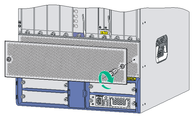
Replacing an SSD drive
Before you remove an SSD drive, remove the service module from the router. For the removal procedure of service modules, see "Replacing a FIP module" or "Replacing a SAP/OAP/switching fabric module."
To remove an SSD drive:
1. Use a Phillips screwdriver to remove the fastening screws on the SSD drive.
2. Gently lift the SSD drive free from the connector and slightly pull the SSD drive out of the slot.
Keep the SSD drive secure.
3. Install a new SSD drive. For the installation procedure, see "Installing an SSD drive."
Figure6-6 Removing an SSD drive
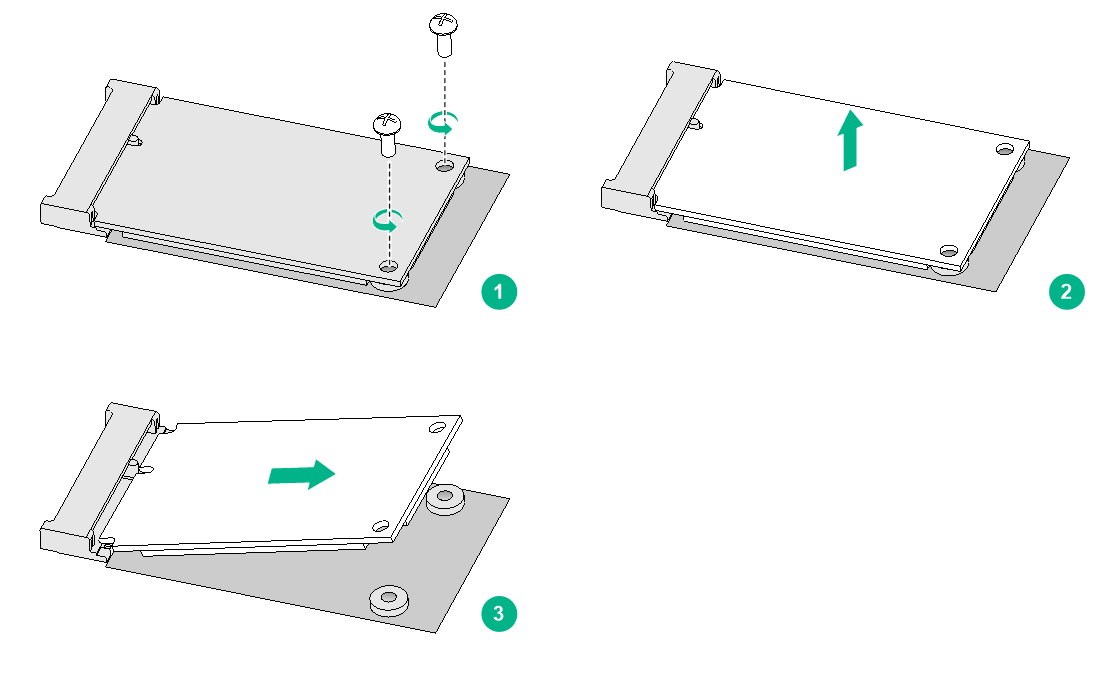
Replacing a SAP/OAP/switching fabric module
|
|
CAUTION: To avoid hardware damage, do not hot swap a SAP/OAP/switching fabric module when its RUN LED is fast flashing. |
To replace a SAP/OAP/switching fabric module:
1. Determine the SAP/OAP/switching fabric module to be removed. This section takes the SAP module in slot 7 as an example.
2. Loosen the captive screws of the SAP module to be removed until all spring pressure is released.
3. Holding the ejector levers of the SAP module with both hands, pull the ejector levers outward, and gently pull the SAP module out of the slot along the slide rails.
Figure6-7 Pulling the SAP module out of the slot
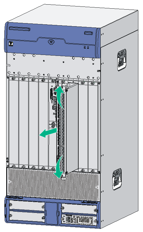
4. If you do not install a new SAP module in the slot, install a filler panel. To install a new SAP module, see "Installing a SAP/OAP/switching fabric module."
Replacing a HIM/MIM/MIC/MIC-X
|
|
CAUTION: To avoid hardware damage, do not hot swap a HIM/MIM/MIC/MIC-X interface module on a FIP when the RUN LED of the FIP module is fast flashing. |
|
|
IMPORTANT: After you remove a HIM/MIM/MIC/MIC-X from a FIP, the HIM/MIM/MIC/MIC-X settings will not automatically restore if you reinstall the HIM/MIM/MIC/MIC-X on the FIP after the FIP reboots. To save the settings, make sure the HIM/MIM/MIC is in position before rebooting the FIP module or inserting the FIP module into the router. |
|
|
IMPORTANT: A MIC-X-ET16-compatible FIP module supports only one MIC-X-ET16 assembled by a MIC-X adapter module and a MIC-ET16L interface module. |
The replacement procedure is similar for HIMs, MIMs, MICs, and MIC-Xs.
To replace a HIM/MIM/MIC/MIC-X:
1. Loosen the captive screws of the HIM/MIM/MIC/MIC-X to be removed.
2. Fully open the ejector levers on the HIM/MIM/MIC/MIC-X. Hold the ejector levers and then gently pull the HIM/MIM/MIC/MIC-X out of the slot along the slide rails.
The ejector levers of the FIP module are long. When removing the HIM/MIM/MIC/MIC-X in slot 1 on the FIP module, avoid touching the right ejector lever of the FIP module.
Figure6-8 Removing a HIM/MIM/MIC/MIC-X

3. If you are not to install a new HIM/MIM/MIC/MIC-X in the slot, install a filler panel. To install a new HIM/MIM/MIC/MIC-X, see "Installing a HIM/MIM/MIC/MIC-X interface module."
Replacing a CF card
|
|
CAUTION: To avoid hardware damage, do not remove the CF card when the router is booting or the CF LED is flashing. |
1. Make sure the CF card LED is not flashing. A flashing CF card LED means that the system is accessing the CF card.
To replace the CF card on the MCP, remove the CF card cover first.
2. As shown in Figure6-9, press the CF card eject button of the CF card reader so that the eject button protects from the panel.
Figure6-9 Pressing the eject button
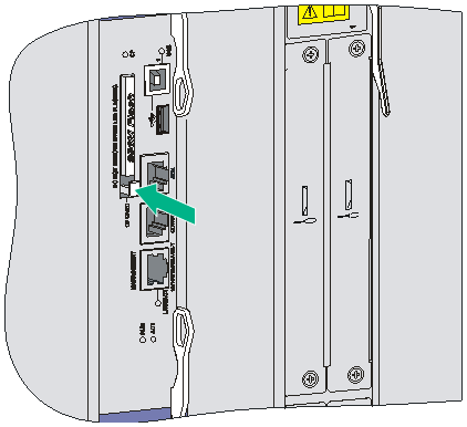
3. Press the eject button again to eject the CF card part-way out of the CF card reader, and then pull the CF card out of the CF card reader.
Figure6-10 Pressing the eject button to eject the CF card
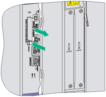
4. Install a new CF card. For more information, see "Installing a CF card."
|
|
NOTE: To protect the CF card, place it into an antistatic bag. |
Replacing a transceiver module
|
|
WARNING! · Do not stare into the optical fibers. · When removing a transceiver module, do not touch the golden finger of the transceiver module. |
1. Remove the optical fibers from the transceiver module.
2. Pivot the clasp down to the horizontal position.
3. As shown in Figure6-11, holding the handle of the transceiver module, gently pull the transceiver module out.
4. Insert the plastic plug to the removed transceiver module, and put the transceiver module into its original shipping materials.
5. If you do not install a new transceiver module in the interface, install a dust-proof plug in the interface. To install a transceiver module, see "Connecting a fiber cable."
Figure6-11 Removing a transceiver module
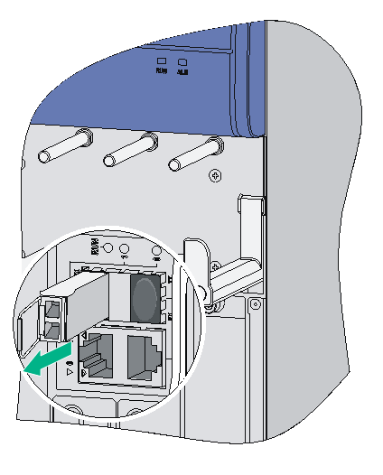
Replacing a fan tray
|
|
CAUTION: · The router supports automatic fan speed adjustment and hot-swapping of the fan tray. · Keep your hands away from the spinning fan blades when removing the fan tray. |
To replace a fan tray:
1. Loosen the captive screws of the fan tray to be removed until all spring pressure is released.
2. Gently pull the fan tray out of the slot along the slide rails.
Figure6-12 Pulling out the fan tray
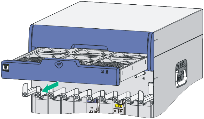
3. Install a new fan tray. For more information, see "Installing a fan tray."
|
|
NOTE: · Do not keep the router working without a fan tray for more than two minutes because poor ventilation might result in damage to the router. · To protect the removed fan tray, place it in an antistatic bag. · For more information about the LED status on the fan tray, see H3C SR6616 Routers Hardware Information and Specifications. |
Replacing an air filter
|
|
CAUTION: You can clean the air filter with water, but wait until it is completely dry before installing it again. |
An air filter is an optional accessory.
To replace an air filter:
1. Loosen the captive screws of the air filter to be removed until all spring pressure is released.
Figure6-13 Removing the air filter
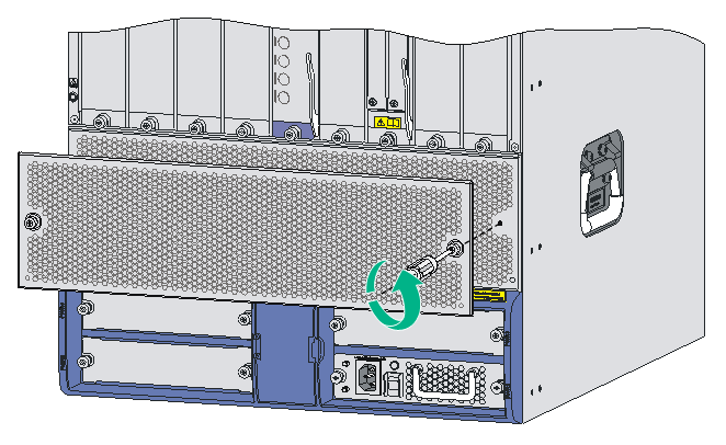
2. Install a new air filter. For more information, see "Installing an air filter."
Replacing a memory module
The RPE-X1s and FIPs are equipped with memory modules. Before installing or removing a memory module, remove the RPE-X1 or FIP from the chassis first. For more information, see "Replacing an MPU," "Replacing an RSE-X1 MPU," and "Replacing a FIP module."
When to replace a memory module
|
|
CAUTION: Use the memory modules provided by H3C only. Otherwise, the router might be unable to operate correctly. |
For the memory module specifications, see H3C SR6616 Routers Hardware Information and Specifications. Memory modules are removable components of the router.
You need to replace a memory module in the following situations:
· More memory is needed to upgrade the application program.
· The router needs to maintain a large routing table or support other highly memory consuming operations.
· An existing memory module is damaged.
Figure6-14 Memory module replacement flowchart
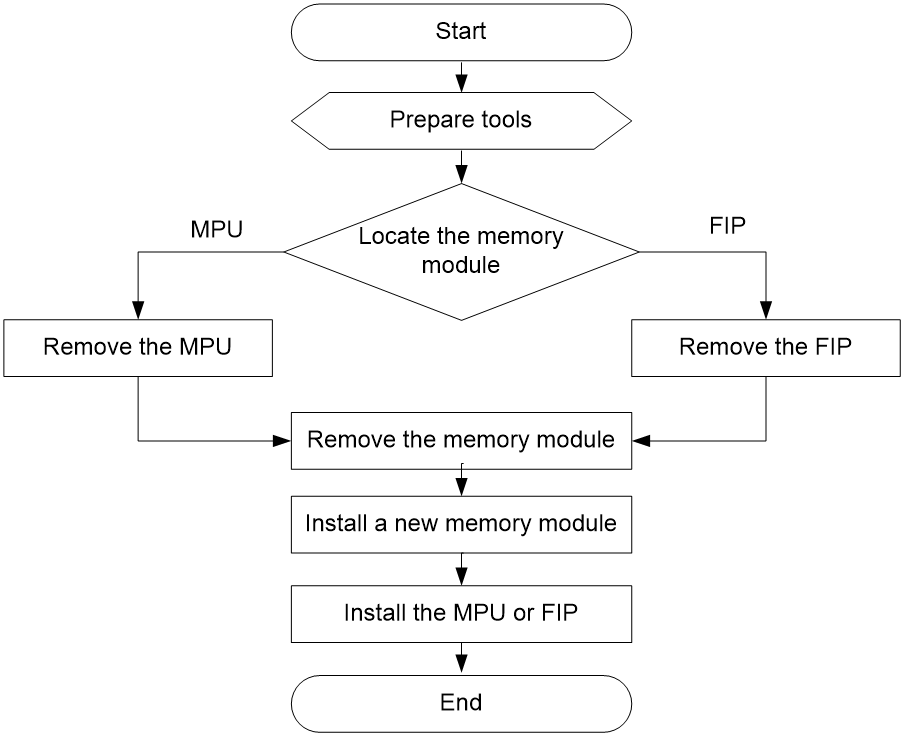
Memory module structure
Figure6-15 Memory module structure (DDR2)
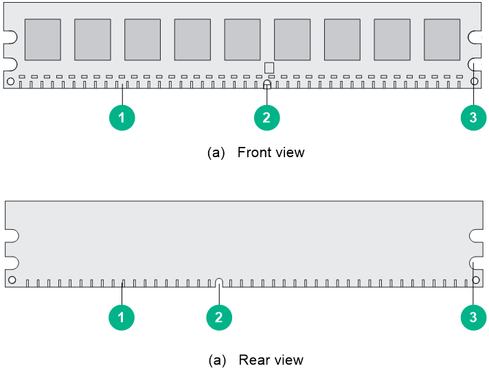
|
(1) Connector edge |
(2) Polarization notch |
(3) Latch notch |
Figure6-16 Memory module structure (DDR3)
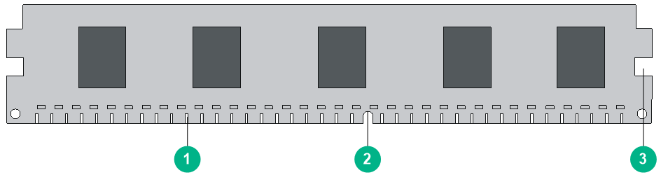
|
(1) Connector edge |
(2) Polarization notch |
(3) Latch notch |
Memory module slot
Figure6-17 Memory module slot
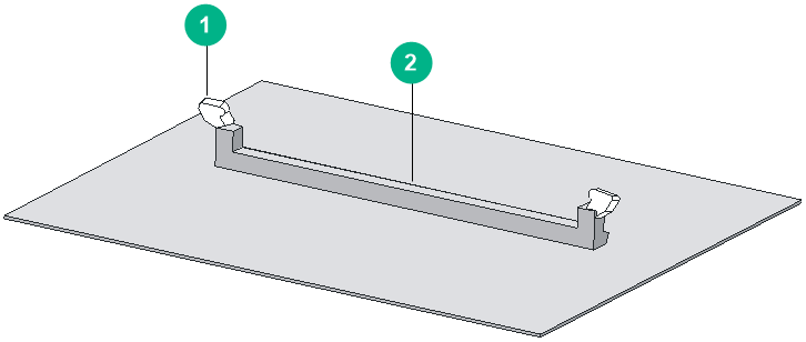
|
(1) Release latch |
(2) Memory module slot |
Replacing a memory module
|
|
CAUTION: · Do not touch the surface-mounted components of the memory module directly with your hands to avoid damaging the memory module. Hold the memory module only at its non-conductive edge. · To protect the removed memory module, place it in an antistatic bag. |
To replace a memory module:
1. Determine the module (MPU or FIP) for which you will replace a memory module, and put the module on a flat workbench.
2. Pull the release latches away from the memory module at both ends so that the memory module is lifted from the memory module slot.
3. Holding the non-conductive edge, remove the memory module.
Figure6-18 Removing the memory module
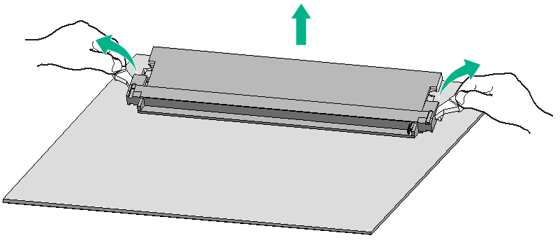
4. Align the polarization notch of the memory module with the key in the connector.
5. Insert the memory module into the slot.
6. Carefully and firmly press the memory module at both ends until you hear a click. This indicates the memory module is seated in the memory module slot.
7. Verify that the release latches have firmly locked the memory module in position.
Figure6-19 Installing the memory module
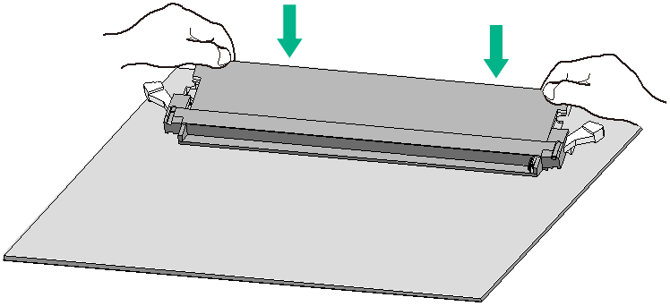
7 Hardware management and maintenance
The output depends on your router model. For more information about the commands used in this chapter, see H3C SR6600/SR6600-X Routers Command References.
Displaying hardware information for the router
Displaying the software and hardware version information for the router
Use the display version command to display software and hardware version information of the router. The output includes the following information: the current software version and hardware version, router operating time, type, and operating time of each main processing unit (MPU) and service module. The output of this command depends on your router model.
<Sysname> display version
Displaying the operational statistics for the router
When you perform routine maintenance or the system fails, you might need to view the operational information of each functional module for locating failures. Generally, you need to run display commands one by one. To collect more information one time, you can execute the display diagnostic-information command in any view to display or save the operational statistics of multiple functional modules of the router. This command displays the output of the display clock, display version, display device, and display current-configuration commands.
· To save the operational statistics of each functional module of the router, type y when the system prompts you to save or display the diagnostic information.
<Sysname> display diagnostic-information
Save or display diagnostic information (Y=save, N=display)? [Y/N]:y
Please input the file name(*.diag)[cfa0:/default.diag]:aa.diag
Diagnostic information is outputting to cfa0:/aa.diag.
Please wait...
Save succeeded.
Execute the more aa.diag command in user view, and then press the Page Up and Page Down keys to view the contents of the file aa.diag.
· To display the operational statistics of each functional module of the router, type n when the system prompts you to save or display the diagnostic information. The output is too much and omitted here.
<Sysname> display diagnostic-information
Save or display diagnostic information (Y=save, N=display)? [Y/N]:n
=================================================
===============display clock===============
=================================================
08:54:16 UTC Fri 11/12/2017
===================================================
===============display version===============
===================================================
…Omitted…
Displaying detailed information about a module
Use the display device verbose command to display detailed information of modules in each slot.
<Sysname>display device verbose
System-mode(Current/After Reboot): Normal/Normal
Slot No. Board type Status Primary SubSlots
---------------------------------------------------------------------
0 N/A Absent N/A N/A
1 N/A Absent N/A N/A
2 N/A Absent N/A N/A
3 N/A Absent N/A N/A
4 RPE-X1 Normal Master 0
5 N/A Absent N/A N/A
6 N/A Absent N/A N/A
7 FIP-210 Startup N/A 2
8 N/A Absent N/A N/A
9 N/A Absent N/A N/A
Use the display device slot slot-number command to display detailed information about the module in the specified slot.
<Sysname> display device slot 4
System-mode(Current/After Reboot): Normal/Normal
Slot 4 : RPE-X1
SubSlot No. Card Type Status Max Ports
--------------------------------------------------------
0 Fixed SubCard Normal 3
Table7-1 Command output
|
Field |
Description |
|
Slot No. |
Slot number of the module |
|
Card Type |
Module model. The value NONE indicates that no module is present in the slot. |
|
Status |
Running status of the module: · Absent—No module is present in the slot. · Fault—The module in the slot is booting, or the module fails and cannot boot correctly. · Normal—The module in the slot is a service module and is operating correctly. |
|
Max Ports |
Maximum number of submodules that that module supports. |
Displaying the electrical label information for a module
Use the display device manuinfo command to display the electrical label information of the module in each slot.
Electrical label information is also called permanent configuration data or archive information, which includes the module name, serial number, MAC address, and vendor name.
<Sysname> display device manuinfo
Slot 4:
DEVICE_NAME:NONE
DEVICE_SERIAL_NUMBER:NONE
MAC_ADDRESS:NONE
MANUFACTURING_DATE:NONE
VENDOR_NAME:H3C
Slot 7:
DEVICE_NAME:NONE
DEVICE_SERIAL_NUMBER:NONE
MAC_ADDRESS:NONE
MANUFACTURING_DATE:NONE
VENDOR_NAME:H3C
Use the display device manuinfo slot slot-number command to display the electrical label information of the module in the specified slot.
<Sysname> display device manuinfo slot 7
Slot 7:
DEVICE_NAME:NONE
DEVICE_SERIAL_NUMBER:NONE
MAC_ADDRESS:NONE
MANUFACTURING_DATE:NONE
VENDOR_NAME:H3C
Table7-2 Command output
|
Field |
Description |
|
DEVICE_NAME |
Module type |
|
DEVICE_SERIAL_NUMBER |
Module serial number |
|
MAC_ADDRESS |
MAC address of the module: · An MPU has a MAC address. · A service module does not have a MAC address, and the field is displayed as NONE. |
|
MANUFACTURING_DATE |
Manufacturing data of the module |
|
VENDOR_NAME |
Vendor name |
|
The operation is not supported on the specified board or subslot |
The display device manuinfo command is not supported on a module that is virtualized through the MPU. |
Displaying the CPU usage of a module
Use the display cpu-usage command to display the CPU usage of the module in each slot.
<Sysname> display cpu-usage
Slot 4 CPU usage:
2% in last 5 seconds
2% in last 1 minute
1% in last 5 minutes
Table7-3 Command output
|
Field |
Description |
|
Slot 4 CPU usage |
CPU usage of the module in slot 4. If the module in the slot has multiple CPUs, Slot 4 CPU usage shows the usage of the main CPU of the module in slot 4, and Slot 4 CPU 1 CPU usage shows the usage of the standby CPU of the module in slot 4. |
|
1% in last 5 seconds |
Average CPU usage in the last five seconds (after the router boots, the router calculates and records the average usage at the interval of five seconds). |
|
1% in last 1 minute |
Average CPU usage in the last minute (after the router boots, the router calculates and records the average usage at the interval of one minute). |
|
1% in last 5 minutes |
Average CPU usage in the last five minutes (after the router boots, the router calculates and records the average usage at the interval of five minutes). |
Displaying the memory usage of a module
Use the display memory command to display the memory information of the MPU.
<Sysname> display memory
System Total Memory(bytes): 431869088
Total Used Memory(bytes): 71963156
Used Rate: 16%
|
Field |
Description |
|
System Total Memory(bytes) |
Physical memory size (in bytes) of the module |
|
Total Used Memory(bytes) |
Used memory size (in bytes) of the module |
|
Used Rate |
Memory usage of the module |
Displaying the CF card information
Use the display device cf-card command to display the CF card information.
<Sysname> display device cf-card
Slot No. Dev No. Status Size(M)
-----------------------------------------------
0 0 Normal 495
0 1 Absent N/A
Table7-5 Command output
|
Field |
Description |
|
Slot No |
Slot number of the CF card |
|
Dev No. |
Device number of the CF card: · 0 for a built-in CF card · 1 for an external CF card |
|
Status: |
Operational status of the CF card: · Absent—No CF card is present in the slot. · Fault—The CF card has failed. · Normal—The CF card is operating correctly. |
|
Size: |
Storage capacity of the CF card |
Displaying the operational status of the fan
Use the display fan command to display the operational status of the fan.
<Sysname> display fan
Fan 1 State: Normal
Table7-6 Command output
|
Field |
Description |
|
Fan 1 |
Number of the fan |
|
State |
The fan state: · Normal—The fan is operating correctly. · Absent—The fan is not in position. · Fault—The fan has failed. |
Displaying the operational status of power supplies
Use the display power-supply command to display the operational status of power supplies.
<Sysname> display power-supply
Power No. State Description
------------------------------------------------
1 Absent Unknown
2 Normal VAPEL-300AC
Table7-7 Command output
|
Field |
Description |
|
Power No. |
Power supply slot |
|
State |
Power supply state: · Normal—The power supply is operating correctly. · Absent—The power supply is not in position. · Fault—The power supply has failed. |
|
Description |
Description for the power supply |
Displaying the alarming thresholds of a module
When the router is operating, too high a temperature and too low a temperature of a module affect the normal operation of the router. When the temperature of a module exceeds 80°C (176°F) or drops below 0°C (32°F), the system sends traps to prompt you to solve the problem.
To display the alarming thresholds of a module:
|
Step |
Command |
Remarks |
|
1. Enter system view. |
system-view |
N/A |
|
2. Display the temperature information of your router. |
display environment |
Optional Available in any view |
Port configuration and management
Configuring a combo interface
Combo interface overview
A combo interface is a logical interface comprising an SFP port of a transceiver module and an RJ-45 Ethernet port. The two ports share one forwarding interface, so they cannot work simultaneously. When you enable either port, the other port is automatically disabled. You can select to activate a port as needed.
Configuration prerequisites
Use the display interface interface-type interface-number command to find out which port is an SFP port and which port is an RJ-45 Ethernet port.
· If the output includes "Media type is not sure, Port hardware type is No connector", it means that the port is an SFP port. For example, the following output shows that GigabitEthernet 2/0/1 is an SFP port.
[Sysname] display interface GigabitEthernet 2/0/1
GigabitEthernet2/0/1 current state: DOWN
IP Packet Frame Type: PKTFMT_ETHNT_2, Hardware Address: 0000-fc00-7506
Description: GigabitEthernet2/0/1 Interface
Loopback is not set
Media type is not sure,Port hardware type is No connector
Unknown-speed mode, unknown-duplex mode
Link speed type is autonegotiation, link duplex type is autonegotiation
· If the output includes "Media type is twisted pair, Port hardware type is 1000_BASE_T", it means that the interface is an RJ-45 Ethernet port. For example, the following output shows that GigabitEthernet 2/0/0 is an RJ-45 Ethernet port.
[Sysname] display interface GigabitEthernet 2/0/0
GigabitEthernet2/0/0 current state: DOWN ( Administratively )
IP Packet Frame Type: PKTFMT_ETHNT_2, Hardware Address: 0000-fc00-7506
Description: GigabitEthernet 2/0/0 Interface
Loopback is not set
Media type is twisted pair
Port hardware type is 1000_BASE_T
Unknown-speed mode, unknown-duplex mode
Link speed type is autonegotiation, link duplex type is autonegotiation
Configuring a combo interface
|
Step |
Command |
Remarks |
|
1. Enter system view. |
system-view |
N/A |
|
2. Enter view of the SFP port or RJ-45 port of the combo interface. |
interface interface-type interface-number |
N/A |
|
3. Activate the RJ-45 Ethernet port or SFP port. |
combo enable { copper | fiber } |
Required. By default, the Ethernet port is active. |
Displaying transceiver module information and alarming information
Introduction to transceiver modules
Table7-8 Commonly used transceiver modules
|
Transceiver module type |
Application scenarios |
Whether can be an optical transceiver |
Whether can be an electrical transceiver |
|
SFP (Small Form-factor Pluggable) |
Typically used for 100M/1000M Ethernet ports or POS 155M/622M/2.5G ports |
Yes |
Yes |
|
XFP(10-Gigabit small Form-factor Pluggable) |
Typically used for 10G ports |
Yes |
No |
|
SFP+ |
Typically used for 10G ports |
Yes |
No |
|
QSFP+ |
Typically used for 40G ports |
Yes |
No |
Displaying transceiver module information
To identify transceiver modules, you can use the following command to view the key parameters of the transceiver modules, including transceiver module type, connector type, central wavelength of the laser sent, transmission distance, and vendor name or name of the vendor who customizes the transceiver modules.
To display transceiver module information:
|
Task |
Command |
Remarks |
|
Display key parameters of the transceiver module in a specified interface. |
display transceiver interface [ interface-type interface-number ] |
Available for all transceiver modules |
Displaying the alarming information or fault detection parameters for a transceiver module
The system outputs alarm information for you to locate and troubleshoot faults of transceiver modules. For the H3C-customized transceiver modules, the system can also monitor the key parameters, such as temperature, voltage, laser bias current, TX power, and RX power. When these parameters are abnormal, you can take corresponding measures to prevent transceiver module faults.
Perform the following operation to display the alarming information or fault detection parameters of a transceiver module:
|
Task |
Command |
Remarks |
|
Display the current alarm information of the transceiver module in a specified interface. |
display transceiver alarm interface [ interface-type interface-number ] |
Available for all transceiver modules |
|
|
NOTE: For more information about the transceiver module displaying commands, see H3C SR6600/SR6600-X Routers Command References. |
Saving the current configuration of the router
You can save the current configuration of the router in one of the following methods:
· Fast saving—Executing the save command without the safely keyword. This mode saves the file more quickly but is likely to lose the existing configuration file if the router reboots or the power fails during the process. The fast saving mode is suitable for environments where the power supply is stable.
· Safe saving—Executing the save command with the safely keyword. The mode saves the file more slowly but can retain the configuration file in the router even if the router reboots or the power fails during the process. The safe saving mode is preferred in environments where a stable power supply is unavailable or remote maintenance is involved.
To save the current configuration of the router:
|
Task |
Command |
Remarks |
|
Save the current configuration to the specified file, but the configuration file will not be set as the file for the next startup. |
save file-url [ all | slot slot-number ] |
Use either command Available in any view |
|
Save the current configuration to the root directory of the storage medium of the active or standby MPU and specify the file as the startup configuration file that will be used at the next system startup. |
save [ safely ] |
|
|
NOTE: · The configuration file must be with extension .cfg. · During the execution of the save command, the startup configuration file to be used at the next system startup might be lost if the router reboots or the power supply fails. In this case, the router will boot with the factory defaults, and after the router reboots, you need to re-specify a startup configuration file for the next system startup. |
Rebooting a module or router
When upgrading and maintaining the startup configuration file or configuration file for the router, you need to reboot the router. After you change the operating mode of a MPU or service module, you must restart the corresponding module. To reboot a router, use one of the following methods:
· Use the reboot command to reboot a router.
· Enable the scheduled reboot function at the CLI. You can set a time at which the router can automatically reboot, or set a delay so that the router can automatically reboot within the delay.
· Power on the router after powering it off, which is also called hard reboot or cold start. Powering off a running router causes data loss and hardware damages, and therefore is not recommended.
If you execute the reboot command without specifying the slot keyword, the command reboots the router, including the active MPU, standby MPU, the switching fabric modules, and the service modules.
If the main startup configuration file does not exist, do not use the reboot command to reboot the router or the active MPU. In this case, you should specify the main startup configuration file first, and then reboot the active MPU.
The precision of the rebooting timer is 1 minute. One minute before the rebooting time, the router prompts "REBOOT IN ONE MINUTE" and reboots in one minute.
If you are performing file operations when the router is to be rebooted, the system does not execute the reboot command for security.
To reboot the router immediately:
|
Task |
Command |
Remarks |
|
Reboot the router or the module in the specified slot immediately. |
reboot [ slot slot-number ] |
Required Available in user view |
To enable the scheduled reboot function:
|
Task |
Command |
Remarks |
|
Enable the scheduled reboot function and specify a specific reboot time and date. |
schedule reboot at hh:mm [ date ] |
Use either command The scheduled reboot function is disabled by default. Available in user view |
|
Enable the scheduled reboot function and specify a reboot waiting time. |
schedule reboot delay { hh:mm | mm } |
8 Troubleshooting
|
|
IMPORTANT: The barcode stuck on the router chassis contains production and servicing information. Before you return a faulty router for serving, provide the barcode information of the router to H3C Support. |
MPU failures
RUN LED is off
Symptom
The RUN LED of the MPU is off. For more information about the RUN LED, see H3C SR6616 Routers Hardware Information and Specifications.
Solution
To resolve the issue:
1. Verify that the MPU is installed in a right slot.
¡ An RPE-X1/RPE-X3/RPE-X5/RPE-X5E MPU must be installed in slot 4 or slot 5.
¡ An RSE-X1 MPU must be installed in slot 5 or slot 6.
¡ An MCP-X1/X2 must be installed in slot 5 or slot 6.
2. Verify that the router is powered on correctly. A green POWER LED indicates that the router is powered on correctly.
3. If the issue persists, contact H3C Support.
RUN LED fast flashes
Symptom
Five minutes after the router is powered on or the MPU is inserted in the router, if the RUN LED of the MPU still fast flashes at 8 Hz.
To troubleshoot the MPU failure:
1. Verify that the terminal display is correct.
2. Verify that the software image file properties are correct in the BootWare menu.
3. If the issue persists, contact H3C Support.
ALM LED is steady on or flashes
Symptom
The ALM LED of the MPU is steady on or flashes.
Solution
To resolve the issue:
1. View the output on the serial terminal and the software management tool. For example:
¡ The system displays the following information when it is in high temperature:
%Jun 25 14:38:45:444 2017 H3C DRVMSG/3/TempCritical:
CPU temperature critical in Slot 3, index is 1.
¡ The system displays the following information when it cannot provide enough power.
%Apr 26 12:07:42:320 2017 H3C DRVMSG/1/InSufficientPwr:
No sufficient power, failed to power on slot 3.
¡ The system displays the following information when a redundant power supply fails.
%Apr 26 16:16:49:518 2017 H3C DRVMSG/1/REDUNDANT POWER-SUPPLY FAILURE:
Redundant power-supply failed, left 0 unit(s).
2. Resolve the issue based on the output.
3. If the issue persists, contact H3C support.
FIP module failures
RUN LED is off
Symptom
The RUN LED on the FIP module is off.
Solution
To resolve the issue:
1. Verify that the router is powered on.
2. Verify that the FIP module is installed in a right slot.
3. Verify that the system provides enough power. If the power is not enough, the system displays the following information:
%Apr 26 16:46:32:169 2017 H3C DRVMSG/1/InSufficientPwr:
No sufficient power, failed to power on slot 3.
4. If the issue persists, contact H3C Support..
RUN LED fast flashes
Symptom
20 minutes after the router is powered on or the FIP module is installed in the router, the RUN LED on the FIP module still fast flashes at 8 Hz.
Solution
To resolve the issue, contact H3C Support.
Power supply failures
Power LED is off
Symptom
The router cannot be powered on and the power LED on the front panel is off.
Solution
To resolve the issue:
1. Verify that the power switch is turned on.
2. Verify that the power cables of the router are firmly connected.
3. Verify that the switch of the power source is turned on.
4. Verify that the power cable is not damaged.
5. If the issue persists, contact H3C Support.
Red power LED is on
Symptom
The router cannot be powered on and the red power LED on the front panel is on.
Solution
To resolve the issue:
1. Verify that the power switch is turned on and the power supply is firmly seated.
2. Verify that the power source meets the requirements of the router.
3. If the issue persists, contact H3C Support.
Fan failures
Fan tray is absent
Symptom
After the router is booted, the system displays the following information:
%Jul 5 14:47:20:618 2017 H3C DEV/4/FAN ABSENT:
Fan 1 is absent.
Solution
To resolve the issue:
1. Verify that the fan tray is in position.
2. Verify that the fan tray is in firm contact with the backplane of the router chassis.
3. If the issue persists, contact H3C Support.
ALM LED is red
Symptom
When the router is running, the ALM LED on the fan tray panel might turn red, and the following information might appear on the configuration terminal:
%Jul 5 14:59:03:878 2017 H3C DRVMSG/3/FanPlugIn:Fan 1 Plug In.
%Jul 5 14:59:03:879 2017 H3C DRVMSG/3/FanErr:Fan 1 Error.
#Jul 5 14:59:03:998 2017 H3C DEV/1/FAN STATE CHANGES TO FAILURE:
Trap 1.3.6.1.4.1.2011.2.23.1.12.1.6<fanfailure>: fan ID is 1
%Jul 5 14:59:03:998 2017 H3C DEV/4/FAN FAILED:
Fan 1 failed.
Solution
To resolve the issue:
1. Identify whether any foreign object has entered the fan tray.
2. If the issue persists, contact H3C Support.
HIM/MIM/MIC/MIC-X failures
Symptom
When a HIM/MIM/MIC/MIC-X is plugged while the router is running, the following information might appear on the configuration terminal:
%Apr 26 15:36:09:404 2017 H3C DRVICOUT/1/DrvIcOutStr:Slot=5;(Src Slot[5])
Slot 5/2 Plug In Failed!
Solution
To resolve the issue:
1. Verify that the HIM/MIM/MIC/MIC-X is installed securely.
2. Verify that the HIM/MIM/MIC/MIC-X is installed correctly in a FIP module. For HIM/MIM/MIC/MIC-X and FIP module compatibility, see H3C SR6600/SR6600-X Routers Interface Module Guide.
3. Verify that the interface module connector pins of the FIP module are bent.
4. If the issue persists, contact H3C Support.
Configuration system issues
If the configuration environment setup is correct, the configuration terminal displays boot information when the router is powered on. If the setup is incorrect, the configuration terminal displays nothing or garbled text.
No terminal display
Symptom
The configuration terminal displays nothing when the router is powered on.
Solution
To resolve the issue:
1. Verify that the power supply system is operating correctly and the console cable is correctly connected.
2. Verify that the console cable is connected to a correct serial port.
3. Verify that the following terminal settings are correct:
¡ Bits per second—9600.
¡ Data bits—8.
¡ Parity—None.
¡ Stop bits—1.
¡ Flow control—None.
¡ Terminal emulation—VT100.
4. If the issue persists, contact H3C Support.
Garbled terminal display
Symptom
Terminal display is garbled.
Solution
To resolve the issue:
1. Make sure the Data bits field is set to 8 for the console terminal. If the Data bits field is set to 5 or 6, the console terminal will display garbled characters.
2. Make sure the Bits per second field is set to 9600 kbps. An incorrect bits per second might also cause the configuration terminal to display garbled characters.
3. If the issue persists, contact H3C Support.
No response from the serial port
Symptom
The serial port gives no response.
Solution
To resolve the issue:
1. Verify that the serial port settings are correct. For more information about the serial port settings, see "Setting terminal parameters."
2. If the issue persists, contact H3C Support.
Dealing with console login password loss
|
|
CAUTION: Dealing with console login password loss from BootWare menus requires device reboot and is service-disruptive. |
How to deal with console login password loss depends on the state of password recovery capability (see Figure8-1). Password recovery capability controls console user access to the device configuration and SDRAM from BootWare menus.
· If password recovery capability is enabled, a console user can access the device configuration without authentication and configure new passwords.
· If password recovery capability is disabled, a console user must restore the factory-default configuration before configuring new passwords. Restoring the factory-default configuration deletes the main and backup next-startup configuration files.
To enhance system security, disable password recovery capability.
Figure8-1 Dealing with console login password loss
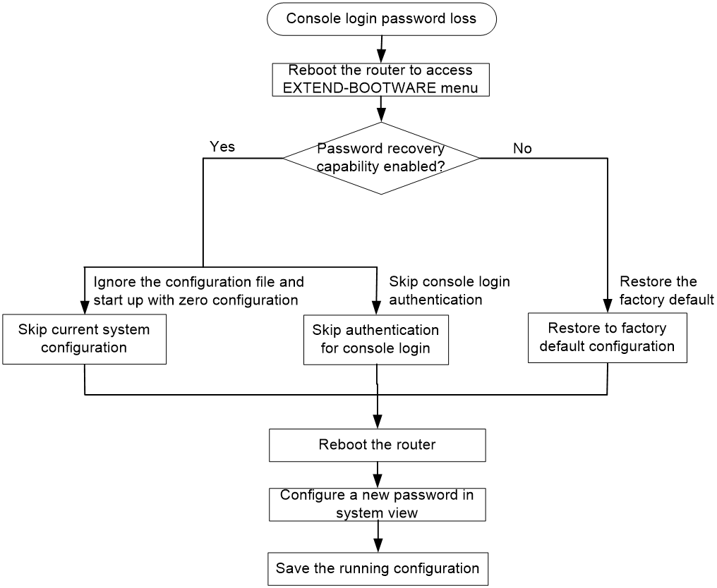
Examining the state of password recovery capability
1. Reboot the router.
System is starting...
Press Ctrl+D to access BASIC-BOOTWARE MENU
Press Ctrl+T to start memory test
Booting Normal Extend BootWare........
****************************************************************************
* *
* H3C SR66 BootWare, Version 7.1.064 *
* *
****************************************************************************
Copyright (c) 2004-2017 New H3C Technologies Co., Ltd.
Compiled Date : Apr 6 2017
CPU Type : MPC8548E
CPU L1 Cache : 32KB
CPU Clock Speed : 1000MHz
Memory Type : DDR2 SDRAM
Memory Size : 1024MB
Memory Speed : 400MHz
BootWare Size : 1024KB
Flash Size : 4MB
cfa0 Size : 495MB
NVRAM Size : 128KB
BASIC CPLD Version : 134.0
EXTEND CPLD Version : 133.0
PCB Version : Ver.C
BootWare Validating...
Press Ctrl+B to enter extended boot menu...
2. Press Ctrl + B within three seconds after the "Press Ctrl+B to enter extended boot menu..." prompt message appears.
BootWare password: Not required. Please press Enter to continue.
3. Press Enter and read the password recovery capability state message displayed before the EXTEND-BOOTWARE menu.
Password recovery capability is enabled.
Note: The current operating device is cfa0
Enter < Storage Device Operation > to select device.
==========================<EXTENDED-BOOTWARE MENU>==========================
|<1> Boot System |
|<2> Enter Serial SubMenu |
|<3> Enter Ethernet SubMenu |
|<4> File Control |
|<5> Restore to Factory Default Configuration |
|<6> Skip Current System Configuration |
|<7> BootWare Operation Menu |
|<8> Skip Authentication for Console Login |
|<9> Storage Device Operation |
|<0> Reboot |
============================================================================
Ctrl+Z: Access EXTENDED ASSISTANT MENU
Ctrl+F: Format File System
Ctrl+C: Display Copyright
Enter your choice(0-9):
Skipping current system configuration
1. Reboot the router to access the EXTEND-BOOTWARE menu, and then enter 6.
Password recovery capability is enabled.
Note: The current operating device is cfa0
Enter < Storage Device Operation > to select device.
==========================<EXTENDED-BOOTWARE MENU>==========================
|<1> Boot System |
|<2> Enter Serial SubMenu |
|<3> Enter Ethernet SubMenu |
|<4> File Control |
|<5> Restore to Factory Default Configuration |
|<6> Skip Current System Configuration |
|<7> BootWare Operation Menu |
|<8> Skip Authentication for Console Login |
|<9> Storage Device Operation |
|<0> Reboot |
============================================================================
Ctrl+Z: Access EXTENDED ASSISTANT MENU
Ctrl+F: Format File System
Ctrl+C: Display Copyright
Enter your choice(0-9): 6
After the configuration skipping flag is set successfully, the following message appears:
Flag Set Success.
2. When the EXTEND-BOOTWARE menu appears again, enter 0 to reboot the router.
The router starts up with empty configuration.
3. To use the configuration in the next-startup configuration file, load the file in system view.
<sysname> system-view
[sysname] configuration replace file startup.cfg
Current configuration will be lost, save current configuration? [Y/N]:n
Info: Now replacing the current configuration. Please wait...
Info: Succeeded in replacing current configuration with the file startup.cfg.
4. Configure a new console login password.
In the following example, the console login authentication mode is password and the authentication password is 123456. For security, the password is always saved in hashed format to the configuration file, regardless of whether you specify the simple keyword or hash keyword for the set authentication password command.
<sysname> system-view
[sysname] user-interface console 0
[sysname-ui-console0] authentication-mode password
[sysname-ui-console0] set authentication password simple 123456
5. To make the settings take effect after a reboot, save the running configuration to the next-startup configuration file.
[sysname] save
Skipping authentication for console login
1. Reboot the router to access the EXTEND-BOOTWARE menu, and then enter 8.
Password recovery capability is enabled.
Note: The current operating device is cfa0
Enter < Storage Device Operation > to select device.
==========================<EXTENDED-BOOTWARE MENU>==========================
|<1> Boot System |
|<2> Enter Serial SubMenu |
|<3> Enter Ethernet SubMenu |
|<4> File Control |
|<5> Restore to Factory Default Configuration |
|<6> Skip Current System Configuration |
|<7> BootWare Operation Menu |
|<8> Skip Authentication for Console Login |
|<9> Storage Device Operation |
|<0> Reboot |
============================================================================
Ctrl+Z: Access EXTENDED ASSISTANT MENU
Ctrl+F: Format File System
Ctrl+C: Display Copyright
Enter your choice(0-9): 8
The router deletes the console login password configuration commands from the main next-startup configuration file. After the operation is completed, the following message appears:
Clear Image Password Success!
2. When the EXTEND-BOOTWARE menu appears again, enter 0 to reboot the router.
3. Configure a new password for console login (see "Configure a new console login password.").
4. To make the setting take effect after a reboot, save the running configuration to the next-startup configuration file.
[sysname] save
Restoring to factory default configuration
1. Reboot the router to access the EXTEND-BOOTWARE menu, and enter 5.
Password recovery capability is disabled.
Note: The current operating device is cfa0
Enter < Storage Device Operation > to select device.
==========================<EXTENDED-BOOTWARE MENU>==========================
|<1> Boot System |
|<2> Enter Serial SubMenu |
|<3> Enter Ethernet SubMenu |
|<4> File Control |
|<5> Restore to Factory Default Configuration |
|<6> Skip Current System Configuration |
|<7> BootWare Operation Menu |
|<8> Skip Authentication for Console Login |
|<9> Storage Device Operation |
|<0> Reboot |
============================================================================
Ctrl+Z: Access EXTENDED ASSISTANT MENU
Ctrl+F: Format File System
Ctrl+C: Display Copyright
Enter your choice(0-9): 5
2. At the prompt for confirmation, enter Y.
The router deletes its main and backup next-startup configuration files and restores the factory-default configuration.
The current mode is no password recovery. The configuration files will be
deleted, and the system will start up with factory defaults, Are you sure to
continue?[Y/N]Y
Setting...Done.
3. When the EXTEND-BOOTWARE menu appears again, enter 0 to reboot the router.
The router starts up with the factory-default configuration.
4. Configure a new console login password (see "Configure a new console login password.").
5. To make the settings take effect after a reboot, save the running configuration to the next-startup configuration file.
[sysname] save
Cooling system failure
Symptom
When the environmental temperature of a module reaches or exceeds the high temperature threshold, the fans rotate at full speed, and the following information appears on the configuration terminal:
%Might 4 19:37:29:945 2017 H3C DRVMSG/3/Temp2High:
Environment temperature too high in Slot 5, index is 0.
When the CPU temperature of a module reaches or exceeds the high temperature threshold, the fans rotate at full speed, and the following information appears on the configuration terminal:
%Might 4 19:37:29:945 2017 H3C DRVMSG/3/Temp2High:
CPU temperature too high in Slot 5, index is 0.
When the environmental temperature of a module reaches or exceeds the critical temperature threshold, the fans rotate at full speed, and the following information appears on the configuration terminal repeatedly:
%Might 4 19:37:54:945 2017 H3C DRVMSG/3/TempCritical:
Environment temperature critical in Slot 5, index is 0.
When the CPU temperature of a module reaches or exceeds the critical temperature threshold, the fans rotate at full speed, and the following information appears on the configuration terminal repeatedly:
%Might 4 19:37:54:945 2017 H3C DRVMSG/3/TempCritical:
CPU temperature critical in Slot 5, index is 0.
When the environmental or CPU temperature of a module exceeds the critical temperature threshold, the ALM LED of the MPU is red.
Solution
To resolve the issue:
1. Verify that the fans are running correctly.
2. Verify that the operating environment of the router is well ventilated.
3. Use the display environment command to identify whether the temperature in the router keeps rising.
For more information about the display environment command, see H3C SR6600/SR6600-X Routers Fundamentals Command Reference.
4. If the temperature inside the router exceeds 90°C (194°F), power off the router immediately and contact H3C Support.
Ethernet port failure
Symptom
Unshielded twisted pairs connect Ethernet ports and one or both ends of the link supports 100Base-TX. One end operates at 100 Mbps and the other end operates at 10 Mbps. The following failures occur:
· No link is present for the end operating at 100 Mbps.
· A link is present for the end operating at 10 Mbps, but the physical layer LED (for example, the Active LED) keeps flashing, and the port cannot transmit or receive traffic correctly.
Solution
To resolve the issue:
1. Change the rate and duplex mode of a port by force to make sure the rate and duplex mode of the local end are the same as the peer end.
For the copper FE ports and GE ports, both the rate and duplex mode are auto-negotiated by default.
2. If the issue persists, contact H3C Support.
Interface module, cable, and connection failure
Symptom
After a HIM/MIM/MIC/MIC-X is installed and the router is powered on, the LEDs on the HIM/MIM/MIC/MIC-X panel might indicate abnormal operation.
Solution
To resolve the issue:
1. Verify that the HIM/MIM/MIC/MIC-X cable is correctly selected.
2. Verify that the HIM/MIM/MIC/MIC-X cable is correctly connected.
3. Use the display command to identify whether the interface on the interface module has been correctly configured and is operating correctly.
4. If the issue persists, contact H3C Support.
Software upgrade failures
No response from the serial port of the MPU
Symptom
The serial port of the MPU gives no response.
Solution
To resolve the issue:
1. Verify that the serial port settings are correct (whether the Bits per second field is set to 9600 kbps).
2. If the issue persists, contact H3C Support.
For more information about the serial port settings, see "Setting terminal parameters."
TFTP upgrade failure
Symptom
Start the router, and upgrade the software through TFTP. The following issues might occur:
· The CF card has no enough space.
File will be transferred in binary mode
Downloading file from remote TFTP server, please wait...\
Failed to write data into storage device, maybe no enough space on device
· The file to be downloaded is not found.
File will be transferred in binary mode
Downloading file from remote TFTP server, please wait...
File not found.
· The configuration of the network port is incorrect.
Can't connect to the remote host
Solution
To resolve the issue:
1. Delete some files in the CF card or use a new CF card so that enough space is available for the system software image.
2. Type the correct file name.
3. Configure the network port correctly, and make sure the network port is up and you can successfully ping the TFTP server from the network port.
4. If the issue persists, contact H3C Support.
FTP upgrade failure
Symptom
Start the router, and upgrade the software through FTP. The following issues might occur:
· The CF card has no enough space.
227 Entering Passive Mode (192,168,1,10,10,204)
150 "xxx" file ready to send (xxx bytes) in ASCII mode
FTP: Error Writing Local File(Screen).
· The file to be downloaded is not found.
227 Entering Passive Mode (192,168,1,10,10,203)
550 Error: File xxx does not exist
FTP: Error Writing Local File(Screen).
· The configuration of the network port is incorrect.
FTP: Unrecognized host or wrong IP address!
Solution
To resolve the issue:
1. Delete some files in the CF card or use a new CF card so that enough space is available for the system software image.
2. Type the correct file name.
3. Configure the network port correctly, and make sure the network port is up and you can successfully ping the FTP server from the network port.
4. If the issue persists, contact H3C Support.
System software image file missing errors
Symptom
When none of the main, backup, and secure system software image files exists, the system displays the following information at startup:
BootWare Validating...
Application program does not exist.
Please input BootWare password:
If you select 1 on the main BootWare menu, the system displays the following information:
Starting to get the main application file--cfa0:/main.bin!
The main application file does not exist--cfa0:/main.bin!
Starting to get the backup application file--cfa0:/backup.bin!
The backup application file does not exist--cfa0:/backup.bin!
Starting to get the secure application file--cfa0:/secure.bin!
The secure application file does not exist--cfa0:/secure.bin!
Booting App fails!
The name of the main, backup, and secure system software image files vary by user settings.
Solution
To solve this issue:
1. Download the software image again or set the file properties in the BootWare file list.
2. If the issue persists, contact H3C Support.
