- Released At: 24-12-2024
- Page Views:
- Downloads:
- Table of Contents
- Related Documents
-
|
|
|
H3C Intelligent Management Center |
|
Deployment Guide |
|
|
New H3C Technologies Co., Ltd.
http://www.h3c.com
Document version: 5W100-20241218
Software version: IMC PLAT 7.3 (E0710)
Copyright © 2024 New H3C Technologies Co., Ltd. All rights reserved.
No part of this manual may be reproduced or transmitted in any form or by any means without prior written consent of New H3C Technologies Co., Ltd.
Except for the trademarks of New H3C Technologies Co., Ltd., any trademarks that may be mentioned in this document are the property of their respective owners.
The information in this document is subject to change without notice.
Preface
This deployment guide primarily covers the installation and deployment of H3C Intelligent Management Center (IMC), including its installation, upgrade, access, and uninstallation.
This preface includes the following topics about the documentation:
· Audience.
· Conventions.
Audience
This documentation is intended for:
· Network planners.
· Field technical support and servicing engineers.
· Network administrators working with H3C IMC.
Conventions
The following information describes the conventions used in the documentation.
GUI conventions
|
Convention |
Description |
|
Boldface |
Window names, button names, field names, and menu items are in Boldface. For example, the New User window opens; click OK. |
|
> |
Multi-level menus are separated by angle brackets. For example, File > Create > Folder. |
Symbols
|
Convention |
Description |
|
|
An alert that calls attention to important information that if not understood or followed can result in data loss, data corruption, or damage to hardware or software. |
|
|
An alert that calls attention to essential information. |
|
NOTE: |
An alert that contains additional or supplementary information. |
Documentation feedback
You can e-mail your comments about product documentation to [email protected].
We appreciate your comments.
Contents
Restrictions for using the embedded database
Deployment restrictions and guidelines
Obtaining IMC installation and deployment methods
Hardware requirements of the IMC platform
Hardware requirements of the EIA component
Hardware requirements of the WSM component
Installation requirements of the embedded database
Preparing the installation environment
Uninstalling previous versions of IMC
Checking the database configuration
(Optional.) Checking the installation environment
Installing and deploying the IMC platform
Selecting the installation type
Installing the IMC platform in typical mode
Installing the IMC platform in custom mode
Deploying the IMC platform component
Deploying IMC on a member server (distributed deployment)
Starting the remote installation wizard
Installing the Intelligent Deployment Monitoring Agent
Deploying the IMC platform subcomponents
Managing IMC by using the Intelligent Deployment Monitoring Agent
Starting the Intelligent Deployment Monitoring Agent
Installing and deploying IMC service components
Installing and deploying IMC BIMS
Deploying IMC BIMS on the conductor server
Deploying BIMS subcomponents on a member server
Installing and deploying IMC UAM
Deploying UAM subcomponents on the conductor server
Deploying UAM subcomponents on a member server
Installing and deploying IMC MVM
Installing a DHCP plug-in on an MS DHCP server
Installing a DHCP plug-in on a Linux DHCP server
Installing an LLDP Windows agent
Installing an LLDP Linux agent
Hardware, software, and browser requirements
Accessing the UAM self-service center
Accessing IMC from a mobile device
Uninstalling all IMC components at one time
Uninstalling IMC components from each member server
Uninstalling IMC components from the conductor server
Backing up and restoring the database
Starting DBMan on the database server (for remote databases only)
Installing DBMan on the database server
Backing up and restoring databases for a single IMC system
Backing up and restoring databases in stateless failover scenarios
Backing up and restoring databases
Configuration restrictions and guidelines
Overview
The following information describes the IMC deployment schemes.
· Centralized deployment
¡ Local database—This deployment scheme scales to networks from 50 to 500 devices.
¡ Remote database—This deployment scheme scales to networks from 200 to 10000 devices.
¡ Embedded database—This deployment scheme scales to small networks.
· Distributed deployment
¡ Local database—This deployment scheme scales to networks from 200 to 15000 devices.
¡ Remote database—This deployment scheme scales to networks of 500 to 150000 devices.
IMC components
IMC includes the IMC platform and service components.
IMC platform
The IMC platform is the base component to provide IMC services and includes the following subcomponents:
· Resource Management
· Alarm Management
· User Self Service Management
· Guest Access Management
· Intelligent Configuration Center
· Report Management
· Network Element (NE) Management
· Performance Management
· ACL Management
· Network Asset Management
· Security Control Center
· General Search Service Management
· Syslog Management
· VLAN Management
· WeChat Server
Service components
Service components are optional and purchased separately from the IMC platform. The IMC platform is the basis for implementing various services and must be installed before service component deployment.
IMC includes the following service components:
· Endpoint Intelligent Access (EIA)—Includes User Access Manager (UAM) and TACACS+ Authentication Manager (TAM).
¡ User Access Manager (UAM)—Provides policy-based Authentication, Authorization and Accounting (AAA) services. UAM software extends management to wired, wireless and remote network users and enables the integration of network device, user, guest and terminal management on a single unified platform.
¡ TACACS+ Authentication Manager (TAM)—Provides basic AAA functions for network devices or IT users for network device management security. TAM can assign users with different privileges, monitor login and command execution operations, and simplify user management.
· Endpoint Admission Defense (EAD) Security Policy—Endpoint Admission Defense integrates security policy management and endpoint posture assessment to identify and isolate risks at the network edge. The security policy component allows administrators to control endpoint admission based on an endpoint's identity and posture.
· MPLS VPN Manager (MVM)—Provides functions such as VPN autodiscovery, topology, monitoring, fault location, auditing, and performance evaluation, as well as VPN and service deployment. MVM also contains a traffic engineering component that helps operators monitor an entire network and deliver service quality by distributing suitable network resources as needed.
· IPsec VPN Manager (IVM)—Provides features for all aspects of IPsec VPN management. IVM allows administrators to construct an IPsec VPN network, effectively monitor the operation and performance of the VPN network, and quickly locate device faults for full IPsec VPN lifecycle management.
· Wireless Service Manager (WSM)—Provides unified management of wired and wireless networks, adding network management functions into existing wired network management systems. WSM software offers wireless LAN (WLAN) device configuration, topology, performance monitoring, RF heat mapping, and WLAN service reports.
· User Behavior Auditor (UBA)—Provides comprehensive log collection and audit functions supporting log formats such as NAT, flow, NetStreamV5, and DIG. UBA provides DIG logs to audit security-sensitive operations and digest information from HTTP, FTP, and SMTP packets.
· QoS Manager (QoSM)—Enhances visibility and control over QoS configurations and helps administrators focus on QoS service planning by providing a robust set of QoS device and configuration management functions. It allows administrators to organize traffic into different classes based on the configured matching criteria to provide differentiated services, committed access rate (CAR), generic traffic shaping (GTS), priority marking, queue scheduling, and congestion avoidance.
· Branch Intelligent Management System (BIMS)—Provides support for service operations, delivering high reliability, scalability, flexibility, and IP investment returns. Based on the TR-069 protocol, IMC BIMS offers resource, configuration, service, alarm, group, and privilege management. It allows the remote management of customer premise equipment (CPE) in WANs.
· VAN Fabric Manager (VFM)—Provides an integrated solution for managing both the LANs and SANs in data centers by working with HP devices. VFM depends on VRM to obtain virtual machine (VM) migration information.
· Intelligent Analysis Reporter (iAR)—Extends the reporting capabilities within IMC to include customized reporting. iAR includes a report designer, which can save designs into report templates. Report formats include charts. Reports can be automatically generated at specified intervals and distributed to key stakeholders.
· Endpoint Mobile Office (EMO)—Provides mobile office services based on virtualization technologies and the cloud service platform. EMO allows remote access to Windows applications and desktops, provides local resources in the apps store, and manages mobile devices.
· Security Service Manager (SSM)—Contains SSM and LBM. SSM provides centralized network security management on security devices. LBM deploys configurations to LB devices to implement load balancing through virtual services, real servers, and server farms.
· Intelligent Portal Management (IPM)—Management platform that provides Wi-Fi marketing for enterprises and organizations. IPM supports site-based authentication policy customization, monitors and analyzes customer flow data, and flexibly pushes advertisements to customers. IPM meets the management and marketing requirements of portal sites, upgrades service quality, and improves customers' online experiences.
· Endpoints Profiling System (EPS)—IMC service component developed for endpoint identification and monitoring. EPS can immediately identify new or abnormal endpoints by executing periodical or one-time tasks to scan endpoints in areas of the network.
· U-Center O&M Platform—As a new-generation intelligent O&M management platform, U-Center O&M Platform provides powerful Infrastructure Operations Management (IOM), including Application Manager (APM) and Server & Storage Automation (SSA), Service Health Manager (SHM), Configuration Management Database (CMDB), Business Service Manager (BSM), and IT Service Manager (ITSM).
IMC editions
The following editions of IMC are available:
· Professional
· Standard
· SNS
Table 1 Differences between IMC editions
|
Item |
SNS |
Standard |
Professional |
|
Number of nodes |
40 |
Extensible |
Extensible |
|
Hierarchical Network Management |
Not supported |
Lower-level NMS only |
Supported |
|
Distributed deployment |
Not supported |
Supported |
Supported |
|
Operating system |
Windows |
Windows and Linux |
Windows and Linux |
|
Embedded database |
Supported |
Supported |
Linux |
|
Separate database |
Supported |
Supported |
Supported |
For information about installing a separate database for IMC on Windows, see the following documents:
· SQL Server 2016 Installation and Configuration Guide
· SQL Server 2017 Installation and Configuration Guide
· SQL Server 2019 Installation and Configuration Guide
· SQL Server 2022 Installation and Configuration Guide
· MySQL 8.0.xx Installation and Configuration Guide (for Windows)
For information about installing a separate database for IMC on Linux, see the following documents:
· Oracle 11g Installation and Configuration Guide
· Oracle 11g R2 Installation and Configuration Guide
· Oracle 12c Installation and Configuration Guide
· Oracle 12c R2 Installation and Configuration Guide
· Oracle 18c Installation and Configuration Guide
· MySQL 8.0.xx Installation and Configuration Guide (for Linux)
Installation and deployment
IMC uses the install + deploy model:
· Install—The installation package of the IMC component is copied to the server and loaded to the Intelligent Deployment Monitoring Agent.
· Deploy—The installation package is decompressed on the server and database scripts are created for the component.
The IMC components are operational only after they are deployed. In centralized deployment, all IMC components are installed and deployed on the same server.
IMC automatically creates a database user for each component when the component is deployed. As a best practice, do not modify the database user configuration, including the database user password and password policy.
If the deployment or upgrade process is interrupted, IMC automatically stores logs as a compressed file in the \tmp directory of the IMC installation path. You can use the logs to quickly locate the issue or error.
Restrictions for using the embedded database
The IMC Standard edition and SNS edition installation packages contain embedded database software packages. The Windows OS-specific IMC is embedded with the SQL Server 2017 Express database and the Linux OS-specific IMC is embedded with the MariaDB 10.5.12 database. In a Windows environment, if the server where IMC is to be installed does not have database software installed, deploy IMC by using its embedded database software to store IMC business data. The password for the embedded database is IMC-Install2008 on Windows operating systems (iMC123 on Linux operating systems).
To use the embedded database on these IMC editions, follow these restrictions:
· IMC must run on a Windows server on which no IMC-supported SQL server database is installed.
· The number of nodes to be managed by IMC cannot exceed 1000. If the number exceeds 1000, install a separate database.
During the database installation, IMC selects an embedded database version that is compatible with the Windows operating system version.
|
|
IMPORTANT: For restrictions about using the embedded database, see the release notes for the specific IMC version. For example, in the E0710 release notes, the restrictions are as follows: · Use the default data retention period setting for IMC. · Make sure the total number of collectors for the platform component is less than 20000. · Make sure the total number of alarms stored in the database is less than 100000. · Make sure the number of managed device nodes is less than 1000. |
Deployment restrictions and guidelines
In the distributed deployment scheme, IMC servers include conductor and member servers. The conductor server is the management center of the IMC system, responsible for coordinating with all member servers to collectively complete management tasks. A member server is responsible for specific management tasks, such as traffic analysis services for NTA and portal services for UAM.
In the distributed deployment scheme, install all components on the conductor server, and then deploy the components on both the conductor and member servers as needed. The conductor server provides a unified web portal, allowing users to access all IMC management functions by simply accessing the conductor server.
To deploy IMC in distributed mode, follow these restrictions and guidelines:
· The conductor and member servers must use the same operating system.
· Make sure the operating systems and databases are compatible.
· You can use SQL Server and MySQL databases for Windows. You can use Oracle and MySQL databases for Linux.
· When deploying components with reports in MySQL and MariaDB database environments, use the database that the conductor server uses.
· When you use Oracle, make sure all databases used by the conductor and member servers have different network service names.
· The following subcomponents must be deployed on the conductor server:
¡ Resource Management
¡ NE Management
¡ Report Management
¡ Network Asset Management
¡ Security Control Center
¡ Intelligent Configuration Center
For more information about the deployment for other subcomponents, see Table 13. For more information about the deployment for other service components, see Table 15.
· If the IMC Intelligent Deployment Monitoring Agent is already installed on member servers, uninstall it before you deploy IMC components in distributed mode. For more information about how to uninstall the Intelligent Deployment Monitoring Agent, see "Uninstalling IMC."
Obtaining IMC installation and deployment methods
You can use the following methods to obtain the IMC installation and deployment procedure:
· View the video case on H3C website at https://www.h3c.com/en/Support/Resource_Center/EN/Network_Management/Catalog/H3C_IMC/IMC/.
You can also perform the following tasks to view the video case:
a. Access https://www.h3c.com/en/.
b. Select Support > Technical Documents > Network Operations & Management > Intelligent Management Center 7.
c. Select Videos > Installation Videos, download the video to your computer, and decompress it.
· Read this document.
This document describes information about installing and deploying IMC on Windows Server 2012 R2. Installing and deploying IMC on Linux is the same as that on Windows.
The IMC software is included in the DVD delivered with the product.
Preparing for installation
Hardware requirements
If service components are added to the IMC platform, be sure to read the release notes of each component. When multiple components are deployed, the resources must be combined. Suppose the required CPU resource, memory resource, and disk resource of a component are A(num), B(num), and C(num), respectively. When multiple components are deployed, the required hardware resources are as follows:
· CPU=A0+A1+A2+A3
· Memory=B0+B1+B2+B3
· Disk=C0+C1+C2+C3
Hardware requirements of the IMC platform
Table 2 Hardware requirements for a 64-bit Windows/Linux operating system
|
Management scale |
Minimum hardware requirements |
|||||||
|
Node quantity |
Collectors (when the number of collectors is 0 to 5k, no or few performance monitors are enabled) |
Online operators |
CPU (frequency≥ 2.5GHz) |
Memory used by IMC |
Memory used by database |
Java heap size |
Disk space for software installation (imcInstallDir) |
Disk size for running IMC (imcDataDir) |
|
0 to 200 |
0 to 5K |
20 |
2-core CPU |
12GB |
6GB |
4GB |
3GB |
100GB |
|
5K to 50K |
10 |
200GB |
||||||
|
200 to 1K |
0 to 10K |
30 |
4-core CPU |
16GB |
8GB |
6GB |
3GB |
100GB |
|
10K to 100K |
10 |
200GB |
||||||
|
1K to 2K |
0 to 20K |
30 |
6-core CPU |
24GB |
12GB |
8GB |
4GB |
100GB |
|
20K to 200K |
10 |
200GB |
||||||
|
2K to 5K |
0 to 30K |
40 |
8-core CPU |
32GB |
16GB |
12GB |
5GB |
120GB |
|
30K to 300K |
20 |
250GB |
||||||
|
5K to 10K |
0 to 40K |
50 |
16-core CPU |
64GB |
32GB |
16GB |
7GB |
150GB |
|
40K to 400K |
20 |
300GB |
||||||
|
10K to 15K |
0 to 40K |
50 |
24-core CPU |
80GB |
40GB |
24GB |
10GB |
200GB |
|
40K to 400K |
20 |
600GB |
||||||
|
|
NOTE: · If the database is deployed on the same server as IMC, the IMC server memory is the sum of the memory used by IMC, the memory used by the database, and the memory used by the operating system. · If the database is deployed on a different server than IMC, the IMC server memory is the sum of the memory used by IMC and the memory used by the operating system. The database server memory is the sum of the memory used by the database and the memory used by the operating system. · Prepare the operating system memory based on different operation requirements. Without specific requirements, allocate at least 4G of memory to the operating system. |
The tables in this section use the following terminology:
· Node—IMC servers, database servers, and devices managed by IMC are called nodes.
· Collector—The number of collectors equals the total number of performance instances collected at 5-minute intervals. If the collection interval is greater than 5 minutes, the number of collectors decreases. If the collection interval is smaller than 5 minutes, the number of collectors increases.
For example, if performance instances listed in Table 1 are collected every 5 minutes, the total collectors are the same as the number of performance instances, which is 24. If the collector is twice as the 5-minute interval (10 minutes), the number of collectors is half the total number of performance instances, which is 12.
|
Monitored item |
Number |
Performance index |
Performance instance |
|
CPU |
1 |
CPU usage |
1 |
|
Memory |
1 |
Memory usage |
1 |
|
Interface |
10 |
Receiving rate |
10 |
|
Sending rate |
10 |
||
|
Device |
1 |
Unreachability rate |
1 |
|
Response time |
1 |
||
|
|
|
Total |
24 |
· Java heap size—Java heap size that can be used by the IMC Web server.
To set the Java heap size for IMC:
¡ On Windows, run the setmem.bat heap size script in the \client\bin directory of the IMC installation path.
¡ On Linux, run the setmem.sh heap size script in the /client/bin directory of the IMC installation path.
Set heap size to a value in the range of 256 to 32768 for a 64-bit OS. The java heap size cannot exceed the physical memory size.
To improve the I/O performance, follow these guidelines:
· When the number of the collectors is from 100 K to 200 K, install two or more disks and a RAID card with a cache of at least 256 MB.
· When the number of collectors is from 200 K to 300 K, install two or more disks and a RAID card with a cache of at least 512 MB.
· When the number of collectors is 300 K to 400 K, install four or more disks and a RAID card with a cache of at least 1 GB.
· Install three disks in RAID 5, and four or more disks in RAID 0+1.
Optimal hardware requirements vary with scale, other management factors, and are specific to each installation. Consult H3C Support, or your local account teams, for exact requirements.
Hardware requirements of the EIA component
UAM
You can deploy the portal component on multiple servers in distributed mode. When there are high requirements for portal access, as a best practice, deploy the portal component in distributed mode. When you deploy the portal component in distributed mode, as a best practice, support more users on a dedicated portal server. A dedicated portal server must have at least a configuration that is one level lower than the current configuration.
If the number of managed access users is above 5k and self-service center is needed, you must deploy self-service center in distributed mode. A dedicated self-service center must have at least a configuration that is one level lower than the current configuration.
The following deployment scheme is given based on some reasonable assumptions. More specifically:
· In the following tables, the 802.1X access method represents any access method that does not need the collaboration of UAM, except portal access.
· The CPU requirements of EIA specified here are requirements for Intel CPUs. The requirements for Kunpeng and Feiteng ARM CPUs must be twice the requirements for Intel CPUs.
|
Management scale |
System minimum requirements |
||||||||||
|
Managed access users |
Online operators |
Access method |
Authentication method |
Online users |
Concurrent online users |
CPU (2.0GHz or above) |
Memory |
Java heap size |
Disk size for installing IMC (imcInstallDir) |
Disk size for running IMC (imcDataDir) |
Maximum IOPS for running disks |
|
<=20K |
5 |
802.1X |
PAP/CHAP/EAP-MD5 |
10000 |
100 |
4-core CPU |
16G |
4G |
150GB |
100GB |
300 (as a best practice, configure a RAID controller with the cache higher than 192M) |
|
EAP-PEAP/TLS/TTLS |
3000 |
10 |
|||||||||
|
Portal |
PAP/CHAP |
6000 |
50 |
||||||||
|
EAP-PEAP/TLS/TTLS |
3000 |
10 |
|||||||||
|
<=100K |
10 |
802.1X |
PAP/CHAP/EAP-MD5 |
50000 |
200 |
8-core CPU |
32G |
8G |
300GB |
150GB |
600 (as a best practice, configure a RAID controller with the cache higher than 256M) |
|
EAP-PEAP/TLS/TTLS |
15000 |
20 |
|||||||||
|
Portal |
PAP/CHAP |
20000 |
150 |
||||||||
|
EAP-PEAP/TLS/TTLS |
15000 |
20 |
|||||||||
|
<=500K |
15 |
802.1X |
PAP/CHAP/EAP-MD5 |
100000 |
500 |
16-core CPU |
64G |
12G |
600GB |
300GB |
1000 (as a best practice, configure a RAID controller with the cache higher than 1G) |
|
EAP-PEAP/TLS/TTLS |
30000 |
50 |
|||||||||
|
Portal |
PAP/CHAP |
40000 |
300 |
||||||||
|
EAP-PEAP/TLS/TTLS |
20000 |
40 |
|||||||||
Table 5 64-bit Linux
|
Management scale |
System minimum requirements |
||||||||||
|
Managed access users |
Online operators |
Access method |
Authentication method |
Online users |
Concurrent online users |
CPU (2.0GHz or above) |
Memory |
Java heap size |
Disk size for installing IMC (imcInstallDir) |
Disk size for running IMC (imcDataDir) |
Maximum IOPS for running disks |
|
<=20K |
5 |
802.1X |
PAP/CHAP/EAP-MD5 |
10000 |
100 |
4-core CPU |
16G |
4G |
150GB |
100GB |
800 (as a best practice, configure a RAID controller with the cache higher than 192M) |
|
EAP-PEAP/TLS/TTLS |
3000 |
10 |
|||||||||
|
Portal |
PAP/CHAP |
6000 |
50 |
||||||||
|
EAP-PEAP/TLS/TTLS |
3000 |
10 |
|||||||||
|
<=100K |
10 |
802.1X |
PAP/CHAP/EAP-MD5 |
50000 |
200 |
8-core CPU |
32G |
8G |
300GB |
150GB |
1800 (as a best practice, configure a RAID controller with the cache higher than 256M) |
|
EAP-PEAP/TLS/TTLS |
15000 |
20 |
|||||||||
|
Portal |
PAP/CHAP |
20000 |
150 |
||||||||
|
EAP-PEAP/TLS/TTLS |
15000 |
20 |
|||||||||
|
<=500K |
15 |
802.1X |
PAP/CHAP/EAP-MD5 |
100000 |
500 |
16-core CPU |
64G |
12G |
600GB |
300GB |
2400 (as a best practice, configure a RAID controller with the cache higher than 1G) |
|
EAP-PEAP/TLS/TTLS |
30000 |
50 |
|||||||||
|
Portal |
PAP/CHAP |
40000 |
300 |
||||||||
|
EAP-PEAP/TLS/TTLS |
20000 |
40 |
|||||||||
TAM
The managed devices refer to the devices added to the device list for the device authentication service.
Table 6 64-bit Windows/Linux
|
Management scale |
System minimum requirements |
||||
|
Managed devices |
CPU (2.5GHz or above) |
Memory |
Java heap size |
Disk size for installing IMC (imcInstallDir) |
Disk size for running IMC (imcDataDir) |
|
<=5000 |
4-core CPU |
8G |
2G |
3GB |
160GB |
|
<=20K |
8-core CPU |
16G |
4G |
3GB |
320GB |
Hardware requirements of the WSM component
Table 7 Hardware requirements for 64-bit Windows/Linux operating systems
|
Management scale |
System minimum requirements |
|||||||
|
Nodes |
Collectors |
Online operators |
CPU (2.0GHz or above) |
Memory |
Java heap size |
Disk size for installing IMC (imcInstallDir) |
Disk size for running IMC (imcDataDir) |
Maximum IOPS for running disks |
|
Fit APs: 0 to 500 Fat APs: 0 to 300 |
0 to 50K |
10 |
2-core CPU |
4G |
2G |
3GB |
60GB |
Windows: 120 Linux: 990 |
|
Fit APs: 500 to 1000 Fat APs: 300 to 700 |
16K to 90K |
10 |
4-core CPU |
8G |
4G |
3GB |
100GB |
Windows:160 Linux: 1210 |
|
Fit APs: 1000 to 3000 Fat APs: 700 to 2000 |
32K to 150K |
10 |
6-core CPU |
16G |
6G |
4GB |
200GB |
Windows: 300 Linux: 2530 |
|
Fit APs: 3000 to 5000 Fat APs: 2000 to 3000 |
100K to 500K |
10 |
8-core CPU |
24G |
8G |
5GB |
250GB |
Windows: 330 Linux: 3910 |
|
Enterprise network: fit APs: 5000 to 10000 Fat APs: 3000 to 5000 |
320K to 800K |
10 |
12-core CPU |
32G |
12G |
7GB |
300GB |
Windows: 360 Linux: 4760 |
|
Service provider: Fit APs: 5000 to 8000 Fat APs: 3000 to 5000 |
||||||||
To improve the I/O performance, follow these guidelines:
· When the number of the collectors is from 100 K to 200 K, install two or more disks and a RAID card with a cache of at least 256 MB.
· When the number of collectors is from 200 K to 300 K, install two or more disks and a RAID card with a cache of at least 512 MB.
· When the number of collectors is 300 K to 400 K, install four or more disks and a RAID card with a cache of at least 1 GB.
· As a best practice, install three disks in RAID 5, and four or more disks in RAID 0+1.
Software requirements
The software requirements of the centralized scheme are as shown in Table 8 and Table 9. As a best practice, install the latest patches for the corresponding software.
The software requirements of the distributed scheme are as shown in Table 10. As a best practice, install the latest patches for the corresponding software.
Table 8 Software requirements (centralized deployment with local/remote database)
|
Item |
Requirement |
Remarks |
|
|
Windows |
Operating system |
Windows Server 2016 (64bit) |
N/A |
|
Windows Server 2019 (64bit) |
KB5005112, KB5022840, and KB5026362 |
||
|
Windows Server 2022 (64bit) |
KB5026370 |
||
|
Database |
SQL Server 2016 Enterprise SP2 (64bit) |
N/A |
|
|
SQL Server 2017 Enterprise (64bit) |
N/A |
||
|
SQL Server 2019 Enterprise (64bit) |
N/A |
||
|
SQL Server 2022 Enterprise (64bit) |
N/A |
||
|
MySQL Enterprise Server 8.0 (64bit) |
A maximum of 2000 devices are supported. |
||
|
MySQL Community Server 8.0 (64bit) |
|||
|
MariaDB 10.3.x (64bit) |
|||
|
MariaDB 10.5.x (64bit) |
|||
|
MariaDB 10.6.9 (64bit) and later minor versions |
|||
|
Linux |
Operating system |
Red Hat Enterprise Linux Server 8.x (64-bit) |
N/A |
|
Kylin Advanced Server Operating System V10 (AMD64 Edition) |
N/A |
||
|
NingOS V3 1.0.2403 |
N/A |
||
|
Database |
Oracle 11g Release 1 (64bit) |
N/A |
|
|
Oracle 11g Release 2 (64bit) |
N/A |
||
|
Oracle 12c Release 1 (64bit) |
N/A |
||
|
Oracle 12c Release 2 (64bit) |
N/A |
||
|
Oracle 18c (64bit) |
N/A |
||
|
SQL Server 2016 Enterprise SP2 (64bit) |
N/A |
||
|
SQL Server 2017 Enterprise (64bit) |
N/A |
||
|
SQL Server 2019 Enterprise (64bit) |
N/A |
||
|
SQL Server 2022 Enterprise (64bit) |
N/A |
||
|
MySQL Enterprise Server 8.0 |
A maximum of 2000 devices are supported. |
||
|
MySQL Community Server 8.0 |
|||
|
MariaDB 10.3.x |
|||
|
MariaDB 10.5.x |
|||
|
MariaDB 10.6.9 and later minor versions |
|||
|
DM Database Management System V7.6.1.112 |
Available only on Kylin V10 |
||
|
DM Database Management System V8.1.1.126 |
|||
|
DM Database Management System V8.1.2.114 |
|||
Table 9 Software requirements (centralized deployment with embedded database)
|
Item |
Requirements |
Remarks |
|
|
Windows |
Operating system |
Windows Server 2016 (64bit) |
N/A |
|
Windows Server 2019 (64bit) |
KB5005112, KB5022840, and KB5026362 |
||
|
Windows Server 2022 (64bit) |
KB5026370 |
||
|
Database |
SQL Server 2017 Express |
Used as the embedded database for SNS and standard editions only. |
|
|
Linux |
Operating system |
Red Hat Enterprise Linux Server 8.x (64-bit) |
N/A |
|
Kylin Advanced Server Operating System V10 (AMD64 Edition) |
N/A |
||
|
NingOS V3 1.0.2403 |
N/A |
||
|
Database |
MariaDB 10.5.12 |
N/A |
|
Table 10 Software requirements (distributed deployment)
|
Item |
Requirements |
Remarks |
|
|
Windows |
Operating system |
Windows Server 2016 (64bit) |
N/A |
|
Windows Server 2019 (64bit) |
KB5005112, KB5022840, KB5026362 |
||
|
Windows Server 2022 (64bit) |
KB5026370 |
||
|
Database |
SQL Server 2016 Enterprise SP2 (64bit) |
N/A |
|
|
SQL Server 2017 Enterprise (64bit) |
N/A |
||
|
SQL Server 2019 Enterprise (64bit) |
N/A |
||
|
SQL Server 2022 Enterprise (64bit) |
N/A |
||
|
Linux |
Operating system |
Red Hat Enterprise Linux Server 8.x (64bit) |
N/A |
|
Kylin Advanced Server Operating System V10 (AMD64 Edition) |
N/A |
||
|
NingOS V3 1.0.2403 |
N/A |
||
|
Database |
Oracle 11g Release 1 (64bit) |
N/A |
|
|
Oracle 11g Release 2 (64bit) |
N/A |
||
|
Oracle 12c Release 1 (64bit) |
N/A |
||
|
Oracle 12c Release 2 (64bit) |
N/A |
||
|
Oracle 18c (64bit) |
N/A |
||
|
SQL Server 2016 Enterprise SP2 (64bit) |
N/A |
||
|
SQL Server 2017 Enterprise (64bit) |
N/A |
||
|
SQL Server 2019 Enterprise (64bit) |
N/A |
||
|
SQL Server 2022 Enterprise (64bit) |
N/A |
||
|
Dameng database management system V7.6.1.112 |
Available only on Kylin V10 |
||
|
Dameng database management system V8.1.1.126 |
|||
|
Dameng database management system V8.1.2.114 |
|||
Installation requirements of the embedded database
In a Windows environment, to accommodate different versions of Window operating systems used by customers, IMC integrates SQL Server 2017 Express as its embedded database. To install SQL Server 2017 Express as an embedded database, you must first install the .Net Framework 4.6 or .Net Framework 4.7 software. The embedded database installer does not automatically install the preceding software products, so you need to install them manually.
Download the software products from the following website:
http://www.microsoft.com/downloads
|
|
IMPORTANT: The embedded database in the Linux system environment does not have these requirements. |
VM requirements
As a best practice, install IMC on a physical server.
If IMC is installed on a VM, do not change the following VM configuration settings:
· CPU cores
· Number, model, and MAC addresses of network adapters
· Number of disk drives
· Storage paths
· Assignment of storage
If the settings are changed, IMC might not operate correctly.
Preparing the installation environment
To ensure the correct installation and operation of IMC, do not install IMC with other network management products on the same server.
Do not install IMC in an IPv6 environment. However, IMC allows users to manage IPv6 devices.
When you install or upgrade IMC, restart the IMC server if a socket issue exists in the IMC installation environment. If no socket issue exists, you do not need to restart the IMC server.
Before installing IMC on a Linux operating system, make sure the mapping from 127.0.0.1 to localhost in the hosts file in the /etc/ directory is not deleted or commented out with a number sign (#). If you cannot do that, IMC will not start properly after installation.
Uninstalling previous versions of IMC
If IMC was previously installed on the system, then thoroughly uninstall it first. For information about uninstalling IMC, see "Uninstalling IMC."
After you uninstall IMC:
· On Windows, delete the iMC-Reserved folder from the WINDOWS folder of the system disk.
· On Linux, delete the iMC-Reserved folder from the /etc directory.
Checking ports and firewalls
Make sure the IMC Web service ports and database listening ports are open in the firewall. Table 11 lists the default IMC Web service ports and database listening ports.
Table 11 IMC port requirements
|
Server |
Usage: protocol/default port |
Direction |
|
Web |
HTTP: TCP/8080 HTTPS: TCP/8443 |
Browser to IMC |
|
Database |
SQL Server database: TCP/1433 Oracle database: TCP/1521 MySQL database: TCP/3306 |
IMC and components to the database |
|
|
NOTE: Other IMC components might have additional port requirements. For more information, see "Security settings." |
Make sure the javaw.exe and java.exe programs are not blocked by the firewall. In Windows, these programs are located in the \common\jre\bin directory of the IMC installation path. In Linux, these programs are located in the /common/jre/bin/java directory of the IMC installation path.
Use tools such as netstat -a and telnet hostname port to verify access between systems.
Checking the database configuration
Before installing non-SNS editions of IMC, first install the database server and configure the database services to automatically start with the operating system.
For example, to use a SQL Server database for IMC, install the database before IMC installation and set the startup type of the SQL Server and SQL Server Agent services to Automatic. To view the startup type of the database services, click Start, and then select Administrative Tools > Services.
Before you install IMC, make sure the database server and client are correctly installed and configured.
IMC uses a local database client to communicate with a remote database server. The client version must match the version of the database server.
On the remote database server, you must create a data file folder for storing IMC data. You will need to specify the path to the folder during IMC installation.
Additional database requirements vary by the database type: SQL Server or Oracle.
For a SQL Server database, the following requirements must be met:
· Set the startup type of the SQL Server and SQL Server Agent services to Automatic.
To view the service startup type, click Start, and then select Administrative Tools > Services.
· The startup account of the SQL Server service must have write permissions to all disks on the database server. As a best practice, use the Local System account.
For an Oracle database, the following requirements must be met:
· Configure the Oracle database service to start automatically with the operating system.
· The database server and client use the same network service name, which contains the IP address of the database server as the host name.
(Optional.) Checking the installation environment
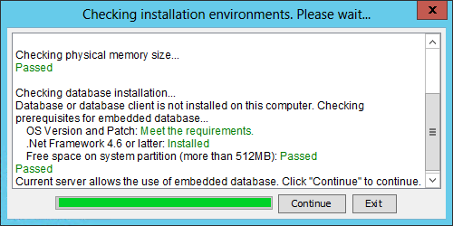
The IMC installation package provides a tool (envcheck) to check the system environment and database connectivity.
To use the envcheck tool:
1. Copy the envcheck tool (envcheck.bat for Windows or envcheck.sh for Linux) from the tools folder to the install folder of the IMC installation package.
2. Run the tool.
The Checking installation environments dialog box opens.
The system checks the port availability, free physical memory, and legacy database server or client.
After the checks are complete, the Checking installation parameters dialog box opens, as shown in Figure 1 and Figure 2. The following information uses Windows and Microsoft SQL Server as an example.
Figure 1 Checking installation parameters (local database)
Figure 2 Checking installation parameters (remote database)
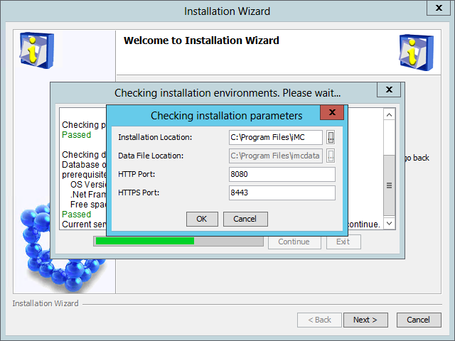
Figure 3 Checking installation parameters (embedded database)
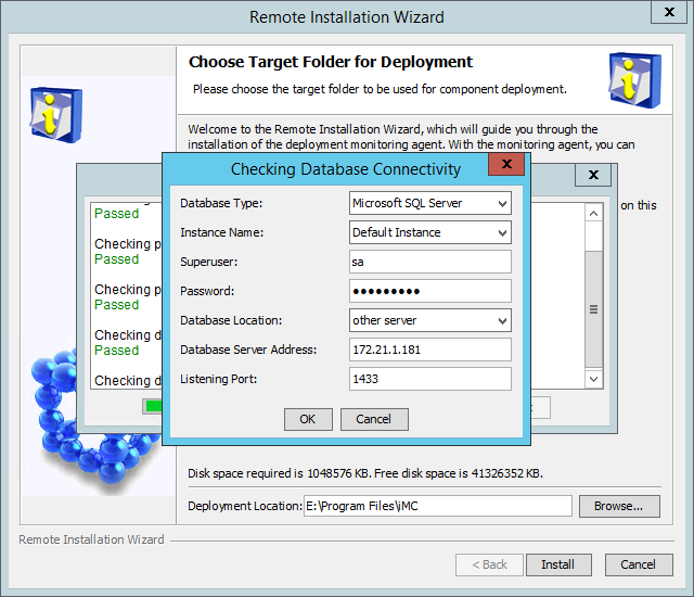
3. Configure the parameters for checking database connectivity:
|
|
IMPORTANT: For centralized deployment with embedded database, you only need to configure the installation location, data file location, and HTTP/HTTPS port. |
¡ Database Type—Select the database type. Options are Microsoft SQL Server, MySQL, and Oracle. The default is Microsoft SQL Server.
¡ Instance Name—To connect to the default instance of the database, select Default Instance. To connect to a named instance, select Other Instance, and then enter the instance name.
If you install IMC on Linux and use an Oracle database, configure the network service name and the tablespace name.
- You can select a network service name or click the Add Network Service Name icon ![]() to add a network
service name. For more information about configuring the network service name,
see Oracle 11g Installation and Configuration Guide
or Oracle 11g R2 Installation and Configuration Guide.
to add a network
service name. For more information about configuring the network service name,
see Oracle 11g Installation and Configuration Guide
or Oracle 11g R2 Installation and Configuration Guide.
- To connect to the default tablespace of the database, select Default Tablespace. To connect to a named tablespace, select Other Tablespace, and then enter the tablespace name.
¡ Superuser—Enter the database superuser name. The default is sa.
¡ Password—Enter the password of the superuser.
¡ Database Location—Select local host from the list when you use a local database, and select other server from the list when you use a remote database.
¡ Database Server Address—You do not need to configure this field when you use a local database. Enter the database server IP address when you use a remote database.
¡ Listening Port—Enter the listening port of the database server. The default is 1433.
¡ Installation Location—Specify the local directory for storing the IMC installation package.
¡ Data File Location—Specify the local directory for storing the data files.
¡ HTTP Port—Enter the HTTP port number for the IMC Web server. The default is 8080.
¡ HTTPS Port—Enter the HTTPS port number for the IMC Web server. The default is 8443.
4. Click OK.
The Checking installation environments dialog box displays the check results, as shown in Figure 4.
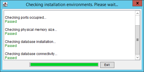
5. Click Exit.
Fix any failed check items according to the check results.
Superuser account
During the IMC platform installation, IMC uses the superuser account and password for database access, and then creates database files and user accounts for each deployed component. The deployed IMC platform subcomponents and service components use their own user accounts for database access.
If the password of the superuser account is changed after IMC deployment, be sure to update the password in IMC. If the password is not promptly updated, you cannot view database information on the Environment tab, deploy new components, or update existing components for IMC.
To update the database user password in IMC:
1. Start the Intelligent Deployment Monitoring Agent, and then click the Environment tab.
2. Click Change Password.
The Change Password button is displayed only when the Intelligent Deployment Monitoring Agent detects the incorrect database user password.
3. Enter the new database password, and then click OK, as shown in Figure 5 and Figure 6.
Figure 5 Changing the superuser password (local database)
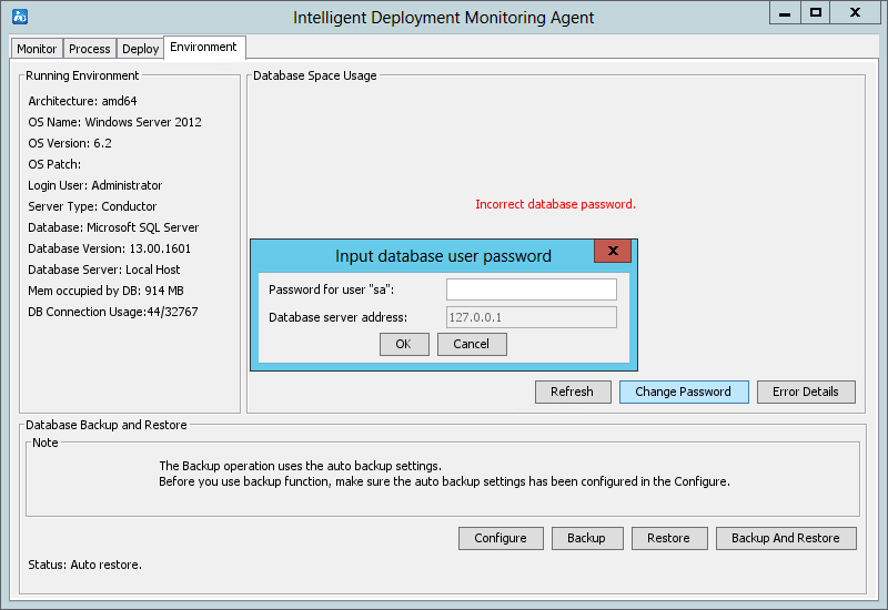
Figure 6 Changing the superuser password (remote database)
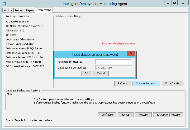
Table 12 lists the default superuser accounts of SQL Server, MySQL, and Oracle databases.
Table 12 Database superuser accounts
|
Database |
Superuser |
|
SQL Server |
sa |
|
Oracle |
· system · sys |
|
MySQL |
root |
Setting the system time
As a best practice, configure the following settings:
· Do not enable seasonal time adjustments such as daylight savings time.
· Before installing IMC, verify that the system time, date, and time zone settings on the server are correct.
Do not modify the system time on the server after IMC is started. If you modify the system time, the following issues might occur:
· When jumping to a future time, the system might get so occupied in processing the sudden burst of expired data that real-time data sampling will be delayed. The delay is automatically recovered after the processing of expired data is complete.
· When you modify the system time to a past time, data with overlapping time occurs, and data processing might become abnormal. After the overlapping time is past, data processing becomes normal again.
Installing and deploying the IMC platform
The following information describes how to install and deploy the IMC platform on a Windows host that is already installed with a SQL Server 2012 database.
In the distributed deployment scheme, once the database client is installed, you can install and deploy the IMC platform on the conductor server. Only some subcomponents of the IMC platform can be deployed on a member server. For more information, see Table 13.
Table 13 IMC platform subcomponents and deployment requirements
|
Component |
Subcomponents |
Deployment server |
|
IMC platform |
Resource Management |
Conductor |
|
Alarm Management |
Conductor or member |
|
|
User Selfservice Management |
Conductor or member |
|
|
Guest Access Management |
Conductor or member |
|
|
Intelligent Configuration Center |
Conductor |
|
|
Report Management |
Conductor |
|
|
NE Management |
Conductor |
|
|
Performance Management |
Conductor or member |
|
|
ACL Management |
Conductor or member |
|
|
Network Asset Management |
Conductor |
|
|
Security Control Center |
Conductor |
|
|
General Search Service Management |
Conductor or member |
|
|
Syslog Management |
Conductor or member |
|
|
VLAN Management |
Conductor or member |
|
|
WeChat Server |
Conductor or member |
|
|
NOTE: The IMC platform supports deploying multiple member servers, but each subcomponent can only be deployed on one server. |
Selecting the installation type
1. Log on to Windows as an administrator.
2. Run the install.bat script in the install directory of the IMC installation package.
The Select Country/Region, Language, and Installation Type dialog box appears, as shown in Figure 7.
Figure 7 Select Country/Region, Language, and Installation Type dialog box
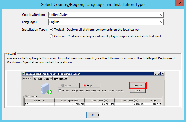
3. Select the country/region, language, and installation type.
IMC supports typical and custom installations.
¡ Typical—All platform subcomponents are automatically installed and deployed on the local host without manual intervention.
¡ Custom—You can select desired platform subcomponents to install on the local host. After installation is complete, manually deploy the platform subcomponents.
¡ In the distributed deployment mode, you must select the custom installation mode to install platform subcomponents as needed.
4. Click OK.
The IMC installation file does not have any special requirements for the transfer directory. Copy the installation file to the local server and then decompress it. You can decompress the file by using decompression software on Windows systems and the unzip command on Linux systems.
To install the IMC platform on a Linux host, use the following guidelines:
· Run the install.sh script in the install directory of the IMC installation package as a root user.
· If Linux is used, copy the IMC installation package to a local directory before you run the install.sh script.
· If the IMC installation package is transferred through FTP, grant read access to the install.sh script by executing chmod –R 775 install.sh in the directory of the script.
When you install or upgrade IMC, restart the IMC server if a socket issue exists in the IMC installation environment. If no socket issue exists, you do not need to restart the IMC server.
The installation packages of the following components are located in the tools\components directory: ACL, EUPLAT, GAM, RestPlugin, VLAN, and WeChat. Before you install and deploy the IMC platform, copy the installation packages of the components you want to install to the install\components directory.
Installing the IMC platform in typical mode
1. In the Select Country/Region, Language, and Installation Type dialog box, select the Typical installation type, and then click OK.
The Checking installation parameters dialog box opens, as shown in Figure 8 for local database and Figure 9 for remote database.
Figure 8 Checking installation environment (local database)
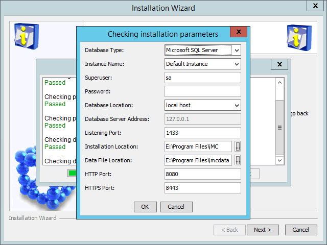
Figure 9 Checking installation environment (remote database)
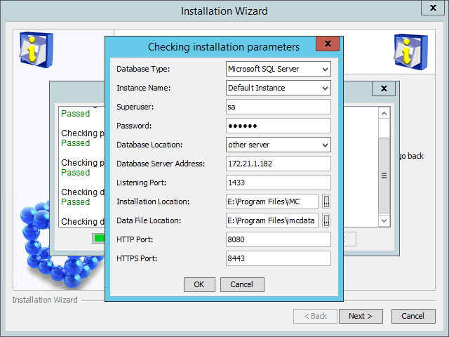
Figure 10 Checking installation parameters (embedded database)
2. Configure the parameters as needed, as shown in "(Optional.) Checking the installation environment."
3. Click OK.
The system checks the installation environment and database connectivity, and then displays the check results.
Fix any failed check items according to the check results.
After the checks are passed, the system installs and deploys all IMC platform subcomponents.
4. After IMC installation and deployment is complete, the Batch deploy succeeded dialog box opens, as shown in Figure 11.
Figure 11 Batch deploy succeeded

5. Click OK.
Installing the IMC platform in custom mode
Installing the IMC platform
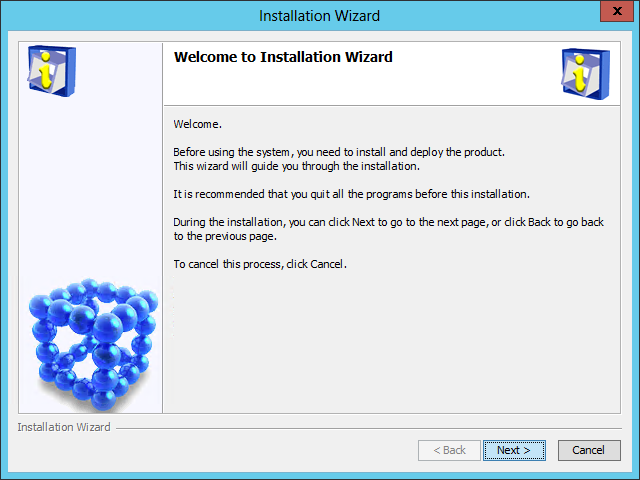
1. In the Select Country/Region, Language, and Installation Type dialog box, select the Custom installation type, and then click OK.
¡ For the local database scheme and remote database scheme, the Checking Database Connectivity dialog box opens, as shown in Figure 12 and Figure 13.
Figure 12 Checking Database Connectivity dialog box (local database)
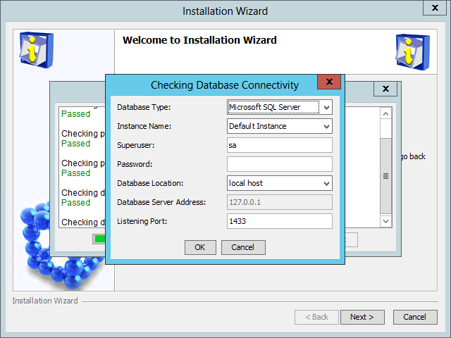
Figure 13 Checking Database Connectivity dialog box (remote database)

¡ For the embedded database scheme, the Checking installation environments dialog box opens, as shown in Figure 14.
Figure 14 Checking installation environments (embedded database)
2. Configure the parameters as needed, as shown in "(Optional.) Checking the installation environment."
3. Click OK.
The system checks the installation environment and database connectivity, and then displays the check results.
Fix any failed check items according to the check results.
After the checks are passed, the IMC installation wizard opens, as shown in Figure 15.
Figure 15 IMC installation wizard
4. Click Next.
The Agreement page opens, as shown in Figure 16.
Figure 16 Agreement page
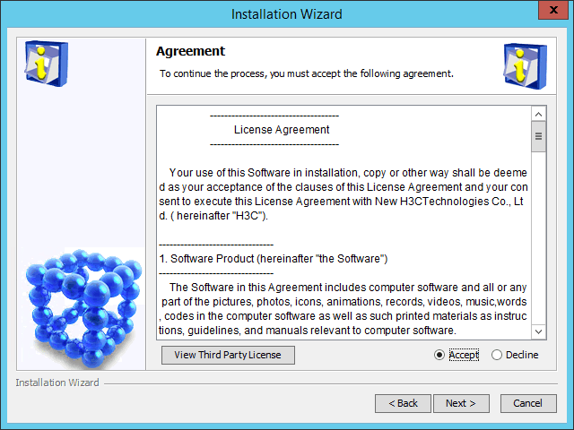
5. Read the license agreement, select Accept, and then click Next.
The Choose Target Folder page opens, as shown in Figure 17.
Figure 17 Choose Target Folder page
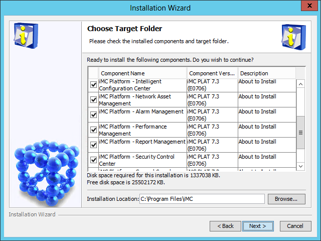
6. Select the components you want to install and specify a local path as the installation location.
The installation program checks whether the specified installation path contains any files. If the path contains files, a message is displayed. Click OK to delete the files.
The default installation location is X:\Program Files\iMC, where X is the drive letter of the disk with the largest amount of free space.
|
|
NOTE: · If you install the IMC platform on a Linux host, do not use a symlink path as the installation location. · In Linux, the default installation location is /opt/iMC. |
7. Click Next.
The Deployment and Upgrade Options page opens, as shown in Figure 18.
Figure 18 Deployment and Upgrade Options page
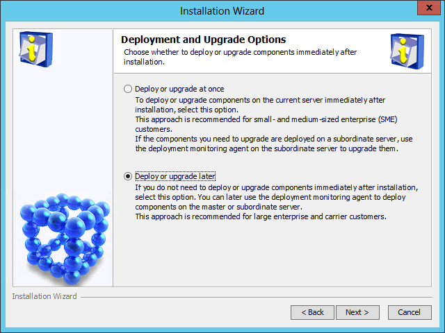
8. Select Deploy or upgrade later.
9. Click Next.
The Installation Summary page opens, as shown in Figure 19.
Figure 19 Installation Summary page

10. Verify the installation summary, and then click Install.
After the installation is complete, the Installation Completed page opens, as shown in Figure 20.
Figure 20 Installation Completed page
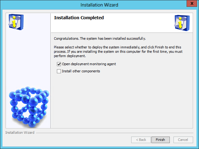
11. Select Open deployment monitoring agent, and then click Finish.
Deploying the IMC platform component
|
|
IMPORTANT: When IMC uses the distributed deployment scheme, you must deploy the IMC platform component on the conductor server. |
1. After the IMC platform is installed, the system automatically starts the Intelligent Deployment Monitoring Agent and displays the Batch deploy dialog box, as shown in Figure 21.
Figure 21 Batch deploy dialog box
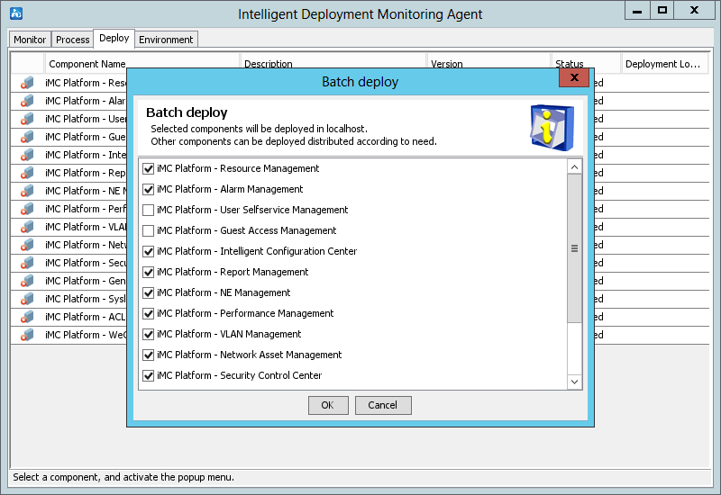
2. Select the components to be deployed (select the default components in this example), and then click OK.
The Database Configuration page opens, as shown in Figure 22 and Figure 23.
Figure 22 Database Configuration page (local database)
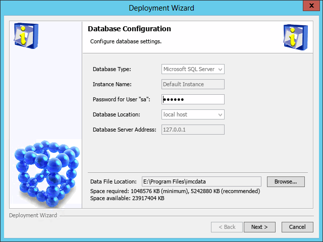
Figure 23 Database Configuration page (remote database)
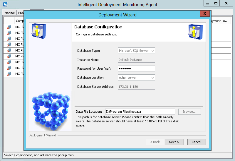
3. Enter the password of the superuser.
4. (Applicable to only IMC centralized deployment with embedded database.) Perform the following tasks:
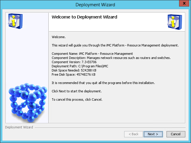
a. Click Cancel to exit the deployment wizard, and then click OK in the window that opens.
b. On the Deploy tab of the Intelligent Deployment Monitoring Agent window, right-click the resource management component, and then select Deploy, as shown in Figure 24.
Figure 24 Deploying the resource management component
c. In the confirmation dialog box that opens, click Yes.
The deployment wizard opens, as shown in Figure 25.
d. Click Next. The Database Configuration page opens, as shown in Figure 26.
Figure 26 Database Configuration page
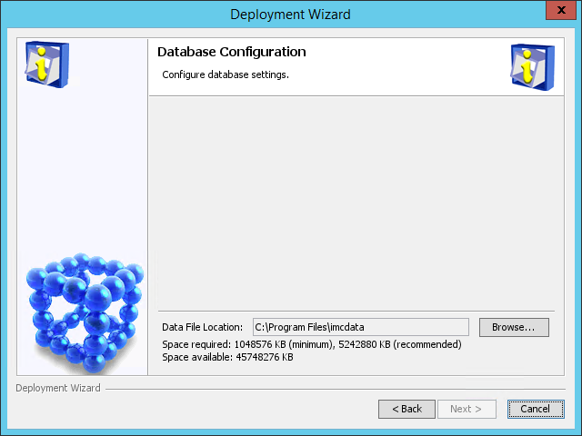
e. Click Back to return to the Deployment Wizard page, as shown in Figure 25, and then click Next to enter the Database Configuration page, as shown in Figure 27.
Figure 27 Database Configuration page
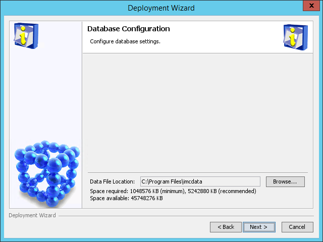
5. Set the data file location.
¡ Local database:
Make sure the specified data file location is on a readable, writable, and uncompressed disk drive and does not include any files.
The default data file location is X:\Program Files\imcdata, where X is the drive letter of the disk that has the largest amount of free space.
¡ Remote database:
Specify the directory on the database server for storing IMC data files. Make sure the specified data file location exists on the database server and does not include any files.
|
|
NOTE: On Linux, the default data file location is /opt/imcdata. |
6. Click Next. In the confirmation dialog box that opens, click OK.
The Configure Web Service Port page opens, as shown in Figure 28.
Figure 28 Configure Web Service Port page
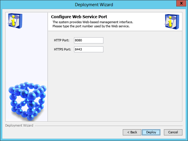
7. Enter the HTTP and HTTPS port numbers. This example uses the default port numbers 8080 and 8443.
If you specify other port numbers, make sure the specified ports are not used by other services.
8. (Applicable to only IMC centralized deployment with embedded database.) Perform the following tasks:
a. After the resource management component deployment is complete, click Finish to close the deployment wizard.
b. On the Deploy tab of the Intelligent Deployment Monitoring Agent window, right-click the component you want to deploy, and then select Batch Deploy. In the Batch deploy window that opens, select the target components, as shown in Figure 29.
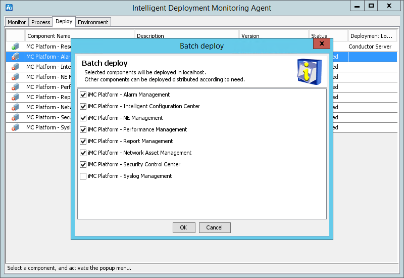
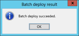
9. Click Deploy. After the deployment is complete, the Batch deploy succeeded dialog box opens, as shown in Figure 30.
Figure 30 Batch deploy succeeded dialog box

10. Click OK.
Deploying IMC on a member server (distributed deployment)
Before you deploy IMC subcomponents on a member server for the first time, install the Intelligent Deployment Monitoring Agent on the member server.
Make sure you have started IMC on the conductor server.
Starting the remote installation wizard
To start the remote installation wizard:
1. On the member server, right-click the installslave.bat script in the install directory of the installation package and select Run as Administrator.
The Address of Conductor page opens, as shown in Figure 31.
To start the remote installation wizard on Linux, run the installslave.sh script in the install directory of the installation package as a root user. If the installation file is obtained by using FTP, you must first authorize the installslave.sh script by executing the chmod –R 775 installslave.sh command in the directory of the script.
Figure 31 Address of Conductor
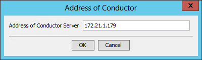
2. Enter the IP address of the conductor server, and then click OK.
The Checking Database Connectivity dialog box opens, as shown in Figure 32and Figure 33.
Figure 32 Checking installation environment (local database)

Figure 33 Checking Database Connectivity (remote database)
3. Configure the parameters as needed. For descriptions about the parameters, see "(Optional.) Checking the installation environment."
4. Click OK to start checking the database connectivity.
After the installation environment check is passed, the Remote Installation Wizard opens, which means that you have successfully started the remote installation wizard.
Installing the Intelligent Deployment Monitoring Agent
1. On the Choose Target Folder for Deployment dialog box shown in Figure 34, specify the deployment location for the Intelligent Deployment Monitoring Agent.
The default deployment location is the \Program Files\iMC directory of the disk with the maximum free space on Windows or is /opt/iMC on Linux. This example uses E:\Program Files\iMC.
The installation program examines whether the specified installation path contains files. If the path contains files, a message is displayed. Click OK to delete the files.
Figure 34 Choose Target Folder for Deployment
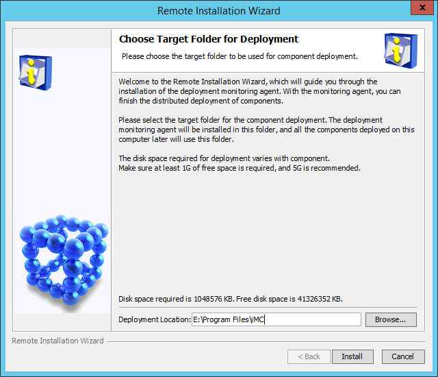
2. Click Install.
The system starts to download files. After the download, the Installation Completed dialog box opens, as shown in Figure 35.
Figure 35 Installation Completed
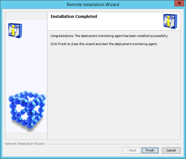
3. Click Finish.
Deploying the IMC platform subcomponents
1. Click the Deploy tab.
The Deploy tab displays information about all IMC components that have been installed.
2. Right-click a platform subcomponent that has not been deployed, and then select Batch Deploy from the shortcut menu.
The Batch deploy dialog box opens.
Figure 36 Batch deploy
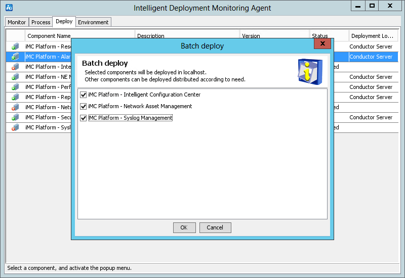
3. Select the subcomponents you want to deploy, and then click OK.
The system starts downloading the files.
4. After the download is complete, perform the following tasks on the Database Configuration page:
a. Enter the password for the user sa for the current database, which is the superuser name specified during IMC installation.
b. Set the data file location.
- Local database:
Make sure the specified data file location is on a
readable, writable, and uncompressed disk drive and does not include any files.
The default data file location is X:\Program Files\imcdata,
where X is the drive letter of the disk that has
the largest amount of free space.
- Remote database:
Specify the directory on the database server for
storing IMC data files. Make sure the specified data file location exists on
the database server and does not include any files.
|
|
NOTE: On Linux, the default data file location is /opt/imcdata. |
Figure 37 Database Configuration (local database)

Figure 38 Database Configuration page (remote database)

5. Click Next. On the Configure Web Service Port page that opens, set HTTP Port (8080 by default) and HTTPS Port (8443 by default) as needed.
Figure 39 Configure Web Service Port

6. Click Deploy to start the deployment.
After the deployment is finished, the Batch deploy result dialog box opens.
Figure 40 Batch deploy result
7. Click OK.
Managing IMC by using the Intelligent Deployment Monitoring Agent
The Intelligent Deployment Monitoring Agent is automatically installed after the IMC platform is installed.
As the IMC management and maintenance tool, the Intelligent Deployment Monitoring Agent provides IMC operation information as well as a variety of management options, such as:
· Starting and stopping IMC.
· Installing new components.
· Upgrading IMC components.
· Deploying and removing components.
Starting the Intelligent Deployment Monitoring Agent
To start the Intelligent Deployment Monitoring Agent, click Start, access the all applications page, and then select iMC > Deployment Monitoring Agent.
To start the Intelligent Deployment Monitoring Agent on Linux, run the dma.sh script in the /deploy directory of the IMC installation path.
As shown in Figure 41, the agent contains the following tabs: Monitor, Process, Deploy, and Environment. By default, the Monitor tab is displayed.
The following information describes the functionality of each tab.
Figure 41 Intelligent Deployment Monitoring Agent
|
|
NOTE: To start the Intelligent Deployment Monitoring Agent on Linux, run the dma.sh script in the /deploy directory of the IMC installation path. |
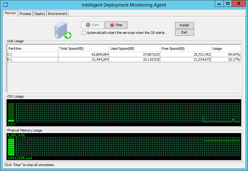
Monitor tab
As shown in Figure 42, the Monitor tab displays the performance information of the IMC server, including the disk, CPU, and physical memory usage information.
The tab also provides the following options:
· Start—Click this button to start IMC. This button is available when IMC is stopped.
|
|
IMPORTANT: For correct operation, start the Intelligent Management Server service with an account that has read/write permissions on the IMC installation folder. By default, the Intelligent Management Server service starts with the Local System account. |
· Stop—Click this button to stop IMC. This button is available when IMC is already started.
· Automatically start the services when the OS starts—Select this option to automatically start IMC when the operating system starts.
· Install—Click this button to install new components or upgrade existing components.
· Exit—Click this button to exit the Intelligent Deployment Monitoring Agent.
Figure 42 Monitor tab of the Intelligent Deployment Monitoring Agent

Process tab
As shown in Figure 43, the Process tab displays IMC process information.
Figure 43 Process tab of the Intelligent Deployment Monitoring Agent
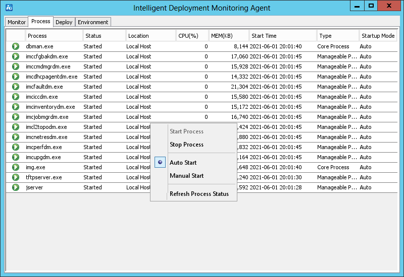
The right-click menu of a manageable process provides the following options:
· Start Process—Select this option to start the process. This option is available when the process is stopped.
· Stop Process—Select this option to stop the process. This option is available when the process is started.
· Auto Start—Select this option to enable automatic startup of the process when IMC is started.
· Manual Start—Select this option to require manual startup of the process.
· Refresh Process Status—Select this option to refresh the status of the process.
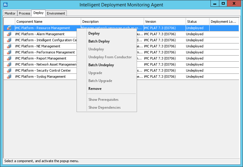
Deploy tab
As shown in Figure 44, the Deploy tab displays information about all deployed components.
Figure 44 Deploy tab of the Intelligent Deployment Monitoring Agent
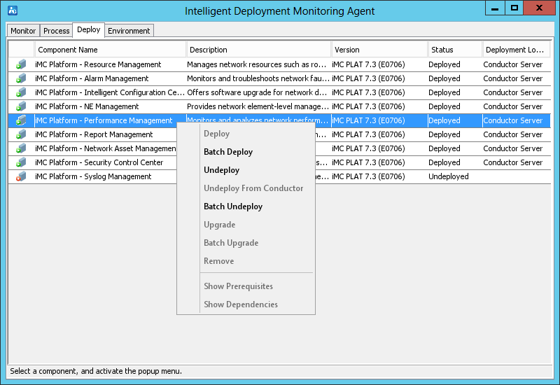
The right-click menu of a component provides the following options:
· Deploy—Select this option to deploy the component on the local host.
This option is available only when the selected component is in Undeployed state.
· Batch Deploy—Select this option to batch deploy components on the local host.
Components can be deployed only when they have been installed but in Undeployed state.
· Undeploy—Select this option to undeploy the component.
This option is available only when the selected component is in Deployed state.
· Undeploy From Conductor—Select this option to delete component deployment information from the conductor server.
This option is available only when the member server where the component is deployed cannot operate correctly.
· Batch Undeploy—Select this option to undeploy multiple components.
· Upgrade—Select this option to upgrade the component.
· Batch Upgrade—Select this option to upgrade components in batches.
· Remove—Select this option to remove the component from the host.
This option is available only when the selected component is in Undeployed state.
· Show Prerequisites—Select this option to view all components that the selected component depends on. The component can be deployed only after the dependent components have been deployed.
This option is unavailable if the component does not depend on any other components.
· Show Dependencies—Select this option to view all components that depend on the selected component.
This option is unavailable if no other components depend on the selected component.
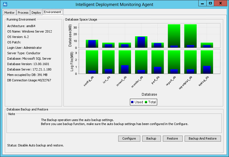
Environment tab
As shown in Figure 45 and Figure 46, the Environment tab displays the software, hardware, and database information for the current IMC server.
The tab also provides database backup and restoration options in the Database Backup and Restore area.
For more information about the Environment tab, see "Backing up and restoring the database."
Figure 45 Environment tab of the Intelligent Deployment Monitoring Agent (local database)
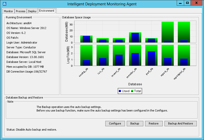
Figure 46 Environment tab of the Intelligent Deployment Monitoring Agent (remote database)
Installing and deploying IMC service components
The following information describes how to install and deploy the service components.
Deployment guidelines
Table 14 lists all service components and subcomponents in IMC.
|
|
NOTE: The subcomponents included vary by component version. |
Table 14 Service components and subcomponents (centralized deployment)
|
Component |
Subcomponent |
|
Endpoint Intelligent Access |
· User Access Manager: ¡ Intelligent Strategy Proxy ¡ User Access Management ¡ User Access Management Sub Server ¡ Portal Server ¡ EIP Server ¡ EIP Sub Server ¡ Policy Server ¡ User SelfService ¡ Third-Party Page Publish Server · TACACS+ Authentication Manager |
|
EAD Security Policy |
· Security Policy Configuration · Desktop Asset Manager · Desktop Asset Manager Proxy Server |
|
MPLS VPN Manager |
· MPLS Management · MPLS VPN Management · Intelligent Routing Management · MPLS TE Management · L2VPN Management |
|
IPsec VPN Manager |
IPsec VPN Manager |
|
Wireless Service Manager |
· Wireless Service Manager · Wireless Intrusion Prevention System · Wireless Location Manager · Wireless Location Engine |
|
User Behavior Auditor |
· User Behavior Auditor · User Behavior Auditor Server · Network Behavior Analyzer · Network Behavior Analyzer Server |
|
Application Manager |
· Application Management · Application Management Service |
|
Server & Storage Automation |
Server & Storage Automation |
|
Resource Configuration Management |
Configuration Management Database (CMDB) |
|
QoS Manager |
QoS Management |
|
Service Health Manager |
· Service Health Manager · NQA Collector Manager |
|
Branch Intelligent Management System |
· Branch Intelligent Management System · Auto-Configuration Server · Mobile Branch Manager |
|
VAN Fabric Manager |
VAN Fabric Manager |
|
Endpoint Mobile Office |
· Mobile Office Manager · Mobile Office MDM Proxy · Intelligent Strategy Proxy |
|
Security Service Manager |
· Security Service Manager · Load Balancing Manager |
|
Business Service Manager |
Business Service Manager |
|
IT Service Manager |
Self-Service Desk |
|
Intelligent Portal Manager |
· Intelligent Portal Manager · Intelligent Portal Authentication Manager · Intelligent Portal Authentication Backend |
|
Endpoints Profiling System |
· Endpoint Management · Scanner Engine |
Table 15 Service components and subcomponents (distributed deployment)
|
Component |
Subcomponent |
Optional server |
Quantity |
|||
|
Endpoint Intelligent Access |
User Access Manager |
Intelligent Strategy Proxy |
Conductor or member |
1 |
||
|
User Access Management |
Conductor or member |
1 |
||||
|
Portal Server |
Conductor or member |
10 |
||||
|
EIP Server |
Conductor or member |
1 |
||||
|
EIP Sub Server |
Member |
5 |
||||
|
Policy Server |
Conductor or member |
1 |
||||
|
User SelfService |
Conductor or member |
1 |
||||
|
Third-Party Page Publish Server |
Conductor or member |
10 |
||||
|
TACACS+ Authentication Manager |
TACACS+ Authentication Manager |
Conductor or member |
1 |
|||
|
EAD Security Policy |
Security Policy Configuration |
Conductor or member |
1 |
|||
|
Desktop Asset Manager |
Conductor or member |
1 |
||||
|
Desktop Asset Manager Proxy Server |
Conductor or member |
N |
||||
|
MPLS VPN Manager |
MPLS VPN Management |
Conductor or member |
1 |
|||
|
MPLS TE management |
Conductor or member |
1 |
||||
|
L2VPN Management |
Conductor or member |
1 |
||||
|
IPsec VPN Manager |
IPsec VPN Manager |
Conductor or member |
1 |
|||
|
Wireless Service Manager |
Wireless Service Manager |
Conductor or member |
1 |
|||
|
Wireless Intrusion Prevention System |
Conductor or member |
1 |
||||
|
Wireless Location Manager |
Conductor or member |
1 |
||||
|
Wireless Location Engine |
Conductor or member |
20 |
||||
|
Network Traffic Analyzer |
Network Traffic Analyzer |
Conductor |
1 |
|||
|
Network Traffic Analyzer Server |
Conductor or member |
10 |
||||
|
Network Behavior Analyzer |
Conductor |
1 |
||||
|
Network Behavior Analyzer Server |
Conductor or member |
10 |
||||
|
User Behavior Auditor |
User Behavior Auditor |
Conductor |
1 |
|||
|
User Behavior Auditor Server |
Conductor or member |
10 |
||||
|
Network Behavior Analyzer |
Conductor |
1 |
||||
|
Network Behavior Analyzer Server |
Conductor or member |
10 |
||||
|
Application Manager |
Application Management |
Conductor |
1 |
|||
|
Application Management Service |
Conductor or member |
500 |
||||
|
Server & Storage Automation |
Server & Storage Automation |
Conductor |
1 |
|||
|
Resource Configuration Management |
Configuration Management Database (CMDB) |
Conductor or member |
1 |
|||
|
QoS Manager |
QoS Management |
Conductor or member |
1 |
|||
|
Branch Intelligent Management System |
Branch Intelligent Management System |
Conductor or member |
1 |
|||
|
Auto-Configuration Server |
Conductor or member |
15 |
||||
|
Mobile Branch Manager |
Conductor or member |
1 |
||||
|
VAN Fabric Manager |
VAN Fabric Manager |
Conductor or member |
1 |
|||
|
Endpoint Mobile Office |
Mobile Office Manager |
Conductor or member |
5 |
|||
|
Mobile Office MDM Proxy |
Conductor or member |
5 |
||||
|
Intelligent Strategy Proxy |
Conductor or member |
1 |
||||
|
Security Service Manager |
Security Service Manager |
Conductor or member |
1 |
|||
|
Load Balancing Manager |
Conductor or member |
1 |
||||
|
Business Service Manager |
Business Service Manager |
Conductor |
1 |
|||
|
IT Service Manager |
Self-Service Desk |
Conductor or member |
1 |
|||
|
Intelligent Portal Manager |
Intelligent Portal Manager |
Conductor |
1 |
|||
|
Intelligent Portal Authentication Manager |
Conductor or member |
1 |
||||
|
Intelligent Portal Authentication Backend |
Conductor or member |
10 |
||||
|
Endpoints Profiling System |
Endpoint Management |
Conductor or member |
1 |
|||
|
Scanner Engine |
Conductor or member |
1 |
||||
All service components can be installed in the same way, but their deployment procedure might differ. Based on the deployment procedure, the service components can be classified into several categories, as listed in Table 16.
Table 16 Service components classified by deployment procedure
|
Example component |
Similar components |
|
BIMS |
IVM, WSM, EPON, QoSM, VFM, SSM, BSM, ITSM, U-Center |
|
UAM |
EMO, EAD, TAM, IPM, EPS |
|
MVM |
N/A |
The following information describes how to install and deploy BIMS, UAM, and MVM.
|
|
IMPORTANT: U-Center must be deployed on IMC PLAT 7.3 (E0706P09). Before deploying U-Center, upgrade the platform to this version. |
Installing and deploying IMC BIMS
Installing IMC BIMS
1. Start the Intelligent Deployment Monitoring Agent, and then click Install on the Monitor tab.
The Choose folder dialog box opens, as shown in Figure 47.
Figure 47 Choose folder dialog box
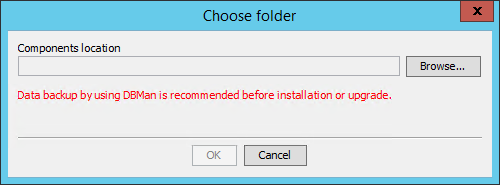
2. Click Browse, and then select the install\components folder in the BIMS installation package.
3. Click OK.
The IMC installation wizard opens, as shown in Figure 48.
Figure 48 IMC installation wizard

4. Click Next.
The Agreement page opens, as shown in Figure 49.
Figure 49 Agreement page
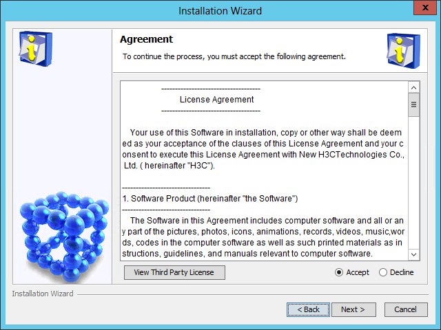
5. Read the license agreement and third-party license, and then select Accept.
6. Click Next.
The Choose Target Folder page opens, as shown in Figure 50.
The Installation Location field is automatically populated with the installation location of the IMC platform and cannot be modified.
Figure 50 Choose Target Folder page
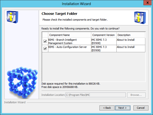
7. Select the BIMS subcomponents you want to install in the component list.
8. Click Next.
The Deployment and Upgrade Options page opens, as shown in Figure 51.
Figure 51 Deployment and Upgrade Options page

9. Select Deploy or upgrade later.
10. Click Next.
The Installation Summary page opens, as shown in Figure 52.
Figure 52 Installation Summary page
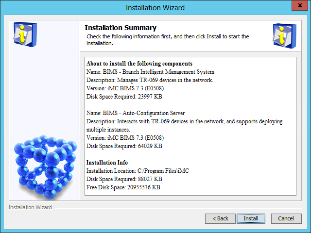
11. Verify the installation information, and then click Install.
After the installation is complete, the Installation Completed page opens, as shown in Figure 53.
Figure 53 Installation Completed page

Deploying IMC BIMS on the conductor server
1. Select Open deployment monitoring agent, and then click Finish.
The system automatically starts the Intelligent Deployment Monitoring Agent and displays the Batch deploy page, as shown in Figure 54.
Figure 54 Batch deploy dialog box
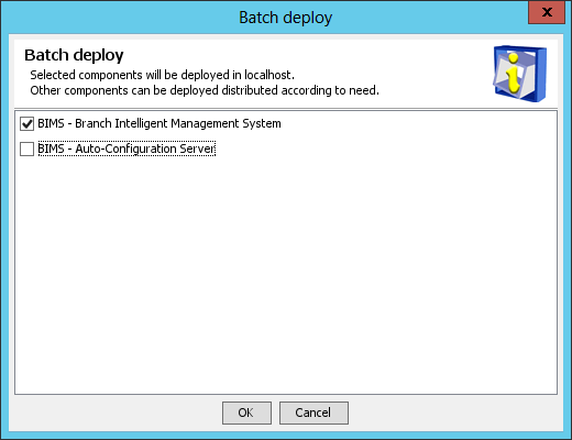
2. Select the BIMS subcomponents you want to deploy. In this example, select Branch Intelligent Management System.
3. Click OK.
The system starts to deploy the selected BIMS subcomponents.
After the deployment is complete, the Batch deploy succeeded dialog box opens, as shown in Figure 55.
Figure 55 Batch deploy succeeded dialog box
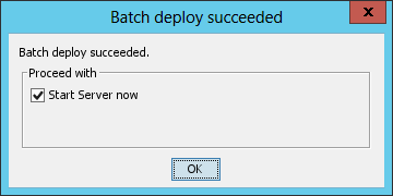
4. Select Start Server now, and then click OK.
Deploying BIMS subcomponents on a member server
1. In the Intelligent Deployment Monitoring Agent, click the Deploy tab.
The Deploy tab displays all IMC components that have been installed and their deployment information.
2. Right-click any component in the list, and then select Batch Deploy from the shortcut menu.
The Batch deploy page displays components that are not deployed, as shown in Figure 56.
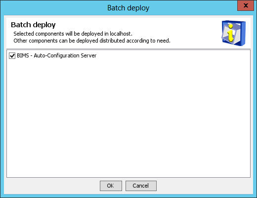
3. Select the BIMS subcomponents you want to deploy on the member server. In this example, select Auto-Configuration Server.
4. Click OK.
The Configure Web Service Port page opens, as shown in Figure 57.
Figure 57 Configure Web Service Port page

5. Enter the HTTP and HTTPS port numbers. This example uses the default port numbers 8080 and 8443.
If you specify other port numbers, make sure the specified ports are not used by other services.
6. Click Deploy.
After the deployment is finished, the Batch deploy result dialog box prompting Batch deploy succeeded opens.
Figure 58 Batch deploy result

7. Click OK.
Installing and deploying IMC UAM
Install IMC UAM in the same way IMC APM is installed. For information about the installation procedures, see "Installing and deploying IMC BIMS."
Deploying UAM subcomponents on the conductor server
1. On the Installation Completed page shown in Figure 59, select Open deployment monitoring agent, and then click Finish.
Figure 59 Installation Completed page
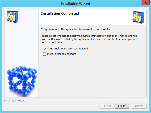
The Batch deploy dialog box opens, as shown in Figure 60.
Figure 60 Batch deploy dialog box
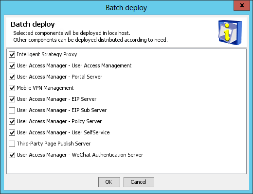
2. Select the UAM subcomponents you want to deploy, and then click OK.
Because the EIP Sub Server can be deployed only on member servers in distributed deployment, do not select it.
The IMC deployment wizard starts and displays the Intelligent Strategy Proxy Configuration page, as shown in Figure 61.
Figure 61 Intelligent Strategy Proxy Configuration page
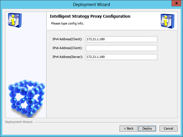
3. Configure the following parameters:
¡ IPv4 Address(Client)—Enter the IP address of the Intelligent Strategy Proxy component. By default, this field is automatically populated with the IP address of the local host.
¡ IPv4 Address(Server)—Enter the IP address of the User Access Management component. By default, this field is automatically populated with the IP address of the local host.
Modify the default settings only when the local host has multiple network interface cards (NICs) and you want to associate Intelligent Strategy Proxy and User Access Management with different NICs.
4. Click Deploy.
The Configure User Access Management page opens, as shown in Figure 62.
Figure 62 Configure User Access Management page
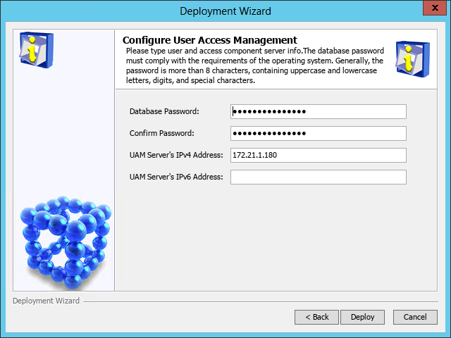
5. Configure the following parameters:
¡ Database Password/Confirm Password—These fields are automatically populated with the password of the database superuser sa specified during IMC platform installation.
If the database user password is changed after IMC platform installation, enter the new password in these fields.
¡ UAM Server's IPv4 Address—This field is automatically populated with the IP address of the local host.
6. Click Deploy.
The Configure Portal Component page opens, as shown in Figure 63.
Figure 63 Configure Portal Component page

7. Use the default settings, and then click Deploy.
The Configure EIP Server page opens, as shown in Figure 64.
Figure 64 Configure EIP Server page

8. Use the default settings, and then click Deploy.
The Configure Policy Server page opens, as shown in Figure 65.
Figure 65 Configure Policy Server page
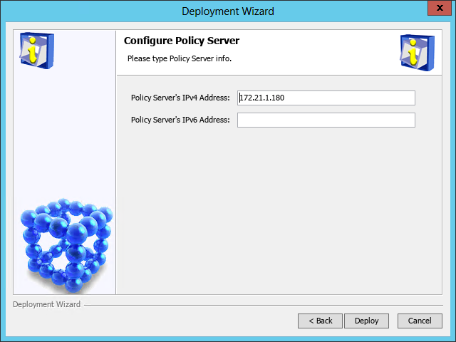
9. Use the default settings, and then click Deploy.
The Configure User SelfService page opens, as shown in Figure 66.
Figure 66 Configure User SelfService page

10. Use the default settings, and then click Deploy.
The Configure WeChat Authentication Server page opens, as shown in Figure 67.
Figure 67 Configure WeChat Authentication Server page
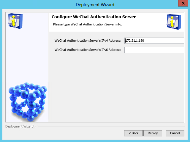
11. Use the default settings, and then click Deploy.
All the selected UAM subcomponents are deployed.
The Batch deploy succeeded dialog box opens, as shown in Figure 68.
Figure 68 Batch deploy succeeded dialog box
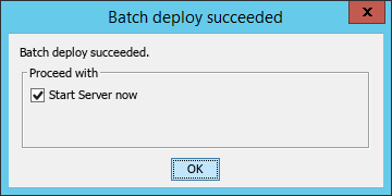
12. Configure the Start Server now option as needed, and then click OK.
Deploying UAM subcomponents on a member server
1. In the Intelligent Deployment Monitoring Agent, click the Deploy tab.
The Deploy tab displays information about all IMC components that have been installed.
2. Right-click a component that is not deployed, and then select Batch Deploy from the shortcut menu.
The Batch deploy dialog box opens, as shown in Figure 69.
Figure 69 Batch deploy dialog box
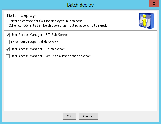
3. Select the UAM subcomponents you want to deploy.
In this example, select Portal Server and EIP Sub Server.
4. Click OK.
The system starts to deploy the selected UAM subcomponents.
During the deployment progress, the Configure Web Service Port page opens, as shown in Figure 70.
Figure 70 Configure Web Service Port page

5. Configure the HTTP port and HTTPS port, and then click Next.
The Configure EIP server page opens, as shown in Figure 71.
Figure 71 Configure EIP Server page

6. Verify that the EIP server and the member server have been locally deployed, and then click Next.
The Configure EIP Server page opens, as shown in Figure 72.
Figure 72 Configure EIP Server page
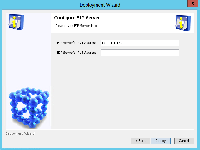
7. Enter the IP address of the EIP Sub Server component in the EIP Server's IPv4 Address field.
By default, this field is automatically populated with the IP address of the local host.
8. Click Deploy.
The Configure Portal Component page opens, as shown in Figure 73.
Figure 73 Configure Portal Component page

9. Enter the IP address of the host where portal server is to be deployed in the Portal Server's IPv4 Address field. By default, this field is automatically populated with the IP address of the local host.
After the deployment is complete, the batch deploy result dialog box opens, as shown in Figure 74.
Figure 74 Batch deploy result dialog box

10. Click OK.
Installing and deploying IMC MVM
Installing IMC MVM
Install IMC MVM in the same way IMC BIMS is installed. For information about the installation procedure, see "Installing and deploying IMC BIMS."
Deploying MVM
MVM subcomponents can be deployed on both the conductor and member servers. The following information only describes deploying subcomponents on the conductor server. You can deploy MVM on a member server in the same way it is deployed on the conductor server.
To deploy MVM:
1. On the Installation Completed page shown in Figure 75, select Open deployment monitoring agent and click Finish.
Figure 75 Installation Completed page

The Batch deploy dialog box opens, as shown in Figure 76.
Figure 76 Batch deploy dialog box
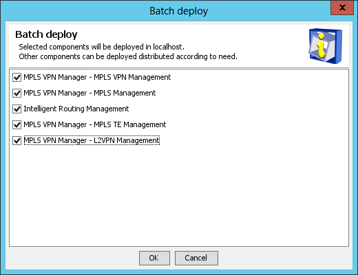
2. Select the MVM subcomponents you want to deploy, and then click OK.
In this example, select all the MVM subcomponents.
The Please Choose L2VPN Global Parameter Operate page opens, as shown in Figure 77.
Figure 77 Please Choose L2VPN Global Parameter Operate page
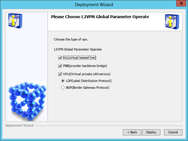
3. Configure the L2VPN parameters as needed. VPLS can use either LDP or BGP for signaling. When BGP is selected, the VLL and PBB options become unavailable.
4. Click Deploy. After the deployment is complete, the Batch deploy succeeded dialog box opens, as shown in Figure 78.
Figure 78 Batch deploy succeeded dialog box

5. Configure the Start Server now option as needed, and then click OK.
Installing plug-ins
Installing DHCP plug-ins
To enable IMC to obtain endpoint names from a DHCP server, install the DHCP plug-in on the DHCP server.
Restrictions and guidelines
For IMC to obtain endpoint names from a DHCP server correctly, the following requirements must be met:
· The DHCP server must exist, and it is the only DHCP server that has the DHCP plug-in installed and is reachable from the IMC server.
· The DHCP Server service and iMC DHCP Plug service are enabled on the DHCP server.
· The DHCP server is added to IMC and its configuration is synchronized to IMC.
· The IMGAddress value in file server\imf\server\conf\imf.cfg on the DHCP server is set correctly.
By default, IMC does not obtain reserved or allocated IP addresses from the DHCP server. To enable IMC to obtain such addresses, perform the following tasks:
1. On the DHCP server, set the value of GetDHCPAllocAndReservedIpInfoFlag to 1 in file server\imf\server\conf\ dhcp_agent.cfg.
2. Restart the iMC DHCP Plug service on the DHCP server.
3. On the IMC server, synchronize the DHCP server configuration to IMC.
Installing a DHCP plug-in on an MS DHCP server
1. On the conductor IMC server, edit the qvdm.conf file to enable IMC to obtain endpoint names or FQDNs from DHCP servers:
a. In the\server\conf\ directory of the IMC installation path, use Notepad to open the qvdm.conf file.
b. Add the following line to the file:
l2topoPCNameDhcpSwitch=1
c. Save and close the file.
d. Restart IMC in the Intelligent Deployment Monitoring Agent.
2. On the MS DHCP server, edit the imf.cfg file so that the DHCP server can communicate with IMC:
a. Transfer the plug-in installation package dhcp-plug-windows.zip from the \windows\tools\ directory of the IMC installation package on the IMC server to the MS DHCP server.
b. Decompress the installation package.
c. Use Notepad to open the imf.cfg file in the \dhcp-plug-windows\server\imf\server\conf directory.
d. Edit the imf.cfg file as follows:
- Set the value of IMGAddress to the IP address of the conductor IMC server.
- Set the value of IMGPort to the IMG port number, which is 8800 by default.
e. Save and close the file.
3. Run the install.bat script in the dhcp-plug-windows directory.
After the installation is complete, a new service iMC DHCP Plug is added to the system services.
4. Start the iMC DHCP Plug service:
a. Click Start, and then select Administrative Tools > Component Services.
b. On the Component Services page, select Services (Local) from the navigation tree.
c. On the Services (Local) list, right-click the iMC DHCP Plug service and select Start.
To uninstall the DHCP plug-in, run the uninstall.bat script in the dhcp-plug-windows directory.
|
|
IMPORTANT: Do not delete the directory where the plug-in installation package dhcp-plug-windows.zip is decompressed. If you delete the directory, you cannot uninstall the DHCP plug-in completely. |
Installing a DHCP plug-in on a Linux DHCP server
1. On the conductor IMC server, edit the qvdm.conf file to enable IMC to obtain endpoint names or FQDNs from DHCP servers:
a. In the \server\conf directory of the IMC installation path, use Notepad to open the qvdm.conf file.
b. Add the following line to the file:
l2topoPCNameDhcpSwitch=1
c. Save and close the file.
d. Restart IMC in the Intelligent Deployment Monitoring Agent.
2. On the Linux DHCP server, edit the imf.cfg file so that the DHCP server can communicate with IMC.
a. Transfer the plug-in installation package dhcp-plug-linux.zip from the tools directory of the IMC installation package on the IMC server to the Linux DHCP server.
b. Decompress the installation package.
c. Use the vi editor to open the imf.cfg file in the /dhcp-plug-linux/server/imf/server/conf/ directory.
vi imf.cfg
d. Edit the imf.cfg file:
- Set the value of IMGAddress to the IP address of the conductor IMC server.
- Set the value of IMGPort to the IMG port number, which is 8800 by default.
e. Save and close the file.
3. Set the path of the dhcpd.leases file, which stores DHCP address allocation information:
a. Determine the path of the dhcpd.leases file. The default path is /var/lib/dhcp.
b. Use the vi editor to open the qvdm.conf file in the /dhcp-plug-linux/server/imf/server/conf/ directory, and then add the following line to the file:
DhcpPlugIpAllocPath=<file path>/dhcpd.leases
Replace <file path> with the path of the dhcpd.leases file.
c. Save and close the file.
4. Run the install.sh script in the dhcp-plug-linux directory.
After the installation is complete, the system automatically starts the dhcp-plug service and adds the service to the system services.
To manually start the dhcp-plug service, execute the service dhcp-plug start command.
To stop the dhcp-plug service, execute the service dhcp-plug stop command.
To uninstall the DHCP plug-in, run the uninstall.sh script in the dhcp-plug-linux directory of the plug-in installation package.
|
|
IMPORTANT: · Do not delete the directory where the plug-in installation package dhcp-plug-linux.zip is decompressed. If you delete the directory, you cannot uninstall the DHCP plug-in completely. · You cannot configure the Linux DHCP server by using the Terminal Access > DHCP Configuration feature. |
Installing LLDP plug-ins
If topology calculation fails for displaying connection to servers, install an LLDP plug-in.
An LLDP plug-in contains the following packages:
· lldp-agent-redhat.zip
· lldp-agent-ubuntu.zip
· lldp-agent-windows.zip
Packages lldp-agent-redhat.zip and lldp-agent-ubuntu.zip apply to KVM servers and the lldp-agent-windows.zip package applies to Microsoft Hyper-V servers.
Before you install the LLDP plug-ins, save and decompress the packages to the target servers.
Make sure the lldp-agent-windows.zip package is saved to a non-system disk.
|
|
IMPORTANT: Do not delete the folder where the decompressed installation packages are located after the LLDP agent installation. If you delete the folder, the LLDP plug-ins cannot be uninstalled completely. |
Installing an LLDP Windows agent
LLDP Windows agents support 32-bit and 64-bit Windows operating systems.
To install and configure an LLDP Windows agent:
1. Run the install.bat script in the LLDP Windows agent installation path.
The LLDP Windows agent is installed.
2. Configure the LLDP Windows agent.
The LLDP Windows agent supports either LLDP or CDP, but not both at the same time. By default, the agent supports LLDP.
To enable the LLDP agent to support CDP and set the packet sending interval:
a. Open the lldpagent.conf file in the \Program Files\lldpAgent\ directory on the Windows system disk.
b. Delete the pound sign (#) from the string #Agent=CDP.
c. Delete the pound sign (#) from the string #INTERVAL=10, and then set the interval as needed.
The default setting is 300 seconds.
d. Save and close the file.
3. Restart the lldp-agent service.
Installing an LLDP Linux agent
The installation procedures for packages lldp-agent-redhat.zip and lldp-agent-ubuntu.zip are the same. The following information describes the installation procedure for the lldp-agent-redhat.zip package.
An LLDP Linux agent must be installed on 64-bit Linux, including Red Hat 5.5, Ubuntu 11.0, and their later versions.
To install and configure an LLDP Linux agent:
1. Set the executable permission to the install.sh script, and then run the script in the LLDP Linux agent installation path.
The LLDP Linux agent is installed.
2. Configure the LLDP Linux agent.
The LLDP Linux agent supports either LLDP or CDP, but not both at the same time. By default, the agent supports LLDP.
To enable the LLDP agent to support CDP and set the packet sending interval:
a. Open the lldpagent.conf file in the conf directory.
vi lldpagent.conf
b. Delete the pound sign (#) from the string #Agent=CDP.
c. Delete the pound sign (#) from the string #INTERVAL=10, and then set the interval as needed.
The default setting is 300 seconds.
d. Save and close the file.
3. Restart the lldp-agent service.
service lldp-agent restart
Accessing IMC
IMC is a browser-based management tool accessible from PCs. IMC of the Professional edition is also accessible from a mobile device.
Hardware, software, and browser requirements
Table 17 lists the hardware, software, and browser requirements for accessing IMC.
Table 17 Requirements for accessing IMC from a PC
|
OS |
Hardware and software |
Browser version |
Browser setting requirements |
|
Windows |
· Recommended resolution: 1280 pixels in width. · Base frequency ≥ 2 GHz, memory size ≥ 2 GB, hard disk size ≥ 50 GB, 48 × optical drive, 100 M NIC, and sound card · JRE 1.7.0_update76 or later is installed. |
· IE 10 or 11 · Firefox 50 or later · Chrome 44 or later |
· Turn off the popup blocker. · Enable Cookies. · Add IMC as a trusted site. |
Accessing IMC from a PC
Accessing IMC
1. Enter a Web address in either of the following formats in the address bar of the browser:
¡ http://ip-address:port/imc
¡ https://ip-address:port/imc
In the Web address, ip-address is the IP address of the conductor IMC server, and port is the HTTP or HTTPS port number used by IMC. By default, IMC uses HTTP port 8080 and HTTPS port 8443.
The IMC login page opens.
2. Enter the user name and password, and then click Login.
The default username for the IMC super administrator is admin. For versions earlier than IMC PLAT 7.3 (E0706), the default password is admin. For IMC PLAT 7.3 (E0706) and later versions, the default password is Pwd@12345.
|
|
IMPORTANT: · For security purposes, change the password of the IMC superuser admin immediately after the first login. · When you attempt to access IMC using HTTPS, a certificate error message might be displayed. For more information, see H3C Getting Started Guide. |
Accessing the UAM self-service center
When the UAM User SelfService subcomponent is deployed, access the user self-service center by entering a Web address in either of the following formats in the browser's address bar:
· http://ip-address:port
· http://ip-address:port/selfservice
In the Web address, ip-address is the IP address of the conductor IMC server where the UAM User SelfService subcomponent is deployed and port is the HTTP port number used by IMC.
Accessing IMC from a mobile device
1. Open the browser on the mobile device.
2. Enter http://ip-address:port/imc in the browser's address bar.
In the Web address, ip-address is the IP address of the IMC server and port is the HTTP port number of IMC. The default HTTP port number is 8080.
The IMC login page opens.
3. Enter the user name and the password in Operator and Password fields.
The operator must have been added to IMC. The operator account used for login must belong to an operator group that has the iMC Platform - Resource Management > Mobile Client Access operation privilege.
4. Select Mobile or PC as needed.
The PC version of IMC requires complex operations and provides all functions. The mobile version of IMC allows you to perform the following operations:
¡ View information about faulty devices and interfaces.
¡ Query devices.
¡ View device alarms.
¡ Receive real-time alarms.
¡ Test device reachability by using a ping or tracert command.
¡ View custom views and device views.
5. Click Login.
Securing IMC
As a best practice, perform the following tasks to secure IMC:
· Change the password of the IMC superuser admin immediately after the first login.
· Tie the administrative accounts to a central AAA server through LDAP or RADIUS.
· Retain one administrative account (not named admin) with a local password to recover from loss of access to the AAA server.
· Enable the verification code feature on the IMC login page. For more information, see H3C IMC Getting Started Guide.
Displaying a user agreement
A user agreement on the IMC login page informs operators of the rights and obligations for an IMC login. To log in to IMC, operators must accept terms of the user agreement.
To display a user agreement on the IMC login page:
1. On the conductor IMC server, enter the \client\conf directory of the IMC installation path (/client/conf on Linux).
2. Use Notepad (or vi on Linux) to open the commonCfg.properties file.
3. Change the value of the enableTerms parameter to true.
4. Save and close the commonCfg.properties file.
5. Prepare a user agreement in HTML format named terms.html.
6. Save the terms.html file to the \client\web\apps\imc directory of the IMC installation path (/client/web/apps/imc on Linux) on the conductor IMC server.
7. Display the IMC login page.
A User agreement link is displayed, as shown in Figure 79. Operators can click the link to view terms of the user agreement.
Figure 79 Viewing the user agreement on the login page
Upgrading IMC
The following example describes how to upgrade the IMC platform. Upgrade IMC service components in the same way the IMC platform is upgraded.
Preparing for the upgrade
Before you upgrade the IMC platform, complete the following tasks:
· Obtain the upgrade packages for the IMC platform and all the deployed service components. After the IMC platform upgrade, upgrade all the service components to match the new IMC platform version.
· Back up the IMC database files using DBMan manual backup (see "Backing up and restoring the database"). Stop all IMC processes, and then save the IMC installation directory to a backup path. If the upgrade fails, you can use these files to restore IMC.
Upgrading IMC
|
|
CAUTION: · Make sure you have compatible upgrade packages for all deployed IMC components. If components do not have upgraded packages, they cannot be upgraded after the IMC platform upgrade and might become invalid. · Do not upgrade IMC by running the install\install.bat script in the IMC installation path. · If the reporting function of an upgraded service component relies on the Report Management component, upgrade the Report Management component to match the service component version. |
You can use one of the following methods to upgrade components that are installed in the tools\components directory:
· Copy files of the following components from the tools\components directory to the IMC installation directory install\components: ACL, EUPLAT, GAM, RestPlugin, VLAN, and WeChat. These components are upgraded when you upgrade the IMC platform.
· Click Install in the Monitor tab of the Intelligent Deployment Monitoring Agent and select to upgrade components in the tools\components directory.
Upgrading the IMC platform
1. Start the Intelligent Deployment Monitoring Agent on the conductor server, and then click Install on the Monitor tab.
The Choose folder dialog box opens, as shown in Figure 80.
Figure 80 Choose folder dialog box

2. Click Browse, and then select the install\components directory in the upgrade package.
3. Click OK.
The IMC installation wizard opens, as shown in Figure 81.
Figure 81 IMC installation wizard

4. Click Next.
The Agreement page opens, as shown in Figure 82.
Figure 82 Agreement page

5. Read the license agreement, select Accept, and then click Next.
The Upgrade Common Components dialog box opens, as shown in Figure 83.
|
|
NOTE: Common components include the Intelligent Deployment Monitoring Agent and common background services. |
Figure 83 Upgrade Common Components dialog box
6. Click OK.
The system automatically upgrades common components and displays the upgrade progress, as shown in Figure 84.
Figure 84 Upgrading common components

After the common components are upgraded, the Choose Target Folder page opens, as shown in Figure 85.
The page displays the components whose upgrade packages are to be installed and the installation location.
Figure 85 Choose Target Folder page

7. Verify the information, and then click Next.
The Deployment and Upgrade Options page opens, as shown in Figure 86.
Figure 86 Deployment and Upgrade Options page

8. Select Deploy or upgrade at once, and then click Next.
The Installation Summary page opens, as shown in Figure 87.
Figure 87 Installation Summary page
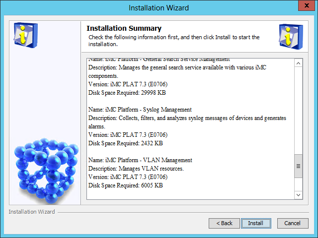
9. Verify the installation summary, and then click Install.
After the installation is complete, the Batch upgrade dialog box opens, as shown in Figure 88.
Figure 88 Batch upgrade dialog box
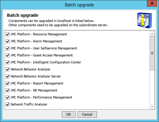
10. Select the components you want to upgrade, and then click OK.
After the upgrade is complete, the Batch upgrade result dialog box shown in Figure 89 or Figure 90 opens. The dialog box content varies depending on whether auto backup and restoration settings have been configured in DBMan before the upgrade.
Figure 89 Batch upgrade result
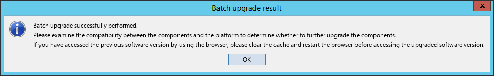
Figure 90 Batch upgrade result with auto backup and restoration
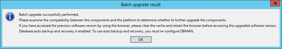
11. Click OK.
12. If the Auto Backup and Restore Settings dialog box opens, configure the auto backup and restoration settings and click OK.
After the components on the conductor server are upgraded, the member server detects that the component version is different from the component version on the conductor server. The Upgrade Common Component page is displayed on the member server, as shown in Figure 91.
Figure 91 Upgrade Common Component page

13. Click Yes.
The system downloads files.
14. On the Deploy tab of the Intelligent Deployment Monitoring Agent, right-click a component, and then select Batch Upgrade.
Figure 92 Selecting batch upgrade
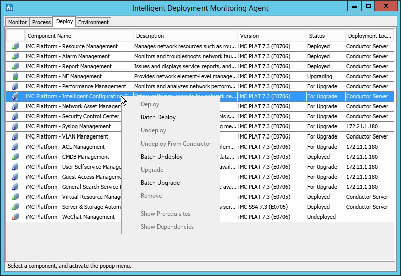
15. Select components to be upgraded, and then click OK.
The system upgrades the components. After the upgrade is complete, the upgrade result page opens.
16. Click OK.
17. On the conductor server, click Start on the Monitor tab of the Intelligent Deployment Monitoring Agent to start IMC.
Restoring IMC
If the IMC upgrade fails, restore IMC to the version before the upgrade:
1. Manually restore the IMC database. For more information, see manual restoration described in "Backing up and restoring the database."
2. After the database restoration is complete, stop IMC in the Intelligent Deployment Monitoring Agent.
3. Close the Intelligent Deployment Monitoring Agent.
4. Stop the Intelligent Management Server service in the server manager.
5. In the IMC installation directory, back up the log files necessary for upgrade failure analysis, and then delete all the files in the directory.
6. Copy the backup IMC installation directory to the IMC installation path.
7. Start the Intelligent Management Server service in the server manager.
8. Start IMC in the Intelligent Deployment Monitoring Agent.
For IMC running in stateful failover mode, restore IMC only on the primary server in the failover system.
Uninstalling IMC
Uninstall IMC component by component or uninstall all components at one time.
To reinstall IMC, complete the following tasks before the reinstallation:
· If you have reinstalled the database after IMC is uninstalled, manually delete the folder that stores data files of the previous IMC system. The default folder is imcdata.
· If IMC installation or uninstallation interrupts with an error, manually delete the IMC installation directory and the iMC-Reserved folder. The iMC-Reserved folder is located in the WINDOWS directory or the Linux etc directory.
Uninstalling an IMC component
Before uninstalling an IMC component, uninstall all components that depend on it.
If you forcibly execute component uninstallation on a member server (for example, an irregular component uninstallation), or if a member server goes down during the component uninstallation process, the deployment information of the uninstalled component cannot be automatically cleared from the conductor server. In this case, you can clear the deployment information of this component on the conductor server by selecting the component on the Deploy tab of the intelligent deployment monitoring agent and select Undeploy From Conductor.
To uninstall an IMC component:
1. Open the Intelligent Deployment Monitoring Agent.
2. On the Monitor tab, click Stop.
3. On the Deploy tab, right-click the component to be uninstalled, and then select Undeploy.
A confirmation dialog box opens.
4. Click Yes.
The Intelligent Deployment Monitoring Agent undeploys the component. After the undeployment is complete, an operation success dialog box opens.
5. Click OK.
6. On the Deploy tab, right-click the undeployed component and select Remove.
A confirmation dialog box opens.
7. Click Yes.
The Intelligent Deployment Monitoring Agent uninstalls the component. After the uninstallation is complete, an operation success dialog box opens.
8. Click OK.
Uninstalling all IMC components at one time
Uninstall the components deployed on member servers first, and then uninstall the components deployed on the conductor server.
Uninstalling IMC components from each member server
1. Open the Intelligent Deployment Monitoring Agent.
2. On the Monitor tab, click Stop.
3. On Windows, click Start, access the all applications page, and then select iMC > Uninstall.
On Linux, run the uninstall.sh script in the /deploy directory of the IMC installation path.
An uninstall wizard opens.
4. Click Uninstall.
5. Click Yes in the confirmation dialog boxes that open.
The Intelligent Deployment Monitoring Agent uninstalls all components. After the uninstallation is complete, the Uninstallation Completed dialog box opens.
6. Clear the OS reboot option and click OK.
7. Delete the iMC-Reserved folder in the WINDOWS folder or the Linux /etc directory.
8. Reboot the operating system.
Uninstalling IMC components from the conductor server
1. Start the Intelligent Deployment Monitoring Agent.
2. On the Monitor tab, click Stop.
3. On Windows, click Start, access the all applications page, and then select iMC > Uninstall.
On Linux, run the uninstall.sh script in the /deploy directory of the IMC installation path.
An uninstall wizard opens.
4. Click Uninstall.
A confirmation dialog box opens.
5. Click Yes.
The Intelligent Deployment Monitoring Agent uninstalls all components. After the uninstallation is complete, the Uninstallation Completed dialog box opens.
6. Clear the OS reboot option and click OK.
7. Delete the iMC-Reserved folder in the WINDOWS folder or in the Linux /etc directory.
8. Reboot the operating system.
Registering IMC
An unregistered IMC version delivers the same functions as those of a registered version, but can be used only for 45 days since the date the service was first started. Register IMC to unlock the time limitation.
For more information about requesting and installing the IMC licenses, see H3C Intelligent Management Center Licensing Guide.
Security settings
Port settings
As a best practice, use a firewall to protect the IMC server cluster by filtering the non-service data sent to the cluster.
|
|
NOTE: · Do not use a switch to filter data packets by using ACLs, because the switch might filter out packet fragmentations. · NTA/UBA typically uses probes for log collection. When a firewall is deployed between the probes and IMC, configure ACLs on the firewall to allow IP packets sent by the probes to IMC. · If you use a software firewall on the conductor or member IMC server, configure the firewall to allow the following ports and also allow the IP address of the member or conductor server to ensure normal communication between the conductor and member servers. |
Make sure the ports used by IMC are not used by other services. For the ports used by the IMC platform and the NTA/UBA components, see Table 18 and Table 19. For the ports used by other components, see the release notes.
Table 18 Port numbers used by the IMC platform
|
Default port number |
Usage |
Location |
|
UDP 161 |
Port to add a device to the IMC |
Device |
|
UDP 22 |
Port for SSH operations |
Device |
|
TCP 23 |
Port for Telnet operations |
Device |
|
UDP 514, 515 |
Port for syslog operations |
IMC server |
|
UDP 162 |
Port for trap operations |
IMC server |
|
TCP 8080, configurable |
HTTP access to IMC |
IMC server |
|
TCP 8443, configurable |
HTTPS access to IMC |
IMC server |
|
UDP 69 |
Port for Intelligent Configuration Center to perform configuration management through TFTP |
IMC server |
|
TCP 20, 21 |
Port for Intelligent Configuration Center to perform configuration management through FTP |
IMC server |
|
TCP 2810 |
Port for data file backup and restoration by using DBMan |
IMC server |
Table 19 Port numbers used by the IMC NTA/UBA
|
Default port number |
Usage |
Location |
|
UDP 9020, 9021, 6343 |
Port for the IMC server to receive logs |
IMC server |
|
TCP 8051 |
Listening port used to monitor the command for stopping the NTA/UBA service |
IMC server |
|
TCP 9099 |
JMX listening port for the NTA/UBA service |
IMC server |
|
UDP 18801, 18802, 18803 |
Communication ports between NTA and UBA |
IMC server |
Backing up and restoring the database
About DBMan
DBMan is the automatic backup and restoration tool for the IMC platform and service component databases, and provides a full-range system disaster backup solution. DBMan uses a standard SQL backup and restoration mechanism to process the complete databases.
DBMan supports both manual and automatic database backup and restoration. It is integrated in the Environment tab of the Intelligent Deployment Monitoring Agent, as shown in Figure 93 and Figure 94.
Figure 93 Environment tab (local database)
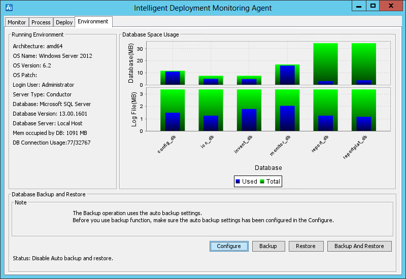
Figure 94 Environment tab (remote database)

The Environment tab includes the following areas:
· Running Environment—Displays the software and hardware information on the IMC server.
· Database Space Usage—Displays the database and log file usage information of each component on the IMC server.
· Database Backup and Restore—Provides the following database backup and restoration options:
¡ Configure—Allows you to configure automatic database backup and restoration settings. The automatic backup and restoration function is typically used in stateless failover scenarios.
¡ Backup—Immediately backs up all IMC data files (including configuration files and database files) to a specified path.
¡ Restore—Immediately restores previously backed up database files on the IMC server.
¡ Backup And Restore—Immediately backs up the database on the primary server to the backup server and performs automatic restoration. This option is applicable to stateless failover scenarios.
Starting DBMan on the database server (for remote databases only)
Installing DBMan on the database server
By default, DBMan is not installed on the remote database server. Before database backup and restoration, install DBMan on the database server.
DBMan can be installed automatically on the database server when you install the Intelligent Deployment Monitoring Agent.
To start the remote installation wizard for installing the Intelligent Deployment Monitoring Agent, see "Starting the remote installation wizard."
To install the Intelligent Deployment Monitoring Agent after the wizard has been started, see "Installing the Intelligent Deployment Monitoring Agent."
After installation, DBMan will be started when you start the server.
Upgrading DBMan
When you upgrade IMC, the Upgrade Common Component dialog box opens, as shown in Figure 95. Click Yes to upgrade common components including DBMan.
Figure 95 Upgrade Common Component
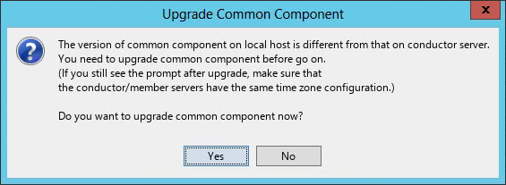
Backing up and restoring databases for a single IMC system
Backing up databases
A single IMC system supports both manual and automatic backup:
· Manual backup—Immediately backs up all IMC data files to the specified location on the conductor IMC server.
· Automatic backup—Allows you to schedule a task to automatically back up selected data files on the conductor and member database servers locally or to the conductor server at the specified time.
Manual backup
1. Start the Intelligent Deployment Monitoring Agent on the conductor IMC server, as shown in Figure 93 and Figure 94.
2. On the Environment tab, click Backup.
A confirmation dialog box opens.
3. Click Yes.
The Select database backup path dialog box opens.
4. Specify a local path to save the backed up data files.
Make sure the specified path has enough space.
5. Click OK to back up data files on all IMC servers to the specified path on the conductor server.
Automatic backup
1. Start the Intelligent Deployment Monitoring Agent on the conductor IMC server, as shown in Figure 93 and Figure 94.
2. On the Environment tab, click Configure.
3. In the confirmation dialog box regarding the installation and operation of DBMan that opens, click OK.
The Auto Backup and Restore Settings dialog box opens, as shown in Figure 96.
Figure 96 Auto Backup and Restore Settings
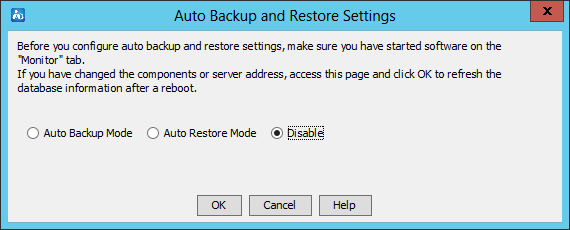
4. Read information in the Auto Backup and Restore Settings dialog box, select Auto Backup Mode, and then click OK.
The page for configuring automatic backup settings opens, as shown in Figure 97 and Figure 98. The Basic Configuration area provides the Conductor Server tab and the Member Server tab.
Figure 97 Configuring automatic backup settings (local database)
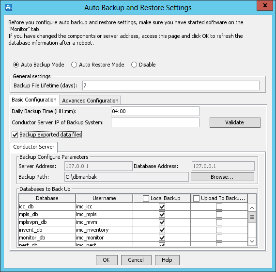
Figure 98 Configuring auto backup settings (remote database)
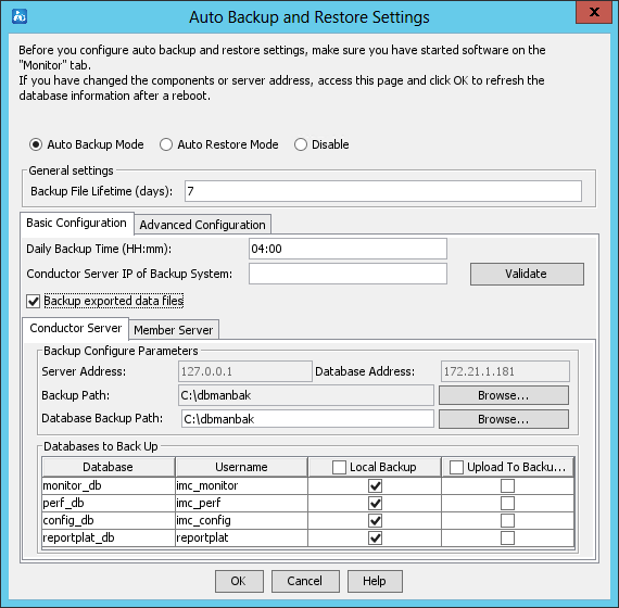
5. In the General settings area, configure the Backup File Lifetime (days) parameter:
¡ Backup File Lifetime (days)—Enter how many days a backup file can be kept. Expired files are automatically deleted. By default, the backup file lifetime is 7 days.
6. Click the Basic Configuration tab, and then configure the following parameters:
¡ Daily Backup Time (HH:mm)—Enter the time at which the automatic backup operation starts every day. By default, the daily backup time is 04:00.
¡ Conductor Server IP of Backup System—This parameter is applicable to database backup in stateless failover scenarios. To upload the database files to the conductor server of the backup system, specify the conductor server IP address in this field. Make sure automatic restoration is enabled for the backup system. To verify the component and version consistency between the primary IMC system and the backup IMC system, click Validate.
¡ Backup exported data files—Select this parameter to back up exported data files.
7. Click the Conductor Server tab, and then configure the following parameters:
¡ Backup Path—Enter or browse to a local path on the conductor IMC server to store the backup data files.
¡ Database Backup Path—Enter or browse to a local path on the database server to store the backup database files from the conductor IMC server in remote database deployment mode.
¡ Local Backup—Select the databases on the conductor IMC server to back up locally. By default, all databases are selected.
¡ Upload To Backup System—Select the databases on the conductor IMC server to be uploaded to an FTP server or the conductor server of a backup system. By default, no database is selected. When you select Upload To Backup System for a database, the Local Backup option is forcibly selected for the database. To configure the FTP server, see "Configuration restrictions and guidelines."
8. Click the Member Server tab, and then configure the following parameters:
¡ Backup Path—Enter or browse to a local path on the member IMC server to store the backup data files.
¡ Database Backup Path—Enter or browse to a local path on the database server to store the backup database files from the member IMC server in remote database deployment mode.
¡ Local Backup—Select the databases on the member IMC server to back up locally. By default, all databases are selected.
¡ Upload To Backup System—Select the databases on the member IMC server to be uploaded to an FTP server or the conductor server of a backup system. By default, no database is selected. When you select Upload To Backup System for a database, the Local Backup option is forcibly selected for the database. To configure the FTP server, see "Configuration restrictions and guidelines."
9. Click the Advanced Configuration tab, and then configure the following parameters:
¡ Delete local files after upload even if upload fails—Specify whether to delete local backup files after they are uploaded.
¡ Transfer backup files of member servers to the conductor server—In automatic backup mode, the backup files on the member server are saved on the member server by default. Select this option to upload the backup files from the member server to the conductor server. (This option is only available in distributed deployment mode.)
10. Click OK.
Restoring databases
A single IMC system supports only manual restoration of the databases.
In local database deployment mode, manual restoration immediately replaces all database files with the backup database files.
In remote database deployment mode, manual restoration immediately replaces all database files with the backup database files. It supports the following types:
· Locally Restore—Applicable to scenarios where all backup files are saved on the conductor server.
· Remotely Restore—Applicable to scenarios where backup files are saved on the database server.
As a best practice, restore database files for the IMC platform and service components together. If you restore only some of the database files, data loss or inconsistency might occur.
Make sure IMC has been started at least once after installation before you restore the IMC databases.
To perform a manual restoration:
1. On the Environment tab, click Restore.
The Restoration Type dialog box opens, as shown in Figure 99.
Figure 99 Restoration Type dialog box
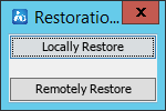
2. If all backup files are saved on the conductor server, perform the following tasks:
a. Click Locally Restore.
The Confirm dialog box opens, as shown in Figure 100.
Figure 100 Confirming the operation
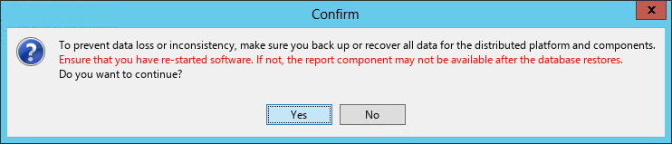
b. Click Yes.
The Select the data file to be restored dialog box opens.
c. Select database files to be restored, and then click OK.
A confirmation dialog box opens.
Figure 101 Confirmation dialog box

d. Click Yes.
The system starts restoring the database files.
After the local restoration is complete, the system displays a restoration success message.
3. If local backup data files are saved on both the conductor and member servers or the backup data files are saved on the database servers, perform the following tasks:
a. Click Remotely Restore.
The Configure Remote Restoration dialog box opens.
Figure 102 Configure Remote Restoration dialog box (local database)
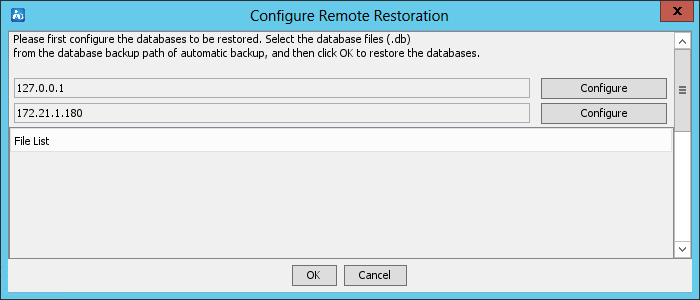
Figure 103 Configure Remote Restoration dialog box (remote database)

b. Click Configure.
- In local database deployment mode, select the database files to be restored on the conductor and member servers.
- In remote database deployment mode, select the database files to be restored on the database servers associated with the conductor and member servers.
c. Click OK.
A confirmation dialog box opens.
Figure 104 Confirmation dialog box

d. Click Yes.
The system starts restoring the database files.
After the remote restoration is complete, the system displays a restoration success message.
4. Click OK.
The IMC service will be automatically started.
|
|
NOTE: · Before remote restoration, you must configure automatic backup and restoration parameters. Then DBMan can automatically locate running configuration files and database files. · During the restoration process, DBMan shuts down and restarts IMC and the database service. |
Backing up and restoring databases in stateless failover scenarios
A typical stateless failover scenario includes a primary IMC system and a backup IMC system.
In stateless failover of IMC systems using centralized deployment with local or remote databases, a typical scenario is as follows:
· The primary IMC system uses centralized deployment with remote databases.
· The backup IMC system can be deployed in any mode.
In stateless failover of IMC systems using distributed deployment with local or remote databases, the typical scenarios include:
· Local database—The primary IMC system uses distributed deployment with local databases, and the backup IMC system can be deployed in any mode.
· Remote database—The primary IMC system uses distributed deployment with remote databases, and the backup IMC system can be deployed in any mode.
In these stateless failover scenarios, configure automatic backup on the primary IMC system and configure automatic restoration on the backup IMC system.
During automatic backup and restoration, DBMan of the primary IMC system performs the following operations:
1. Periodically or immediately backs up database files locally.
2. Uploads the backed up database files to the backup IMC system.
3. Instructs the backup IMC system to restore the received database files locally.
Backing up databases
In stateless failover, configure automatic backup on the conductor server of the primary IMC system.
Before the configuration, make sure the following settings are consistent on the primary and backup IMC systems:
· OS
· Database type and version
· IMC version and patches
For more information about how to configure automatic backup, see "Automatic backup."
Restoring databases
In a stateless failover scenario, you can configure automatic restoration on the backup IMC system. After receiving the backed up database files from the primary IMC system, the backup IMC system automatically restores the database files locally.
· Centralized scheme—Configure automatic restoration for the backup IMC system of stateless failover. This feature works with the automatic backup feature of the primary IMC system to keep the data synchronized between the backup and primary IMC systems. For the automatic backup feature on the primary IMC system, configure the conductor server IP of the backup IMC system and select to upload component data. By obtaining the backup IMC system's configuration files, the primary IMC system obtains the automatic restoration configuration. After the primary IMC system completes automatic backup, it immediately transfers the backup data to the restoration path set in the backup IMC system. Also, the primary IMC system instructs the backup IMC system to execute automatic restoration.
· Distributed scheme—Use automatic restoration for the databases in stateless failover. After the primary IMC system completes automatic backup, it immediately transfers the backup data to the backup IMC system's automatic restoration path and instructs the backup IMC system to perform automatic restoration, ensuring database synchronization.
This example describes the automatic restoration settings on a backup IMC system that is deployed in distributed mode and uses a local or remote database.
To configure automatic restoration:
1. Start the Intelligent Deployment Monitoring Agent on the conductor server of the backup IMC system.
2. On the Environment tab, click Configure.
3. In the confirmation dialog box regarding the installation and operation of DBMan that opens, click OK.
The Auto Backup and Restore Settings dialog box opens, as shown in Figure 105.
Figure 105 Auto Backup and Restore Settings dialog box

4. Read information in the Auto Backup and Restore Settings dialog box, select Auto Restore Mode, and then click OK.
The page for configuring auto restoration settings opens, as shown in Figure 106 and Figure 107. The automatic restoration configuration provides two tabs: Conductor Server and Member Server.
Figure 106 Configuring auto restoration settings (local database)
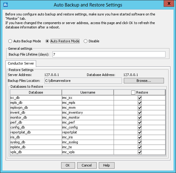
Figure 107 Configuring auto restoration settings (remote database)

5. Click the Conductor Server tab, and configure the following parameters:
¡ Backup Files Location—Enter or browse to a local path on the backup system that stores the backup data files uploaded by the conductor server of the primary IMC system.
¡ Backup Files Location of Database—Enter or browse to a local path on the backup system that stores the backup database files uploaded by the conductor server of the primary IMC system.
¡ Restore—Select databases to be restored. By default, all databases are selected. You can select or deselect all options.
6. Click the Member Server tab, and configure the following parameters:
¡ Backup Files Location—Enter or browse to a local path on the backup system that stores the backup data files uploaded by the member server of the primary IMC system.
¡ Backup Files Location of Database—Enter or browse to a local path on the backup system that stores the backup database files uploaded by the member server of the primary IMC system.
¡ Restore—Select databases to be restored. By default, all databases are selected. You can select or deselect all options.
7. Click OK.
Backing up and restoring databases
In a stateless failover scenario, use this option to back up the database on the primary IMC system to the backup IMC system and configure automatic restoration on the backup IMC system.
To configure backup and restoration:
1. Configure automatic backup on the primary IMC system in the same way you configure database backup in a single IMC system. For more information, see "Automatic backup."
2. Configure automatic restoration on the backup IMC system. For more information, see "Automatic backup."
3. Click Backup and Restore on the Environment tab in the Intelligent Deployment Monitoring Agent, as shown in Figure 108 and Figure 109.
Figure 108 Configuring backup and restoration (local database)
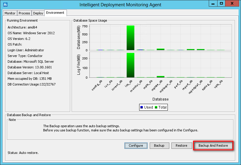
Figure 109 Configuring backup and restoration (remote database)

Configuration restrictions and guidelines
To ensure correct operation, do not back up and restore IMC databases between different operating systems.
When you use DBMan to back up and restore IMC databases, follow these restrictions and guidelines:
· In automatic backup configuration, use the Upload to Backup System option to back up database files to a backup IMC system or an FTP server.
· The Upload to Backup System option requires one of the following conditions:
¡ The Conductor Server IP of Backup System is specified for database backup.
¡ An FTP server is configured in the dbman_ftp.conf file in the \dbman\etc directory of the IMC installation path. For example:
ftp_ip=1.1.1.1
ftp_user=admin
ftp_password=1234
· To add additional backup and restoration settings, edit the dbman_addons.conf file in the \dbman\etc directory of the IMC installation path. The settings take effect immediately after the file is saved.
For example, add the following strings to the dbman_addons.conf file to specify tasks to perform before or after database restoration:
BeforeSQLScript_monitor_db_IMC_monitor = D:\1.bat
AfterSQLScript_monitor_db_IMC_monitor = D:\2.bat
· After Oracle database restoration is complete, make sure the tablespace name is the same as that before restoration.
FAQ
After IMC installation is complete, how do I change the database file storage path?
1. Stop the IMC service by using the Intelligent Deployment Monitoring Agent.
2. Transfer the databases of IMC components to the new storage path on the database server. This example uses D:\imcdata.
3. At the CLI, access the \deploy directory of the IMC installation path, and then modify the database file storage path.
pwdmgr.bat –changeDataDir "D:\imcdata"
Figure 110 shows that the storage path has been successfully modified.
Figure 110 Modifying the database file storage path

4. Start the IMC service.
When IMC is deployed in distributed mode, how can I deploy, upgrade, or undeploy components on the conductor server without shutting down the service processes on the member server?
Open the dma.conf file in the IMC installation directory\deploy\conf directory on the member IMC server and add the "synstop=false" line to keep processes on the member server running when the conductor IMC server stops.
In Linux, the time on the server (such as the login time and operation log record time) is different from the time on the server, and the difference might be several hours.
This issue occurs because the current time zone setting on the server is different from that when IMC was installed. Use the tzselect command to modify the time zone of the server.
How can I solve the issue that the backend IMC processes fail to start after IMC is installed on a Windows Server 2003 64-bit operating system?
Before installing IMC on a Windows Server 2003 64-bit operating system, you must install the WindowsServer2003-KB942288-v4-x64.exe patch. If you do not do that, some IMC processes will fail to start after installation.
If this issue has occurred, perform the following tasks to resolve this issue:
1. Stop IMC.
2. Install the preceding patch.
3. Manually execute the vcredist.exe file in the IMC installation path\deploy\components\server\ directory.
During the component deployment process, a deployment failure occurs and the system displays a database script execution error message. The log file includes an error message that the object dbo.qv.id already exists. How do I resolve the issue?
1. Log in to the Query Analyzer of SQL Server as sa, and then execute the following commands:
use model
EXEC sp_droptype 'qv_id'
2. Redeploy the component that failed to be deployed.
When I install IMC on Windows Server 2008 R2, a prompt message appears indicating that Windows Installer cannot install the package, as shown in Figure 111. How can I resolve this issue?
Figure 111 Window Installer window
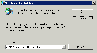
To resolve this issue:
2. In the Windows Installer window that opens, click Browse….
3. On the file selection page, find the folder named with digits and the six letters abcdef in the root directory of the disk.
4. Select vc_red.msi in this folder, and click OK to proceed with the installation process.
In Linux, how do I start JavaService when Xwindows is closed?
Use the service IMCdmsd start command to start the JavaService.
In Windows, IMC service processes cannot be started or stopped after IMC runs for a period of time.
This issue is caused by insufficient virtual memory.
To resolve this issue, set the virtual memory to the system managed size:
1. On the IMC server, click Control Panel, and then click the System icon.
The System Properties dialog box opens, as shown in Figure 112.
Figure 112 System Properties dialog box
2. Click the Advanced tab, and then click Settings in the Performance area.
The Performance Options dialog box opens, as shown in Figure 113.
Figure 113 Performance Options dialog box

3. Click the Advanced tab, and then click Change in the Virtual memory area.
The Virtual Memory dialog box opens, as shown in Figure 114.
Figure 114 Virtual Memory dialog box
4. Select System managed size, and then click Set.
5. Click OK.
In Linux, popup windows cannot be found during IMC deployment or upgrade.
When Xshell or Xstart is used for remote GUI access on Linux, a window might open on top of popup windows. To resolve this issue, move the window away to view the popup windows.
While I am installing .Net Framework 2.0 SP2 on a Windows server, the system displays an error message that the source file of .Net Framework 2.0 SP2 cannot be found. How can I resolve this issue?
To resolve this issue, add the source file of .Net Framework 2.0 SP2 to the Windows server:
1. Insert the Windows Server installation disk to the drive, and then locate the installation files of .Net Framework 3.5 in the disk.
In this example, the files are located in directory D:\sources\sxs, as shown in Figure 115.
Figure 115 Locating the installation files of .Net Framework 3.5
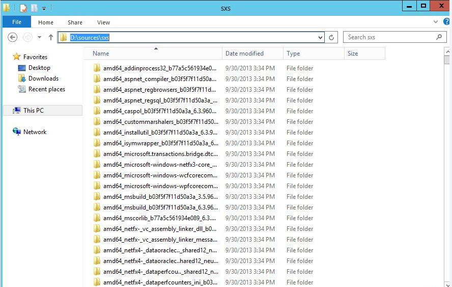
2. On the Confirm installation selections page of the Add Roles and Features Wizard shown in Figure 116, click Specify an alternate source path.
Figure 116 Confirm installation selections page
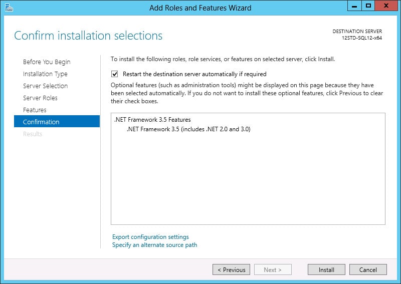
3. On the Specify an alternate source path page shown in Figure 117, enter the directory where the installation files of .Net Framework 3.5 are located in the Path field. This example uses D:\sources\sxs. Click OK.
Figure 117 Specify an alternate source path page
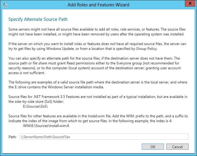
4. On the Confirm installation selections page, click Install to start installing .Net Framework 3.5.
After the installation is complete, click Close.
License verification fails after the Windows operating system reboots. How can I resolve this issue?
The license file contains only one MAC address if the license is requested after NIC teaming. After the operating system reboots, license verification fails because the MAC address of the NIC team has changed.
To resolve this issue, assign a static MAC address to the NIC team, as shown in Figure 118.
Figure 118 Assigning a static MAC address to the NIC team
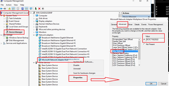
On RHEL 8 or CentOS 8 or a later version, embedded database installation for IMC PLAT 7.3 (E0706) is interrupted. A message "mysql: error while loading shared libraries: libtinfo.so.5: cannot open shared object file: No such file or directory" is displayed. How can I resolve this issue?
To resolve this issue, execute the following command to install the ncurses-compat-libs-6.1-7.20180224.el8.x86_64.rpm dependency before installing IMC:
rpm –ivh ncurses-compat-libs-6.1-7.20180224.el8.x86_64.rpm
Figure 119 Installing the dependency