- Released At: 30-05-2023
- Page Views:
- Downloads:
- Table of Contents
- Related Documents
-
|
|
|
Intelligent Management Center |
|
WSM WLAN Configuration Examples |
|
|
Document version: 5W100-20230529
Software version: IMC WSM 7.3 (E0505)
|
Copyright © 2023 New H3C Technologies Co., Ltd. All rights reserved. No part of this manual may be reproduced or transmitted in any form or by any means without prior written consent of New H3C Technologies Co., Ltd. The information in this document is subject to change without notice. |
|
Content
Example: Configuring a WLAN (H3C)
Example: Configuring a WLAN (HP)
Example: Configuring a WLAN mesh network
Introduction
This document provides WSM configuration examples.
Wireless Service Manager (WSM), together with Intelligent Management Center (IMC) and Intelligent Control Configuration (ICC), provides a sophisticated way for WLAN management. IMC is responsible for universal network management, ICC for configuration file management and software upgrade, and WSM for device-related wireless parameter configuration and performance monitoring.
Prerequisites
Before the configuration, verify the following items:
· The IMC PLAT version is 7.3 (E0504) and above, and the IMC WSM version is 7.3 (E0505) and above.
· The browser version is:
¡ IE10 or IE11.
¡ Firefox 30 and above.
¡ Chrome 35 and above.
· The access device is a wireless device.
· IMC service has been enabled.
· You log in as a user that has the configuration privilege, for example, an administrator.
Example: Configuring a WLAN (H3C)
Network configuration
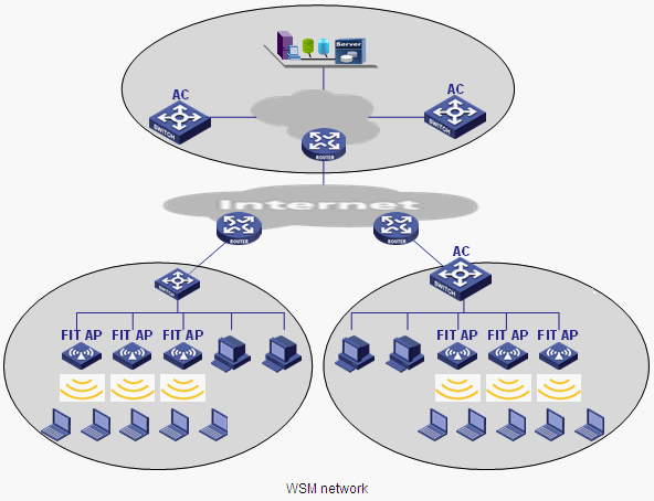
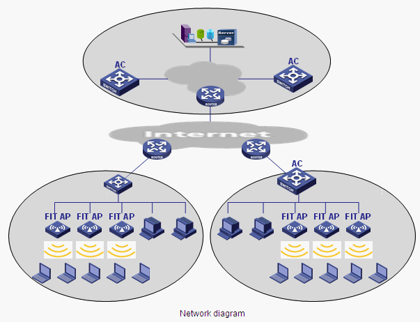
As shown in Figure 1, build a wireless internal network to connect the headquarters and its three branch offices in a cost-effective way.
To achieve this purpose:
· Use the AC + fit AP networking mode.
· Deploy the AC at the enterprise backbone network, the carrier MAN, or the entrance of hotspots such as branch offices.
· Deploy fit APs at the lower layer of the AC in branch offices.
· Deploy WSM components at the enterprise backbone network or the carrier MAN to uniformly manage wired and wireless networks.
Procedures
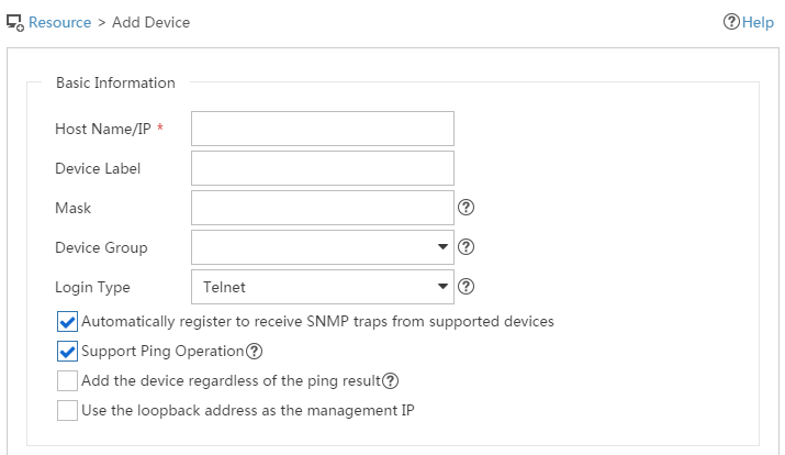
1. Add wireless devices:
Click the Resource tab, and click Add Device or Auto Discovery, as shown in Figure 2.
Figure 2 Adding wireless devices
2. Configure the AC:
a. Click the Resource tab, and click Wireless icon on the page that appears.
Or click the Service tab, and select WLAN Manager > Resource Management > ACs from the navigation tree.
b. Click the device label for the target device. The Device Information page appears, as shown in Figure 3.
Figure 3 Device information
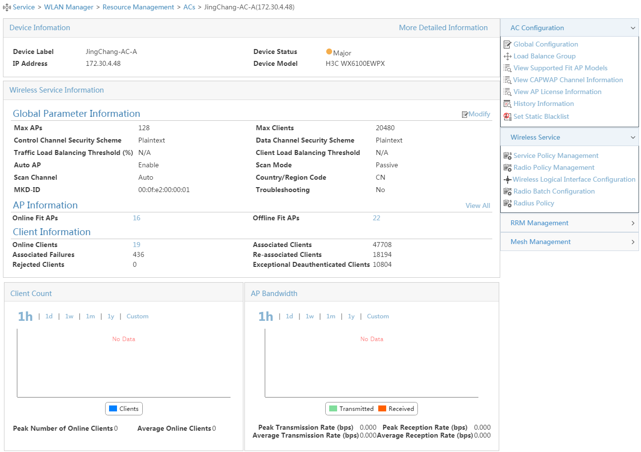
c. In the Wireless Service Information area, click Modify. The AC Global Parameter Configuration page appears, as shown in Figure 4.
Figure 4 Configuring AC global parameters
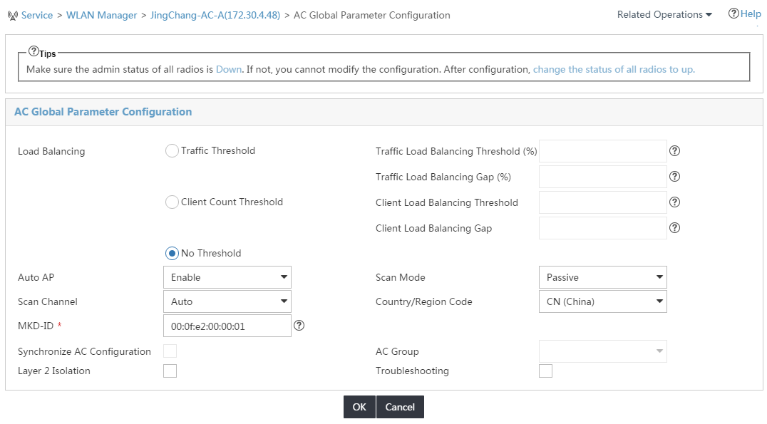
d. Select CN(China) from the Country/Region Code list. Configure the traffic load balancing threshold if you select the traffic load balancing mode, or configure the client load balancing threshold if you select the client load balancing mode, and click OK.
3. Add a fit AP template for the AC:
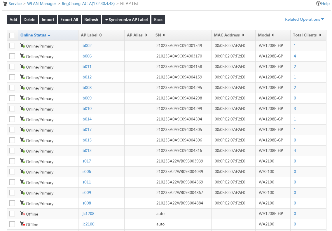
a. Enter the Fit AP List page.
- Enter the Device Information page of the AC as previously shown in Figure 3. In the Wireless Service Information area, click View All.
- Or click the Service tab, select WLAN Manager > Resource Management > ACs from the navigation tree, click the operation icon for the target AC, and select Fit AP List from the menu that appears, as shown in Figure 5.
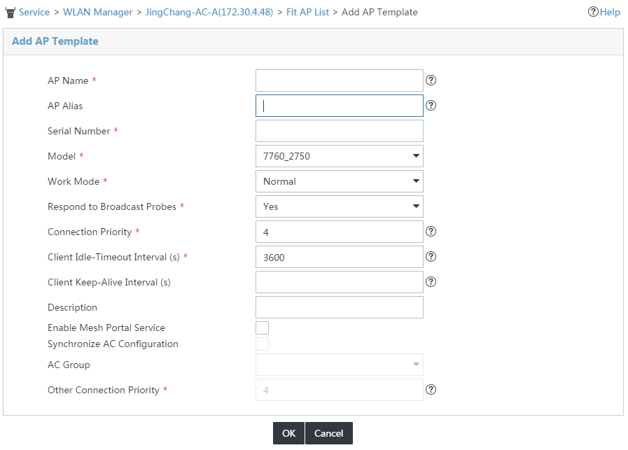
b. Click Add or Import to add a fit AP template.
c. Configure the AP name, serial number, model, and other information as required, and click OK, as shown in Figure 6.
Enter the actual serial number of the AP or set it to Auto.
Figure 6 Adding an AP template
4. Add a service policy for the AC:
a. Enter the Service Policy Management page.
- Enter the Device Information page of the AC as shown in Figure 3, and click Service Policy Management in the Wireless Service area on the right of the page.
- Or click the Service tab, select WLAN Manager > Resource Management > ACs from the navigation tree, click the operation icon for the target AC, and select Service Policy from the menu that appears, as shown in Figure 7.
Figure 7 Managing service policies
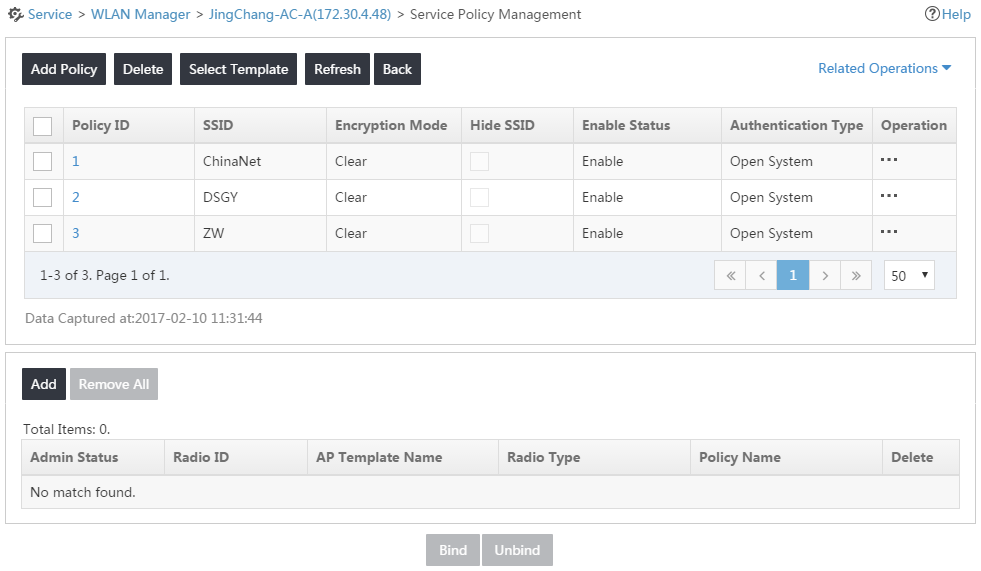
b. Click Add Policy. The Add Service Policy page appears, as shown in Figure 8.
Figure 8 Adding a service policy
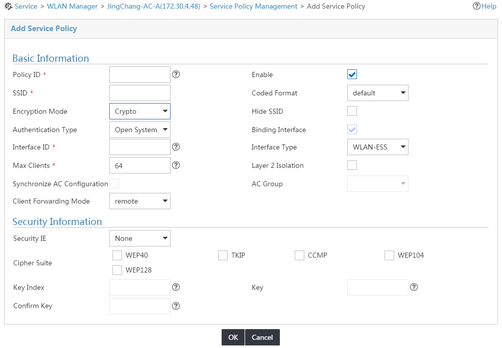
c. Set the policy ID, SSID, interface ID, authentication type, and other information as required, and click OK.
5. Add a radio policy for the AC:
a. Enter the Radio Policy Management page.
- Enter the Device Information page of the AC as shown in Figure 3, and click Radio Policy Management in the Wireless Service area on the right of the page.
- Or click the Service tab, select WLAN Manager > Resource Management > ACs from the navigation tree, click the operation icon for the target AC, and select Radio Policy from the menu that appears, as shown in Figure 9.
Figure 9 Managing radio policies
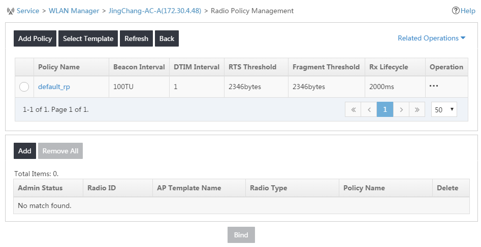
b. Click Add Policy. The Add Radio Policy page appears, as shown in Figure 10.
Figure 10 Adding a radio policy
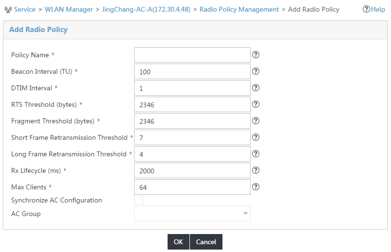
c. Set the policy name, DTIM interval, RTS threshold, and other information as required, and click OK.
6. Configure radio parameters for the fit AP:
a. View detailed information about the specified AP.
- Enter the Device Information page of the AC as shown in Figure 3. In the Wireless Service Information area, click View All.
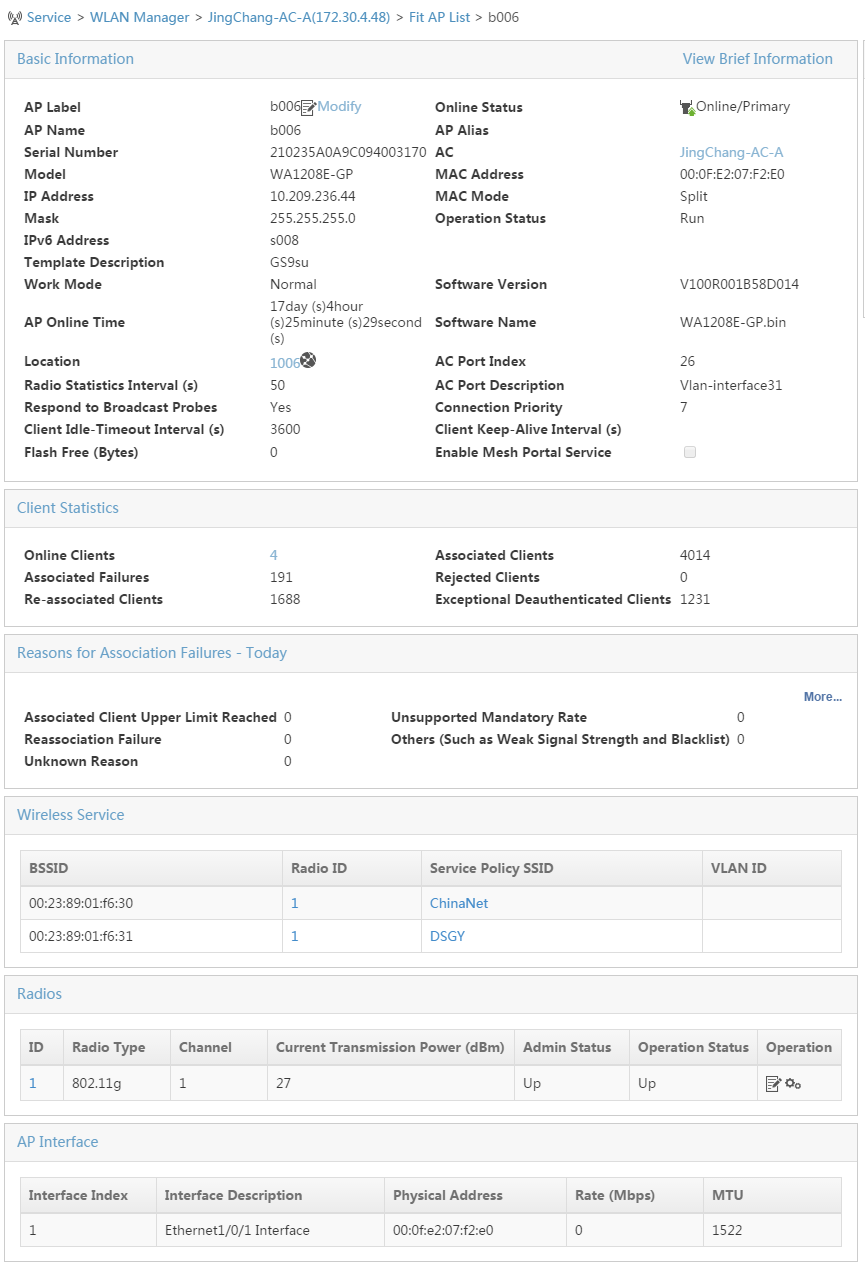
- Or click the Service tab, select WLAN Manager > Resource Management > ACs from the navigation tree, click the operation icon for the target AC, and select Fit AP List from the menu that appears. Click More Detailed Information at the top right corner to view detailed AP information, as shown in Figure 11.
Figure 11 Detailed information of a fit AP
b. Click the modification icon for the target radio. The Modify Radio Parameters page appears, as shown in Figure 12.
Figure 12 Modifying radio parameters
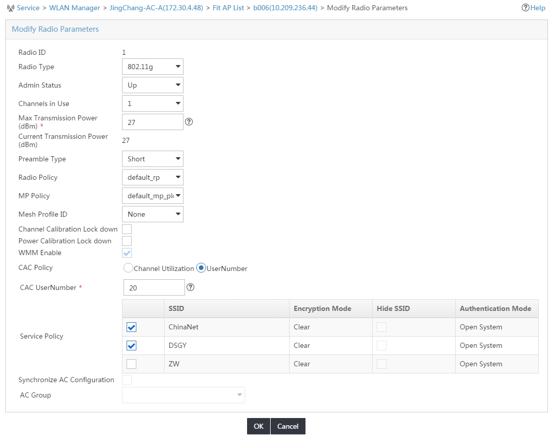
c. Select UP from the Admin Status list, select a proper radio policy from the Radio Policy list, and select at least one service policy, and click OK.
Verifying the configuration
Open the Network Connections window on a wireless terminal, click Wireless Network Connection, and click Refresh Network List. You can find the SSID configured in this example on the list of wireless networks.
Example: Configuring a WLAN (HP)
Network configuration
As shown in Figure 13, build a wireless internal network to connect the headquarters and its three branch offices in a cost-effective way.
To achieve this purpose:
· Use the AC + fit AP networking mode.
· Deploy the AC at the enterprise backbone network, the carrier MAN, or the entrance of hotspots such as branch offices.
· Deploy fit APs at the lower layer of the AC in branch offices.
· Deploy WSM components at the enterprise backbone network or the carrier MAN to uniformly manage wired and wireless networks.
In this example, an HP MSM Series access controller is used.
Procedures
If the MSM devices are connected through PB, you need to specify the IP address of the management console on the MSM device as the IP address of the server where WSM is installed.
To configure a WLAN (HP):
1. Add MSM wireless devices to the platform:
Click the Resource tab, and click Auto Discovery or Add device to add wireless devices, as shown in Figure 2.
2. Configure the AC:
a. Click the Resource tab, and click Wireless icon on the page that appears.
Or click the Service tab, select WLAN Manager > Resource Management > ACs from the navigation tree.
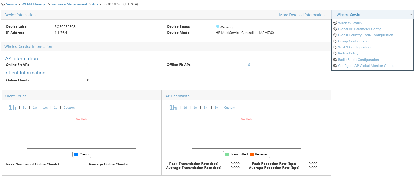
b. Click the device label for the target device. The Device Information page appears, as shown in Figure 14.
Figure 14 Device information
c. Enter the Modify Country/Region Code for The HP AC page, as shown in Figure 15.
- On the page that appears, click Configure AC Global Country/Region Code in the Wireless Service area on the right of the page.
- Or click the Service tab, select WLAN Manager > Resource Management > ACs from the navigation tree, click the operation icon for the target AC, and select Configure AC Global Country/Region Code from the menu that appears.
Figure 15 Modifying country/region code

3. Add an AP group for the AC:
a. Enter the Group Configuration page.
- Enter the Device Information page of the AC as shown in Figure 14, and click Group Configuration in the Wireless Service area on the right of the page.
- Or click the Service tab, select WLAN Manager > Resource Management > ACs from the navigation tree, click the operation icon for the target AC, and select Group Configuration from the menu that appears. The Group Configuration page appears, as shown in Figure 16.
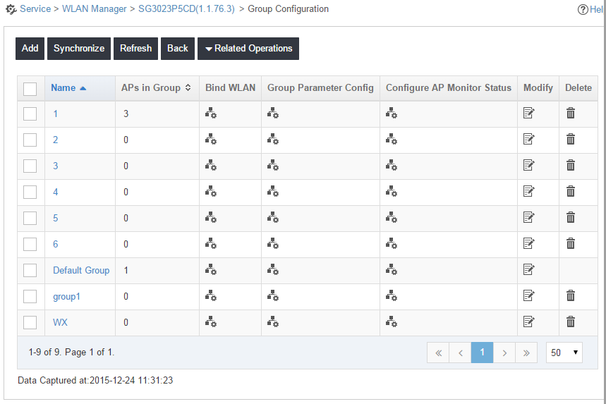
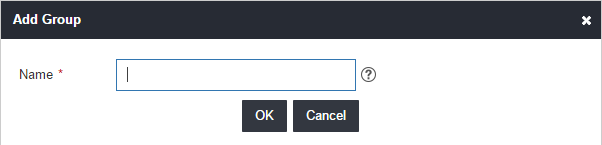
b. Click Add, enter a group name in the window that appears (Figure 17), and click OK.
4. Add a fit AP to the group:
a. Enter the Group Configuration page as shown in Figure 16.
b. Click the name link for the target group. The APs in Group page appears, as shown in Figure 18.
Figure 18 Adding a fit AP to the group
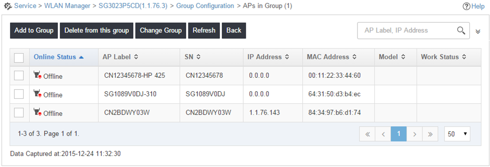
c. Click Add to Group, select the target fit AP from the window that appears, and click OK.
5. Create a WLAN for the AC:
a. Enter the WLAN Configuration page.
- Enter the Device Information page of the AC as shown in Figure 14, and click WLAN Configuration in the Wireless Service area on the right of the page.
- Or click the Service tab, select WLAN Manager > Resource Management > ACs from the navigation tree, click the operation icon for the target AC, and select WLAN Configuration from the menu that appears. The WLAN Configuration page appears, as shown in Figure 19.
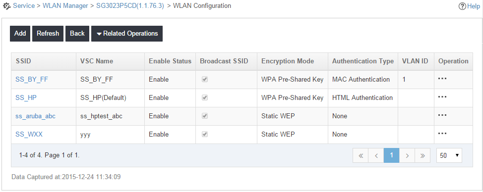
b. Click Add. The Add WLAN page appears, as shown in Figure 20.
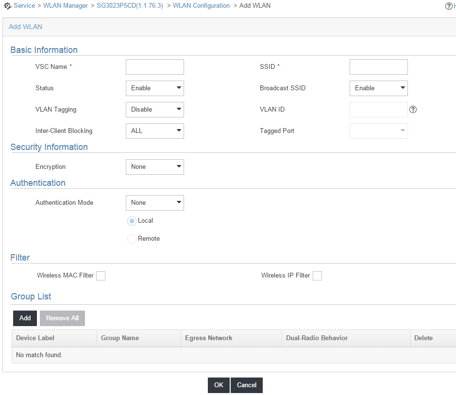
c. Configure the VSC name, SSID, VLAN ID, and other parameters as required, and click OK.
6. Bind a group to the WLAN:
a. Enter the Bound Group List page.
- Enter the Device Information page of the AC as shown in Figure 14, and click WLAN Configuration in the Wireless Service area on the right of the page.
- Or click the Service tab, select WLAN Manager > Resource Management > ACs from the navigation tree, click the operation icon for the target AC, and select WLAN Configuration from the menu that appears.
The page as shown in Figure 19 appears. Click the operation icon for the target WLAN. The Bound Group List page appears, as shown in Figure 21.
Figure 21 Binding a group to the WLAN
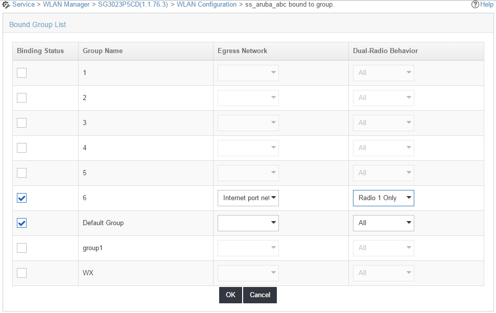
b. Select the group to be bound, select an egress network and the dual-radio behavior for the target group, and click OK.
Verifying the configuration
Open the Network Connections window on a wireless terminal, click Wireless Network Connection, and click Refresh Network List. You can find the SSID configured in this example on the list of wireless networks.
Example: Configuring a WLAN mesh network
Network configuration
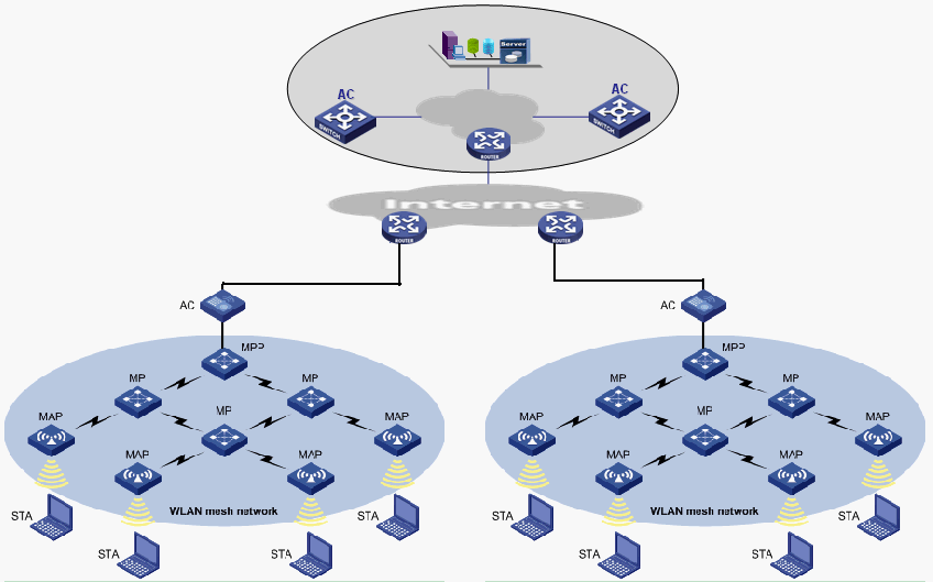
As shown in Figure 22, use the WLAN mesh technology to build a wireless internal network to connect the headquarters and its three branch offices in a cost-effective way.
To achieve this purpose:
· Use the AC + fit AP networking mode.
· Deploy the AC at the enterprise backbone network, the carrier MAN, or the entrance of hotspots such as branch offices.
· Deploy fit APs at the lower layer of the AC in branch offices.
· Deploy WSM components at the enterprise backbone network or the carrier MAN to uniformly manage wired and wireless networks.
Procedures
1. Add wireless devices to the platform:
Click the Resource tab, and click Add Device or Auto Discovery to add wireless devices as shown in Figure 2.
2. Configure the AC:
a. Click the Resource tab, and click Wireless icon on the page that appears.
Or click the Service tab, select WLAN Manager > Resource Management > ACs from the navigation tree.
b. Click the device label for the target device. The Device Information page appears, as shown in Figure 3.
c. In the Wireless Service Information area, click Modify.
d. Select CN(China) from the Country/Region Code list. Configure the traffic load balancing threshold if you select the traffic load balancing mode, or configure the client load balancing threshold if you select the client load balancing mode, and click OK.
3. Add a fit AP template for the AC:
a. Enter the Fit AP List page as shown in Figure 5.
- Enter the Device Information page of the AC as shown in Figure 3. In the Wireless Service Information area, click View All.
- Or click the Service tab, select WLAN Manager > Resource Management > ACs from the navigation tree, click the operation icon for the target AC, and select Fit AP List from the menu that appears.
b. Click Add or Import to add a fit AP template.
c. Configure the AP name, serial number, model and other required information, and click OK. If the AP is an MPP, enable the Mesh Portal.
4. Add an MP policy for the AC:
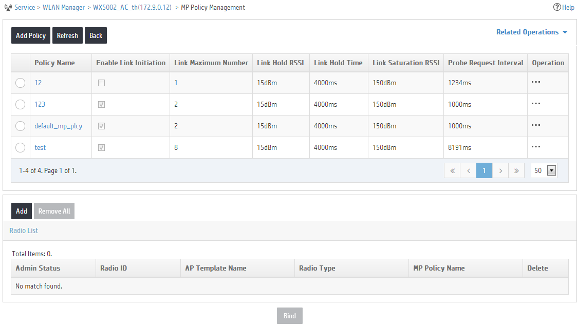
a. Enter the MP Policy Management page.
- Enter the Device Information page of the AC as shown in Figure 3, and click MP Policy Management in the Mesh Management area on the right of the page.
- Or click the Service tab, select WLAN Manager > Resource Management > ACs from the navigation tree, click the operation icon for the target AC, and select MP Policy Management from the menu that appears. The MP Policy Management page appears, as shown in Figure 23.
Figure 23 Managing MP policies
b. Click Add Policy. The Add MP Policy page appears, as shown in Figure 24.
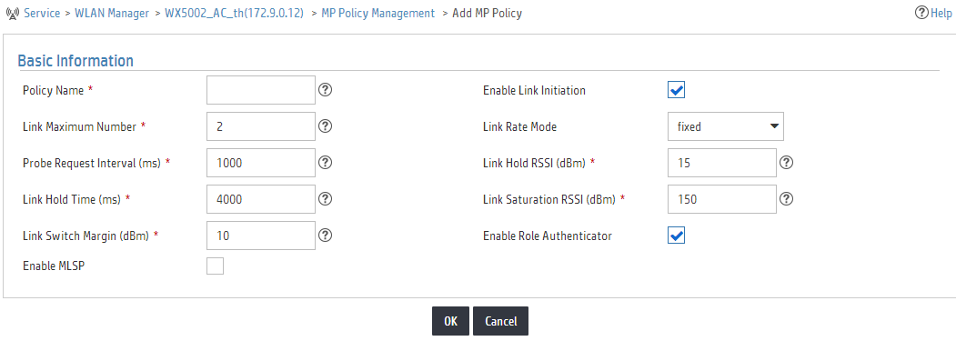
c. Configure the policy name, link maximum number, parameters used to count COST values, and other information as required, select Enable Link Initiation, and click OK.
5. Add a mesh interface for the AC:
a. Enter the Mesh Interface Management page.
- Enter the Device Information page of the AC as shown in Figure 3, and click MP Interface Management in the Mesh Management area on the right of the page.
- Or click the Service tab, select WLAN Manager > Resource Management > ACs from the navigation tree, click the operation icon for the target AC, and select MP Interface Management from the page that appears. The Mesh Interface Management page appears, as shown in Figure 25.
Figure 25 Managing mesh interfaces
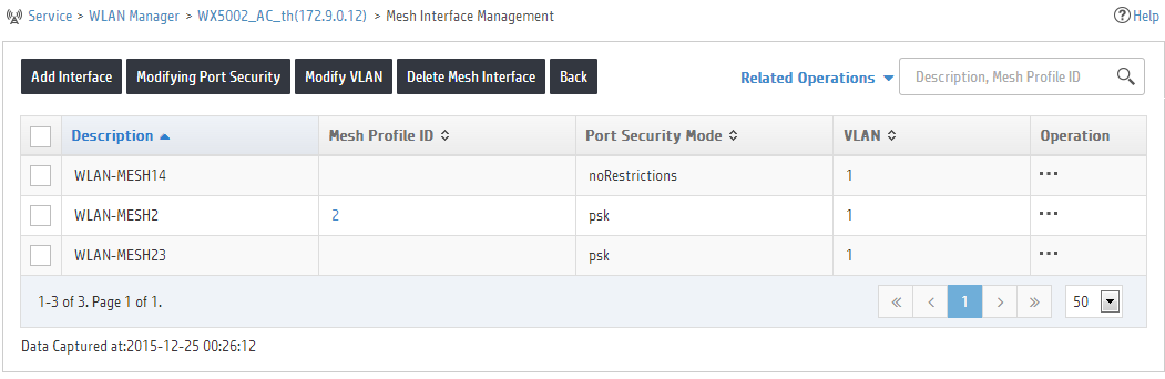
b. Click Add Interface to add a mesh interface, and click Modifying Port Security to configure port security.
6. Configure peer MAC addresses:
a. Enter the Fit AP List page.
- Enter the Device Information page of the AC as shown in Figure 3. In the Wireless Service Information area, click View All.
- Or click the Service tab, select WLAN Manager > Resource Management > ACs from the navigation tree, click the operation icon for the target AC, and select Fit AP List from the menu that appears.
b. Click the target fit AP. On the page that appears, click More Detailed Information at the top right corner to view the detailed AP information as shown in Figure 11.
c. Click the operation icon for the target radio to enter its configuration page. The Configure Mesh Peer MAC Address page appears, as shown in Figure 26.
Figure 26 Configuring peer MAC addresses
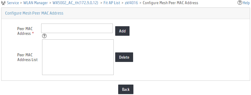
d. Add the peer MAC address as needed.
7. Add a mesh profile for the AC:
a. Enter the Mesh Profile Management page.
- Enter the Device Information page of the AC as shown in Figure 3, and click Mesh Profile Management in the Mesh Management area on the right of the page.
- Or click the Service tab, select WLAN Manager > Resource Management > ACs from the navigation tree, click the operation icon for the target AC, and select Mesh Profile Management from the menu that appears. The Mesh Profile Management page appears, as shown in Figure 27.
Figure 27 Managing mesh profiles
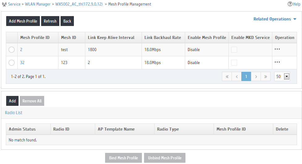
b. Click Add Mesh Profile. The Add Mesh Profile page appears, as shown in Figure 28.
Figure 28 Adding a mesh profile
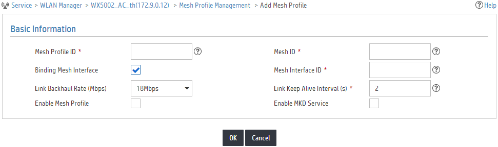
c. Configure the mesh profile ID, mesh ID, mesh interface ID, link keep alive interval, and other information as required, and click OK.
8. Bind a mesh profile for the radio:
a. Enter the Fit AP List page.
- Enter the Device Information page of the AC as shown in Figure 3. In the Wireless Service Information area, click View All.
- Or click the Service tab, select WLAN Manager > Resource Management > ACs from the navigation tree, click the operation icon for the target AC, and select Fit AP List from the menu that appears.
b. Click a fit AP. On the page that appears, click More Detailed Information at the top right corner to view the detailed AP information as shown in Figure 11.
c. On the page that appears, click the modification icon for the target radio. The Modify Radio Parameters page appears, as shown in Figure 29.
Figure 29 Modifying radio parameters

d. Select the mesh profile to be bound, and click OK.
All radios that need to establish mesh links must be bound with a mesh profile.
Verifying the configuration
1. Click the Service tab, and select WLAN Manager > Wireless Topology from the navigation tree.
2. Right-click the AC configured with mesh links, and click Open Mesh Topology.
On the page that appears, you can see the mesh link configured in this example.
