27-H3C IMC EIA Portal Dual-Factor (Account Password + SMS) Authentication for LDAP Users Configuration Examples-book.pdf(2.79 MB)
- Released At: 05-07-2024
- Page Views:
- Downloads:
- Table of Contents
- Related Documents
-
|
|
|
H3C IMC EIA Portal Dual-Factor (Account Password + SMS) Authentication for LDAP Users Configuration Examples |
|
|
|
|
Software Version: EIA 7.3 (E0628)
Document version: 5W108-20230627
Copyright © 2023 New H3C Technologies Co., Ltd. All rights reserved.
No part of this manual may be reproduced or transmitted in any form or by any means without prior written consent of New H3C Technologies Co., Ltd.
Except for the trademarks of New H3C Technologies Co., Ltd., any trademarks that may be mentioned in this document are the property of their respective owners.
The information in this document is subject to change without notice.
Introduction
In scenarios deployed with an application system, an LDAP server is typically used for managing endpoint user accounts. To protect existing investments and save configuration workload on the IMC system, you can install the IMC EIA component to authenticate user validity by using the user accounts on the LDAP server. IMC EIA can work with the LDAP server to provide real-time authentication (LDAP authentication) or local authentication (local authentication through IMC).
Application scenarios
The following information applies to the scenario where an application system uses an LDAP server to manage endpoint user accounts and IMC EIA performs authentication on access users.
Prerequisites
The access devices support the portal protocol and EIA supports LDAP features.
Example: Configuring portal dual-factor (account password + SMS) authentication for LDAP users with IMC EIA
Network configuration
As shown in Figure 1, use an EIA server to provide portal authentication and SMS verification for users who try to access the network resources. Configure the network as follows:
· Set the IP address of the EIA server to 192.168.7.220.
· Set the IP address of the VLAN interface where GigabitEthernet 1/0/29 (user-side interface of the access device) resides to 172.18.76.1.
· Obtain the IP address of the PC through a DHCP server. In this example, the obtained IP address is 172.18.76.9.
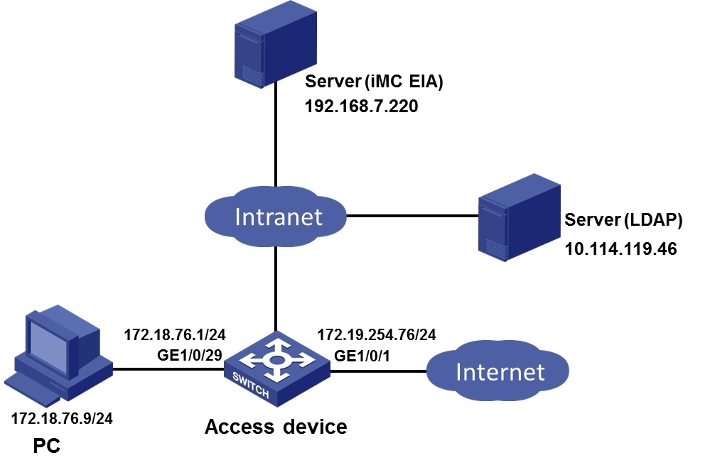
Software versions used
This configuration example was created and verified on EIA 7.3 (E0628), access device H3C S5820V2-54QS-GE, and iNode PC 7.3 (E0589).
Procedures
To configure portal dual-factor (account password + SMS) authentication, complete the following tasks:
· Configuring the EIA server
¡ Adding an access device
¡ Adding an access policy
¡ Adding an access service
· Adding an access user
¡ Configuring the LDAP server
¡ Configure an LDAP synchronization policy
¡ Synchronizing LDAP users to IMC
· Configuring a portal service
¡ Configuring a portal server
¡ Configuring an IP group
¡ Configuring a portal device
· Configuring the SMS service
· Configuring the access device
Configuring the EIA server
Adding an access device
You must add an access device to the EIA server before the EIA server can work with the access device for authentication.
To add a device:
1. Log in to IMC and click the User tab.
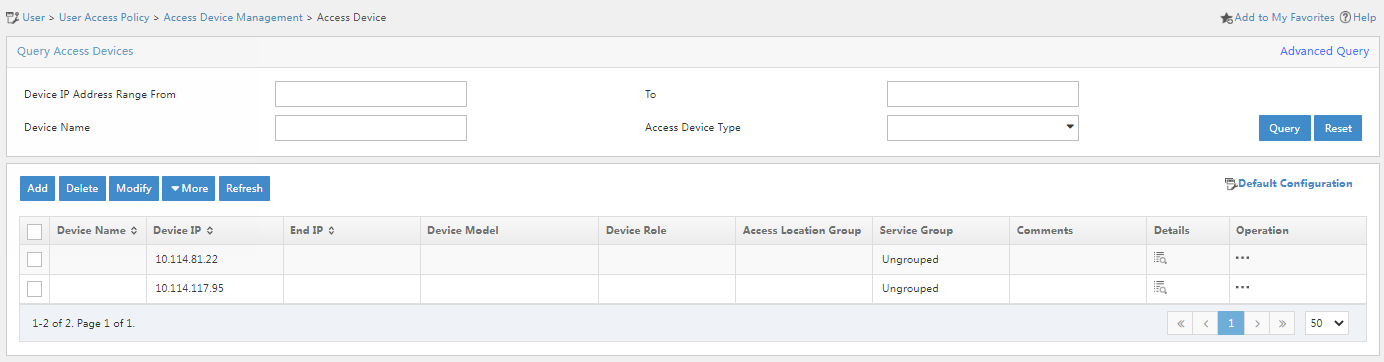
2. From the navigation pane, select User Access Policy > Access Device Management > Access Device.
Figure 2 Access device configuration page
3. Click Add.
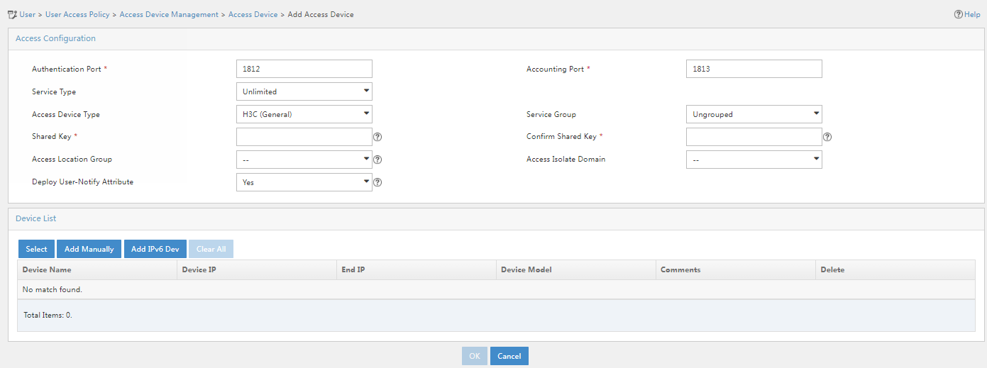
Figure 3 Adding an access device
4. Add an access device.
Use one of the following methods to add the access device:
¡ In the device list, click Select and select a device from IMC.
¡ In the device list, click Add Manually and manually configure the access device.
Make sure the IP address of the access device on EIA meets the following requirements:
¡ If a NAS IP address is specified for the access device (by using the nas-ip command in a RADIUS scheme), the IP address of the access device on the EIA server must be the specified NAS IP address.
¡ If no NAS IP address is specified, the IP address of the access device on the EIA server must be the IP address of the Layer 3 Ethernet interface or VLAN interface that connects the access device to the EIA server.
If you select a device from IMC, you cannot change the IP address of the device. If the device on IMC does not meet the above requirements, do not select it from IMC but manually add the device. In this example, the access device is manually added.
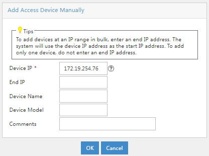
In this example, click Add Manually in the Device List area. In the window that opens, enter the IP address of the access device in the Device IP field, and then click OK.
Figure 4 Manually adding an access device
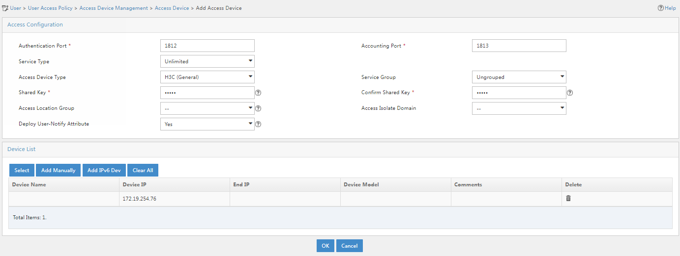
5. Configure the following common parameters:
¡ Authentication Port: Specify a port number for EIA to listen for RADIUS authentication packets. The authentication port must be the same as that specified in the RADIUS scheme on the access device. By default, the authentication port is 1812 on the EIA server and the access device.
¡ Accounting Port: Specify a port for EIA to listen for RADIUS accounting packets. The accounting port must be the same as that specified in the RADIUS scheme on the access device. By default, the accounting port is 1813 on the EIA server and the access device.
|
|
IMPORTANT: You must use the EIA server to provide both authentication and accounting services. You cannot use the EIA server as the authentication server and another server as the accounting server. |
¡ Service Type: Specifies the type of service supported by the access device.
¡ Forcible Logout Type: Specifies a method that forces users to log out. Options include Disconnect user and Shut down and bring up port. The former disconnects user connections through disconnect messages. The latter logs out users by shutting down the port connecting to them, and then brings up the port after the users are logged out.
¡ Access Device Type: Select the access device type from the list.
|
Categories of access device types |
Options |
|
Standard |
STANDARD (Standard) NOTE: You can select this option for any access devices that support the standard RADIUS protocol. |
|
Pre-defined, vendor-specific |
· H3C (General). · 3COM (General). · HUAWEI (General). · CISCO (General). · RG (General). · HP (MSM). · HP (Comware). · MICROSOFT (General). · JUNIPER (General). · HP (ProCurve). · ARUBA (General). |
|
Administrator-defined, vendor-specific |
Available options depend on the configuration. |
¡ Service Group: Select a service group for the access device for hierarchical management.
¡ Shared Key/Confirm Shared Key: Specify a shared key and confirm it. The access device and the EIA server use the shared key to validate each other. The shared key must be the same as that configured in the RADIUS scheme on the access device. You only need to enter the shared key once if you selected Plaintext in the Displays Key in field on the User > User Access Policy > Service Parameters > System Settings > System Parameters page.
¡ Access Location Group: Select an access location group for the access device. The access location group is one of the user access conditions.
¡ Use the default settings for other parameters.
In this example, you only need to enter shared key movie and confirm the key, as shown in Figure 5.
Figure 5 Configuring common parameters
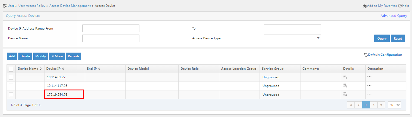
6. Click OK. Click Back to Access Device List to go back to the access device configuration page. Verify that the access device has been added to the access device list.
Figure 6 Verifying that the access device has been added
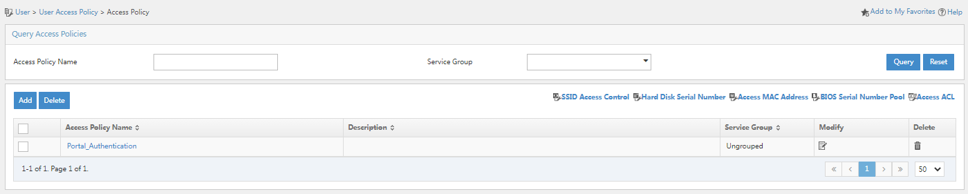
Adding an access policy
This example adds an access policy that does not contain any user-defined access control settings.
To add an access policy:
1. Click the User tab.
2. From the navigation pane, select User Access Policy > Access Policy.
Figure 7 Access policy management page
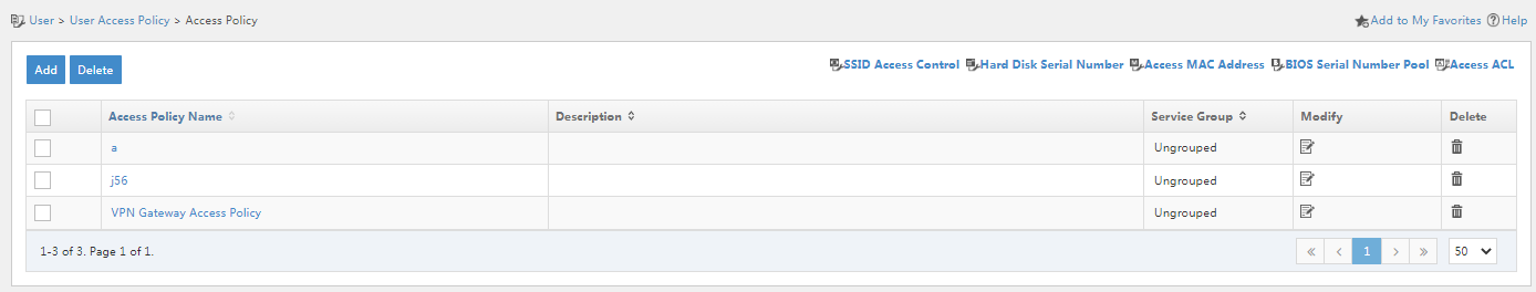
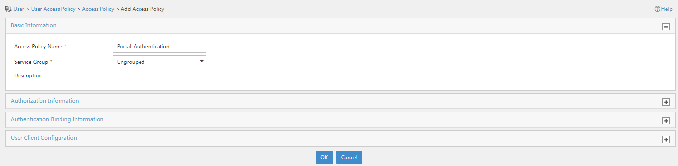
3. Click Add. On the page that opens, configure the access policy as needed. For the purpose of this example, enter the access policy name, and use the default settings for other parameters.
Figure 8 Adding an access policy
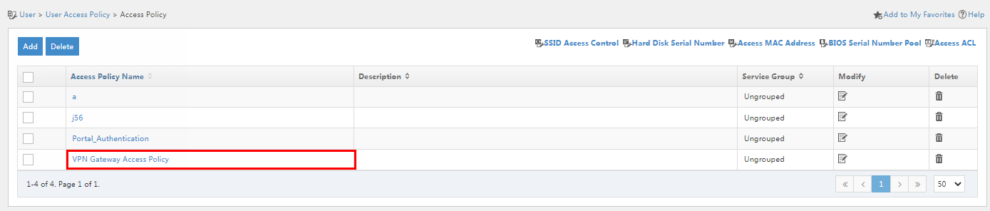
4. Click OK. Go back to the access policy management page. Verify that the access policy has been added to the access policy list.
Figure 9 Verifying that the access policy has been added
Adding an access service
An access service is a collection of policies for user authentication and authorization. This example adds a simple access service that does not contain any access control settings.
To add an access service:
1. Click the User tab.
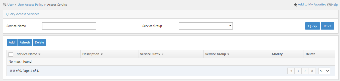
2. From the navigation pane, select User Access Policy > User Access Policy.
Figure 10 Access service management page
3. Click Add, and configure the relevant parameters on the page that opens.
Figure 11 Adding an access service
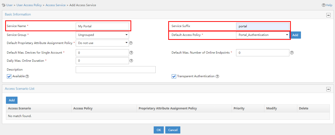
Access service parameters
¡ Service Name: Enter a service name. Make sure the name is unique on the EIA server.
¡ Service Suffix: Enter a service suffix, which identifies the name of the domain to be used for user authentication. The service suffix, authentication username, authentication domain, and the device's RADIUS scheme command are closely related to each other. For more information about the matrix of these elements, see Table 1.
¡ Default Access Policy: Specify an access policy as the default access policy.
¡ Default Security Policy: Specify the security policy applied to users in access scenarios that are not included in the service. The security policy is used to check and monitor user endpoints for security issues and to automatically defend the network. This field is displayed only when the EAD component is installed.
¡ Default Internet Access Policy: Specify the Internet access policy applied to users in access scenarios that are not included in the service.
¡ Default Proprietary Attribute Assignment Policy: Specify the default proprietary attribute assignment policy applied to users in access scenarios that are not included in the service. EIA deploys proprietary attributes to the access device according to the specified default proprietary attribute assignment policy.
¡ Default Max. Devices for Single Account: Maximum number of endpoints to be bound to the same user account in access scenarios that are not included in the service. This field is displayed only when the EIP component is installed.
¡ Default Max. Number of Online Endpoints: Maximum number of online endpoints using the same user account in access scenarios that are not included in the service.
¡ Daily Max. Online Duration: Total duration in a day that an account can access the network by using the service. When the limit is reached, the account is forced offline and is unable to access the network in the day. This parameter is an integer in the range of 0 to 1440 minutes. A value of 0 means not limited.
¡ Use the default settings for other parameters.
|
Authentication username |
Authentication domain |
Device's RADIUS scheme command |
Service suffix on EIA |
|
X@Y |
Y |
user-name-format with-domain |
Y |
|
user-name-format without-domain |
No suffix |
||
|
X |
[Default Domain] Default domain on the device |
user-name-format with-domain |
[Default Domain] |
|
user-name-format without-domain |
No suffix |
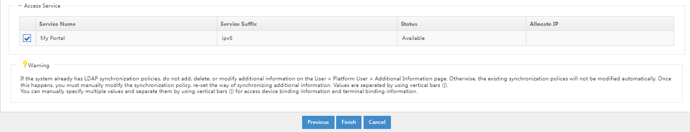
4. Click OK. Go back to the service management page. Verify that the access service has been added to the access service list.
Figure 12 Verifying that the access service has been added

Adding an access user
Configuring the LDAP server
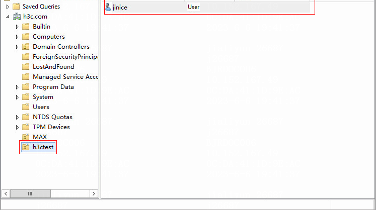
1. Open Microsoft Active Directory, and Add user jinice in the directory h3c.com > h3ctest.
Figure 13 Active Directory Users and Computers window
2. Log in to H3C IMC. Click the User tab, and select User Access Policy > LDAP Service > LDAP Server from the navigation pane. Click Add, and configure the relevant parameters on the page that opens.
Figure 14 Adding an LDAP server
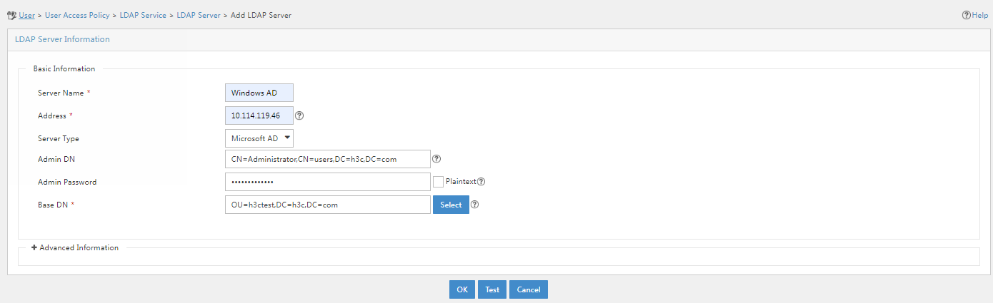
LDAP server parameters
¡ Server Name: Specify a name for the LDAP server. The service name cannot be empty, and cannot be duplicate with an existing one
¡ Address: Specify an IP address or domain name for the LDAP server. The combination of this parameter and the base DN must be unique.
¡ Server Type: Specify the type of the LDAP server. Options include General and Microsoft AD. The former refers to a generic LDAP server compliant with the LDAP standards. The latter refers to Microsoft Active Directory.
¡ Administrator DN: Administrator DN of the LDAP server, for managing user data in the LDAP server.
In this example, because the domain of the LDAP server is h3c.com, the administrator name is Administrator, and the administrator belongs to user group Users, the administrator DN is configured as CN=Administrator,CN=users,DC=h3c,DC=com.
¡ Admin Password: Administrator password of the LDAP server. The system uses this password when establishing a connection with the LDAP server.
¡ Plaintext: Specify whether to display the administrator password in plaintext form. For security purposes, after you select this option, you must enter the administrator password again for confirmation.
¡ Base DN: Name of the root node that stores user data in the LDAP server. The value must be an absolute path. You can use either of the following methods to configure a base DN:
- Select—To select a base DN, click Select. On the page that opens, click Query to refresh the base DN list, and then select the target base DN.
To obtain all base DN information of a server for selection, make sure you have entered the correct server address, administrator DN, and administrator password.
- Manually enter—Enter a base DN and use commas (,) or semicolons (;) as the separator. Suppose the server type is Microsoft AD, the domain of the LDAP server is h3c.com, the domain contains organization unit (OU) group1, and OU test exists in OU group1. To add an LDAP server with group1 as the root node, configure the base DN as OU=group1,DC=h3c,DC=com. To add an LDAP server with test as the root node, configure the base DN as OU =test,OU=group1,DC=h3c,DC=com.
3. Expand the Advanced Information area, and configure the service sync type and the real-time authentication feature.
Figure 15 Configuring advanced information for the LDAP server
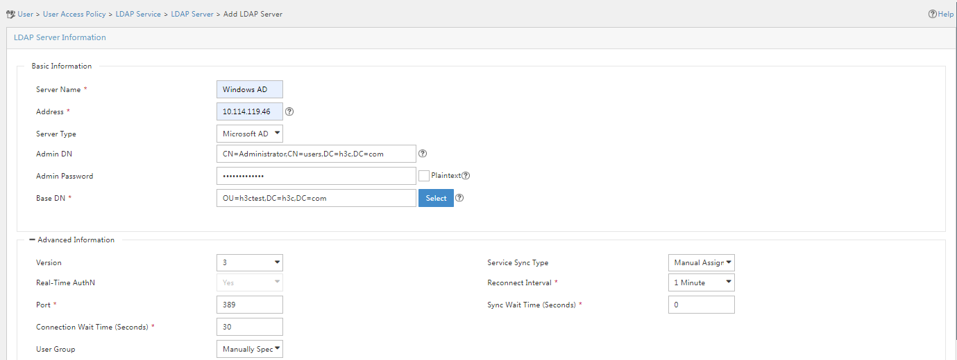
LDAP server parameters
¡ Service Sync Type: Specify the method for synchronizing users on the LDAP server to IMC. Options include Manual Assignment and Based on Active Directory Group. If you set the server type to General, the service sync type must be Manual Assignment. If you set the server type to Microsoft AD, the service sync type can be Manual Assignment or Based on Active Directory Group. This example uses Manual Assignment.
- Manual Assignment—When you configure a synchronization policy for the LDAP server, you can specify services for users.
- Based on Active Directory Group—When you configure a synchronization policy for the LDAP server, you can only specify services for LDAP groups and the system will assign services for users based on the LDAP groups to which the users belong.
You can manually specify a service for each user, or specify the same set of services for all users. Because an LDAP server may have thousands of users that use different services, manual assignment is inefficient and tedious. Considering that users belong to LDAP groups, AD group-based synchronization allows you to associate a service with an LDAP group. In this way, users in the LDAP group can request the service associated with the LDAP group, which greatly reduces the maintenance workload.
¡ Real-Time AuthN: With real-time authentication enabled, bound users are authenticated on the LDAP server. With real-time authentication disabled, bound users are locally authenticated on EIA. The Microsoft AD LDAP server supports only real-time authentication because it does not have the user password query interface. The general LDAP server supports synchronizing user passwords to EIA and you can select local authentication.
¡ Use the default settings for other parameters.
4. After completing the configuration, click Test to detect the connectivity with the LDAP server.
Figure 16 Testing LDAP server connectivity
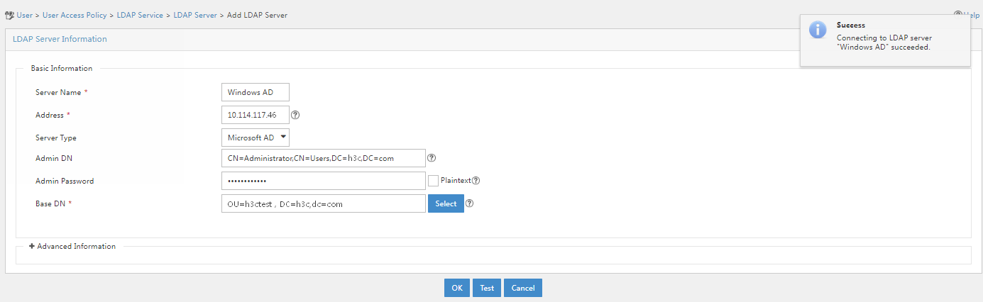
5. Click OK after the test succeeded.
Configuring an LDAP synchronization policy
|
|
NOTE: This example configures an auto synchronization policy. |
LDAP synchronization allows automatic synchronization of users on an LDAP server to IMC.
To configure an LDAP synchronization policy:
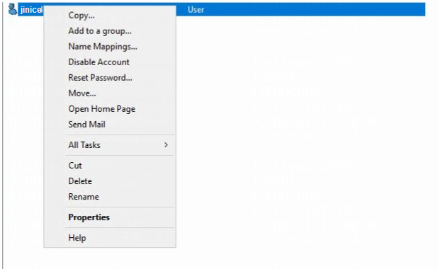
1. Open the Active Directory Users and Computers window, click h3ctest under the h3c.com node from the navigation pane. Right-click user jinice.
Figure 17 Selecting the LDAP user to be synchronized
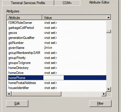
2. Select Properties on the window that opens, click the Attribute Editor tab, view and record the name of the attribute that indicates the phone number of the user. In this example, the attribute name is homePhone.
Figure 18 Attribute Editor window
3. Open IMC. Click the User tab, and select User Access Policy > LDAP Service > LDAP Parameters from the navigation pane. Click Add and configure the relevant parameters on the page that opens.
Figure 19 Adding an LDAP synchronization policy
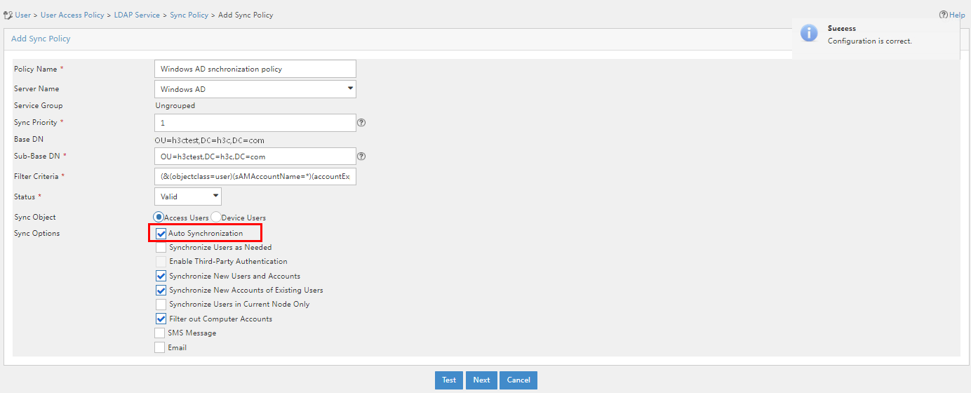
LDAP synchronization policy parameters
¡ Sync Priority: Specifies the priority for an LDAP synchronization policy, which is an integer in the range of 1 to 9999. The greater the value, the higher the priority. EIA executes scheduled LDAP synchronization policies according to their priorities. LDAP synchronization policies can have the same priority and will be executed in a random order.
¡ Sub-Base DN: Enter a sub-base DN. The base DN is the root node that saves user data on the LDAP server. As subsets of the base DN, sub-base DN are used for finer classification and management of user data. In this example, the sub-base DN is the same as the base DN.
¡ Filter Criteria: The basic format is attribute name=value. The value part supports fuzzy match by using an asterisk (*). For example, CN=He* indicates all nodes that have a CN attribute value starting with He. For combined query, you can specify multiple filter criteria by quoting each of them with a pair of parentheses, putting a sign in front of the first left parenthesis to indicate the relationship between them (& for AND, | for OR, ! for NOT), and finally putting the whole string in a pair of parentheses. You can specify the following filter criteria to process expired users for synchronization:
- accountExpires>=now—Use this condition to filter out expired users for synchronization.
- accountExpires<=now—Use this condition to synchronize the current expired users.
- accountExpires>=now+n—Use this condition to filter out expired users and users that will expire in n days.
- accountExpires>=now-n—Use this condition to filter out users that have expired for n days.
- accountExpires<=now+n—Use this condition to synchronize only the expired users and users that will expire in n days.
- accountExpires<=now-n—Use this condition to synchronize only the users that have expired for at least n days.
The letter n is an integer in the range of 1 to 3650.
¡ Status: Specify the status of the synchronization policy. Options include Valid and Invalid. A synchronization policy in the Invalid status cannot be used for synchronization. Users that have been synchronized to IMC by the policy before the policy became Invalid are not affected. They can perform authentication to come online and use self-services.
¡ Sync Object: Specify the sync object. When you add a synchronization policy, select the Access Users type to configure the LDAP synchronization policy for access users.
¡ Sync Options: Specify the sync options for this policy. In this example, Auto Synchronization is selected.
- Auto Synchronization: Enables EIA to synchronize LDAP users at the time specified by the LDAP Sync/Backup Task parameter every day.
- Enable Third-Party Authentication: Select this option to enable third-party authentication for the LDAP users synchronized from this policy. If you do not select this option, LDAP users synchronized from this policy will use LDAP authentication. This option is available only when you configure the third-party authentication.
- Synchronize New Users and Accounts: With this option selected, if a user exists on the LDAP server but does not on IMC, the user will be added to IMC and an access user will be added to the EIA component accordingly during synchronization.
- Synchronize New Accounts of Existing Users: With this option selected, if a user exists on both the LDAP Server and IMC but no corresponding access user exists on the EIA component, an access user will be added to the EIA component accordingly during synchronization.
- Synchronize Users in Current Node Only: If you select this option, IMC synchronizes users in the current sub-base DN only but does not synchronize any subordinate OU users. If you do not select this option, IMC synchronizes users in the sub-base DN and all subordinate OUs.
- Filter out Computer Accounts: This option enables EIA to filter out computer accounts during LDAP synchronization. Clear this option if you want to synchronize computer accounts from the LDAP Server.
¡ Use the default settings for other parameters.
4. After completing the configuration, click Test to detect connectivity. After completing the test, click Next to open the LDAP policy management page. Click the Modify icon for the LDAP policy. Select the obtained attribute name in the Telephone filed, and specify the password synchronization method and service name.
Figure 20 Selecting the obtained attribute name
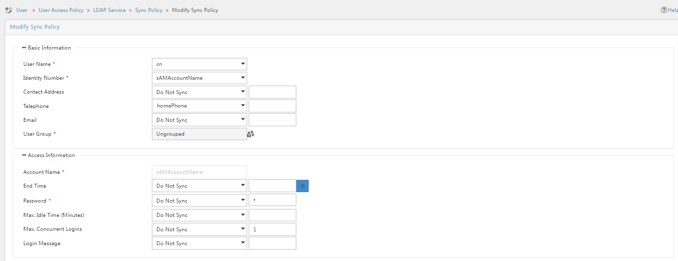
Figure 21 Selecting an access service
5. Click OK.
Synchronizing LDAP users to IMC
|
|
NOTE: You can use the LDAP synchronization feature to synchronize LDAP users on the LDAP server to IMC. The LDAP user information will be synchronized every morning (IMC server time) in periodic LDAP synchronization. You can also click the Synchronize link for the LDAP synchronization policy to immediately synchronize the LDAP user information. To view the synchronization result, click Most Recent Sync Result. |
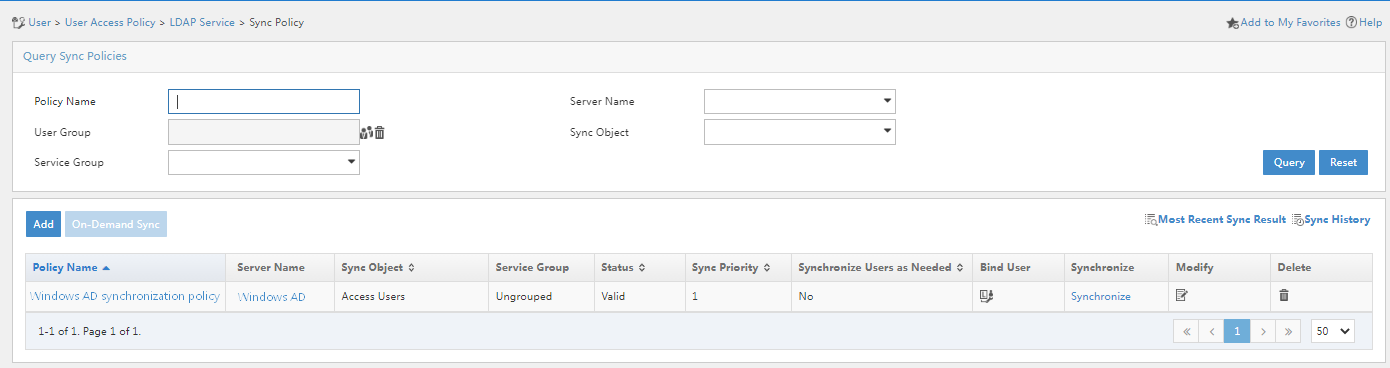
After completing the synchronization policy configuration, you can view the added synchronization policy in the synchronization policy list.
Figure 22 Synchronization policy list
To synchronize LDAP users to IMC:
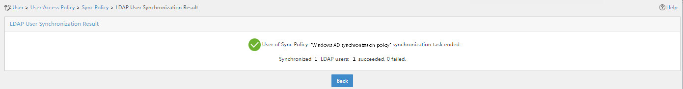
1. Click the Synchronize link for the synchronization policy to start synchronization.
Figure 23 Synchronizing the LDAP users
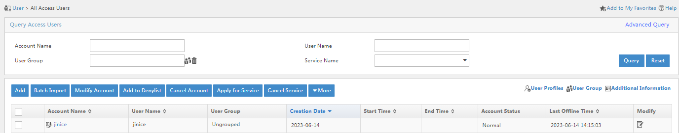
2. Click the User tab, and select Access User > All Access Users from the navigation pane. Verify that LDAP user jinice has been synchronized to the access user list.
Figure 24 LDAP user synchronization results
Configuring a portal service
Configuring a portal server
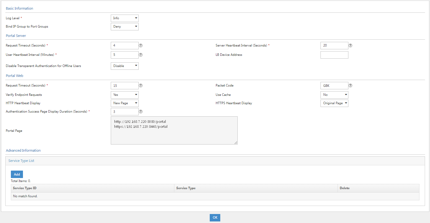
1. Click the User tab, and select User Access Policy > Portal Service > Server from the navigation pane.
Figure 25 Server configuration page
2. In the Advanced Information area, click Add next to Service Type List. On the page that opens, enter the service type ID and service type.
Figure 26 Adding a service type
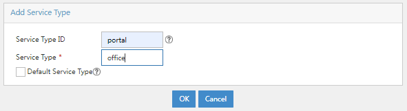
Service type parameters
¡ Service Type ID: Specify the service type ID. Make sure the service type ID is the same as the service suffix of the added access service.
¡ Service Type: Specify the service type. This parameter is a description and identification for the service type ID.
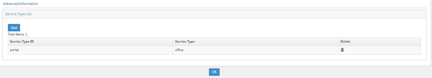
3. Click OK. Go back to the service configuration page. Verify that the service type has been added to the service type list.
Figure 27 Verifying that the service type has been added
4. Click OK.
Configuring an IP group
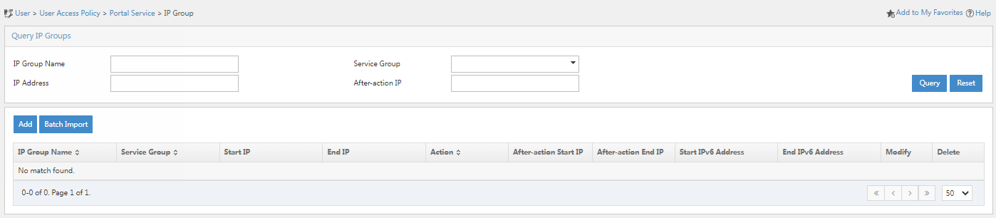
1. Click the User tab, and select User Access Policy > Portal Service > IP Group from the navigation pane.
Figure 28 IP group configuration page
2. Click Add.
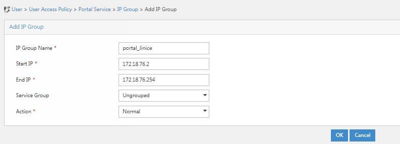
3. Enter the IP group name, start IP, and end IP. In this example, IP group name portal_Jinice, start IP 172.18.76.2, and end IP 172.18.76.254 are used. The system performs authentication on all endpoints in the IP address range.
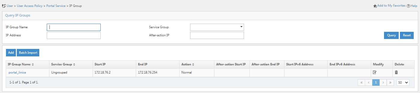
4. Click OK. Go back to the IP group configuration page. Verify that the IP group has been added to the IP group list.
Figure 30 Verifying that the IP group has been added
Configuring a portal device
1. Click the User tab, and select User Access Policy > Portal Service > Device from the navigation pane.
Figure 31 Portal device configuration page
2. Click Add and configure the relevant parameters on the page that opens.
Figure 32 Adding a portal device
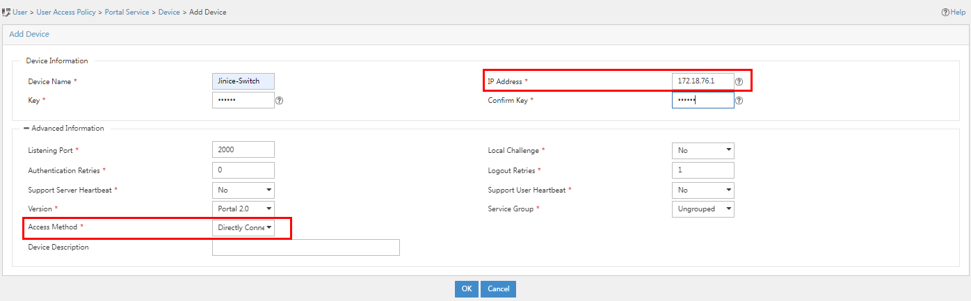
Portal device parameters
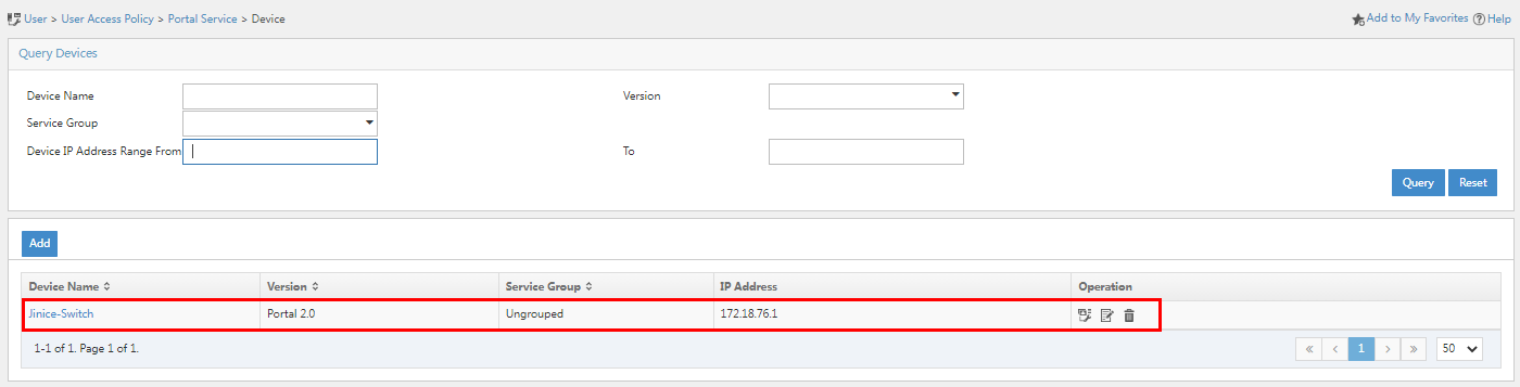
¡ Device Name: Name of the device. This example uses Jinice-Switch.
¡ IP Address: IP address of the device. This example uses 172.18.76.1.
¡ Key/Confirm Key: Enter a key and confirm it. The key must be the same as that configured on the access device for the portal server. In this example, iMC123 is used.
¡ Access method: Select the authentication mode used by the device. In this example, Directly Connected is used.
¡ Use the default settings for other parameters.
3. Click OK. Go back to the device configuration page. Verify that the portal device has been added to the portal device list.
Figure 33 Verifying that the portal device has been added
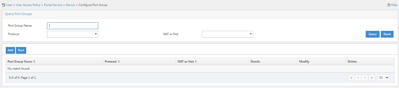
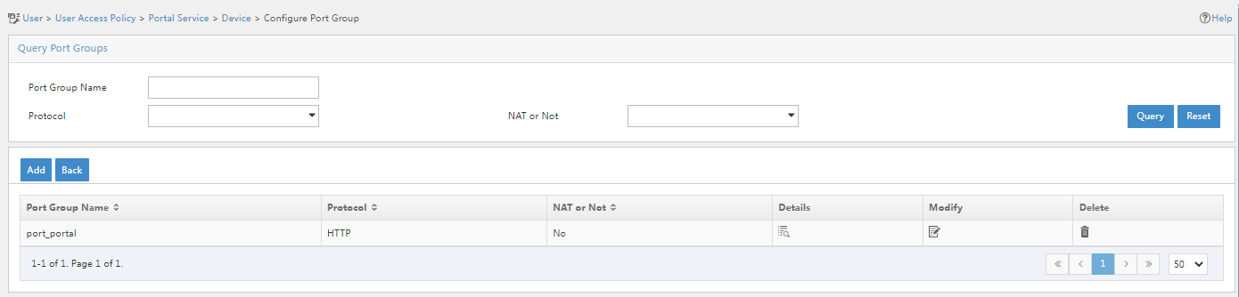
4. Click the Port Group
icon ![]() in the Operation column for the portal device.
in the Operation column for the portal device.
Figure 34 Port group configuration page
5. Click Add and configure the relevant parameters on the page that opens.
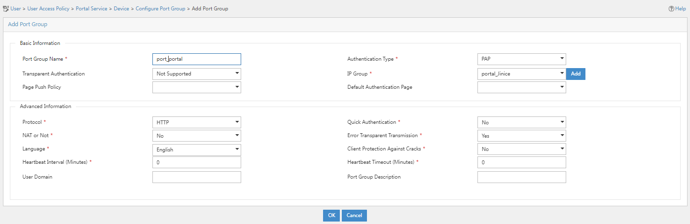
Port group parameters
¡ Port Group Name: Specify the port group name. In this example, port_portal is used.
¡ Authentication Type: Specify the authentication type. In this example, PAP is used.
¡ IP Group: Specify the IP group. In this example, portal_Jinice is used.
¡ Use the default settings for other parameters.
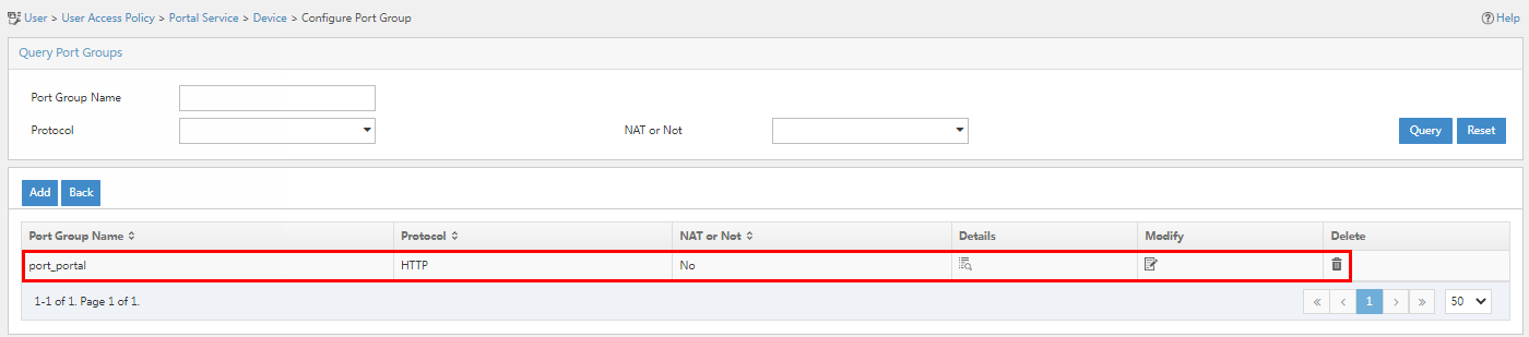
6. Click OK. Go back to the port group configuration page. Verify that the port group has been added to the port group list.
Figure 36 Verifying that the port group has been added
Configuring the SMS service
|
|
NOTE: This example uses SMS Sender to provide the SMS service for portal dual-factor authentication. To use the SMS Sender function, make sure the IMC server can communicate with the SMS Sender. |
1. Navigate to the System > System Configuration > SMSC Settings page.
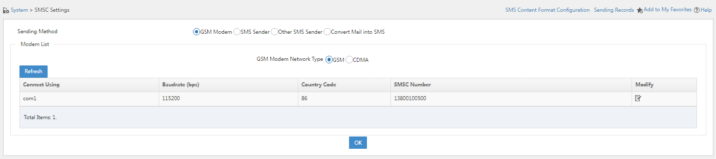
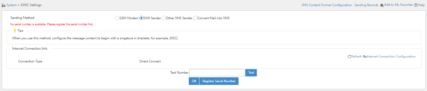
2. Select SMS Sender and click Registration Serial Number.
Figure 38 SMS Sender configuration page
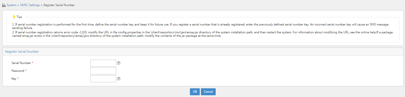
3. Specify the registration serial number and other parameters, and then click OK.
Figure 39 Registration serial number configuration page
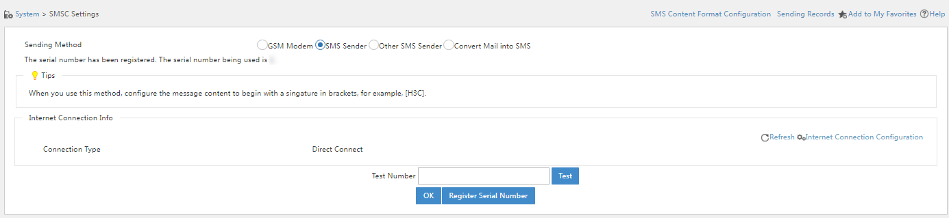
4. Enter a phone number in the Test Number filed and then click Test to test the connectivity of the phone number.
Figure 40 Successful registration
Configuring the access device
Configure the access device to perform portal authentication on users to ensure that only users who have passed the authentication can access the network resources.
Log in to the CLI of the access device, for example, through Telnet:
1. Enter system view.
<Device>system-view
System View: return to User View with Ctrl+Z.
2. Specify the RADIUS scheme:
# Create RADIUS scheme allpermit.
[Device]radius scheme allpermit
New Radius scheme
# Specify the EIA server as both the authentication server and accounting server. Configure the authentication port, accounting port, and shared keys. Make sure the settings are the same as those configured in "Adding an access device."
[Device-radius-allpermit]primary authentication 192.168.7.220 1812
[Device-radius-allpermit]primary accounting 192.168.7.220 1813
[Device-radius-allpermit]key authentication simple movie
[Device-radius-allpermit]key accounting simple movie
[Device-radius-allpermit]user-name-format with-domain
[Device-radius-allpermit]nas-ip 172.19.254.76
[Device-radius-allpermit]quit
3. Create an ISP domain named portal and apply RADIUS scheme allpermit to the ISP domain: The name of the ISP domain must be the same as the service suffix configured in "Adding an access service."
[Device]domain portal
New Domain added.
[Device-isp-portal]authentication portal radius-scheme allpermit
[Device-isp-portal]authorization portal radius-scheme allpermit
[Device-isp-portal]accounting portal radius-scheme allpermit
[Device-isp-portal]quit
4. Configure the portal authentication server:
# Create portal authentication server myportal.
[Device]portal server myportal
New portal server added.
# Specify the IP address of the EIA server as the IP address of the portal authentication server, and set the shared key for communication with the portal authentication server. The key must be the same as that configured in "Configuring a portal device."
[Device-portal-server-myportal]ip 192.168.7.220 key simple iMC123
[Device-portal-server-myportal]quit
5. Create portal Web server myportal, and specify a URL for the portal Web server. Make sure the URL is the same as the http or https URL in the Portal Page field configured on EIA in "Configuring a portal server." You can view the portal server configurations on EIA in Figure 25.
[Device]portal web-server myportal
New portal web-server added.
[Device-portal-websvr-myportal]url http://192.168.7.220:8080/portal
[Device-portal-websvr-myportal]quit
6. Assign GigabitEthernet 1/0/29 to VLAN 21.
[Device]interface gigabitethernet 1/0/29
[Device-gigabitethernet1/0/29]port link-mode brige
[Device-gigabitethernet1/0/29]port access vlan 21
[Device-gigabitethernet1/0/29]quit
7. Configure portal authentication:
# Enable direct portal authentication on VLAN-interface 21 where GigabitEthernet 1/0/29 resides.
[Device]interface Vlan-interface 21
[Device-Vlan-interface21]ip address 172.18.76.1 255.255.255.0
[Device-Vlan-interface21]portal enable method direct
# Specify portal Web server myportal on VLAN-interface 21.
[Device-Vlan-interface21]portal apply web-server myportal
# Configure the BAS-IP for portal packets sent to the portal authentication server. Make sure the BAS-IP is the same as the IP address configured on EIA in "Configuring a portal device."
[Device-Vlan-interface21]portal bas-ip 172.18.76.1
[Device-Vlan-interface21]quit
Verifying the configuration
Performing authentication by using the iNode client
Modifying the access policy
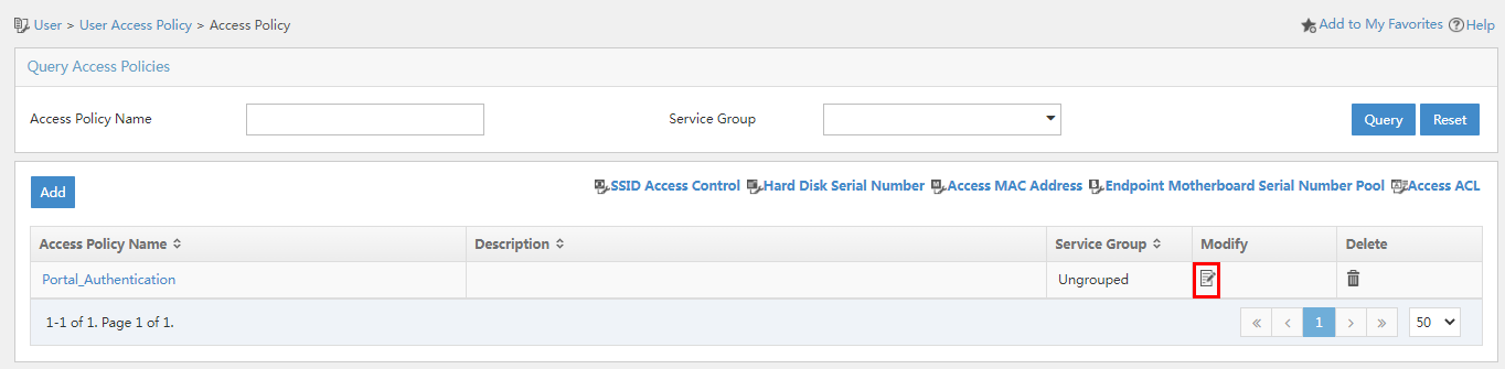
1. Click the User tab, and select User Access Policy > Access Policy from the navigation pane.
Figure 41 Access policy configuration page
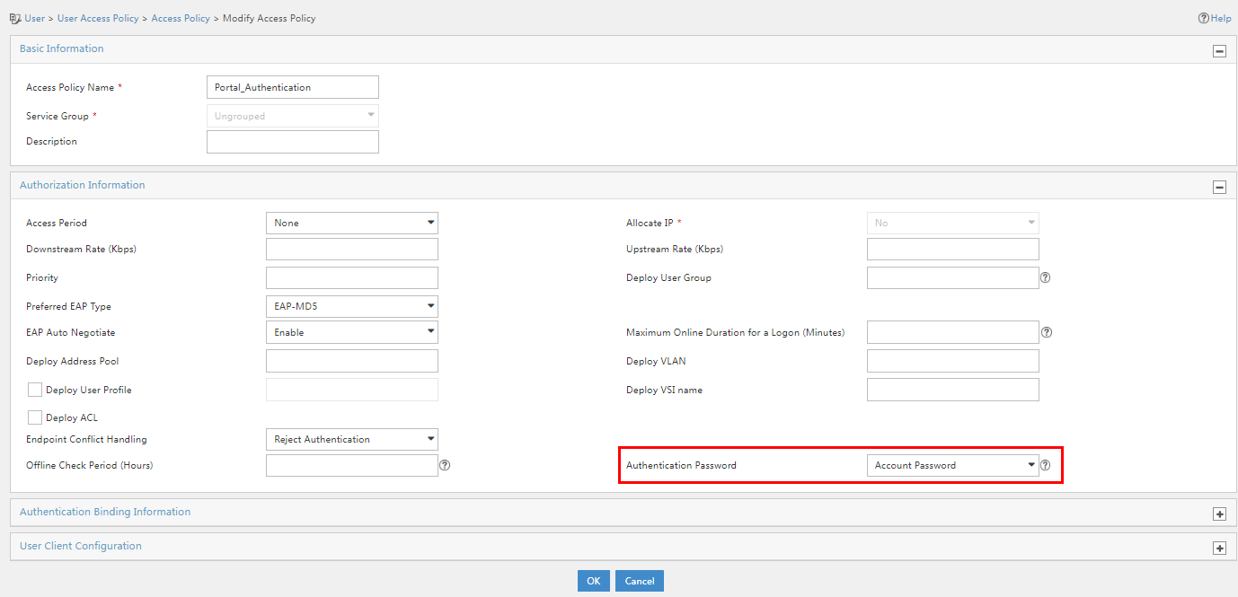
2. Click the Modify icon for the target access policy. In the Authorization Information area, select Account Password + Dynamic Password in the Authentication Password field.
Figure 42 Modifying the access policy
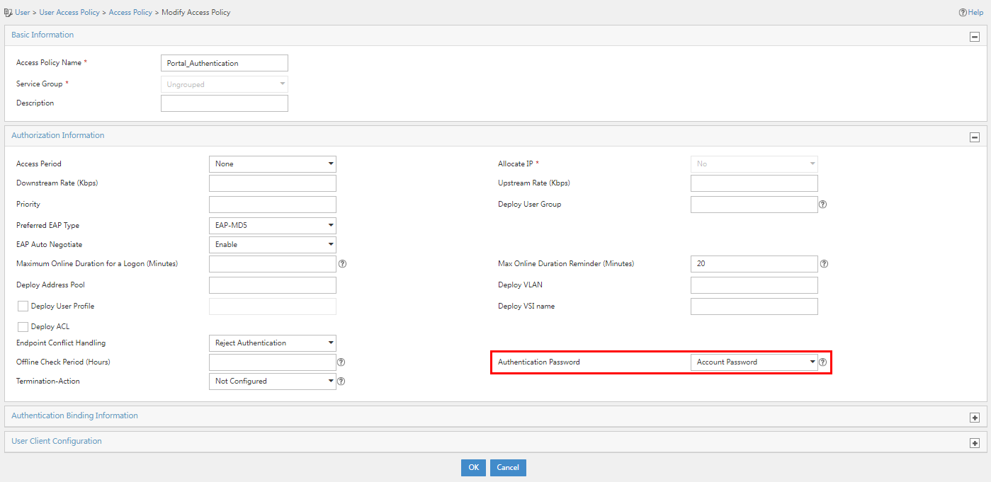
|
|
IMPORTANT: · Because dynamic passwords are supported in only PAP, EAP-MD5, EAP-PEAP/EAP-MD5, and EAP-PEAP/EAP-GTCS authentication methods, if you select Dynamic Password or Account Password + Dynamic Password, you must configure one of the mentioned authentication methods on iNode. · The Account Password + Dynamic Password method is applicable only to iNode client authentication. |
Configuring the iNode client to support dual-factor authentication
1. Open the iNode Management Center. From the navigation tree, select Client Customization.
Figure 43 Customizing the iNode client
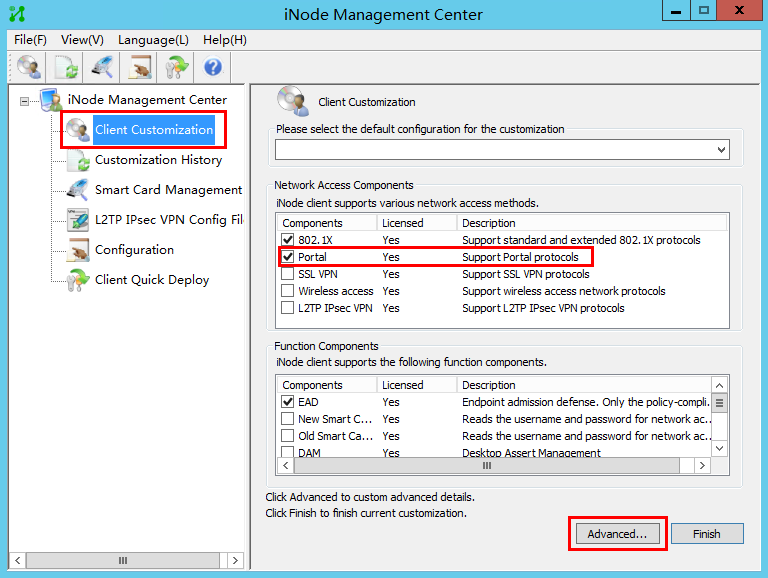
2. Select the Portal network access component and the DAM function component, and then click Advanced….
3. Click the Basic Functions tab, select the check box before Enable SMS verification code.
4. On the window that opens, select the check box before Allow Users to Modify, enter the server IP address and serve port. In this example, the IP address is that of the EIA portal component.
Figure 44 SMS verification code settings
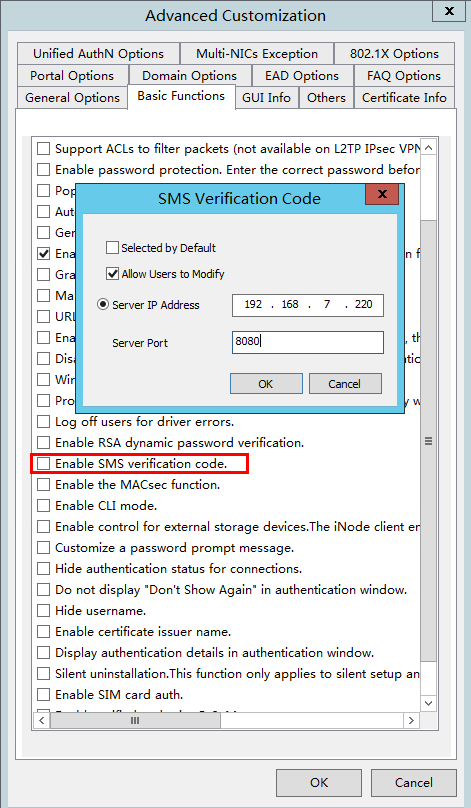
5. Click OK.
|
|
NOTE: For more information about the installation and customization of the iNode client, see iMC iNode Online Help-7.3-5W100 on the official website of H3C. |
Using the iNode client to perform dual-factor portal authentication
1. Open the iNode client, select Portal connection, click More, and then select Properties.
2. On the window that opens, configure the settings as follows.
Figure 45 Portal authentication settings
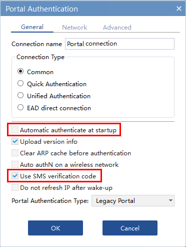
3. Click OK.
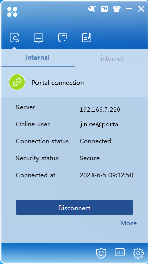
4. Click Refresh to have the iNode client automatically obtain the portal server address. Enter the username and password, select the service type as needed, and then enter the verification code.
5. Click Connect.
When the user passes portal authentication, the authentication result window opens.
Figure 46 Successful connection
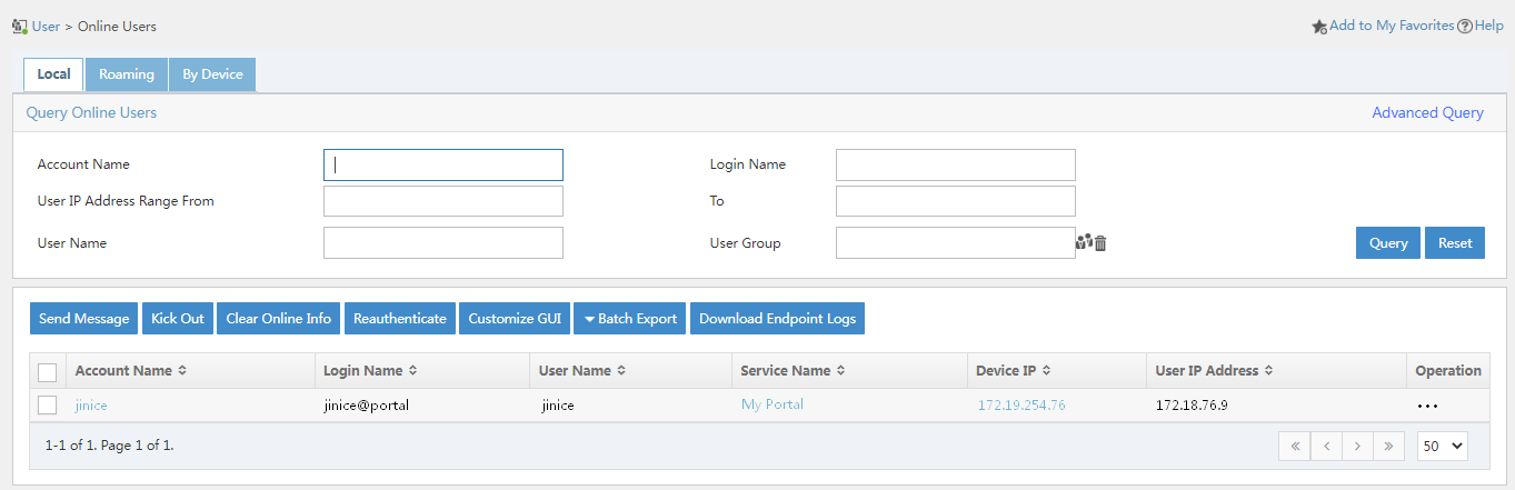
6. On EIA, click the User tab, select Access User > Online Users from the navigation pane to verify that user jince has successfully come online.
Figure 47 Viewing online users

Performing authentication from a Web authentication page
Modifying the portal access policy
1. Click the User tab, and select User Access Policy > Access Policy from the navigation pane.
Figure 48 Access policy configuration page
2. Click the Modify icon for the target access policy. In the Authorization Information area, select Account Password in the Authentication Password field.
Figure 49 Modifying the access policy
|
|
IMPORTANT: To avoid authentication failures, do not select Account Password + Dynamic Password or Dynamic Password in the Authentication Password field in Web-based dual-factor portal authentication. |
Modifying the default Web authentication page or adding a custom portal page
To perform authentication by using a Web authentication page, you can modify the default Web login page or add a custom portal page as needed.
Modifying the default Web authentication page
1. Click the User tab, and select User Access Policy > Customize Terminal Pages > Portal Page from the left navigation pane.
Figure 50 Portal page customization
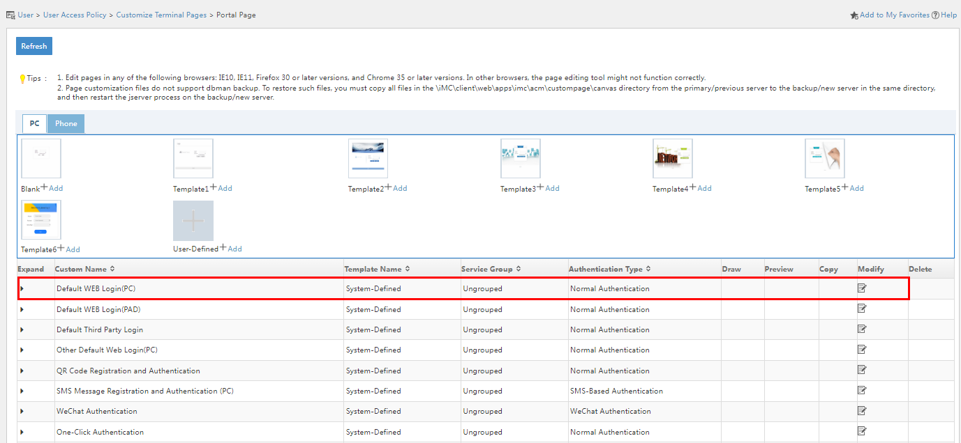
2. Click the Modify ![]() icon
for the Default WEB Login(PC) page.
icon
for the Default WEB Login(PC) page.
Figure 51 Editing the default Web authentication page
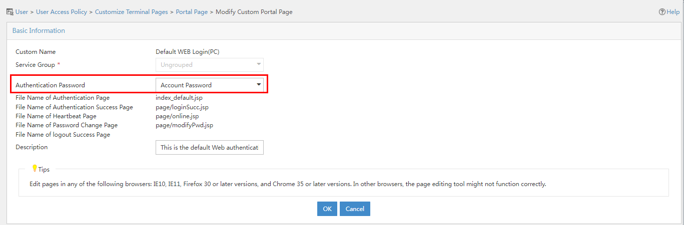
3. On the page that opens, select Account Password + Dynamic Password in the Authentication Password field.
Adding a custom portal page
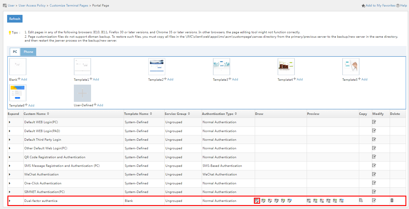
1. Click the User tab, and select User Access Policy > Customize Terminal Pages > Portal Page from the left navigation pane.
Figure 52 Portal page customization
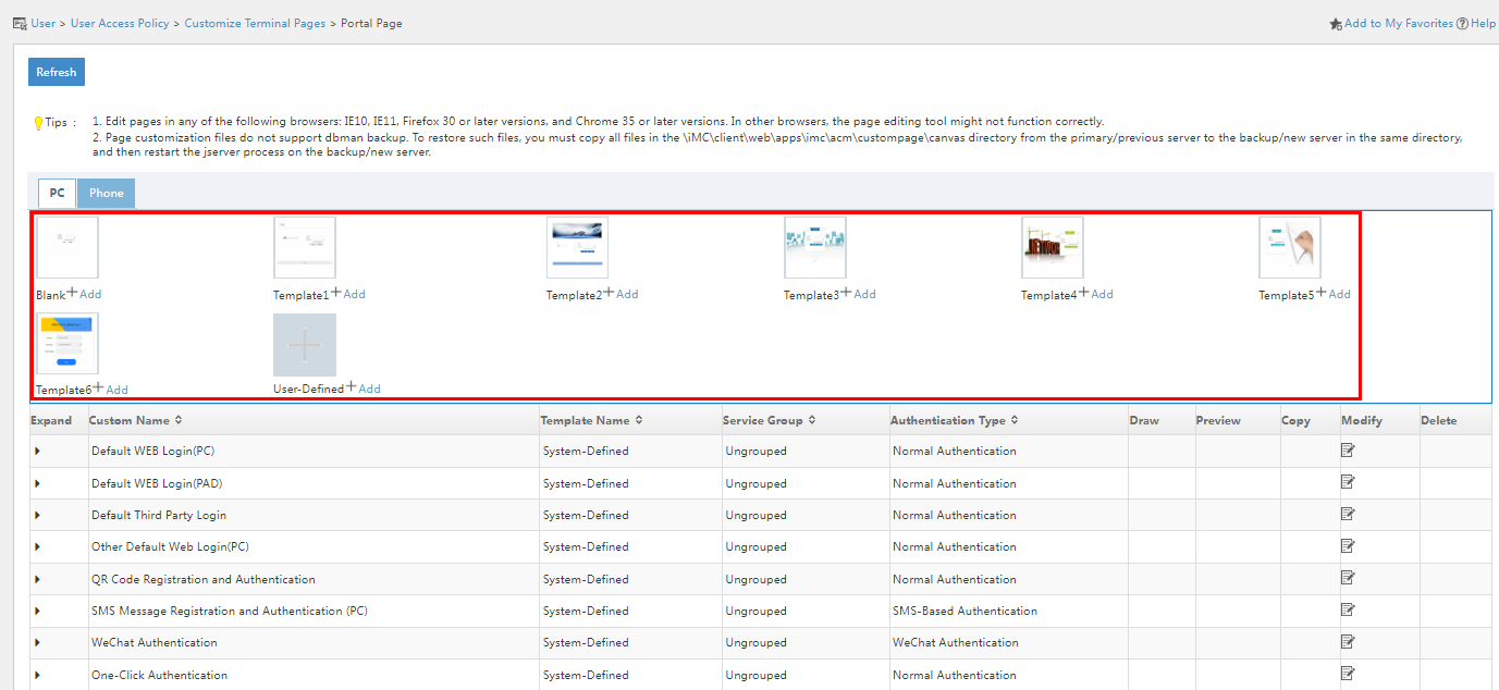
2. In the PC area, select the template as needed. This example adds a custom portal page based on the blank template.
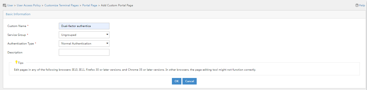
3. On the page that opens, enter the custom name, select Normal Authentication in the Authentication Type field, and then click OK.
Figure 53 Adding a custom portal page
4. Click the ![]() icon
in the Draw column for the custom portal page.
icon
in the Draw column for the custom portal page.
Figure 54 Custom portal page configuration page
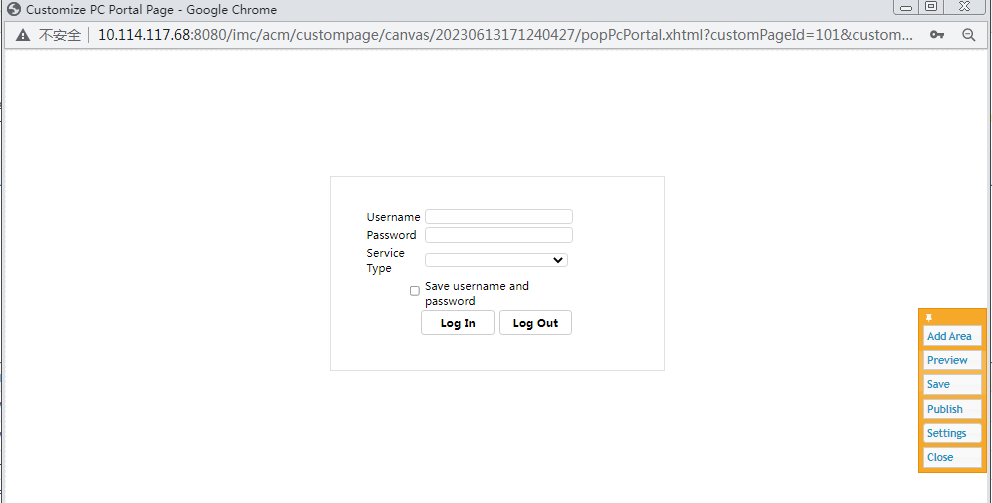
5. Click Settings in the toolbar on the right side of the page. Select Account Password + Dynamic Password from the Authentication Password list and then click OK.
Figure 55 Configuring authentication password
6. Click Save to save the configuration, and then click Close to close the page.
7. On the User tab, and select User Access
Policy > Portal Service > Device from the navigation pane. In
the device list, click the ![]() icon in the Operation column for device Jinice-Switch.
icon in the Operation column for device Jinice-Switch.
Figure 56 Configure Portal Port Group
8. Click the Modify icon ![]() for
port group port_portal.
for
port group port_portal.
9. On the page that opens, select PC – Dual-factor authentication in the Default Authentication Page field.
Figure 57 Modifying the port group
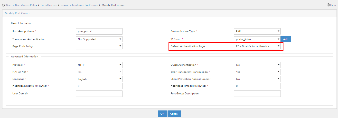
10. Click OK.
Performing dual-factor portal Web authentication
1. Open a browser. When you perform authentication for the first time, type a random address in the address bar, verify that you are redirected to the portal authentication page.
Figure 58 Portal authentication page
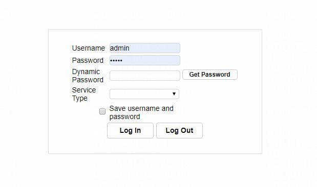
2. Enter LDAP username jinice and the password, obtain the SMS verification code, enter the obtained verification code as the dynamic password, and select the service type. Then click Log In. Verify that the user can successfully come online.
To receive SMS verification codes, make sure you have configured the phone number for the LDAP user.
Figure 59 Login result page
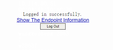
3. On EIA, click the User tab, and select Access User > Online Users from the navigation pane to verify that user jinice has successfully come online.
Figure 60 Viewing online users