21-H3C IMC UAM Roaming Authentication with 802.1X Access Control Configuration Examples-book.pdf(693.57 KB)
- Released At: 05-07-2024
- Page Views:
- Downloads:
- Table of Contents
- Related Documents
-
|
H3C IMC UAM |
|
Roaming Authentication with 802.1X Access Control Configuration Examples |
|
|
Software version: IMC UAM 7.2 (E0402)
|
Copyright © 2016 Hangzhou H3C Technologies Co., Ltd. All rights reserved. No part of this manual may be reproduced or transmitted in any form or by any means without prior written consent of Hangzhou H3C Technologies Co., Ltd. The information in this document is subject to change without notice. |
|
Contents
Example: Roaming authentication with 802.1X access control
Adding the UAM2 server as an access device
Configuring an access user and assigning the service to the user
Configuring UAM1 as the destined authentication server
Adding the switch to UAM2 as an access device
Triggering 802.1X authentication
Introduction
The examples apply to scenarios that require access users to be authenticated on a visited network.
Example: Roaming authentication with 802.1X access control
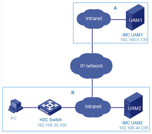
Network configuration
As shown in Figure 1, a company has A and B branches and deploys a UAM server in each branch. UAM on each IMC server manages user accounts for employees who work for that branch.
When an employee in branch A transfers to branch B and attempts to access the public network through 802.1X, the UAM server (UAM2) on branch B forwards the authentication request back to the UAM server (UAM1) on branch A for roaming authentication.
In branch B, the NAS (H3C switch) manages 802.1X users in an ISP domain named roam and includes the domain name in usernames to be sent for authentication.
The switch and UAM2 use the shared key hello for secure RADIUS communication. UAM1 and UAM2 use world for secure RADIUS communication. The RADIUS authentication port is 1812. The RADIUS accounting port is 1813.
Software version used
This example was created and verified on the following platforms:
· IMC UAM 7.2 (E0402)
· H3C S3600V2-28TP-EI Comware Software, Version 5.20, Release 2103
· iNode PC 7.2 (E0402)
Restrictions and guidelines
When you configure the roaming authentication, follow these restrictions and guidelines:
· UAM1 must provide both authentication and accounting services. Do not use another server other than UAM1 to provide the accounting service.
· Make sure the roaming configuration in UAM2 has the same authentication port, accounting port, and shared key settings as the access device configuration in UAM1.
· Make sure the parameters you configure for the access device in UAM2 are the same as the CLI configuration on the switch, such as the authentication and accounting ports and shared key.
· The service suffix configuration varies by the username, authentication domain, and RADIUS commands, as shown in Table 1.
Table 1 Determining the service suffix
|
Username in iNode |
Authentication domain on the switch |
RADIUS commands configured on the switch |
Service suffix in UAM |
|
sam@roam |
roam |
user-name-format with-domain |
roam |
|
user-name-format without-domain |
No suffix |
Configuring UAM1
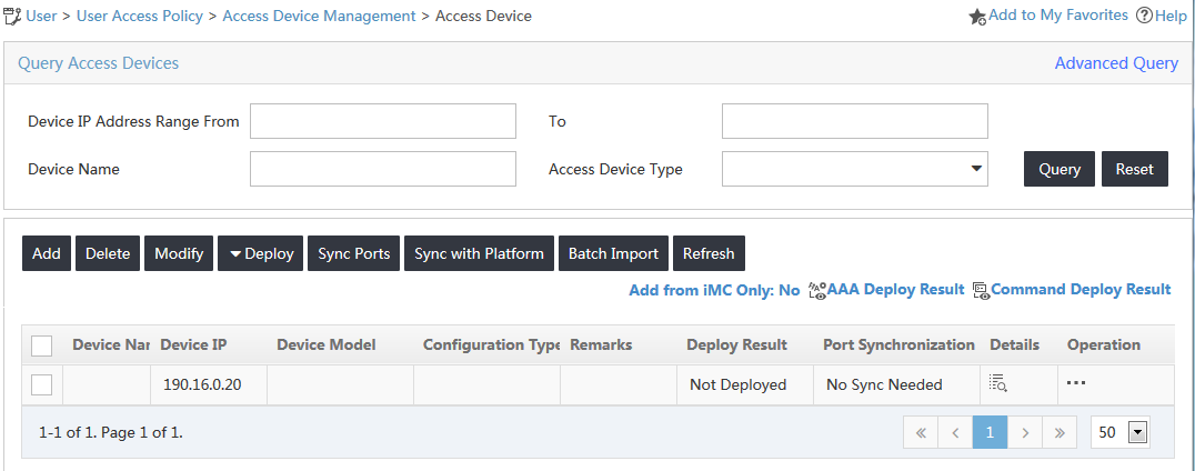
Adding the UAM2 server as an access device
1. Click the User tab.
2. From the navigation tree, select User Access Policy > Access Device Management > Access Device.
The access device list is displayed, as shown in Figure 2.
Figure 2 Accessing the Access Device page
3. Click Add.
The Add Access Device page opens.
4. Configure access information for the access device, as shown in Figure 3:
a. Enter 1812 in the Authentication Port field and 1813 in the Accounting Port field.
b. Select H3C (General) from the Access Device Type list.
c. Enter world in the Shared Key and Confirm Shared Key fields.
d. Use the default values for other parameters.
Figure 3 Adding an access device

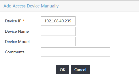
5. You can add an access device manually or by selecting the device from the IMC platform. This example uses the Add Manually option as follows:
a. Click Add Manually in the Device List area.
b. On the Add Access Device Manually page, enter the UAM2 server address 192.168.40.239 in the Device IP field, as shown in Figure 4.
c. Click OK.
Figure 4 Adding an access device manually
6. On the Add Access Device page, click OK.
The Result of Adding Access Devices page opens, as shown in Figure 5.
Figure 5 Viewing the result of adding access devices

Configuring an access policy
1. Click the User tab.
2. From the navigation tree, select User Access Policy > Access Policy.
3. On the access policy list, click Add.
The Add Access Policy page opens.
4. In the Basic Information area, enter roam policy in the Access Policy Name field, as shown in Figure 6.
Figure 6 Adding an access policy
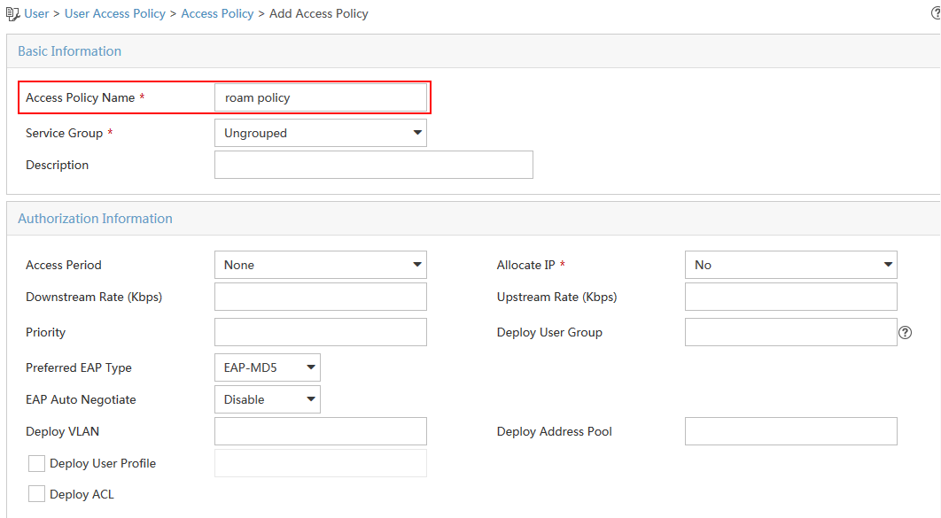
5. Use the default values for other parameters.
6. Click OK.
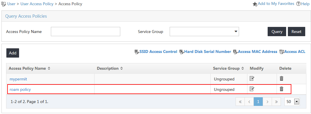
The new access policy is added to the access policy list, as shown in Figure 7.
Figure 7 Viewing the new access policy
Configuring an access service
1. Click the User tab.
2. From the navigation tree, select User Access Policy > Access Service.
3. On the access service list, click Add.
The Add Access Service page opens.
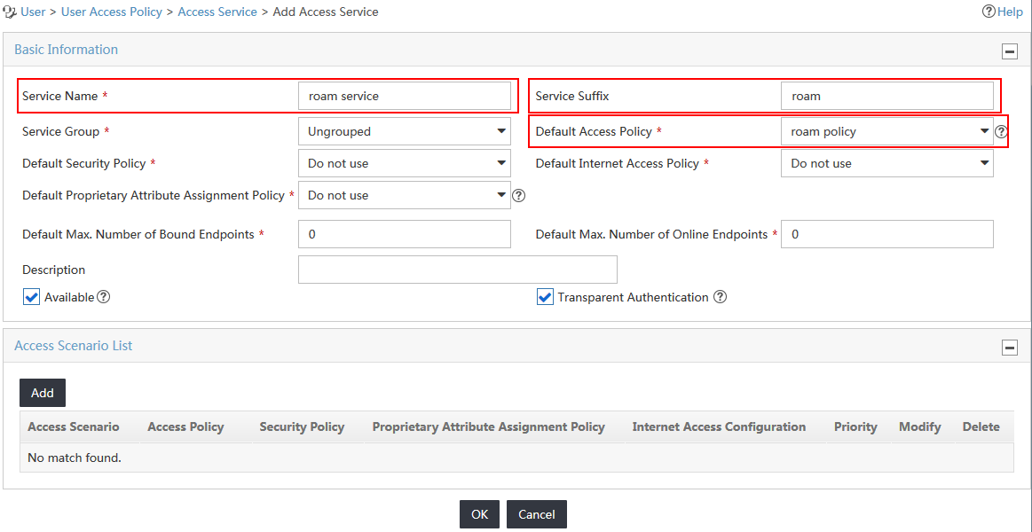
4. Configure basic information for the access service, as shown in Figure 8:
a. Enter roam service in the Service Name field.
b. Enter roam in the Service Suffix field. For more information about determining the service suffix, see Table 1.
c. Select roam policy from the Default Access Policy list.
d. Use the default values for other parameters.
Figure 8 Adding an access service
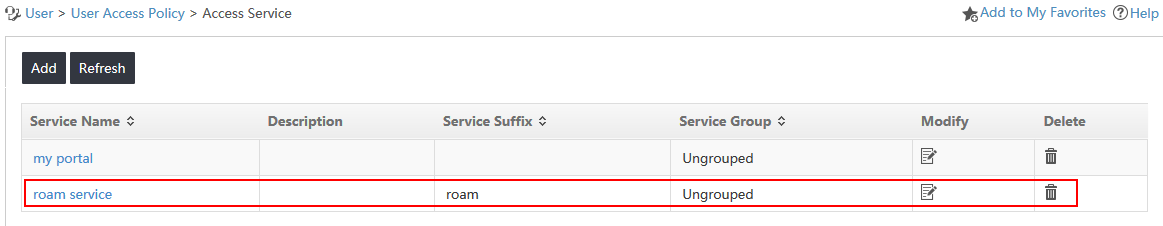
5. Click OK.
The new access service is added to the access service list, as shown in Figure 9.
Figure 9 Viewing the new access service
Configuring an access user and assigning the service to the user
1. Click the User tab.
2. From the navigation tree, select Access User > All Access Users.
3. On the access user list, click Add.
The Add Access User page opens.
4. In the User Name field, click Select to select an existing user account from the IMC Platform, or click Add User to add a new IMC Platform user.
This example uses the Add User option.
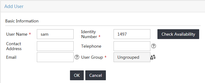
Configure the following parameters, as shown in Figure 10.
a. Enter sam in the User Name field.
b. Enter 1497 in the Identity Number field.
c. Use the default values for other parameters.
d. Click OK.
The Add User page closes.
Figure 10 Adding an access user
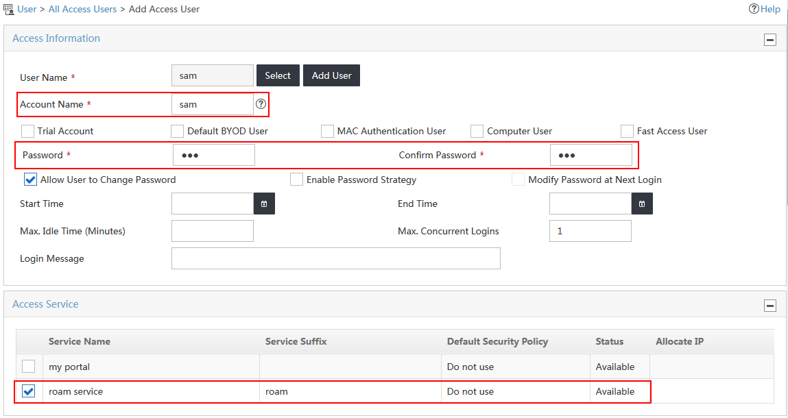
5. On the Add Access User page, configure the following parameters for the access user, as shown in Figure 11:
a. Enter sam in the Account Name field.
b. Enter sam in the Password and Confirm Password fields.
c. Select the access service named roam service from the Access Service list.
d. Use default values for other parameters.
Figure 11 Adding an access user
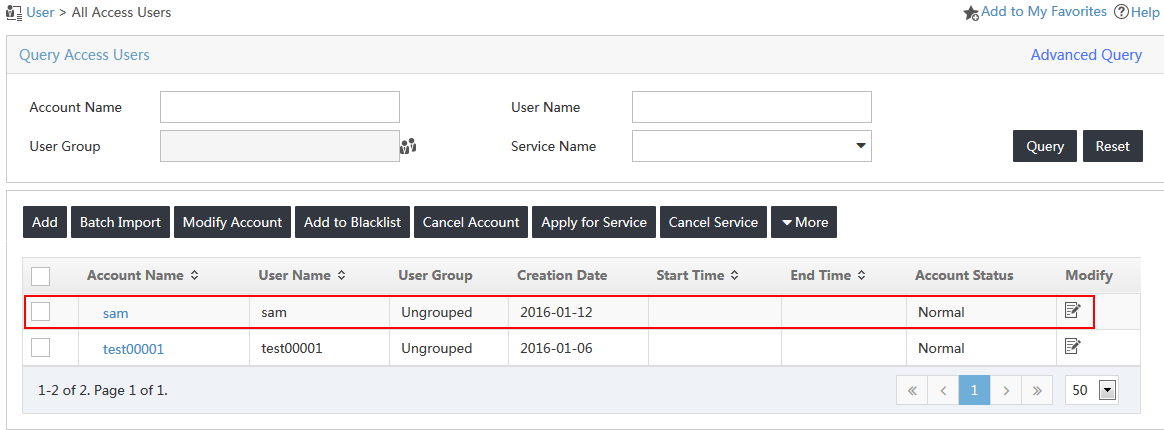
6. Click OK.
The new access user is added to the access user list, as shown in Figure 12.
Figure 12 Viewing the new access user
Configuring UAM2
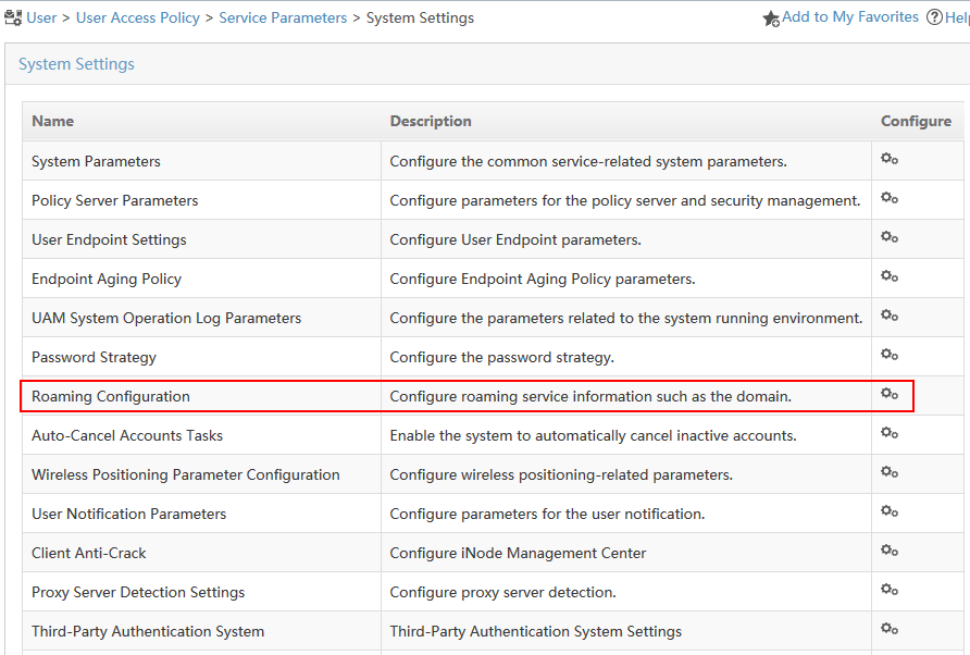
Configuring UAM1 as the destined authentication server
1. Click the User tab.
2. From the navigation tree, select User Access Policy > Service Parameters > System Settings.
The System Settings page opens.
3. Click the Configure icon ![]() for the Roaming Configuration entry, as shown in Figure 13.
for the Roaming Configuration entry, as shown in Figure 13.
Figure 13 Accessing the System Settings page
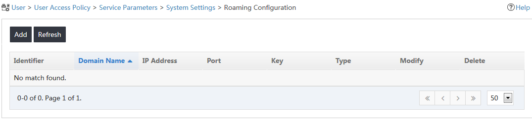
4. On the Roaming Configuration page, click Add, as shown in Figure 14.
Figure 14 Roaming Configuration page
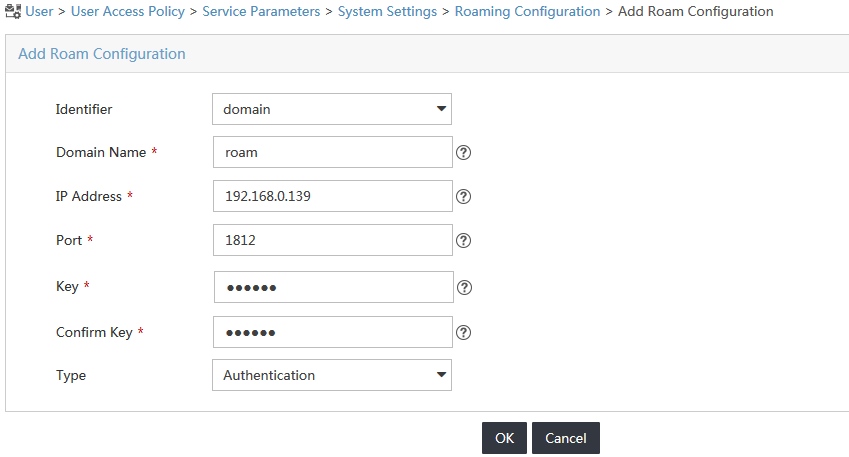
5. On the Add Roaming Configuration page, configure the following parameters for roaming authentication, as shown in Figure 15:
a. Select domain from the Identifier list.
b. Enter roam in the Domain Name field, which must be the same as the service suffix of the access service (roam service) in UAM1.
c. Enter the UAM1 server address 192.168.0.139 in the IP Address field.
d. Enter 1812 in the Port field.
e. Enter world in the Key and Confirm Key fields.
f. Select Authentication from the Type field.
g. Click OK.
Figure 15 Configuring roaming authentication
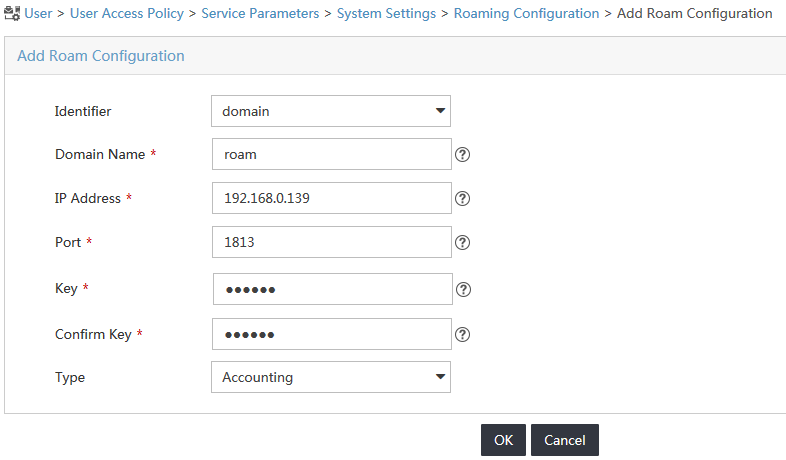
6. On the Roaming Configuration page, click Add.
7. Configure the following parameters for roaming accounting, as shown in Figure 16:
a. Select domain from the Identifier list.
b. Enter roam in the Domain Name field, which must be the same as the service suffix of the access service (roam service) in UAM1.
c. Enter the UAM1 server address 192.168.0.139 in the IP Address field.
d. Enter 1813 in the Port field.
e. Enter world in the Key and Confirm Key fields.
f. Select Accounting from the Type field.
g. Click OK.
Figure 16 Configuring roaming accounting
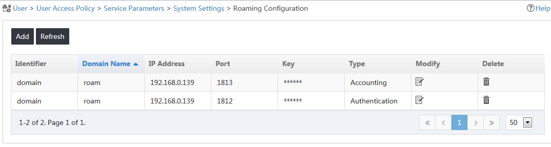
8. Click OK.
The new roaming configuration entries appear in the roaming configuration list, as shown in Figure 17.
Figure 17 Viewing new roaming configuration entries
Adding the switch to UAM2 as an access device
1. Click the User tab.
2. From the navigation tree, select User Access Policy > Access Device Management.
3. On the Access Device Management page, click Access Device.
4. Click Add on top of the access device list.
The Add Access Device page opens, as shown in Figure 18.
Figure 18 Adding an access device

5. In the Access Configuration area, enter hello in the Shared Key and Confirm Shared Key fields. Use the default values for other parameters.
6. Click Add Manually in the Device List area.
The Add Access Device Manually page opens.
7. Enter 192.168.30.100 in the Device IP field, as shown in Figure 19.
Figure 19 Adding an access device manually
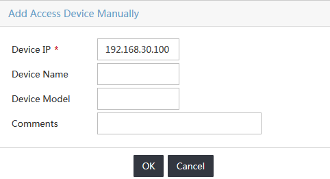
8. Click OK.
The Add Access Device Manually page closes.
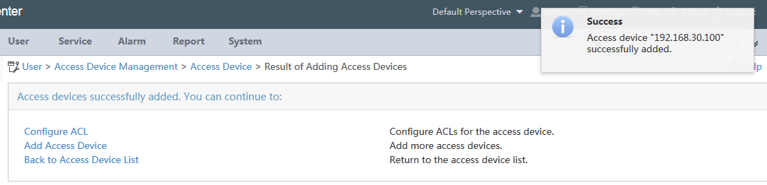
9. On the Add Access Device page, click OK.
The Result of Adding Access Device page opens, as shown in Figure 20.
Figure 20 Viewing the result of adding access devices
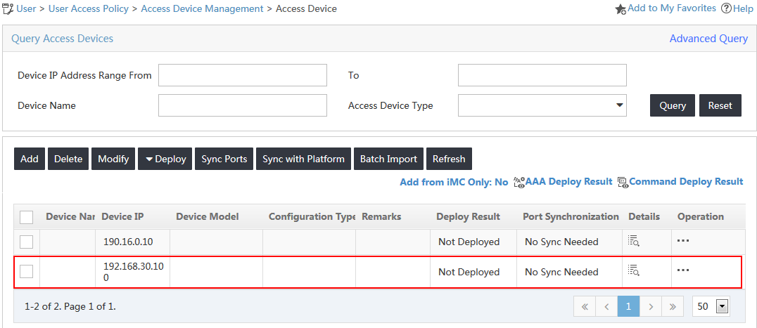
10. Click Back to Access Device List to view the new access device in the Access Device page, as shown in Figure 21.
Figure 21 Viewing the new access device
Configuring the switch
1. Configure a RADIUS scheme:
# Create a RADIUS scheme named 2013.
<H3C>system-view
System View: return to User View with Ctrl+Z.
[H3C]radius scheme 2013
# Configure UAM1 as the primary RADIUS authentication and accounting server. Set the RADIUS authentication port to 1812 and accounting port 1813.
[H3C-radius-2013]primary authentication 192.168.40.239 1812
[H3C-radius-2013]primary accounting 192.168.40.239 1813
# Configure the shared key to hello to secure RADIUS authentication and accounting communication.
[H3C-radius-2013]key authentication hello
[H3C-radius-2013]key accounting hello
# Specify the RADIUS server type as extended to support UAM.
[H3C-radius-2013] server-type extended
# Configure the switch to include domain information in the user names that are sent to the RADIUS server.
[H3C-radius-2013]user-name-format with-domain
[H3C-radius-2013]quit
2. Create an ISP domain:
# Create an ISP domain named roam.
[H3C]domain roam
# Configure the switch to use the RADIUS scheme 2013 for 802.1X users.
[H3C-isp-roam]authentication lan-access radius-scheme 2013
[H3C-isp-roam]authorization lan-access radius-scheme 2013
[H3C-isp-roam]accounting lan-access radius-scheme 2013
[H3C-isp-roam]quit
3. Configure 802.1X authentication:
# Enable 802.1X globally and on Ethernet 1/0/1. The 802.1X function takes effect on the interface only when 802.1X is enabled globally and on the interface.
[H3C]dot1x
[H3C]dot1x interface Ethernet 1/0/1
# Configure the switch to perform EAP termination and support all CHAP authentication methods for RADIUS communication.
[H3C]dot1x authentication-method chap
Verifying the configuration
Triggering 802.1X authentication
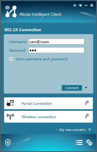
1. On the iNode client, click 802.1X Connection.
The 802.1X Connection window opens.
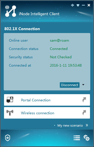
2. Enter the username and password, and click Connect, as shown in Figure 22.
Figure 22 Viewing the 802.1X connection
The authentication process starts. The authentication result shows that the connection has been established, as shown in Figure 23.
Figure 23 Viewing the authentication result
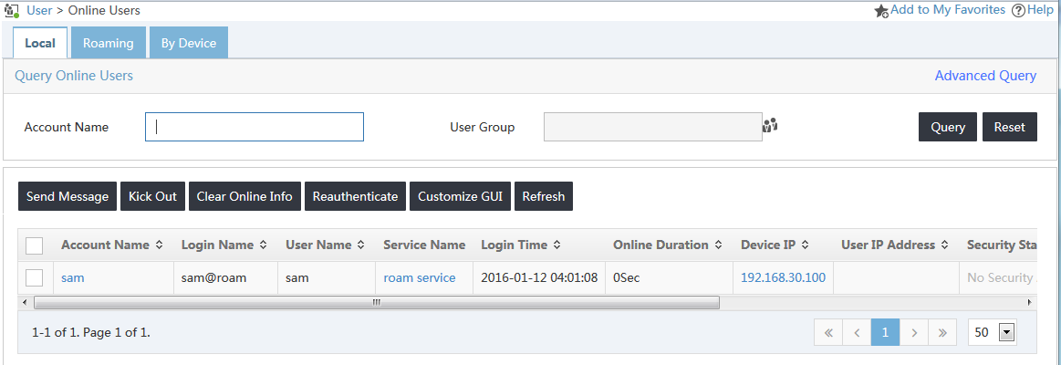
Viewing online users in UAM1
1. Click the User tab.
2. From the navigation tree, select Access User > Online Users.
3. Click the Local tab.
4. Verify that the user named sam opens in the local online user list, as shown in Figure 24.
Figure 24 Viewing the local user
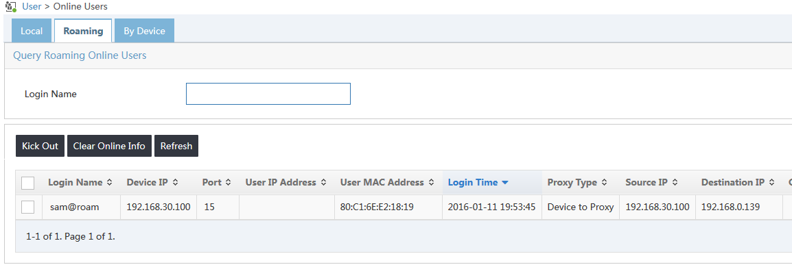
Viewing online users in UAM2
1. Click the User tab.
2. From the navigation tree, select Access User > Online Users.
3. Click the Roaming tab.
4. Verify that the user named sam@roam has been added to the roaming online user list, as shown in Figure 25. The destination IP address is the UAM1 server address on the visited network.
Figure 25 Viewing the roaming user