18-H3C IMC UAM Portal Authentication with the iNode Client Configuration Examples-book.pdf(860.91 KB)
- Released At: 05-07-2024
- Page Views:
- Downloads:
- Related Documents
-
|
H3C IMC UAM |
|
Portal Authentication with The iNode Client Configuration Examples |
|
|
Software version: IMC UAM 7.2 (E0403)
|
Copyright © 2016 Hangzhou H3C Technologies Co., Ltd. All rights reserved. No part of this manual may be reproduced or transmitted in any form or by any means without prior written consent of Hangzhou H3C Technologies Co., Ltd. The information in this document is subject to change without notice. |
|
Contents
Example: Using the iNode client for portal authentication
Associating an access service with the access policy
Configuring the portal service
Introduction
This document provides examples for configuring portal to authenticate users by using the iNode client.
The examples apply to enterprise networks and campus networks that are configured with portal authentication.
Prerequisites
Make sure the access device supports portal.
Example: Using the iNode client for portal authentication
Network configuration
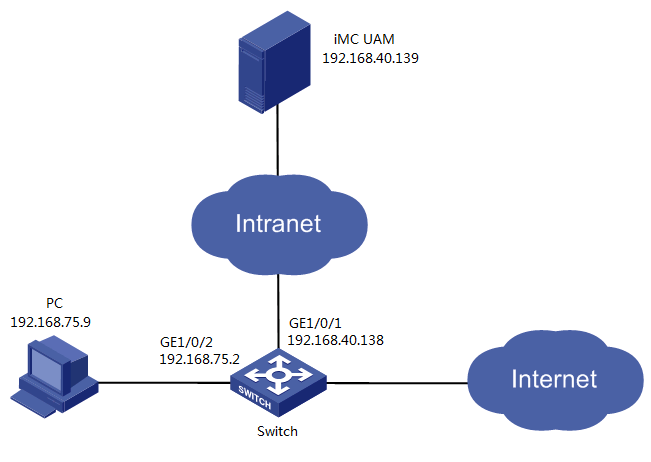
As shown in Figure 1, UAM acts as a portal server. UAM works with the iNode client to authenticate endpoint users.
The account name test is used to access the network through the iNode client on a Windows PC.
The switch manages the portal user in an ISP domain named portal and includes the domain name in the usernames that are sent for authentication.
· Set the shared keys for secure RADIUS communication to movie, and set the ports for authentication and accounting to 1812 and 1813, respectively.
· Set the shared key for secure portal communication to expert.
Software versions used
This configuration example was created and verified on the following platforms:
· IMC UAM 7.2 (E0403)
· H3C S5820V2-54QS-GE Comware Software, Version 7.1.045, ESS 2415
· iNode PC 7.2 (E0403)
Restrictions and guidelines
When you configure an access device or an access service in UAM, follow these restrictions and guidelines:
· Make sure the shared key you configure for the access device in UAM is the same as the CLI configuration on the switch.
· Make sure the authentication and accounting port numbers you configure for the access device in UAM are the same as the CLI configuration on the switch.
· Make sure the service type ID is the same as the suffix of the service assigned to the access user test.
· Make sure the shared key for secure portal communication you configure in UAM is the same as the configuration on the switch.
· Configure the device IP address for the access device by using one of the following methods:
¡ If you have configured the nas-ip command for the RADIUS scheme on the switch, configure the NAS IP as the access device IP address in UAM.
¡ If you do not configure the nas-ip command for the RADIUS scheme, enter the IP address of the device's interface that connects to UAM for the access device.
· Configure a service suffix for the portal user depending on the authentication domain and username format settings on the switch, as shown in Table 1.
Table 1 Determining the service suffix
|
Username in iNode |
Authentication domain on the switch |
Username format command on the switch |
Service suffix in UAM |
|
test@portal |
portal |
user-name-format with-domain |
portal |
|
user-name-format without-domain |
No suffix |
Configuring UAM
Adding the switch to UAM
1. Click the User tab.
2. From the navigation tree, select User Access Policy > Access Device Management > Access Device.
The access device list is displayed, as shown in Figure 2.
Figure 2 Accessing the Access Device page
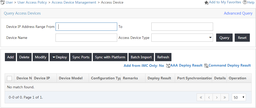
3. On the access device list, click Add.
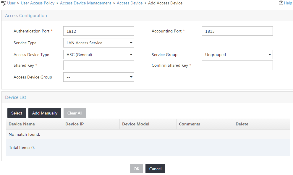
The Add Access Device page opens, as shown in Figure 3.
Figure 3 Adding an access device
4. Add the switch to UAM as an access device.
You can add a device to UAM either manually or by selecting the device from the IMC platform. This example uses the Add Manually option.
To add an access device manually:
a. Click Add Manually.
The Add Access Device Manually page opens.
b. Enter 192.168.75.2 in the Device IP field, as shown in Figure 4.
Figure 4 Manually adding an access device
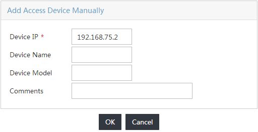
c. Click OK to return to the Add Access Device page.
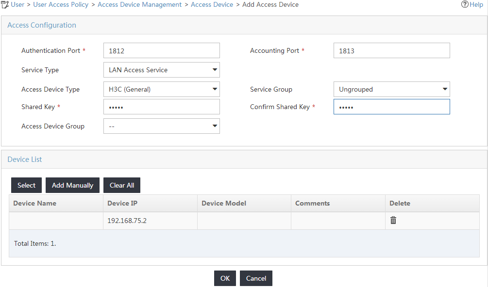
5. Configure access information for the access device, as shown in Figure 5:
a. Enter 1812 in the Authentication Port field and 1813 in the Accounting Port field.
b. Select H3C (General) from the Access Device Type list.
c. Enter movie in the Shared Key and Confirm Shared Key fields.
d. Use the default values for other parameters.
Figure 5 Configuring the access device
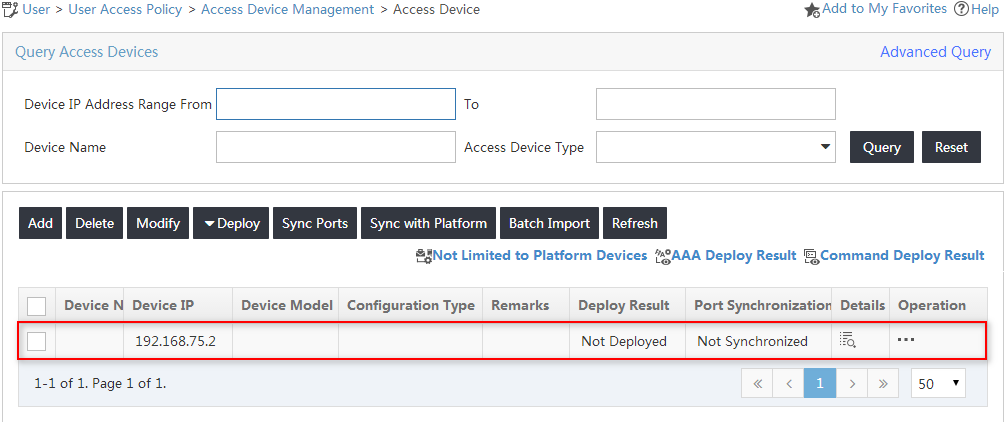
6. Click OK.
On the page that opens, click the Back to Access Device List link to view the added access device in the access device list, as shown in Figure 6.
Figure 6 Viewing the new access device
Configuring an access policy
1. Click the User tab.
2. From the navigation tree, select User Access Policy > Access Policy.
The access policy list is displayed, as shown in Figure 7.
Figure 7 Accessing the Access Policy page
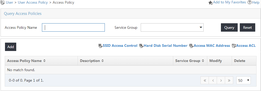
3. On the access policy list, click Add.
The Add Access Policy page opens.
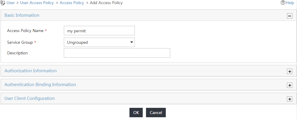
4. Configure the access policy parameters, as shown in Figure 8:
a. Enter my permit in the Access Policy Name field.
b. Use the default values for other parameters.
Figure 8 Adding an access policy
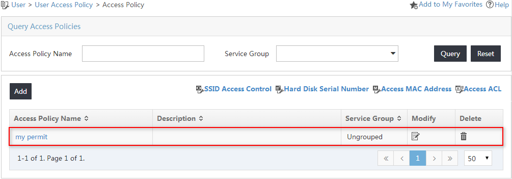
5. Click OK.
The new access policy named my permit is added to the access policy list, as shown in Figure 9.
Figure 9 Viewing the new access policy
Associating an access service with the access policy
1. Click the User tab.
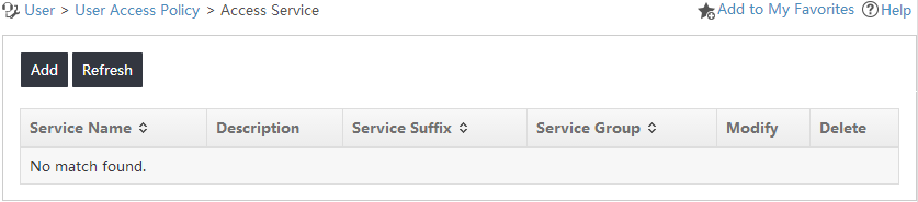
2. From the navigation tree, select User Access Policy > Access Service.
The access service list is displayed, as shown in Figure 10.
Figure 10 Accessing the access service list
3. On the access service list, click Add.
The Add Access Service page opens.
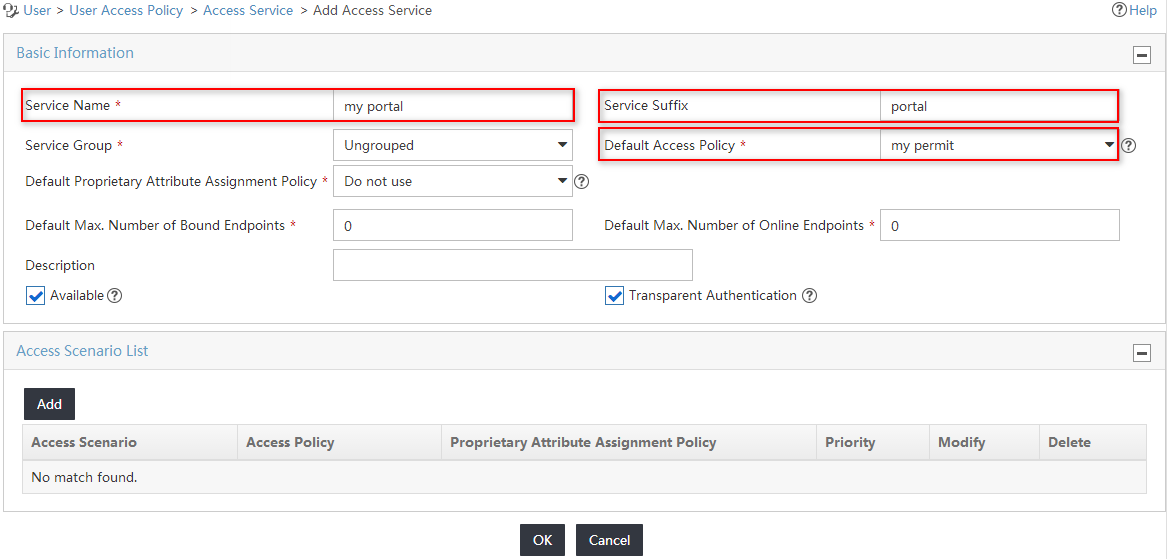
4. Configure basic information for the access service, as shown in Figure 11:
a. Enter my portal in the Service Name field.
b. Enter portal in the Service Suffix field. For more information about determining the service suffix, see Table 1.
c. Select my permit from the Default Access Policy list.
d. Use the default values for other parameters.
Figure 11 Adding an access service
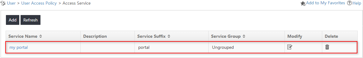
5. Click OK.
The new access service named my portal is added to the access service list, as shown in Figure 12.
Figure 12 Viewing the new access service
Configuring an access user
1. Click the User tab.
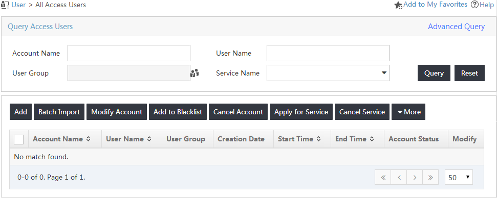
2. From the navigation tree, select Access User > All Access Users.
The All Access Users page opens, as shown in Figure 13.
Figure 13 Accessing the access user list
3. On the access user list, click Add.
The Add Access User page opens.
4. In the User Name field, click Select to select an existing user account from the IMC Platform, or click Add User to add a new IMC Platform user.
This example uses the Add User option.
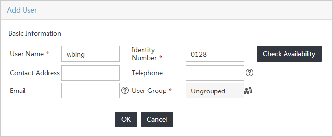
Configure the following parameters, as shown in Figure 14.
a. Enter wbing in the User Name field.
b. Enter 0128 in the Identity Number field.
c. Use the default values for other parameters.
d. Click OK.
The Add User page closes.
Figure 14 Adding a new IMC platform user
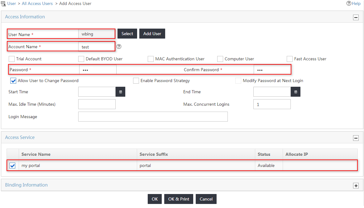
5. On the Add Access User page, configure the following parameters for the access user, as shown in Figure 15:
a. Enter test in the Account Name field.
b. Enter 123 in the Password and Confirm Password fields.
c. Select the service named my portal from the Access Service list.
d. Use the default values for other parameters.
Figure 15 Configuring an access user
6. Click OK.
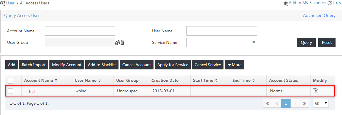
The new access user named test is added to the access user list, as shown in Figure 16.
Figure 16 Viewing the new access user
Configuring the portal service
Configuring UAM as the portal server
1. Click the User tab.
2. From the navigation tree, select User Access Policy > Portal Service > Server.
The Server page opens.
3. On the Service Type List area, click Add, as shown in Figure 17.
The Add Service Type page opens.
Figure 17 Accessing the Server page

4. Configure the service type parameters, as shown in Figure 18:
a. Enter portal in the Service Type ID field.
b. Enter office in the Service Type field.
Figure 18 Adding a service type

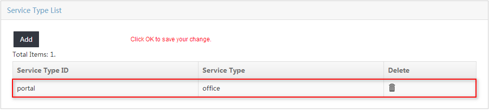
5. Click OK.
The new service type named portal is added to the service type list, as shown in Figure 19.
Figure 19 Viewing the new service type
6. Use default values for other parameters.
7. Click OK.
Configuring an IP group
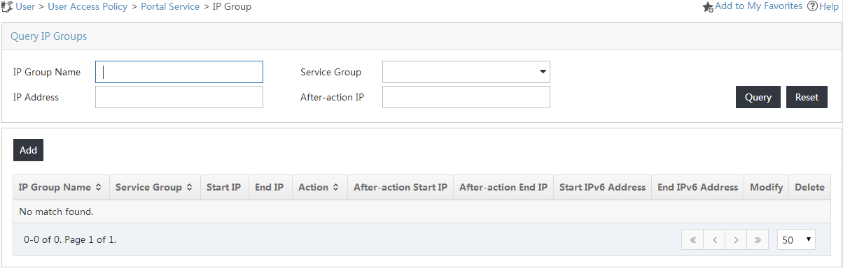
1. Click the User tab.
2. From the navigation tree, select User Access Policy > Portal Service > IP Group.
The IP Group page opens, as shown in Figure 20.
Figure 20 Accessing the IP Group page
3. On the IP group list, click Add.
The Add IP Group page opens.
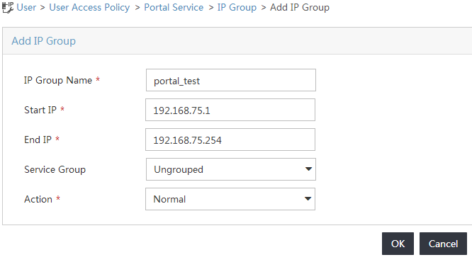
4. Configure the IP group parameters, as shown in Figure 21:
a. Enter portal_test in the IP Group Name field.
b. Enter 192.168.75.1 in the Start IP field.
c. Enter 192.168.75.254 in the End IP field.
The IP address of the PC running the iNode client must be included in this IP segment.
Figure 21 Adding an IP group
5. Click OK.
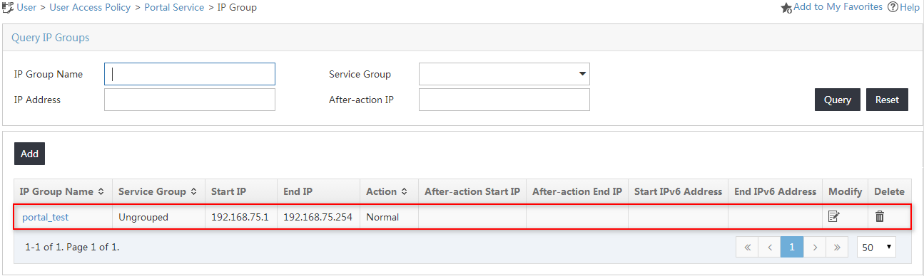
The new IP group named portal_test is added to the IP group list, as shown in Figure 22.
Figure 22 Viewing the new IP group
Configuring the switch as a portal device
1. Click the User tab.
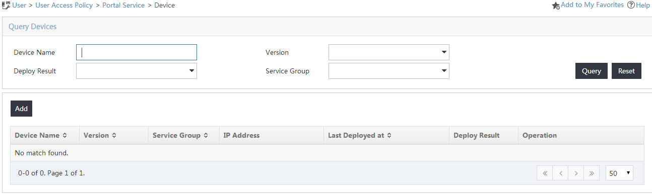
2. From the navigation tree, select User Access Policy > Portal Service > Device.
The Device page opens, as shown in Figure 23.
Figure 23 Accessing the Device page
3. On the device list, click Add.
The Add Device page opens.
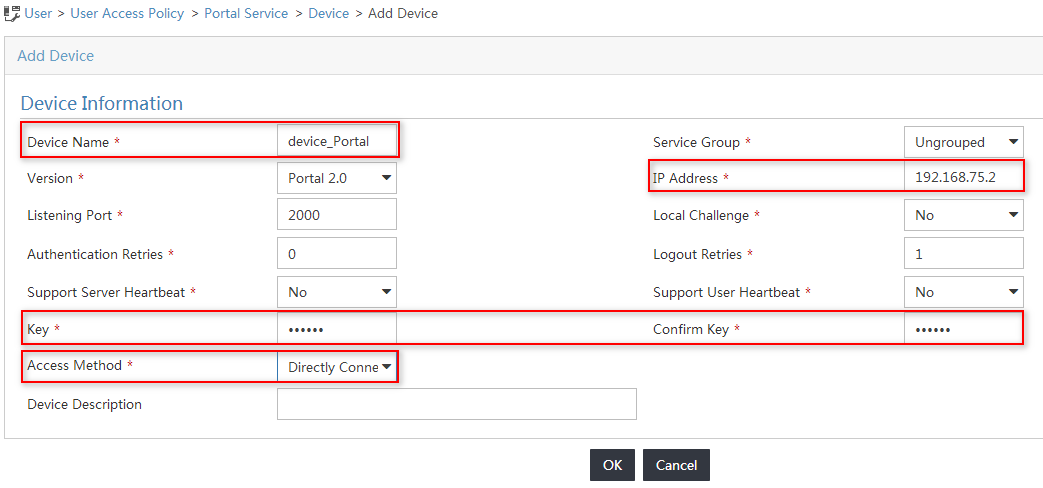
4. Configure the portal device parameters, as shown in Figure 24:
a. Enter device_Portal in the Device Name field.
b. Enter the switch's IP address 192.168.75.2 in the IP Address field.
c. Enter expert in the Key and Confirm Key fields.
d. Select Directly Connected from the Access Method list.
e. Use the default values for other parameters.
Figure 24 Configuring a portal device
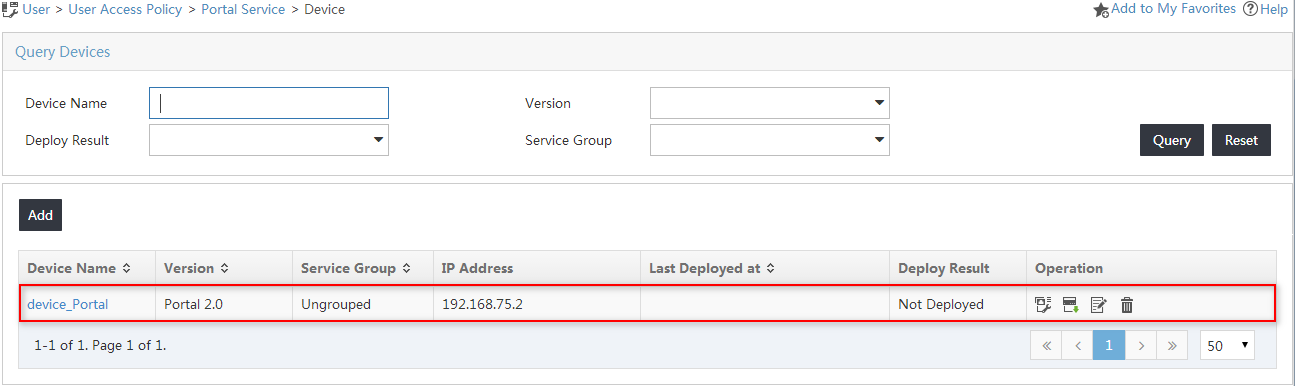
5. Click OK.
The new portal device named device_Portal is added to the portal device list, as shown in Figure 25.
Figure 25 Viewing the new portal device
Configuring a port group
1. In the portal device list, click the Port Group icon ![]() in the Operation column
for device_Portal.
in the Operation column
for device_Portal.
The Configure Port Group page opens.
2. On the port group list, click Add.
The Add Port Group page opens.
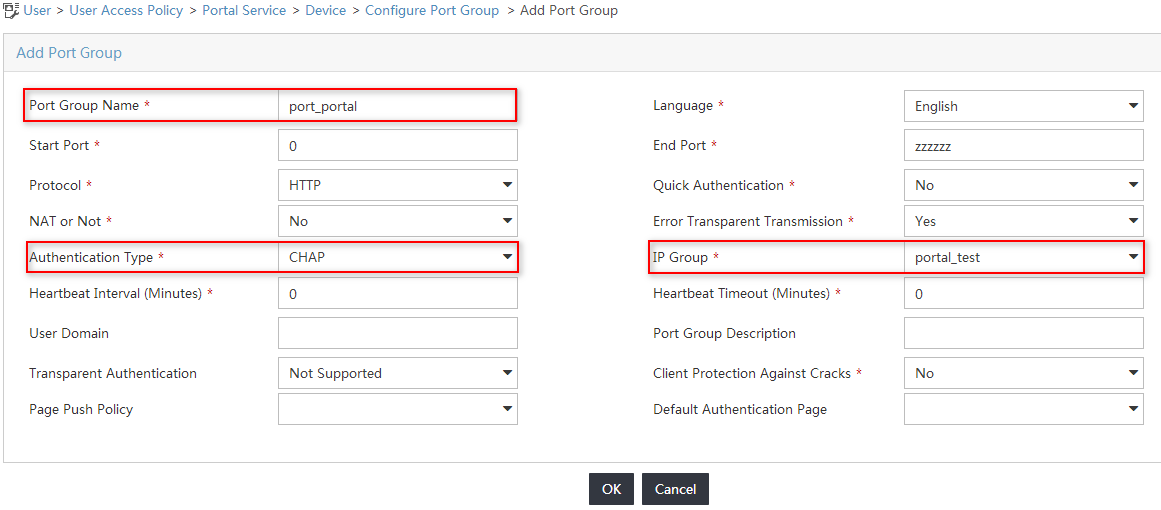
3. Configure the port group parameters, as shown in Figure 26:
a. Enter port_portal in the Port Group Name field.
b. Select CHAP from the Authentication Type list.
c. Select portal_test from the IP Group list.
d. Use the default values for other parameters.
Figure 26 Configuring a port group
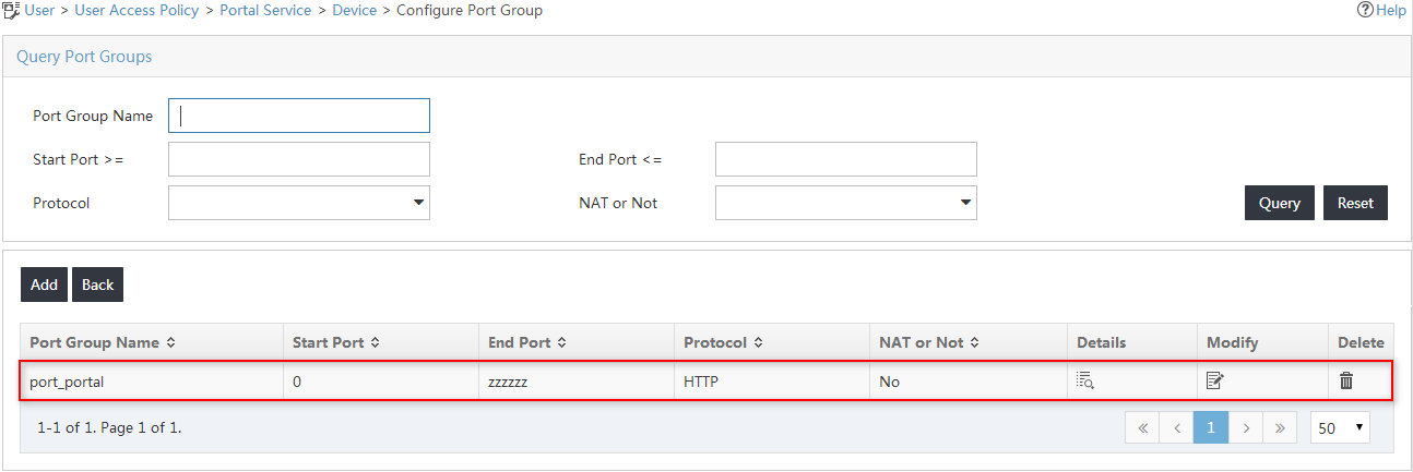
4. Click OK.
The new port group named port_portal is added to the port group list, as shown in Figure 27.
Figure 27 Viewing the new port group
Configuring the switch
1. Configure a RADIUS scheme:
# Create a RADIUS scheme named allpermit.
<H3C>system-view
System View: return to User View with Ctrl+Z.
[Device]radius scheme allpermit
New Radius scheme
# Configure UAM as the primary RADIUS authentication and accounting servers in the scheme, and set the RADIUS authentication port and accounting port to 1812 and 1813, respectively.
[Device-radius-allpermit]primary authentication 192.168.40.139 1812
[Device-radius-allpermit]primary accounting 192.168.40.139 1813
# Configure the shared key to movie to secure RADIUS authentication and accounting communication.
[Device-radius-allpermit]key authentication simple movie
[Device-radius-allpermit]key accounting simple movie
# Configure the switch to include domain information in the user names to be sent to the RADIUS server.
[Device-radius-allpermit]user-name-format with-domain
[Device-radius-allpermit]nas-ip 192.168.75.2
[Device-radius-allpermit]quit
2. Configure an ISP domain:
# Add an ISP domain named portal.
[Device]domain portal
New Domain added.
# Configure the switch to use the RADIUS scheme allpermit for portal users in the ISP domain.
[Device-isp-portal]authentication portal radius-scheme allpermit
[Device-isp-portal]authorization portal radius-scheme allpermit
[Device-isp-portal]accounting portal radius-scheme allpermit
[Device-isp-portal]quit
3. Configure portal authentication:
# Configure UAM as the portal server named myportal, and configure the key for portal communication.
[Device]portal server myportal
[Device-portal-server-myportal]ip 192.168.40.139 key simple expert
[Device-portal-server-myportal]quit
# Specify the redirection URL for the portal Web server.
[Device]portal web-server myportal
[Device-portal-websvr-myportal]url http://192.168.40.139:8080/portal
[Device-portal-websvr-myportal]quit
# Enable direct portal authentication on GigabitEthernet 1/0/2.
[Device]interface gigabitethernet 1/0/2
[Device-gigabitethernet1/0/2]portal enable method direct
# Specify the portal Web server myportal on GigabitEthernet 1/0/2.
[Device-gigabitethernet1/0/2] portal apply web-server myportal
# Configure the BAS-IP attribute as 192.168.75.2 for portal packets sent from GigabitEthernet 1/0/2 to the portal authentication server.
[Device-gigabitethernet1/0/2]portal bas-ip 192.168.75.2
[Device-gigabitethernet1/0/2]quit
Verifying the configuration
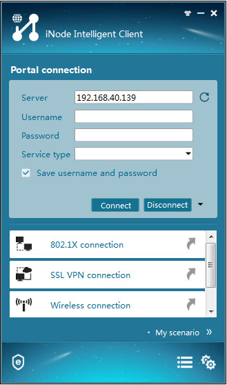
1. On the iNode client, click Portal Connection.
The Portal Connection window opens.
2. Click the Refresh icon ![]() next
to the Server field to obtain the IP address of the portal server, as shown in Figure 28.
next
to the Server field to obtain the IP address of the portal server, as shown in Figure 28.
Figure 28 Obtaining the portal server IP address
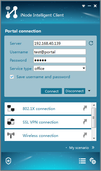
3. Enter the username and password, select office from the Service type field, and click Connect, as shown in Figure 29.
Figure 29 Triggering portal authentication
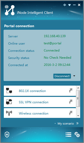
The authentication process starts. The authentication result shows that the connection has been established, as shown in Figure 30.
Figure 30 Viewing the authentication result