- Released At: 05-07-2024
- Page Views:
- Downloads:
- Related Documents
-
|
H3C IMC UAM |
|
Portal Authentication Using iNode DC Configuration Examples |
|
|
Software version: IMC UAM 7.0 (E0103)
|
Copyright © 2016 Hangzhou H3C Technologies Co., Ltd. All rights reserved. No part of this manual may be reproduced or transmitted in any form or by any means without prior written consent of Hangzhou H3C Technologies Co., Ltd. The information in this document is subject to change without notice. |
|
Contents
Example: Configuring portal authentication using the iNode DC
Configuring the portal service
Triggering portal authentication
Introduction
This document provides examples for configuring portal authentication that uses the iNode dissolvable client (iNode DC).
The examples apply to a network that provides access for guests. A guest does not need to install the iNode PC client for authentication. Instead, the guest uses a Web browser to trigger portal authentication, and the iNode DC plugin is automatically downloaded on the guest's PC.
The iNode DC supports only portal authentication and can implement security check on PCs.
Prerequisites
Make sure the access device supports portal.
Example: Configuring portal authentication using the iNode DC
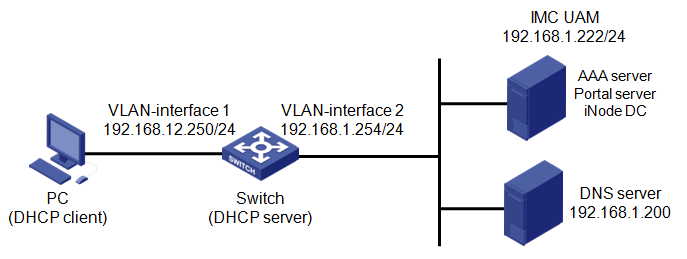
Network configuration
As shown in Figure 1, implement portal authentication and security check on guests who access the network. Detailed requirements are as follows:
· A guest uses the iNode DC to perform portal authentication and security check. The guest accesses the network by using an account named test01 and a DHCP-assigned IP address.
· The switch serves as the portal access device and DHCP server. The access device manages the portal user in an ISP domain named kkk and includes the domain name in the usernames that are sent to UAM for authentication.
· UAM serves as the portal and AAA server. UAM deploys the iNode DC to the PC and checks the sharing settings on the PC.
· The access device and UAM use the shared key expert for secure RADIUS communication, and use port 1812 for authentication and port 1813 for accounting.
· The access device and UAM use the key world for portal communication. The redirection URL of the portal server is http://192.168.1.222:8080/portal.
Software versions used
This configuration example was created and verified on the following platforms:
· IMC UAM 7.0 (E0103)
· HP 5500-48G-PoE+-EI-2SLOT Comware Software, Version 5.20
· iNode DC 7.0 (E0103)
Restrictions and guidelines
When you configure portal authentication that uses the iNode DC, follow these restrictions and guidelines:
· Java Runtime Environment is required to use the iNode DC. When you are prompted to install Java Runtime Environment after submitting your account information, follow the instructions to download and install the software.
· Guidelines for configuring an IP group on UAM:
¡ For an IP group, the end IP address cannot be lower than the start IP address.
¡ The IP addresses in two IP groups cannot overlap.
· Guidelines for configuring a portal device on UAM:
¡ When you configure the IP address of a Comware V5 device, use the IP address of the access device interface connected to the PC.
¡ If you set the access method to Directly Connected, an unauthenticated user can access only the portal server and authentication-free network resources. After authentication, the user can access the network resources for authenticated users.
· The portal redirection URL and communication key configured on UAM must be the same as those configured for the portal server on the access device.
· The RADIUS port and shared key settings configured on UAM must be the same as those configured on the access device.
· Configure a service suffix for the guest user depending on the authentication domain and username format settings on the switch, as shown in Table 1.
Table 1 Determining the service suffix
|
Authentication username |
Authentication domain on the switch |
Username format command on the switch |
Service suffix in UAM |
|
test01@kkk |
kkk |
user-name-format with-domain |
kkk |
|
user-name-format without-domain |
No suffix |
Configuring UAM
Configuring the portal service
Configuring a portal server
1. Click the User tab.
2. From the navigation tree, select User Access Policy > Portal Service > Server.
The Server page opens, as shown in Figure 2.
3. Configure a portal server:
a. In the Service Type List, click Add.
b. Enter kkk in the Service Type ID field and workgroup in the Service Type field.
The service type ID must be the same as the service suffix in the access service. A portal user can choose the configured service type on the IMC portal login page.
c. Click OK.
d. Use the default values for other parameters, as shown in Figure 2.
Figure 2 Configuring a portal server
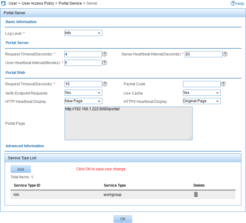
4. Click OK.
Configuring an IP group
1. From the navigation tree, select User Access Policy > Portal Service > IP Group.
2. Click Add.
The Add IP Group page opens, as shown in Figure 3.
3. Configure an IP group:
a. Enter iplist_dc in the IP Group Name field.
b. Enter 192.168.12.2 in the Start IP field.
c. Enter 192.168.12.200 in the End IP field.
d. Use the default values for other parameters.
Figure 3 Configuring an IP group
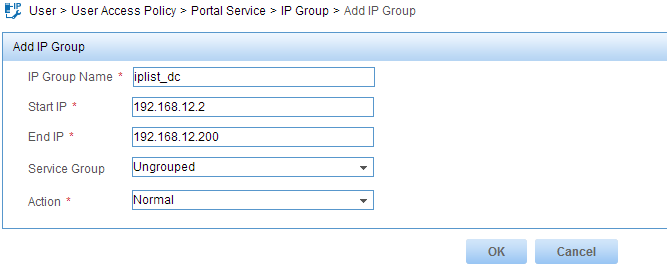
4. Click OK.
Configuring a portal device
1. From the navigation tree, select User Access Policy > Portal Service > Device.
2. Click Add.
The Add Device page opens, as shown in Figure 4.
3. Configure a portal device:
a. Enter device_dc in the Device Name field.
b. Enter 192.168.12.250 in the IP Address field.
c. Enter world in the Key and Confirm Key fields.
d. Select Directly Connected from the Access Method list.
e. Use the default values for other parameters.
Figure 4 Configuring a portal device
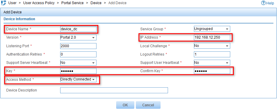
4. Click OK.
The portal device is added to the portal device list, as shown in Figure 5.
Figure 5 Viewing the portal device
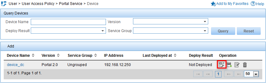
5. In the portal device list, click the Port Group icon ![]() in the Operation column
for the device device_dc.
in the Operation column
for the device device_dc.
6. Click Add.
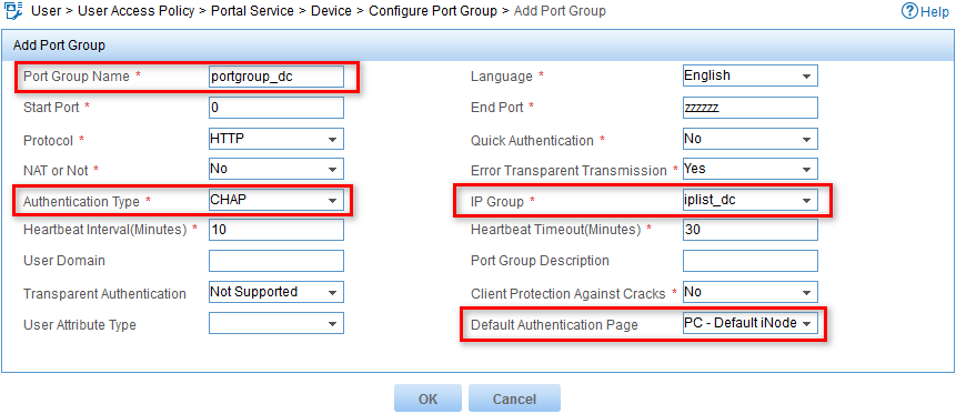
The Add Port Group page opens, as shown in Figure 6.
7. Configure a port group:
a. Enter portgroup_dc in the Port Group Name field.
b. Select CHAP from the Authentication Type list.
c. Select iplist_dc from the IP Group list.
d. Select PC-Default iNode DC Login(PC) from the Default Authentication Page list.
e. Use the default values for other parameters.
Figure 6 Configuring a port group
Configuring an access device
1. From the navigation tree, select User Access Policy > Access Device Management > Access Device.
2. Click Add.
The Add Access Device page opens, as shown in Figure 7.
Figure 7 Configuring an access device
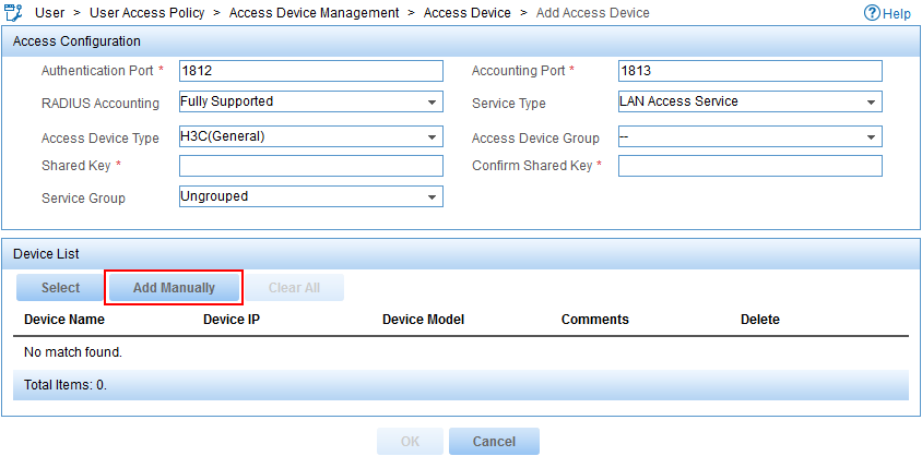
3. Add an access device.
You can select an access device from the IMC Platform or add an access device manually. This example uses the manual method.
To add an access device manually:
a. In the Device List, click Add Manually.
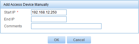
b. Enter the IP address of the access device in the Start IP field, as shown in Figure 8.
This example uses 192.168.12.250.
Figure 8 Adding an access device manually
c. Click OK.
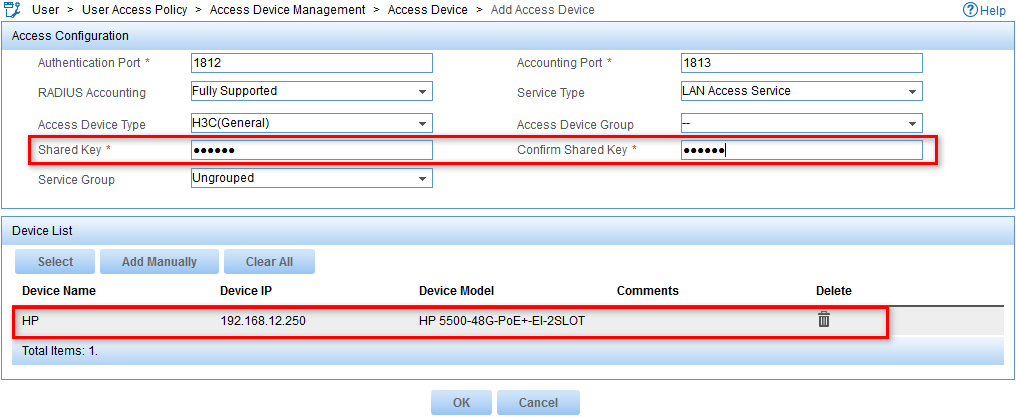
4. Configure the parameters in the Access Configuration area, as shown in Figure 9:
a. Enter expert in the Shared Key and Confirm Shared Key fields.
b. Use the default values for other parameters.
Figure 9 Configuring Access Configuration parameters
Configuring an access policy
This example configures an access policy that does not implement access control. The access policy is used for the access service configuration.
To configure an access policy:
1. Click the User tab.
2. From the navigation tree, select User Access Policy > Access Policy.
3. Click Add.
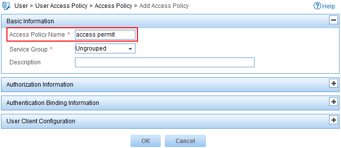
The Add Access Policy page opens, as shown in Figure 10.
4. Configure an access policy:
a. Enter access permit in the Access Policy Name field.
b. Use the default values for other parameters.
Figure 10 Configuring an access policy
5. Click OK.
Configuring a security policy
Configuring a share control policy
1. From the navigation tree, select User Security Policy > Share Control.
2. Click Add.
The Add Share Control page opens, as shown in Figure 11.
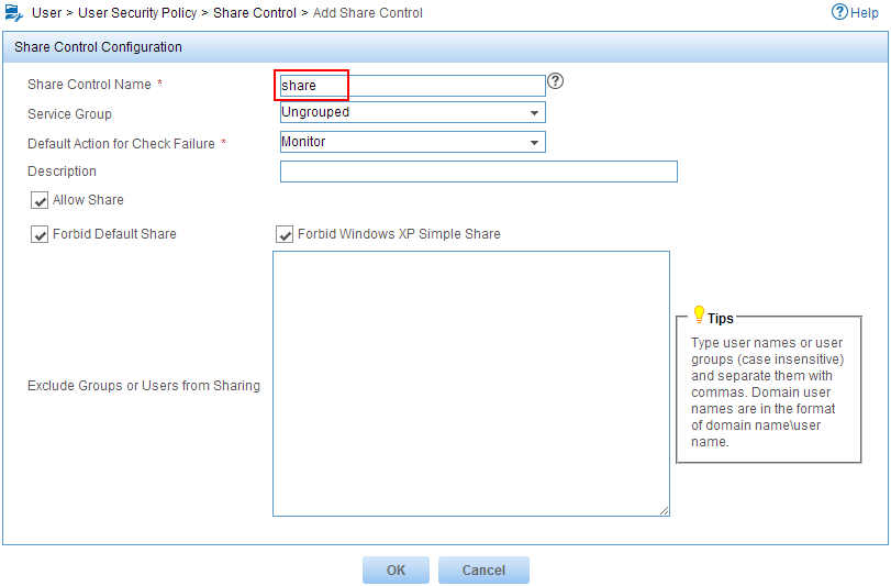
3. Configure a share control policy:
a. Enter share in the Share Control Name field.
b. Select Forbid Default Share and Forbid Windows XP Simple Share.
c. Use the default values for other parameters.
Figure 11 Configuring a share control policy
4. Click OK.
Configuring a security policy
1. From the navigation tree, select User Security Policy > Security Policy.
2. Click Add.
The Add Security Policy page opens, as shown in Figure 12.
3. Configure a security policy:
a. Enter sec-policy in the Policy Name field.
b. In the Share Control area, select the Check Share option and select share from the Share Control list.
Figure 12 Configuring a security policy
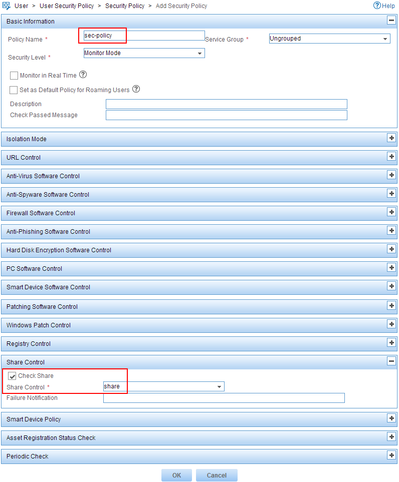
4. Click OK.
Configuring an access service
1. From the navigation tree, select User Access Policy > Access Service.
2. Click Add.
The Add Access Service page opens, as shown in Figure 13.
3. Configure an access service:
a. Enter dc-service in the Service Name field.
b. Enter kkk in the Service Suffix field. For more information about determining the service suffix, see Table 1.
c. Select access permit from the Default Access Policy list.
d. Select sec-policy from the Default Security Policy list.
e. Use the default values for other parameters.
Figure 13 Configuring an access service
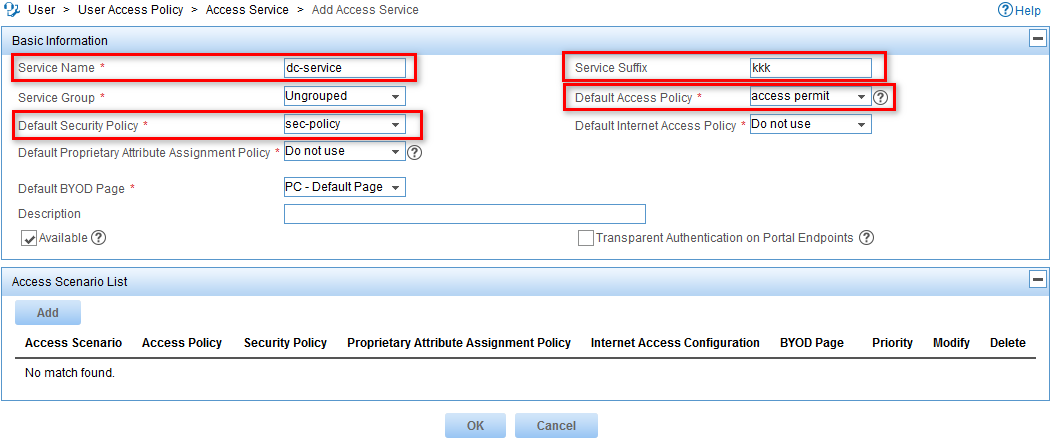
4. Click OK.
Configuring an access user
1. From the navigation tree, select Access User > All Access Users.
2. Click Add.
The Add Access User page opens.
3. Add an access user manually or select a user from the IMC Platform. This example uses the manual method.
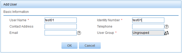
a. Click Add User for the User Name field, as shown in Figure 14.

b. Enter test01 in the User Name field and Identify Number field, as shown in Figure 15.
c. Click OK.
Figure 15 Configuring user information
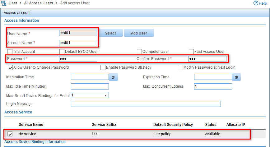
4. Configure an access account, as shown in Figure 16:
a. Enter test01 in the Account Name field.
b. Enter 123 in the Password and Confirm Password fields.
c. Select dc-service in the Access Service list.
Figure 16 Configuring a user account
Configuring the switch
1. Configure a RADIUS scheme:
# Create RADIUS scheme auth_dc.
[AccessDev]radius scheme auth_dc
# Configure UAM as the authentication and accounting server.
[AccessDev-radius-auth_dc]primary authentication 192.168.1.222 1812
[AccessDev-radius-auth_dc]primary accounting 192.168.1.222 1813
# Set the shared key to expert for authentication and accounting communication.
[AccessDev-radius-auth_dc]key authentication expert
[AccessDev-radius-auth_dc]key accounting expert
# Set the RADIUS server type to extended.
[AccessDev-radius-auth_dc]server-type extended
# Configure the access device to carry the ISP domain name in the usernames sent to the RADIUS server.
[AccessDev-radius-auth_dc]user-name-format with-domain
[AccessDev-radius-auth_dc]quit
2. Configure an ISP domain:
# Create ISP domain kkk.
[AccessDev]domain kkk
# Configure the ISP domain to use the RADIUS scheme auth_dc for authentication, authorization, and accounting for portal users.
[AccessDev-isp-kkk]authentication portal radius-scheme auth_dc
[AccessDev-isp-kkk]authorization portal radius-scheme auth_dc
[AccessDev-isp-kkk]accounting portal radius-scheme auth_dc
[AccessDev-isp-kkk]quit
3. Configure DHCP:
# Enable DHCP.
[AccessDev]dhcp enable
# Configure a DHCP address pool. Configure the gateway address of the DHCP address pool as the IP address of the access device.
[AccessDev]dhcp server ip-pool dc_pool
[AccessDev-dhcp-pool-dc_pool]network 192.168.12.0 mask 255.255.255.0
[AccessDev-dhcp-pool-dc_pool]gateway-list 192.168.12.250
[AccessDev-dhcp-pool-dc_pool]quit
4. Configure portal authentication:
# Configure UAM as the portal server. Configure the key for portal communication and the redirection URL.
[AccessDev]portal server imc ip 192.168.1.222 key world url http://192.168.1.222:8080/portal
# Configure a portal-free rule to allow packets destined for the DNS server to bypass portal authentication.
[AccessDev]portal free-rule 0 destination ip 192.168.1.200 mask 255.255.255.255
# Assign an IP address to VLAN-interface 1.
[AccessDev]interface Vlan-interface 1
[AccessDev-Vlan-interface1]ip address 192.168.12.250 255.255.255.0
# Enable direct portal authentication on VLAN-interface 1.
[AccessDev-Vlan-interface1]portal server imc method direct
[AccessDev-Vlan-interface1]quit
Verifying the configuration
Triggering portal authentication
1. On the PC, launch a Web browser and enter an IP address.
You are redirected to the IMC portal login page, as shown in Figure 17.
2. Enter test01 in the Username field and 123 in the Password field, and select workgroup from the Service Type list.
Figure 17 IMC portal login page
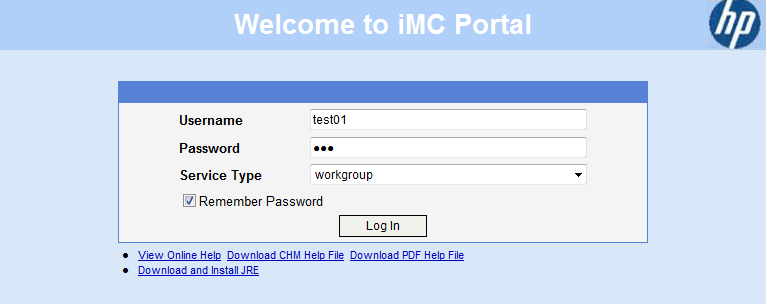
3. Click Log In.
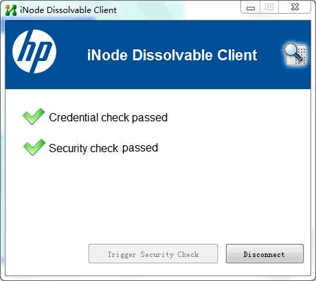
The iNode DC is automatically downloaded to the PC. The iNode DC performs portal authentication and then security check. It notifies you that you have passed credential check and security check, as shown in Figure 18.
Figure 18 Identity check and security check passed
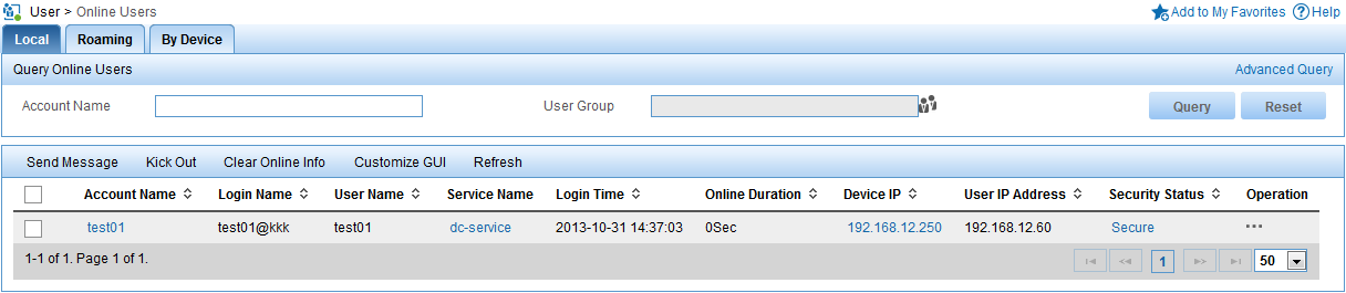
Viewing online users in UAM
1. Click the User tab.
2. From the navigation tree, select Access User > Online Users.
3. Click the Local tab.
4. Verify that user test01 has been added to the online user list, as shown in Figure 19.
Figure 19 User test01 is online