- Released At: 05-07-2024
- Page Views:
- Downloads:
- Table of Contents
- Related Documents
-
|
H3C IMC UAM |
|
LDAP Authentication Configuration Examples |
|
|
Software version: IMC UAM 7.2 (E0402)
|
Copyright © 2016 Hangzhou H3C Technologies Co., Ltd. All rights reserved. No part of this manual may be reproduced or transmitted in any form or by any means without prior written consent of Hangzhou H3C Technologies Co., Ltd. The information in this document is subject to change without notice. |
|
Contents
Example: Using UAM for LDAP authentication
Configuring an access policy for LDAP authentication
Associating an access service with the access policy
Configuring a synchronization policy for the LDAP server
Synchronizing user data from the LDAP server
Triggering 802.1X authentication in the iNode client
Introduction
This document provides examples for using UAM to provide LDAP authentication on a network. UAM forwards authentication requests to the LDAP server and makes access decisions according to the authentication results. LDAP user information is stored both on the LDAP server and UAM.
The examples apply to scenarios where UAM is deployed to work with an existing LDAP server for authentication.
Prerequisites
Make sure the access device supports 802.1X.
Example: Using UAM for LDAP authentication
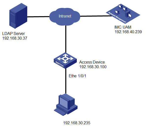
Network configuration
As shown in Figure 1, a user accesses the network by using the account imc001 that is stored on an LDAP server. The LDAP server is a Microsoft Active Directory and uses the default port 389. The domain name is xin.h3c.
Deploy UAM to forward the user's authentication requests to the LDAP server. UAM uses the authentication port 1812, accounting port 1813, and shared key of fine for RADIUS communication.
The switch manages the user in an ISP domain named cert and includes the domain information in the user names to be sent to UAM.
The user accesses the network through the iNode client on a Windows PC.
Software versions used
This configuration example was created and verified on the following platforms:
· IMC UAM 7.2 (E0402)
· H3C S5500-28C-PWR-EI Comware Software, Version 5.20, Release 2220P02
· iNode PC 7.2 (E0402)
Restrictions and guidelines
When you configure LDAP and UAM authentication, follow these restrictions and guidelines:
· Make sure the shared key you configure for the access device on UAM is the same as the CLI configuration on the switch.
· Make sure the authentication port number and the accounting port number you configure for the access device on UAM are the same as the CLI configuration on the switch.
· To select or specify the device IP address, follow these restrictions and guidelines:
¡ If the nas ip command is configured on the switch, use the NAS IP address as the IP address of the access device.
¡ If the nas ip command is not configured on the switch, use the IP address of the interface (including VLAN interface) that connects to UAM as the IP address of the access device.
¡ To select the switch from the resource pool, make sure it is already added to the IMC platform manually or through auto discovery and uses the correct IP address.
¡ If the switch in the resource pool does not use the correct IP address, you must specify the correct IP address of the access device.
· Configure a service suffix for the 802.1X user depending on the authentication domain and username format settings on the switch, as shown in Table 1.
Table 1 Determining the service suffix
|
Username in iNode |
Authentication domain on the switch |
Username format command on the switch |
Service suffix in UAM |
|
imc001@cert |
cert |
user-name-format with-domain |
cert |
|
user-name-format without-domain |
No suffix |
Configuring UAM
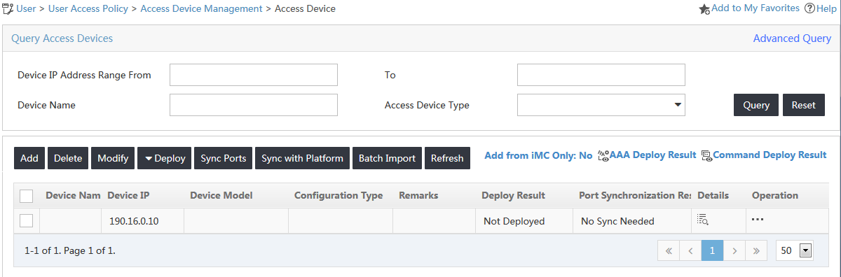
Adding the switch to UAM
1. Click the User tab.
2. From the navigation tree, select User Access Policy > Access Device Management > Access Device.
The access device list opens, as shown in Figure 2.
Figure 2 Accessing the Access Device page
3. On the access device list, click Add.
The Add Access Device page opens, as shown in Figure 3.
Figure 3 Adding an access device
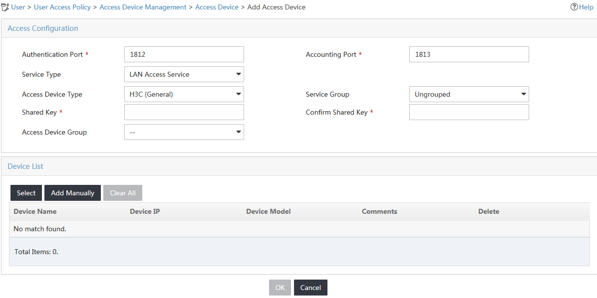
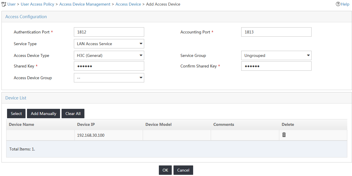
4. Configure the access device parameters, as shown in Figure 4:
a. In the Access Configuration area, enter fine in the Shared Key field and use the default values for the other parameters.
If the Displays Key in parameter is set to Ciphertext (Displays ******) in the system configuration, enter the same shared key in both the Shared Key and Confirm Shared Key fields.
b. Use the default values for other parameters.
Figure 4 Configuring the access parameters
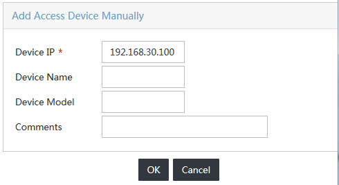
5. Add the switch to UAM as an access device.
You can add a device to UAM either manually or by selecting the device from the IMC platform. This example uses the Add Manually option.
To manually add the switch to UAM:
a. In the Device List area, click Add Manually.
b. On the Add Access Device Manually window, enter 192.168.30.100 in the Device IP field, as shown in Figure 5.
c. Click OK.
Figure 5 Adding an access device manually
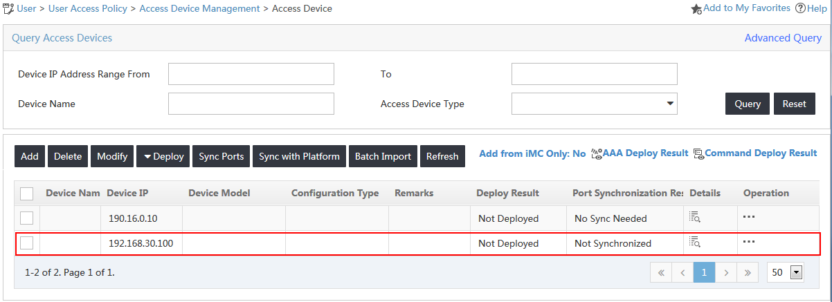
6. On the Add Access Device page, click OK.
The new access device is displayed in the access device list, as shown in Figure 6.
Figure 6 Viewing the new access device
Configuring an access policy for LDAP authentication
1. Click the User tab.
2. From the navigation tree, select User Access Policy > Access Policy.
The access policy list is displayed, as shown in Figure 7.
Figure 7 Accessing the Access Policy page
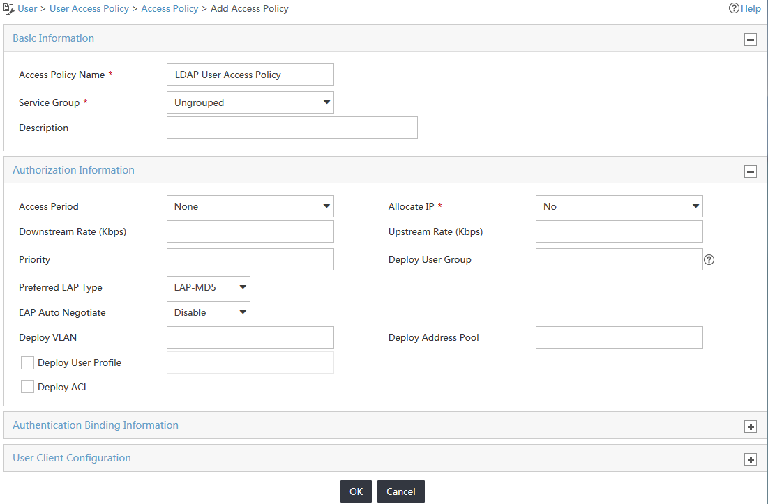
3. Click Add on top of the access policy list.
4. On the Add Access Policy page, configure the following parameters, as shown in Figure 8:
a. Enter LDAP User Access Policy in the Access Policy Name field.
b. Use the default values for other parameters.
Figure 8 Adding an access policy
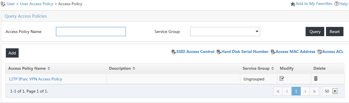
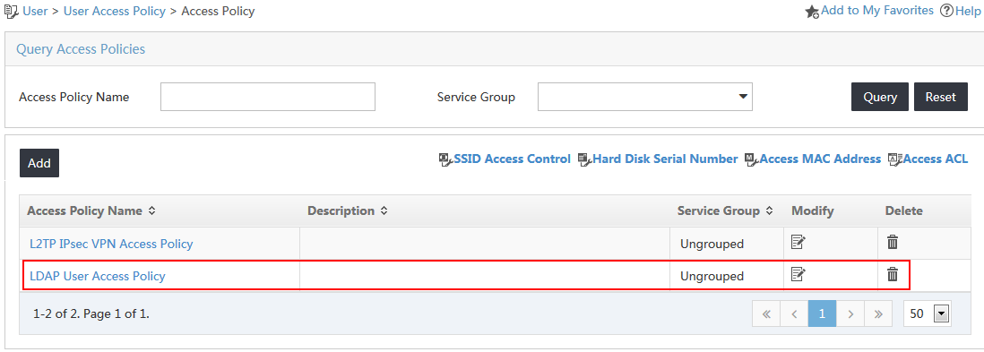
5. Click OK.
The new access policy named LDAP User Access Policy is displayed in the access policy list, as shown in Figure 9.
Figure 9 Viewing the added access policy
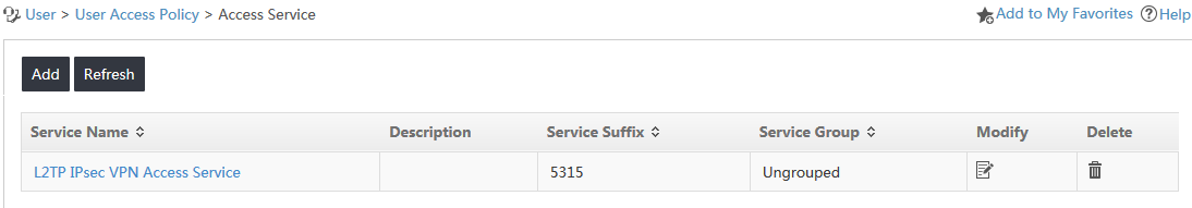
Associating an access service with the access policy
1. Click the User tab.
2. From the navigation tree, select User Access Policy > Access Service.
The Access Service page opens, as shown in Figure 10.
Figure 10 Accessing the Access Service page
3. Click Add on top of the access service list.
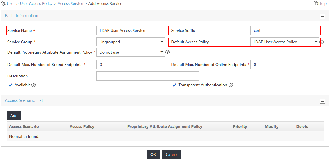
4. On the Add Access Service page, configure the following parameters, as shown in Figure 11:
a. Enter LDAP User Access Service in the Service Name field.
b. Enter cert in the Service Suffix field. For more information about determining the service suffix, see Table 1.
c. Select LDAP User Access Policy from the Default Access Policy list.
d. Use the default values for other parameters.
Figure 11 Adding an access service
5. Click OK.
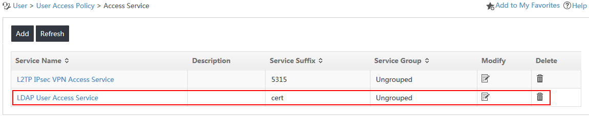
The new access service named LDAP User Access Service is displayed in the access service list, as shown in Figure 12.
Figure 12 Viewing the new access service
Adding an LDAP server
1. Click the User tab.
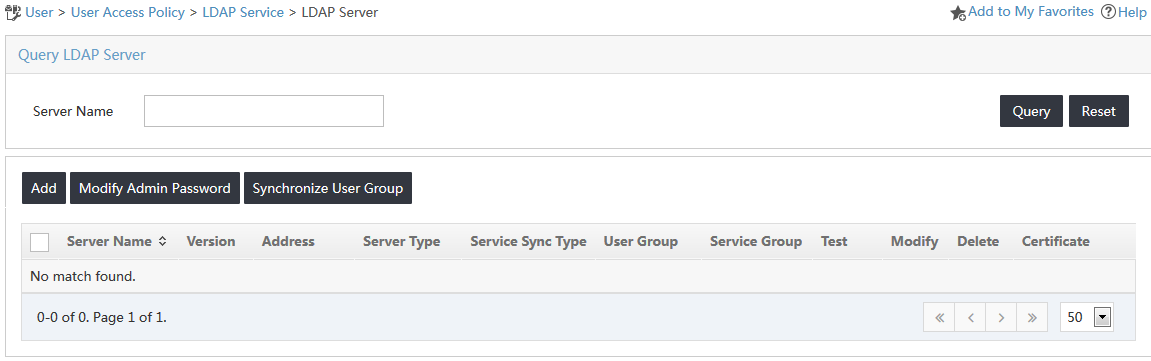
2. From the navigation tree, select User Access Policy > LDAP Service > LDAP Server.
The LDAP Server page opens, as shown in Figure 13.
Figure 13 Accessing the LDAP Server page
3. On the LDAP server list, click Add.
4. On the Add LDAP Server page, configure the following parameters, as shown in Figure 14:
a. Enter a name in the Service Name field to uniquely identify the LDAP server on UAM. This example uses Windows AD as the server name.
b. Enter 192.168.40.200 in the Address field. The combination of the IP address and the base DN must be unique on UAM.
c. Enter the listening port number in the Port field. This example uses the default value 389.
d. Select Microsoft AD from the Server Type list.
e. Enter the absolute path where user data is stored on the LDAP server in the Base DN field. This example uses dc=xin,dc=h3c.
f. Enter the absolute path of the administrator in the Admin DN field. This example uses cn=administrator,cn=users,dc=xin,dc=h3c.
g. Enter the administrator password of the LDAP server in the Admin Password field.
h. Use the default values for other parameters.
|
|
NOTE: When Microsoft AD is selected from the Server Type list, the default value Yes automatically populates the Real-Time AuthN field. The value cannot be changed. |
Figure 14 Adding an LDAP server

5. Click OK.
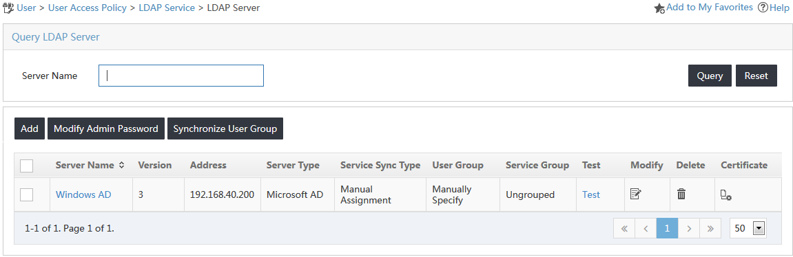
The new LDAP server named Windows AD is displayed in the LDAP server list, as shown in Figure 15.
Figure 15 Viewing the added LDAP server
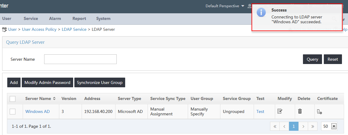
6. Click Test to test the connectivity between IMC and the LDAP server.
The test result opens on the top upper right of the page, as shown in Figure 16.
Figure 16 Viewing the testing result
Configuring a synchronization policy for the LDAP server
1. Click the User tab.
2. From the navigation tree, select User Access Policy > LDAP Service > Sync Policy.
The Sync Policy page opens, as shown in Figure 17.
Figure 17 Accessing the Sync Policy page
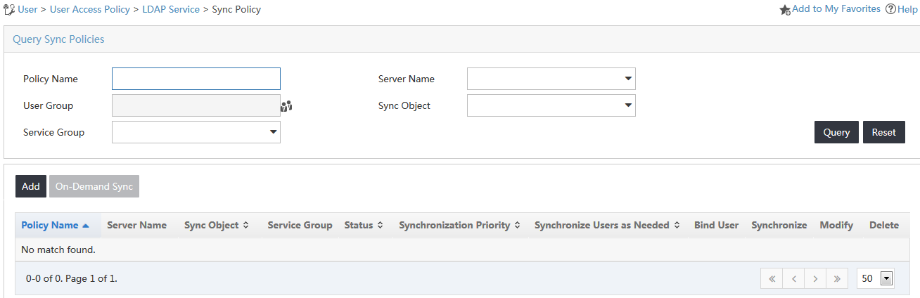
3. Click Add on top of the synchronization policy list.
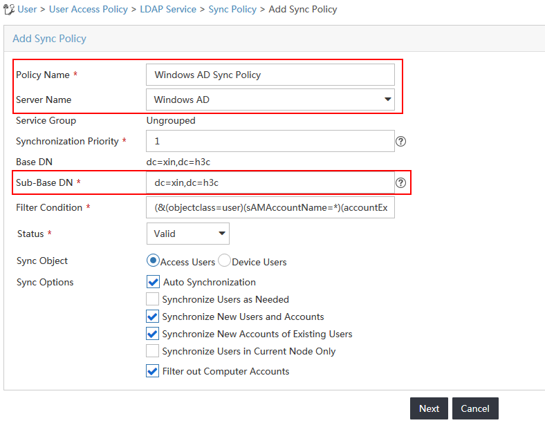
4. On the Add Sync Policy page, configure the following parameters, as shown in Figure 18:
a. Enter Windows AD Sync Policy in the Policy Name field.
b. Select Windows AD from the Server Name list.
c. Enter the absolute subdirectory path where user data is stored on the LDAP server in the Sub-Base DN field. The sub-base DN must be the base DN itself or its subset. This example uses dc=xin,dc=h3c. UAM synchronizes only the user data under the specified subdirectory from the server.
d. Use the default values for other parameters.
Figure 18 Adding a synchronization policy
5. Click Next.
6. On the Add Sync Policy page, configure the following parameters, as shown in Figure 19:
a. In the Access Information area, enter iMC123 in the Password field. By default, the password is not synchronized from the LDAP server.
b. In the Access Service area, select the service named LDAP User Access Service.
c. Use the default values for other parameters.
Figure 19 Configuring policy information

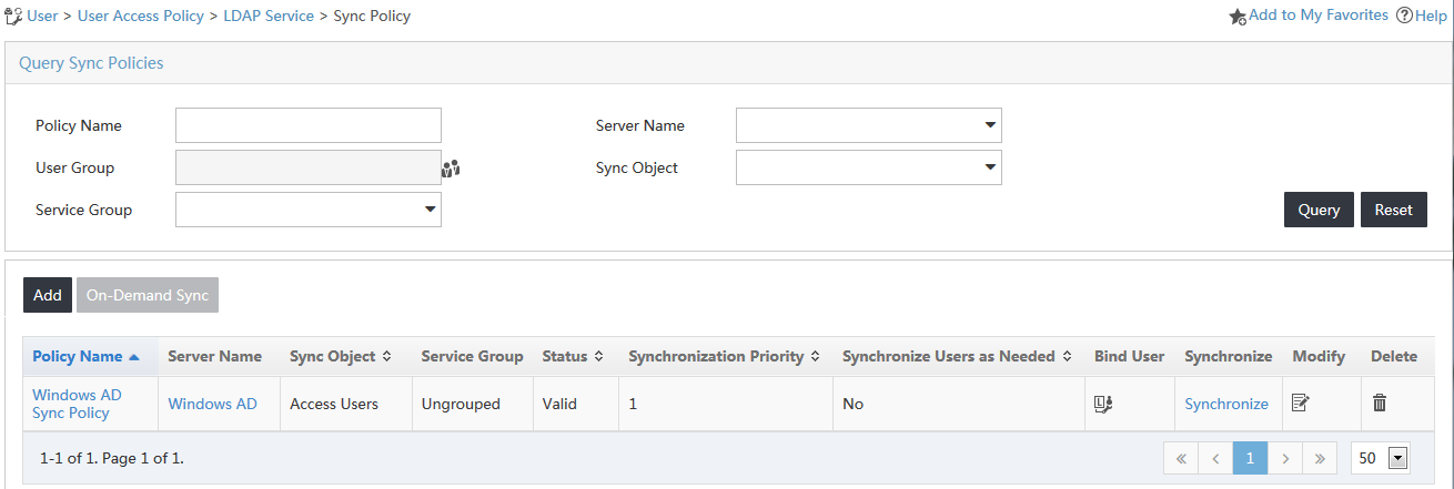
7. Click Finish.
The new synchronization policy named Windows AD Sync Policy is displayed in the synchronization policy list, as shown in Figure 20.
Figure 20 Viewing the new synchronization policy
Synchronizing user data from the LDAP server
1. Click the User tab.
2. From the navigation tree, select User Access Policy > LDAP Service > Sync Policy.
The Sync Policy page opens, as shown in Figure 21.
Figure 21 Accessing the Sync Policy page
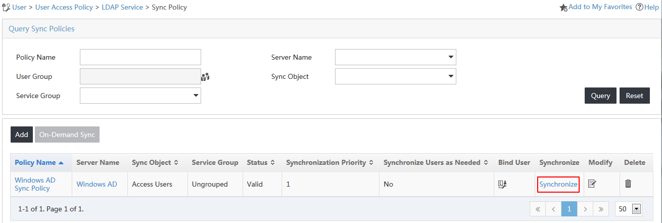
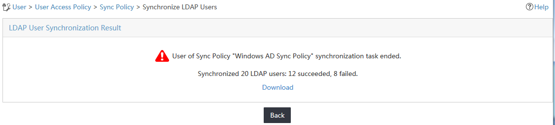
3. Click Synchronize for the policy named Windows AD Sync Policy.
UAM starts to synchronize user data from the LDAP server and displays the synchronization result, as shown in Figure 22.
Figure 22 Viewing the LDAP user synchronization result
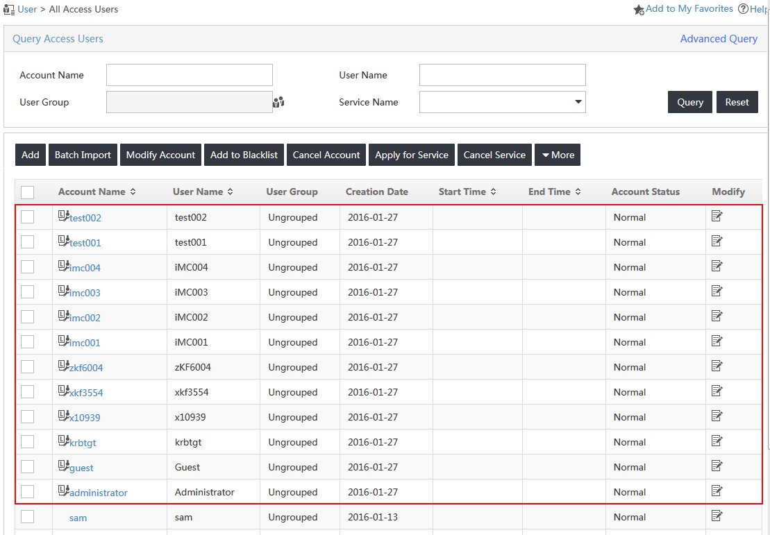
4. From the navigation tree, select Access User > All Access Users.
The synchronized LDAP users appear in the access user list, as shown in Figure 23.
Figure 23 Viewing the synchronized LDAP users
Configuring the switch
1. Configure a RADIUS scheme.
# Create a RADIUS scheme named zzpermit.
<H3C>system-view
System View: return to User View with Ctrl+Z.
[H3C] radius scheme zzpermit
New Radius scheme
# Configure UAM as the primary RADIUS authentication and accounting servers in the scheme. Set the RADIUS authentication port to 1812 and accounting port to 1813.
[H3C-radius-zzpermit] primary authentication 192.168.40.239 1812
[H3C-radius-zzpermit] primary accounting 192.168.40.239 1813
# Configure the shared key to fine to secure RADIUS authentication and accounting communication.
[H3C-radius-zzpermit] key authentication fine
[H3C-radius-zzpermit] key accounting fine
# Configure the switch to include domain information in the user names to be sent to the RADIUS server.
[H3C-radius-zzpermit] user-name-format with-domain
[H3C-radius-zzpermit] quit
2. Configure an ISP domain.
# Add an ISP domain named cert.
[H3C] domain cert
New Domain added.
# Configure the switch to use the RADIUS scheme zzpermit for users in ISP domain cert.
[H3C-isp-cert] authentication lan-access radius-scheme zzpermit
[H3C-isp-cert] authorization lan-access radius-scheme zzpermit
[H3C-isp-cert] accounting lan-access radius-scheme zzpermit
[H3C-isp-cert] quit
3. Configure 802.1X authentication.
# Enable 802.1X globally and on Ethernet 1/0/1. The 802.1X function takes effect on the interface only when 802.1X is enabled globally and on the interface.
[H3C] dot1x
802.1X is enabled globally.
[H3C] dot1x interface Ethernet 1/0/1
802.1X is enabled on port Ethernet 1/0/1.
# Set the 802.1X authentication method. With LDAP authentication, you can set the 802.1X authentication method to EAP or PAP. In this example, the 802.1X authentication method is set to PAP.
[H3C] dot1x authentication-method pap
PAP authentication is enabled.
Verifying the configuration
Make sure the version of the iNode client installed on the PC is compatible with IMC UAM. For more information about the compatibility, see the UAM readme file.
Triggering 802.1X authentication in the iNode client
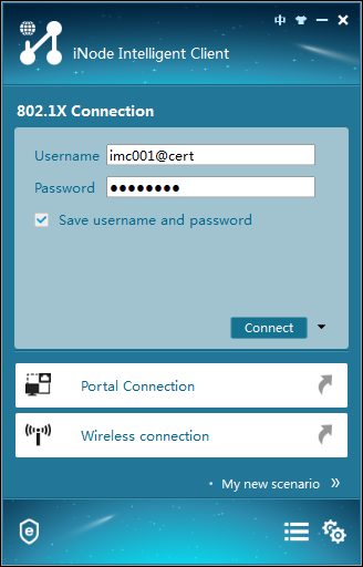
1. On the iNode client, click 802.1X Connection.
The 802.1X Connection window opens.
2. Enter the username and password, and click Connect, as shown in Figure 24.
Figure 24 Viewing the 802.1X connection
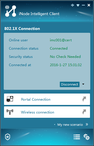
The authentication process starts. The authentication result shows that the connection has been established, as shown in Figure 25.
Figure 25 Authentication information
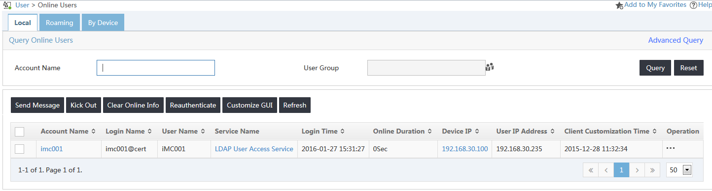
Viewing online users in UAM
1. Click the User tab.
2. From the navigation tree, select Access User > Online Users.
3. Click the Local tab.
4. Verify that the user named imc001 has been added to the online user list, as shown in Figure 26.
Figure 26 Viewing the online user