- Released At: 05-07-2024
- Page Views:
- Downloads:
- Related Documents
-
|
H3C IMC UAM |
|
L2TP over IPsec Authentication with UAM Configuration Examples |
|
|
Software version: IMC UAM 7.2 (E0403)
|
Copyright © 2016 Hangzhou H3C Technologies Co., Ltd. All rights reserved. No part of this manual may be reproduced or transmitted in any form or by any means without prior written consent of Hangzhou H3C Technologies Co., Ltd. The information in this document is subject to change without notice. |
|
Contents
Example: Configuring L2TP over IPsec authentication with UAM
Configuring IMC UAM as the RADIUS server
Introduction
This document provides examples for using UAM as the RADIUS server to authenticate L2TP over IPsec VPN connections.
Prerequisites
The access device must support routing and PPP, and the iNode PC client must support L2TP/IPsec VPN authentication.
Example: Configuring L2TP over IPsec authentication with UAM
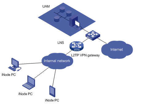
Network configuration
As shown in Figure 1, configure UAM as the RADIUS server to authenticate L2TP users and assign access control policies to the L2TP VPN gateway.
Configure the L2TP VPN gateway to control internal network access and Internet access according to the access control policies assigned by UAM.
Procedures
Configuring the LNS
This example uses H3C SecPath F5040 as the LNS.
1. Enter system view.
<H3C> system-view
System View: return to User View with Ctrl+Z.
2. Configure the DHCP relay agent.
# Enable DHCP and specify DHCP server 192.168.1.32 for DHCP server group 0.
[H3C] dhcp enable
[H3C] dhcp relay server-group 0 ip 192.168.1.32
3. Configure the RADIUS server.
# Configure a RADIUS scheme named wkf5315.
[H3C] radius scheme wkf5315
New Radius scheme
# Specify IMC UAM as the authentication and accounting server.
[H3C-radius-wkf5315] primary authentication 192.168.1.17 1812
[H3C-radius-wkf5315] primary accounting 192.168.1.17 1813
# Configure shared keys for authentication and accounting.
[H3C-radius-wkf5315] key authentication simple expert
[H3C-radius-wkf5315] key accounting simple expert
# Include the domain names in usernames sent to the RADIUS server.
[H3C-radius-wkf5315] user-name-format with-domain
# Configure the service type as extended to better support UAM and EAD.
[H3C-radius-wkf5315] server-type extended
[H3C-radius-wkf5315] quit
4. Configure an ISP domain.
# Configure the domain name to be the same as the service suffix in UAM.
[H3C] domain 5315
# Use RADIUS scheme wkf5315 to authenticate PPP users.
[H3C-isp-5315] authentication ppp radius-scheme wkf5315
[H3C-isp-5315] authorization ppp radius-scheme wkf5315
[H3C-isp-5315] accounting ppp radius-scheme wkf5315
# Create an IP address pool.
[H3C] ip pool 1 200.1.1.2 200.1.1.100
5. Configure a VT interface.
# Create a VT interface, and configure CHAP authentication for PPP users by using domain 5315.
[H3C] interface Virtual-Template 1
[H3C-Virtual-Template1] ppp authentication-mode chap domain 5315
# Configure the local IP address, which must be within the same network as the L2TP peer but cannot belong to the address pool of the peer.
[H3C-Virtual-Template1] ip address 200.1.1.1 255.255.255.0
# Specify an IP address pool for PPP users.
[H3C-Virtual-Template1] remote address pool 1
6. Configure L2TP.
# Enable L2TP, and create an L2TP group.
[H3C] l2tp enable
[H3C] l2tp-group 1 mode lns
# Specify a VT interface for receiving calls from L2TP users, and configure the tunnel name as iNode.
[H3C-l2tp1] allow l2tp virtual-template 1 remote iNode
# Configure an authentication key for the L2TP tunnel.
[H3C-l2tp1] tunnel password simple 123456
[H3C-l2tp1] quit
7. Configure an IPsec proposal.
# Create an IPsec transform set named tran1.
[H3C] ipsec transform-set tran1
# Specify the encapsulation mode as tunnel.
[H3C-ipsec-transform-set-tran1] encapsulation-mode tunnel
# Specify the security protocol as AH for the IPsec proposal.
[H3C-ipsec-transform-set-tran1] protocol ah
# Specify the authentication algorithm for AH to MD5.
[H3C-ipsec-transform-set-tran1] ah authentication-algorithm md5
[H3C-ipsec-transform-set-tran1] quit
8. Configure an IKE proposal.
# Create an IKE proposal. For successful tunnel establishment, at least one proposal on both sides must match.
[H3C] ike proposal 1
# Specify pre-share as the authentication method for the IKE proposal.
[H3C-ike-proposal-1] authentication-method pre-share
# Set the authentication algorithm to MD5.
[H3C-ike-proposal-1] authentication-algorithm md5
# Set the encryption algorithm to DES-CBC.
[H3C-ike-proposal-1] encryption-algorithm des-cbc
# Specify a DH group for key negotiation in phase 1.
[H3C-ike-proposal-1] dh group1
# Set the IPsec SA lifetime to 86400 seconds.
[H3C-ike-proposal-1] sa duration 86400
[H3C-ike-proposal-1] quit
9. Configure an IKE keychain.
# Create an IKE keychain named keychain1.
[H3C] ike keychain keychain1
# Specify a plain text of 123 as the pre-shared key to be used with the remote peer at 190.19.19.0/24.
[H3C-ike-keychain-keychain1] pre-shared-key address 190.19.19.0 24 key simple 123
[H3C-ike-keychain-keychain1] quit
10. Configure an IKE profile.
# Create an IKE profile named wang.
[H3C] ike profile wang
# Specify that IKE negotiation operates in main mode.
[H3C-ike-profile-wang] exchange-mode main
# Configure the local ID as IP address 190.19.19.1.
[H3C-ike-profile-wang] local-identity address 190.19.19.1
# Configure a peer ID with the identity type as IP address in the range of 190.19.19.2 to 190.19.19.254.
[H3C-ike-profile-wang] match remote identity address 190.19.19.2 190.19.19.254
# Specify an IKE keychain named keychain1.
[H3C-ike-profile-wang] keychain keychain1
# Specify an IKE proposal named 1.
[H3C-ike-profile-wang] proposal 1
[H3C-ike-profile-wang] quit
11. Configure an ACL.
# Create ACL 3000.
[H3C] acl number 3000
# Define an ACL rule to identify the IP traffic to be protected by IPsec.
[H3C-acl-adv-3000] rule 0 permit ip
[H3C-acl-adv-3000] quit
12. Configure an IPsec policy template.
# Create an IPsec policy template named 1.
[H3C] ipsec policy-template tempolicy 1
# Specify the IPsec transform set, IKE profile, and ACL for the IPsec policy template.
[H3C-ipsec-policy-template tempolicy-1] transform-set tran1
[H3C-ipsec-policy-template tempolicy-1] ike-profile wang
[H3C-ipsec-policy-template tempolicy-1] security acl 3000
[H3C-ipsec-policy-template tempolicy-1] quit
13. Create an IKE-based IPsec policy entry named vpnpolicy and sequence number 1 by using IPsec policy template tempolicy.
[H3C] ipsec policy vpnpolicy 1 isakmp template tempolicy
14. Enable IPsec on the LNS interface that connects to the user network.
# Enter the view of Ethernet 3/1 that connects to the user network.
[H3C] interface Ethernet 3/1
# Configure the interface to operate in Layer 3 mode, and enable the DHCP relay agent on it.
[H3C-Ethernet3/1] port link-mode route
[H3C-Ethernet3/1] ip address 190.19.19.1 255.255.255.0
[H3C-Ethernet3/1] dhcp select relay
[H3C-Ethernet3/1] dhcp relay server-select 0
# Enable the IPsec policy.
[H3C-Ethernet3/1] ipsec apply policy vpnpolicy
If the PCs run Windows Vista or later, configure the IPsec proposal and IKE profile as follows:
1. Configure an IKE profile.
# Create an IKE profile named wang.
[H3C] ike profile wang
# Specify the IKE negotiation mode as aggressive.
[H3C-ike-profile-wang] exchange-mode aggressive
# Configure the local ID with the identity type of FQDN name and the value of LNS.
[H3C-ike-profile-wang] local-identity fqdn LNS
# Configure a peer ID with the identity type of FQDN name and the value of LAC.
[H3C-ike-profile-wang] match remote identity fqdn LAC
# Specify an IKE keychain named keychain1.
[H3C-ike-profile-wang] keychain keychain1
# Specify an IKE proposal named 1.
[H3C-ike-profile-wang] proposal 1
[H3C-ike-profile-wang] quit
2. Configure an IPsec proposal.
# Create an IPsec transform set named tran1.
[H3C] ipsec transform-set tran1
# Specify the encapsulation mode as tunnel.
[H3C-ipsec-transform-set-tran1] encapsulation-mode tunnel
# Specify the security protocol as ESP for the IPsec proposal.
[H3C-ipsec-transform-set-tran1] protocol esp
# Specify the authentication algorithm for ESP to MD5.
[H3C-ipsec-transform-set-tran1] esp authentication-algorithm md5
# Specify the encryption algorithm for ESP to DES-CBC.
[H3C-ipsec-transform-set-tran1] esp encryption-algorithm des-cbc
[H3C-ipsec-transform-set-tran1] quit
Configuring IMC UAM as the RADIUS server
Adding the LNS as an access device
1. Click the User tab.
2. From the navigation tree, select User Access Policy > Access Device Management > Access Device, as shown in Figure 2.
Figure 2 Accessing the access device list page

3. Click Add.
The Add Access Device page opens, as shown in Figure 3.
Figure 3 Adding an access device

4. Manually add the LNS.
You can add an access device by clicking the Select button or the Add Manually button in the Device List area. Follow these guidelines to configure an IP address for an access device:
¡ If you configure a RADIUS scheme with the nas ip command being executed on the device, the IP address of the access device in UAM must be the same as that configured by the nas ip command.
¡ If you configure a RADIUS scheme without the nas ip command being executed on the device, the IP address of the access device in UAM must be the IP address of the device's interface that connects to UAM.
The IP address cannot be modified if the device is selected from the IMC platform. It can be modified if the device is added manually.
To manually add the LNS:
a. Click Add Manually in the Device List area.
The page for adding an access device manually opens, as shown in Figure 4.
Figure 4 Configuring the IP address for the access device

b. Enter the IP address of the access device.
c. Click OK to return to the page for adding an access device.
5. In the Access Configuration area, configure the following common parameters, as shown in Figure 5:
¡ Authentication Port—Enter the authentication port. The value must be the same as that configured on the LNS at the CLI. The default port for UAM and the LNS is 1812.
¡ Accounting Port—Enter the accounting port. The value must be the same as that configured on the LNS at the CLI. The default port for UAM and the LNS is 1813.
|
|
NOTE: The device supports only UAM that acts as both the authentication server and accounting server. |
¡ Service Type—Select LAN Access Service or Device Management Service from the list. LAN access service is used for network access and device management service is used for the administrator to log in to and manage devices.
¡ Access Device Type—Select an access device type from the list. The type can be standard, predefined in UAM, or administrator-defined. You can select STANDARD(Standard) for devices that support standard RADIUS protocols. Predefined access device types include H3C(General), 3COM(General), HUAWEI(General), CISCO(General), RG(General), HP(MSM), HP(Comware), MICROSOFT(General), JUNIPER(General), and HP(ProCurve).
¡ Service Group—Select a service group to which the LNS belongs. You can organize access devices into different service groups for distributed management.
¡ Shared Key/Confirm Shared Key—Enter the shared key twice for UAM to authenticate the LNS. The value must be the same as that configured on the LNS at the CLI.
¡ Access Device Group—Select the access device group to which you want to add the LNS. If you do not want to add the LNS to any access device group, select two hyphens (--) from the list.
Figure 5 Configuring common parameters

6. Click OK.
On the page that opens, click the Back to Access Device List link to view the added access device in the Access Device List, as shown in Figure 6.
Figure 6 Viewing the added access device

Adding an access policy
1. Click the User tab.
2. From the navigation tree, select User Access Policy > Access Device Management, as shown in Figure 7.
Figure 7 Accessing the access policy list page

3. Click Add.
The page for adding an access policy opens, as shown in Figure 8.
Figure 8 Adding an access policy

4. Enter the access policy name.
5. Click OK.
On the page that opens, view the added access policy, as shown in Figure 9.
Figure 9 Viewing the added access policy

Adding an access service
An access service is a group of policies for user authentication and authorization.
1. Click the User tab.
2. From the navigation tree, select User Access Policy > Access Service, as shown in Figure 10.
Figure 10 The access service list page

3. Click Add.
The Add Access Service page opens, as shown in Figure 11.
Figure 11 Adding an access service

4. Configure basic information:
¡ Service Name—Enter the unique name of the service.
¡ Service Suffix—Enter the service suffix 5315. UAM uses the service suffix to identify the name of the domain to be used for endpoint authentication. The username and service suffix entered by the endpoint user are related to the authentication domain. The service suffix configuration varies, as shown in Table 1.
¡ Service Group—Select a service group or Ungrouped from the list. You can add services to different service groups to facilitate management.
¡ Default Access Policy—Select the previously added access policy.
¡ Other parameters—Use the default values.
Table 1 Service suffix and other configurations
|
Authentication username |
Authentication domain on the access device |
Commands configured on the access device |
Service suffix in UAM |
|
X@Y |
Y |
user-name-format with-domain |
Y |
|
user-name-format without-domain |
None |
||
|
X |
[Default Domain] (Default domain on the access device) |
user-name-format with-domain |
[Default Domain] |
|
user-name-format without-domain |
None |
5. Click OK.
On the page that opens, view the added access service, as shown in Figure 12.
Figure 12 Viewing the added access service

Adding an access user
1. Click the User tab.
2. Select Access User > All Access Users from the navigation tree, as shown in Figure 13.
Figure 13 Accessing the access user list page

3. Click Add.
The Add Access User page opens, as shown in Figure 14.
Figure 14 Adding an access user

4. Configure the name of the platform user to which the access user is attached.
You can use one of the following methods:
¡ Click Select. In the window that opens, click Query, and select an existing platform user, as shown in Figure 15. Click OK.
Figure 15 Selecting an existing platform user

¡ Click Add User to add a new platform user, and configure the username, identity number, and other parameters, as shown in Figure 16. Click OK.
Figure 16 Adding a new platform user

5. Enter the unique account name of the access user.
6. Enter the same password in the Password and Confirm Password fields.
7. Select the previously added access service in the Access Service list.
8. Use the default values for other parameters.
Figure 17 shows the page after configurations.
Figure 17 Viewing the access account settings

9. Click OK.
On the page that opens, view the added access user, as shown in Figure 18.
Figure 18 Viewing the added access user

Verifying the configuration
1. Install the iNode client with the L2TP/IPsec VPN feature enabled.
The version of the iNode client must be compatible with IMC UAM. For more information about compatibility, see the UAM readme file.
2. Configure the properties of the L2TP IPsec VPN connection.
a. Open the iNode client, and click the L2TP IPsec VPN connection area to expand this area, as shown in Figure 19.

b. Access the Properties windows of the L2TP IPsec VPN connection by using one of the following methods:
- Click the icon ![]() in the connection
area, and select Properties from the menu, as shown in Figure 20.
in the connection
area, and select Properties from the menu, as shown in Figure 20.
Figure 20 Accessing the connection Properties window

- Click the Manage icon ![]() in the iNode main window, right-click the L2TP IPsec VPN connection
icon in the Management Plat
window, and select Properties from the menu, as
shown in Figure 21.
in the iNode main window, right-click the L2TP IPsec VPN connection
icon in the Management Plat
window, and select Properties from the menu, as
shown in Figure 21.
Figure 21 Accessing the connection Properties window

3. Configure basic settings for the L2TP IPsec VPN connection, as shown in Figure 22.
Make sure the basic settings are configured in the same way as those configured for the IKE peer on the LNS.
Figure 22 Configuring VPN connection basic settings

4. Click Advanced, and configure advanced properties for the connection according to the specified negotiation mode, as shown in Figure 23, Figure 24, Figure 25, Figure 26, and Figure 27.
Make sure the advanced settings are configured in the same way as those configured on the LNS.
¡ In main negotiation mode
Figure 23 Configuring the L2TP settings

Figure 24 Configuring the IPsec settings

Figure 25 Configuring the IKE settings

¡ In aggressive negotiation mode
Figure 26 Configuring the IPsec settings

Figure 27 Configuring the IKE settings

5. Perform L2TP/IPsec VPN authentication.
a. Click the L2TP IPsec VPN connection area.
b. Enter the username and password, and click Connect, as shown in Figure 28.
Figure 28 Entering the username and password

The authentication starts. The authentication information shows that the connection has been established, as shown in Figure 29.
Figure 29 Verifying the authentication success

