- Released At: 05-07-2024
- Page Views:
- Downloads:
- Table of Contents
- Related Documents
-
|
H3C IMC UAM |
|
Gateway Spoofing Attack Prevention Configuration Examples |
|
|
Software version: IMC UAM 7.2 (E0405)
|
Copyright © 2016 Hangzhou H3C Technologies Co., Ltd. All rights reserved. No part of this manual may be reproduced or transmitted in any form or by any means without prior written consent of Hangzhou H3C Technologies Co., Ltd. The information in this document is subject to change without notice. |
|
Contents
Example: Configuring gateway spoofing attack prevention
Configuring the switch as an access device
Triggering 802.1X authentication
Viewing the gateway configuration of the PC
Re-authenticating the access user without binding the gateway
Introduction
The examples apply to enterprise and campus networks, which are vulnerable to gateway spoofing attacks by ARP attackers.
Prerequisites
Make sure the access device supports 802.1X.
Example: Configuring gateway spoofing attack prevention
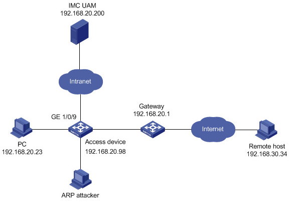
Network configuration
As shown in Figure 1, UAM is deployed on the server at 192.168.20.200. A Windows PC user attempts to access the network by using an 802.1X connection in the iNode client. The user accesses the network by using an account named test.
The access device manages 802.1X users in an ISP domain named arp and includes the domain name in the usernames that it sends for authentication.
Set the shared keys for secure RADIUS communication to uam123, set the authentication port to 1812, and set the accounting port to 1813.
Configure UAM to deploy the gateway configuration to the PC to prevent gateway spoofing attacks.
Software versions used
This configuration example was created and verified on the following platforms:
· IMC UAM 7.2 (E0405)
· H3C S3600-28TP-EI Comware Software, Version 5.20, Release 2103
· iNode PC 7.2 (E0402)
Restrictions and guidelines
When you configure UAM to deploy the gateway configuration, follow these restrictions and guidelines:
· UAM must provide both authentication and accounting services. Do not use a second server (other than the UAM server) to provide accounting.
· Make sure the port and shared key settings you configure for the access device in UAM are the same as the ones in the CLI configuration on the switch.
· To select the switch from the resource pool, make sure it is already added to the IMC platform, either manually or through auto discovery.
· Configure a service suffix for the 802.1X user depending on the authentication domain and username format settings on the switch, as shown in Table 1.
Table 1 Determining the service suffix
|
Username in iNode |
Authentication domain on the switch |
Username format command on the switch |
Service suffix in UAM |
|
|
test@arp |
arp |
user-name-format with-domain |
arp |
|
|
user-name-format without-domain |
No suffix |
|||
Configuring UAM
Configuring the switch as an access device
1. Click the User tab.
2. From the navigation tree, select User Access Policy > Access Device Management > Access Device.
The Access Device page opens, as shown in Figure 2.
Figure 2 Accessing the Access Device page
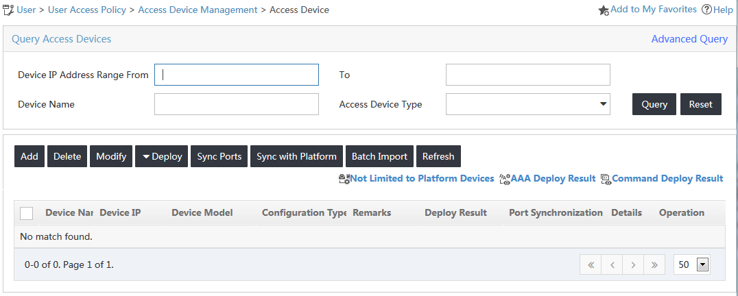
3. In the access device list, click Add.
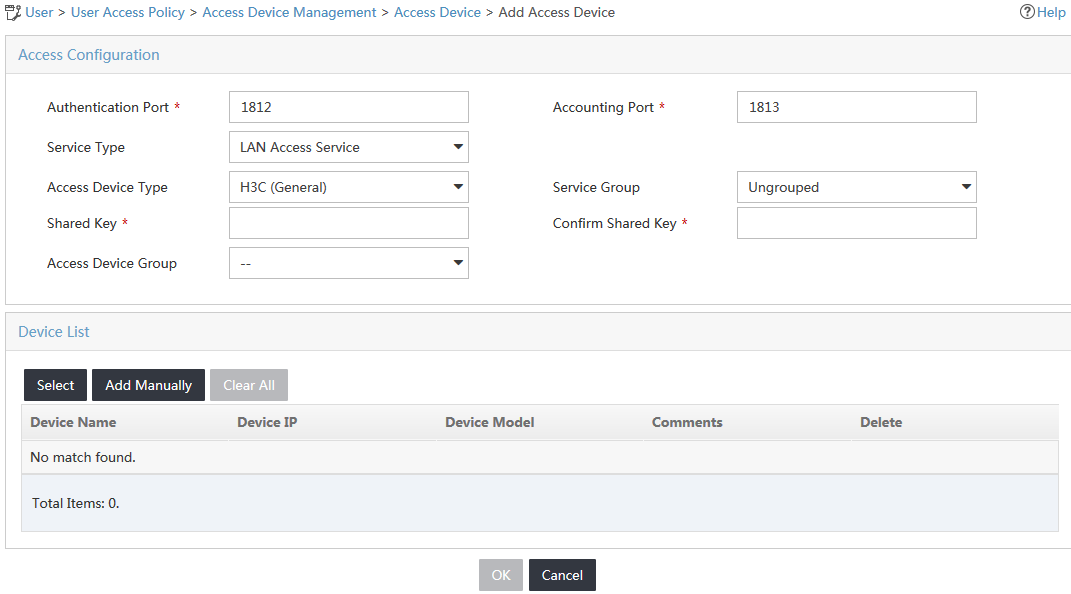
The Add Access Device page opens, as shown in Figure 3.
Figure 3 Accessing the Add Access Device page
4. Add the switch to UAM as an access device.
You can add a device to UAM either manually or by selecting the device from the IMC platform. This example uses the Add Manually option.
To manually add the switch to UAM:
a. In the Device List area, click Add Manually.
b. On the Add Access Device Manually window, enter 192.168.20.98 in the Start IP field, as shown in Figure 4.
Figure 4 Adding an access device manually
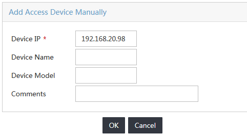
c. Click OK.
5. Configure common parameters for the access device, as shown in Figure 5:
a. In the Access Configuration area, enter uam123 in the Shared Key and Confirm Shared Key fields.
b. Use the default values for other parameters.
Figure 5 Adding an access device
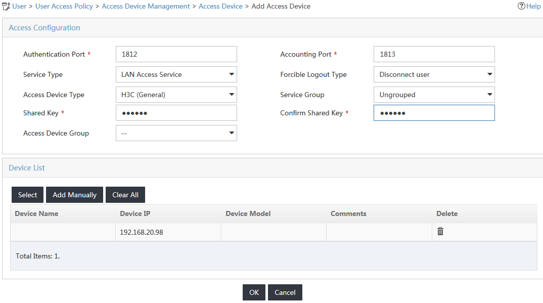
6. Click OK.
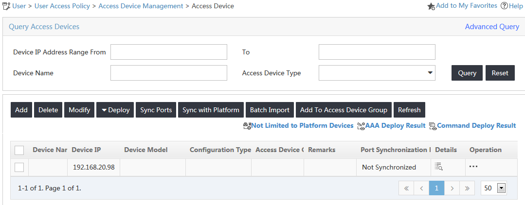
7. On the results page that opens, click Back to Access Device List.
The new access device opens in the access device list, as shown in Figure 6.
Figure 6 Viewing the new access device
Configuring the user gateway
2. From the navigation tree, select User Access Policy > Access Device Management > Access Device.
The Access Device page opens.
3. In the access device list, click the Operation icon ![]() for the access device that you want to use
to deploy the gateway configuration, and select User Gateway from the shortcut menu.
for the access device that you want to use
to deploy the gateway configuration, and select User Gateway from the shortcut menu.
The User Gateway page opens.
4. Click Add.
The Add User Gateway page opens.
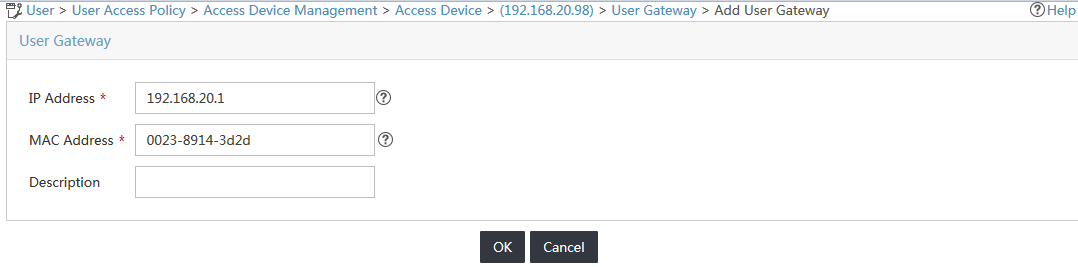
5. Configure user gateway parameters, as shown in Figure 7:
a. Enter 192.168.20.1 in the IP Address field.
b. Enter 00-23-89-14-3d-2d in the MAC Address field.
c. Configure the Description field as needed.
Figure 7 Adding a user gateway
d. Click OK.
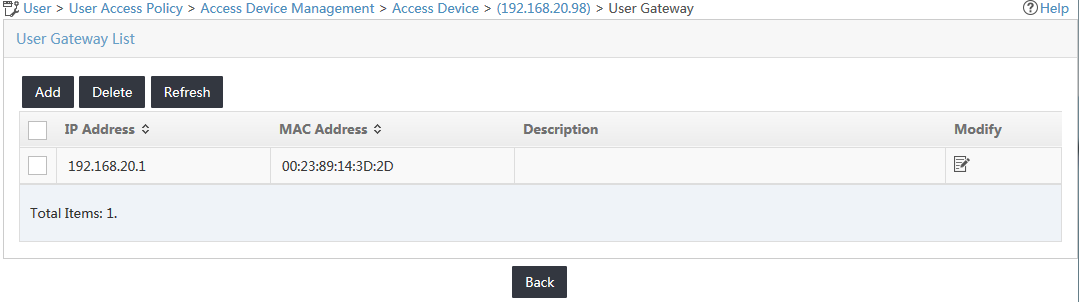
The new user gateway is displayed in the user gateway list, as shown in Figure 8.
Figure 8 Viewing the new user gateway
Configuring an access policy
1. Click the User tab.
2. From the navigation tree, select User Access Policy > Access Policy.
3. In the access policy list, click Add.
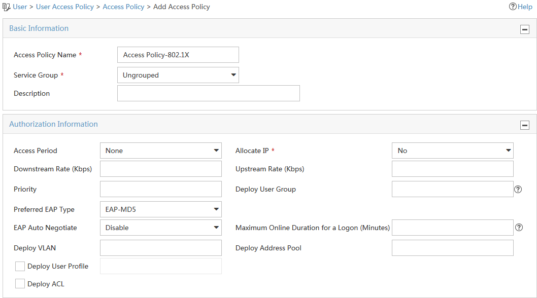
The Add Access Policy page opens, as shown in Figure 9.
4. In the Basic Information area, enter Access Policy-802.1X in the Access Policy Name field.
5. Use the default values for other parameters.
Figure 9 Adding an access policy
6. Click OK.
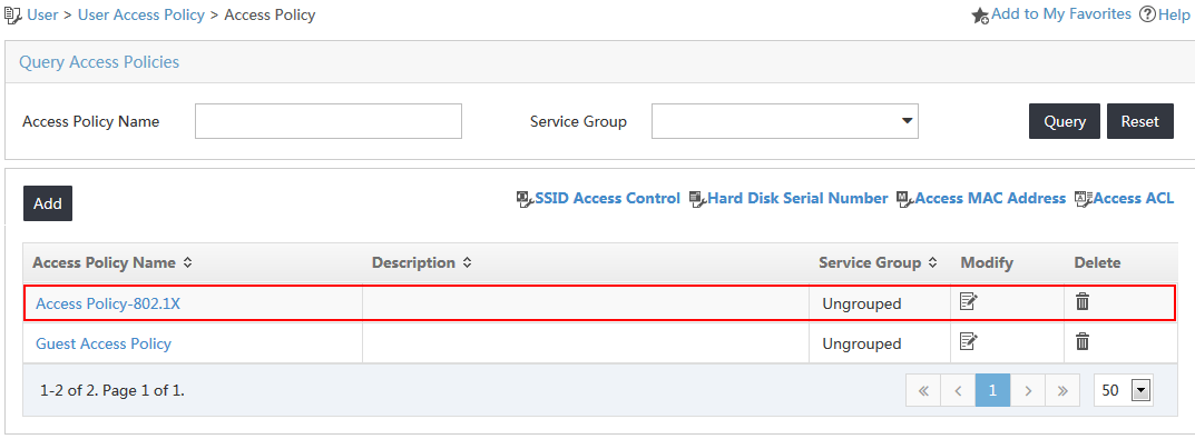
The new access policy is displayed in the access policy list, as shown in Figure 10.
Figure 10 Viewing the new access policy
Configuring an access service
1. Click the User tab.
2. From the navigation tree, select User Access Policy > Access Service.
3. On the Access Service list, click Add.
The Add Access Service page opens.
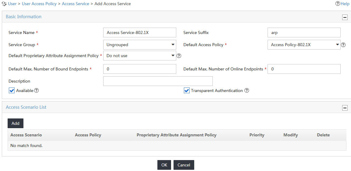
4. Configure basic information for the access service, as shown in Figure 11:
a. Enter Access Service-802.1X in the Service Name field.
b. Enter arp in the Service Suffix field. For more information about determining the service suffix, see Table 1.
c. Select Access Policy-802.1X from the Default Access Policy list.
d. Use the default values for other parameters.
Figure 11 Adding an access service
5. Click OK.
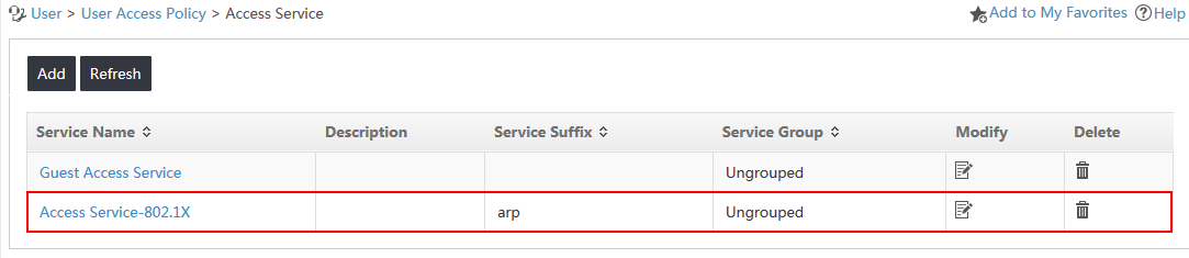
The new access service is displayed in the access service list, as shown in Figure 12.
Figure 12 Viewing the new access service
Configuring an access user
1. Click the User tab.
2. From the navigation tree, select Access User > All Access Users.
3. In the access user list, click Add.
The Add Access User page opens.
4. Configure basic parameters for the access user, as shown in Figure 13.
a. In the User Name field, click Select to select an existing user account from the IMC platform, or click Add User to add a new IMC platform user.
This example uses the Add User option.
In the Add User window, enter test in the User Name field and 1497 in the Identity Number field, and click OK.
b. Enter test in the Account Name field.
c. Enter 1234 in the Password and Confirm Password fields.
d. In the Access Service area, select the service named Access Service-802.1X.
e. Use the default values for other parameters.
Figure 13 Adding an access user

5. Click OK.
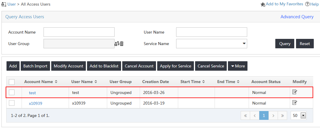
The new access user is displayed in the access user list, as shown in Figure 14.
Figure 14 Viewing the new access user
Configuring the switch
1. Configure a RADIUS scheme:
# Create a RADIUS scheme named arpPolicy.
<AccDevice> system-view
System View: return to User View with Ctrl+Z.
[AccDevice] radius scheme arpPolicy
New Radius scheme
# Configure UAM as the primary RADIUS authentication and accounting server. Set the RADIUS authentication port to 1812, and set the accounting port to 1813.
[AccDevice-radius-arpPolicy] primary authentication 192.168.20.200 1812
[AccDevice-radius-arpPolicy] primary accounting 192.168.20.200 1813
# Configure the shared key to uam123 to secure RADIUS authentication and accounting communication.
[AccDevice-radius-arpPolicy] key authentication uam123
[AccDevice-radius-arpPolicy] key accounting uam123
# Specify the RADIUS server type as extended to support UAM.
[AccDevice-radius-arpPolicy] server-type extended
# Configure the switch to include domain information in the usernames to be sent to the RADIUS server.
[AccDevice-radius-arpPolicy] user-name-format with-domain
[AccDevice-radius-arpPolicy] quit
2. Configure an ISP domain:
# Create an ISP domain named arp.
[AccDevice] domain arp
# Configure the switch to use the RADIUS scheme arpPolicy for LAN users.
[AccDevice-isp-arp] authentication lan-access radius-scheme arpPolicy
[AccDevice-isp-arp] authorization lan-access radius-scheme arpPolicy
[AccDevice-isp-arp] accounting lan-access radius-scheme arpPolicy
[AccDevice-isp-arp] quit
3. Configure 802.1X authentication:
# Configure the switch to perform EAP termination and to support all CHAP authentication methods for RADIUS communication.
[AccDevice] dot1x authentication-method eap
EAP authentication enabled already.
# Enable 802.1X globally and on Ethernet 1/0/9. The 802.1X function takes effect on the interface only when 802.1X is enabled globally and on the interface.
[AccDevice] dot1x
802.1X is enabled globally.
[AccDevice] dot1x interface Ethernet 1/0/9
802.1X is enabled on port Ethernet 1/0/9.
Verifying the configuration
Triggering 802.1X authentication
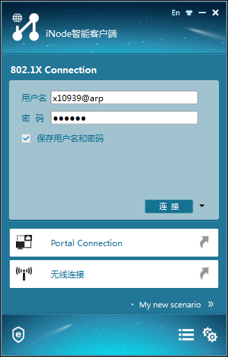
1. On the iNode client, double-click 802.1X Connection.
The 802.1X Connection window opens.
2. Enter the username and password, and then click Connect, as shown in Figure 15.
Figure 15 Triggering 802.1X authentication
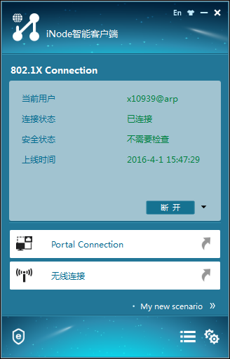
3. Verify that the connection can be successfully established, as shown in Figure 16.
Figure 16 Viewing the authentication result
Viewing the gateway configuration of the PC
After the user passes authentication, the access device automatically deploys the gateway configuration to the PC.
1. From the PC, ping the remote host.
The PC and the remote host can ping each other, as shown in Figure 17.
Figure 17 Viewing the gateway binding information
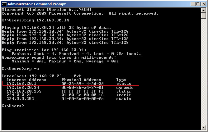
2. Display the gateway configuration of the PC.
The gateway type of the PC is static.
3. Simulate a gateway spoofing attack, and then display the gateway configuration of the PC.
The gateway configuration for the PC is unchanged.
4. Ping the remote host again.
The PC and the remote host can still ping each other.
Re-authenticating the access user without binding the gateway
1. Remove the user gateway configuration for the access device on UAM.
2. Trigger 802.1X authentication in the iNode client.
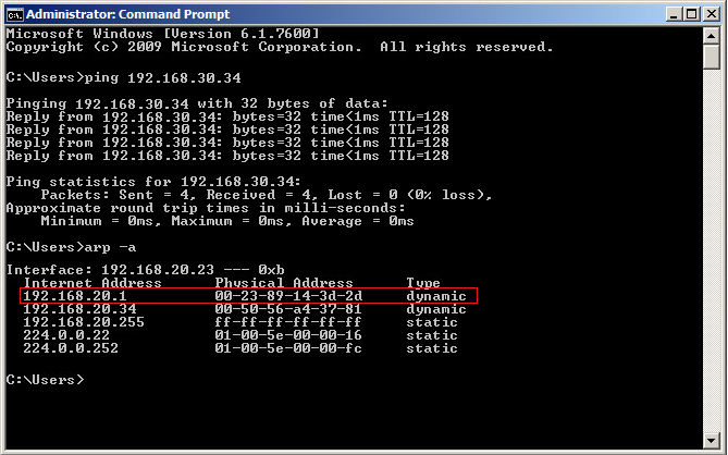
3. Display the gateway configuration of the PC and ping the remote host.
The gateway type of the PC is dynamic, and the PC and the remote host can ping each other, as shown in Figure 18.
Figure 18 Viewing the gateway information of the PC before the gateway spoofing attack
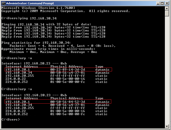
4. Simulate a gateway spoofing attack, and then display the gateway configuration of the PC.
The gateway configuration for the PC is changed, as shown in Figure 19.
Figure 19 Viewing the gateway information of the PC after the gateway spoofing attack
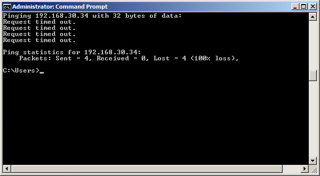
5. Ping the remote host again.
The PC and the remote host cannot ping each other, as shown in Figure 20.
Figure 20 The PC and the remote host cannot ping each other