- Released At: 05-07-2024
- Page Views:
- Downloads:
- Table of Contents
- Related Documents
-
|
H3C IMC UAM |
|
Device User Authentication Configuration Examples |
|
|
Software version: IMC UAM 7.2 (E0403)
|
Copyright © 2016 Hangzhou H3C Technologies Co., Ltd. All rights reserved. No part of this manual may be reproduced or transmitted in any form or by any means without prior written consent of Hangzhou H3C Technologies Co., Ltd. The information in this document is subject to change without notice. |
|
Introduction
This document provides examples for configuring authentication for a device user.
The examples apply to scenarios where a device user must pass identity authentication before logging in to devices through Telnet.
Example: Configuring device user authentication
Network configuration
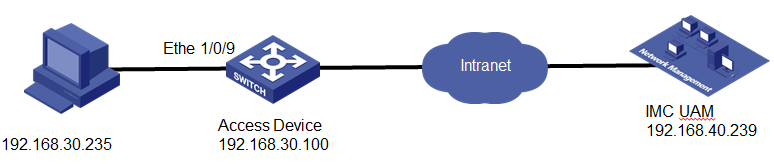
As shown in Figure 1, a device user wants to Telnet to the switch from a PC.
Configure IMC UAM and the switch so that the device user can pass identity authentication and log in to the switch.
Software version used
This configuration example was created and verified on the following platforms:
· IMC UAM 7.2 (E0403)
· H3C S3600V2-28TP-EI Comware Software, Version 5.20, Release 2103
Configuring UAM
Configuring the switch as an access device
2. From the navigation tree, select User Access Policy > Access Device Management > Access Device.
3. Click Add.
The Add Access Device page opens.
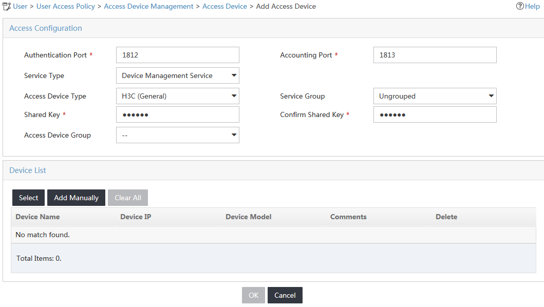
4. Configure the access configuration parameters for the access device, as shown in Figure 2:
a. Enter 1812 in the Authentication Port field.
The default authentication port is 1812.
b. Enter 1813 in the Accounting Port field.
The default accounting port is 1813.
c. Select Fully Supported from the RADIUS Accounting list.
d. Select Device Management Service from the Service Type list.
e. Select H3C(General) from the Access Device Type list.
f. Use the default setting for Access Device Group.
g. Enter and confirm the shared key in the Shared Key and Confirm Shared Key fields. Make sure the value is the same as the key configured on the access device.
h. Use the default setting for Service Group.
Figure 2 Adding the switch to UAM as an access device
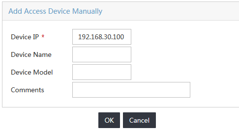
5. In the Device List area, click Add Manually.
The Add Access Device Manually dialog box opens.
6. Configure the access device parameters, as shown in Figure 3:
a. In the Start IP and End IP fields, specify the IP address range in which the switch is located.
- If the nas ip command is configured on the switch, enter the NAS IP address in the Start IP field.
- If the command is not configured on the switch, enter the IP address of the port that connects the switch to UAM in the Start IP field.
This example uses 192.168.30.100.
b. Enter a description for the access device in the Comments field.
Figure 3 Adding an access device
7. Click OK to return to the Add Access Device page.
8. Click OK.
Adding the device user to UAM
1. Click the User tab.
2. From the navigation tree, select Access User > Device User > Device User.
The Device User page opens, as shown in Figure 4.
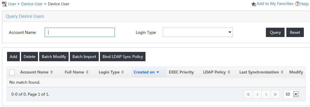
3. Click Add.
The Add Device User page opens.
4. Configure the following parameters, as shown in Figure 5:
a. Enter the login name of the device user in the Account Name field.
b. Enter and confirm the login password for the device user in the User Password and Confirm Password fields.
c. Select Telnet from the Service Type list.
d. Enter 3 in the EXEC Priority field.
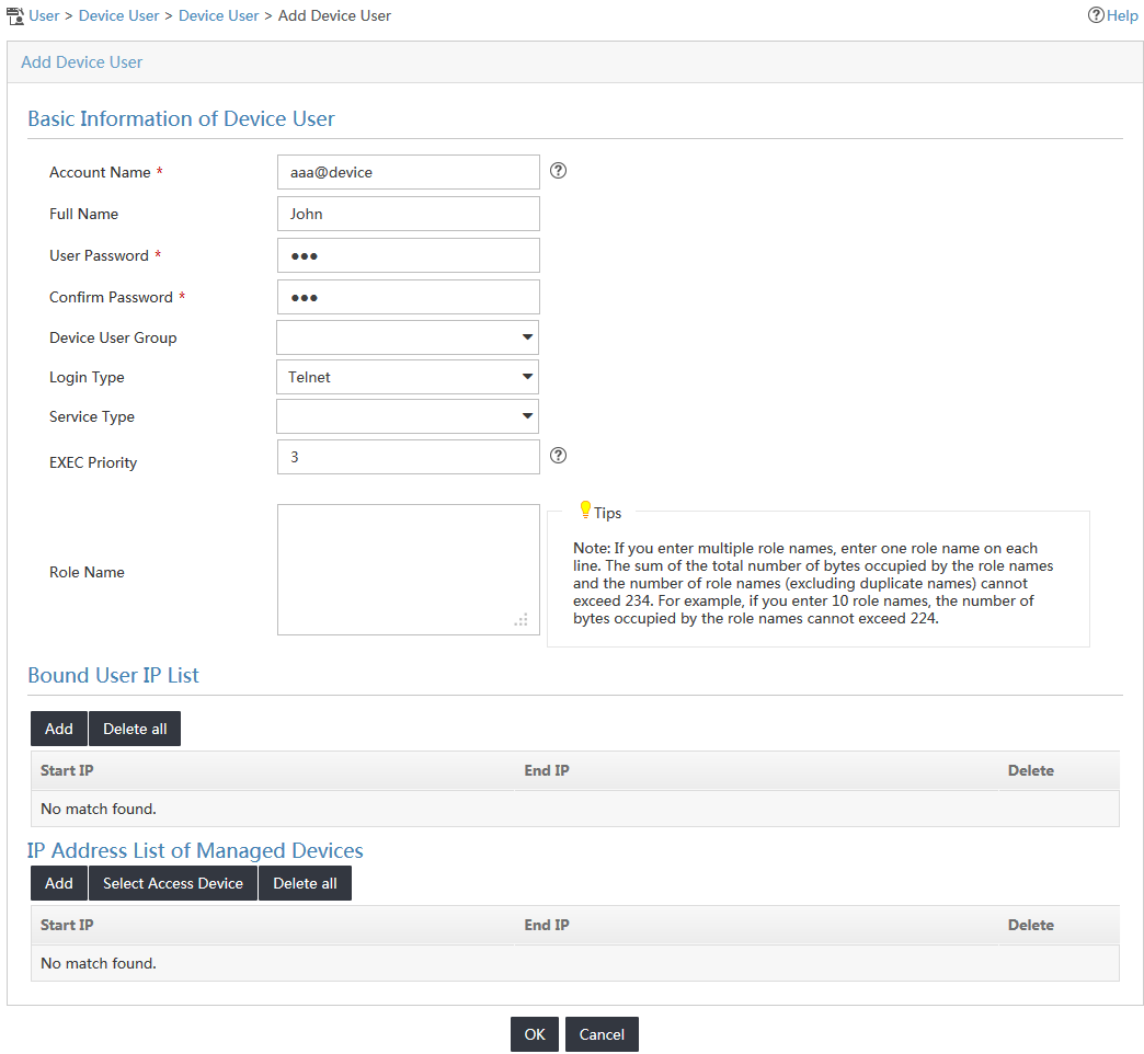
5. In the Bound User IP List area, click Add.
6. On the Add IP Address page, enter 192.168.30.230 as the start IP address and 192.168.30.235 as the end IP address, as shown in Figure 6.
The device user can only log in to a device by using a terminal whose IP address is in the specified bound user IP address range.
Figure 6 Adding a bound user IP address range

7. Click OK.
8. Click Add in the IP Address List of Managed Devices area.
The Add IP Address dialog box opens.
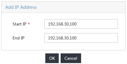
9. Enter 192.168.30.100 in both the Start IP Address and End IP Address fields, as shown in Figure 7.
The device user can only manage devices in the specified IP address range. In this example, the device user can only manage the access device whose IP address is 192.168.30.100.
Figure 7 Adding an IP address range for managed devices
10. Click OK to return to the Add Device User page.
11. Click OK.
Configuring AAA on the switch
1. Telnet to the switch from the Windows CLI.
2. Configure the switch to perform AAA authentication for Telnet users.
[H3C]user-interface vty 0 4
[H3C-ui-vty0-4]authentication-mode scheme
[H3C-ui-vty0-4]quit
3. Create a RADIUS scheme named 391:
# Specify UAM as the RADIUS server, configure the authentication port, accounting port, keys, and the nas-ip according to the device settings in UAM.
[H3C]radius scheme 391
New Radius scheme
[H3C-radius-391]primary authentication 192.168.40.239 1812
[H3C-radius-391]primary accounting 192.168.40.239 1813
[H3C-radius-391]key authentication 123
[H3C-radius-391]key accounting 123
[H3C-radius-391]nas-ip 192.168.30.100
[H3C-radius-391]server-type extended
# Specify the username format.
[H3C-radius-391]user-name-format with-domain
[H3C-radius-391]quit
In this example, the user-name-format with-domain command is configured on the access device. As a result, usernames entered on the iNode client must carry the domain information. Table 1 lists the rules that indicate how IMC UAM cooperates with the access device (the switch) to authenticate Telnet users.
Table 1 RADIUS configurations on the access device
|
Username format on the iNode client |
Domain on the access device |
Username format configured on the access device |
Service suffix in UAM |
|
X@Y |
Y |
user-name-format with-domain |
Y |
|
user-name-format without-domain |
No suffix |
||
|
X |
[Default Domain] The default domain specified on the access device |
user-name-format with-domain |
Name of the default domain |
|
user-name-format without-domain |
No suffix |
4. Create a domain and reference RADIUS scheme 391 in the domain.
[H3C]domain device
New Domain added
[H3C-isp-device]authentication login radius-scheme 391
[H3C-isp-device]authorization login radius-scheme 391
[H3C-isp-device]accounting login radius-scheme 391
[H3C-isp-device]quit
Verifying the configuration
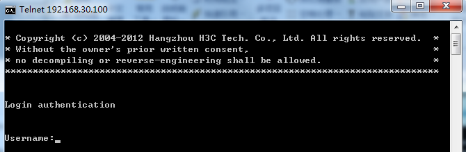
1. Telnet to the switch, as shown in Figure 8.
Figure 8 Telnetting to the switch
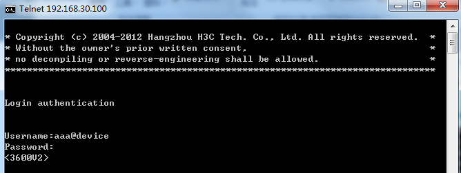
2. Enter the username and password configured for the device user in UAM to log in to the switch, as shown in Figure 9.
Figure 9 Entering the username and password
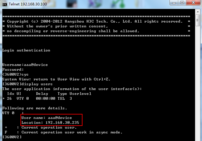
3. Execute the display users command to view detailed information about the device user.
As shown in Figure 10, the IP address of the user terminal is 192.168.30.235, which is within the specified bound user IP address range. The user level is 3, the same as it is configured in UAM.
Figure 10 Displaying user information