01-H3C IMC UAM 802.1X Access Control and RSA Authentication Configuration Examples-book.pdf(1.08 MB)
- Released At: 05-07-2024
- Page Views:
- Downloads:
- Table of Contents
- Related Documents
-
|
H3C IMC UAM |
|
802.1X Access Control and RSA Authentication Configuration Examples |
|
|
Software version: IMC UAM 7.2 (E0403)
|
Copyright © 2016 Hangzhou H3C Technologies Co., Ltd. All rights reserved. No part of this manual may be reproduced or transmitted in any form or by any means without prior written consent of Hangzhou H3C Technologies Co., Ltd. The information in this document is subject to change without notice. |
|
Contents
Example: Using UAM to implement RSA authentication for users
Configuring an access policy for RSA authentication
Associating an access service with the access policy
Configuring third-party authentication
Adding a user and assigning a token to the user
Configure UAM as a RADIUS client and RSA agent
Checking the authentication port
Triggering 802.1X authentication in the iNode client
Introduction
This document provides examples for configuring UAM to work with an RSA server to authenticate users.
The examples apply to systems that use dynamic passwords in authentication requests (for example, bank systems).
Prerequisites
Make sure the iNode client supports RSA dynamic keys.
Example: Using UAM to implement RSA authentication for users
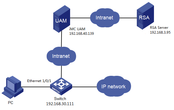
Network configuration
As shown in Figure 1, a user accesses a bank's network through the iNode client on a Windows PC. UAM forwards the user's authentication requests to an RSA server.
UAM uses the authentication port number 1812, the accounting port number 1813, and the shared key fine for RADIUS communication.
The RSA server listens to port number 1812 and uses the key mytest for RADIUS communication.
The switch manages the user in an ISP domain named 629 and includes the domain information in the usernames to be sent to UAM.
The user obtains an RSA SecurID token and uses an account named rose for network access.
Analysis
To use UAM and the RSA server for authentication, RSA authentication and the RSA server must be configured on UAM. UAM must be configured as a RADIUS client of the RSA server.
Software versions used
This configuration example was created and verified on the following platforms:
· IMC UAM 7.2 (E0403)
· H3C S5500-28C-SI Comware Software, Version 5.20, Release 2215
· iNode PC 7.2 (E0403)
Restrictions and guidelines
When you configure an access device or an access service in UAM, follow these restrictions and guidelines:
· Make sure the shared key configured for the access device is the same as the shared key in the CLI configuration on the switch.
· Make sure the authentication and accounting port numbers configured for the access device are the same as those in the CLI configuration on the switch.
· Configure the device IP address for the access device by using one of the following methods:
¡ If you have configured the nas-ip command for the RADIUS scheme on the device, configure the NAS IP address as the access device address in UAM.
¡ If you do not configure the nas-ip command for the RADIUS scheme, enter the IP address of the device's interface that connects to UAM for the access device.
¡ When the switch is selected from the resource pool, the IP address is automatically populated for the access device. If the IP address is incorrect, the switch must be manually configured.
· Configure a service suffix for the 802.1X user depending on the authentication domain and username format settings on the switch, as shown in Table 1.
Table 1 Determining the service suffix
|
Username in iNode |
Authentication domain on the switch |
Username format command on the switch |
Service suffix in UAM |
|
rose@629 |
629 |
user-name-format with-domain |
629 |
|
user-name-format without-domain |
No suffix |
Configuring UAM
Adding the switch to UAM
1. Click the User tab.
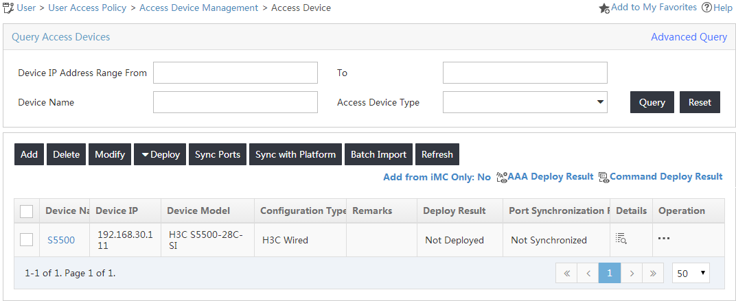
2. From the navigation tree, select User Access Policy > Access Device Management > Access Device.
The Access Device page opens, as shown in Figure 2.
Figure 2 Accessing the Access Device page
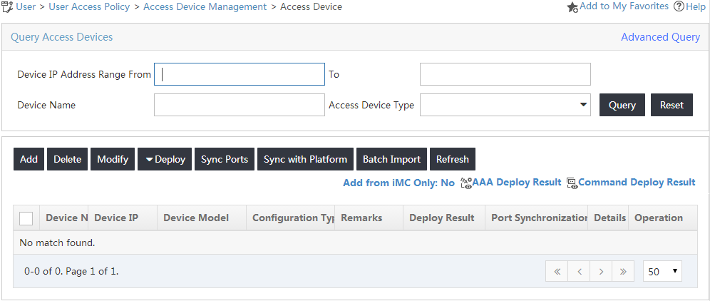
3. Click Add on top of the access device list.
The Add Access Device page opens, as shown in Figure 3.
Figure 3 Adding an access device
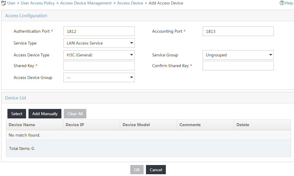
4. Configure the access device parameters:
a. In the Access Configuration area, enter fine in the Shared Key and Confirm Shared Key fields and use the default values for other parameters.
If Display Access Passwords is set to Plain Text (display password) in system settings, the Confirm Shared Key field is not available.
b. In the Device List area, perform one of the following tasks:
- Click Select to select the switch from the resource pool, as shown in Figure 4. (Details not shown.)
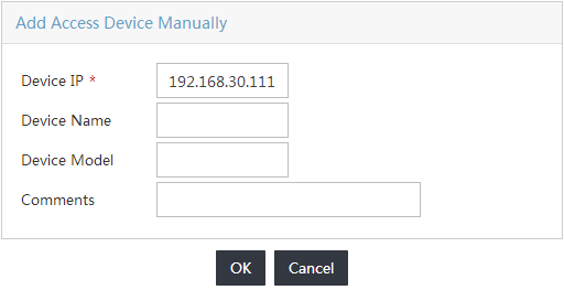
- Click Add Manually to add the switch to UAM, as shown in Figure 5. (Details not shown.)
Figure 4 Selecting an access device

Figure 5 Adding an access device manually
5. Click OK.
The new access device is added to the access device list, as shown in Figure 6.
Figure 6 Viewing the new access device
Configuring an access policy for RSA authentication
1. Click the User tab.
2. From the navigation tree, select User Access Policy > Access Policy.
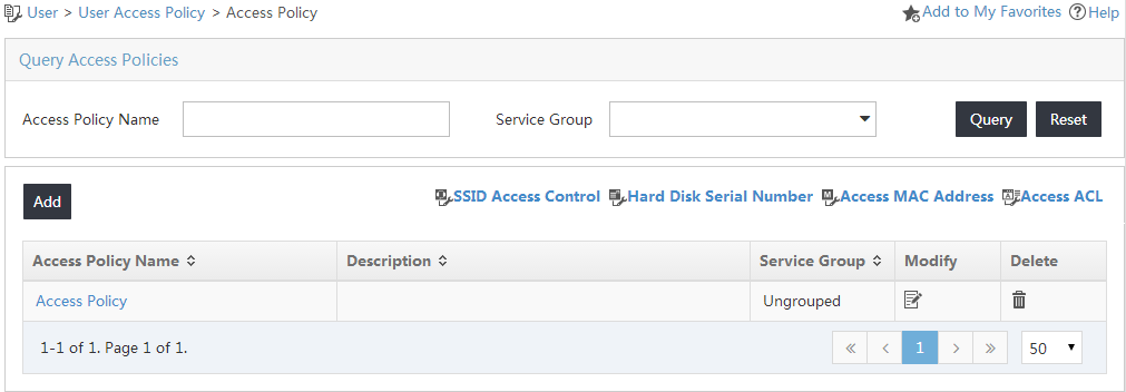
The Access Policy page opens, as shown in Figure 7.
Figure 7 Accessing the Access Policy page
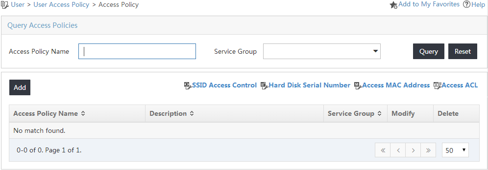
3. On the access policy list, click Add.
The Add Access Policy page opens.
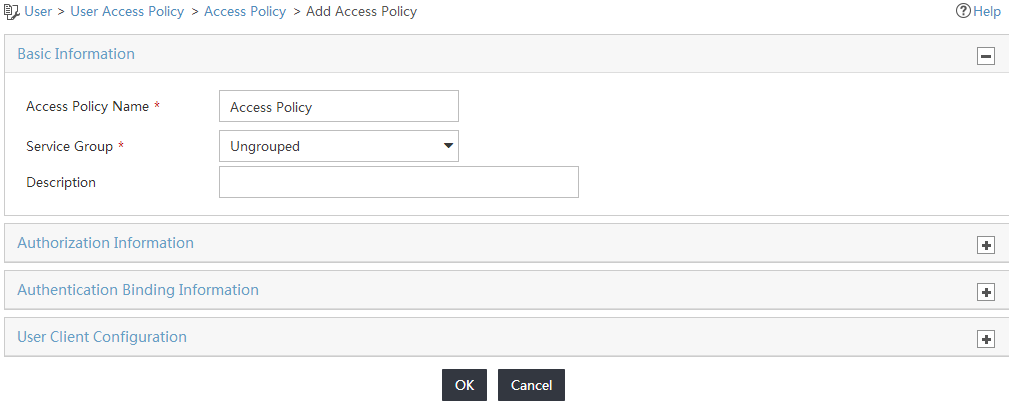
4. Configure the policy parameters, as shown in Figure 8:
a. In the Basic Information area, enter Access Policy in the Access Policy Name field.
b. Use the default values for other parameters.
Figure 8 Adding an access policy
5. Click OK.
The new access policy is added to the access policy list, as shown in Figure 9.
Figure 9 Viewing the new access policy
Associating an access service with the access policy
1. Click the User tab.
2. From the navigation tree, select User Access Policy > Access Service.
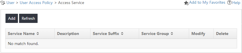
The Access Service page opens, as shown in Figure 10.
Figure 10 Accessing the Access Service page
3. On the access service list, click Add.
The Add Access Service page opens.
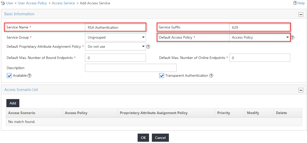
4. Configure the access service parameters, as shown in Figure 11:
a. Enter RSA Authentication in the Service Name field.
b. Enter 629 in the Service Suffix field. For more information about determining the service suffix, see Table 1.
c. Select Access Policy from the Default Access Policy list.
d. Use the default values for other parameters.
Figure 11 Adding an access service
5. Click OK.
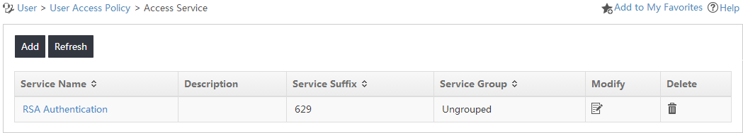
The new access service is added to the access service list, as shown in Figure 12.
Figure 12 Viewing the new access service
Configuring third-party authentication
1. Click the User tab.
2. From the navigation tree, select User Access Policy > Third-Party Authentication.
The Third-Party Authentication page opens, as shown in Figure 13.
Figure 13 Accessing the Third-Party Authentication page

3. Click the Configure
icon ![]() in the Action column for the third-party authentication policy.
in the Action column for the third-party authentication policy.
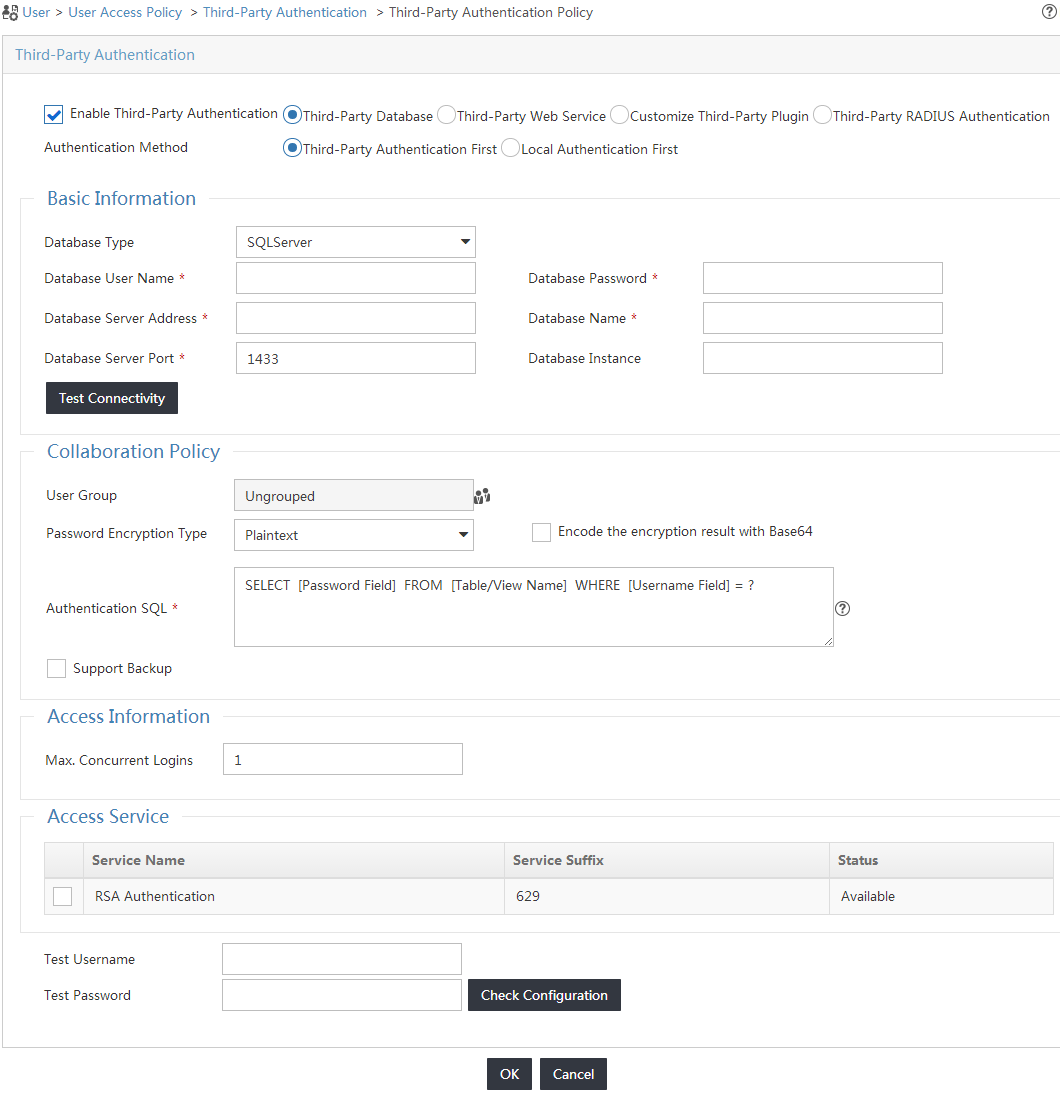
The Third-Party Authentication Policy page opens, as shown in Figure 14.
Figure 14 Accessing the Third-Party Authentication Policy page
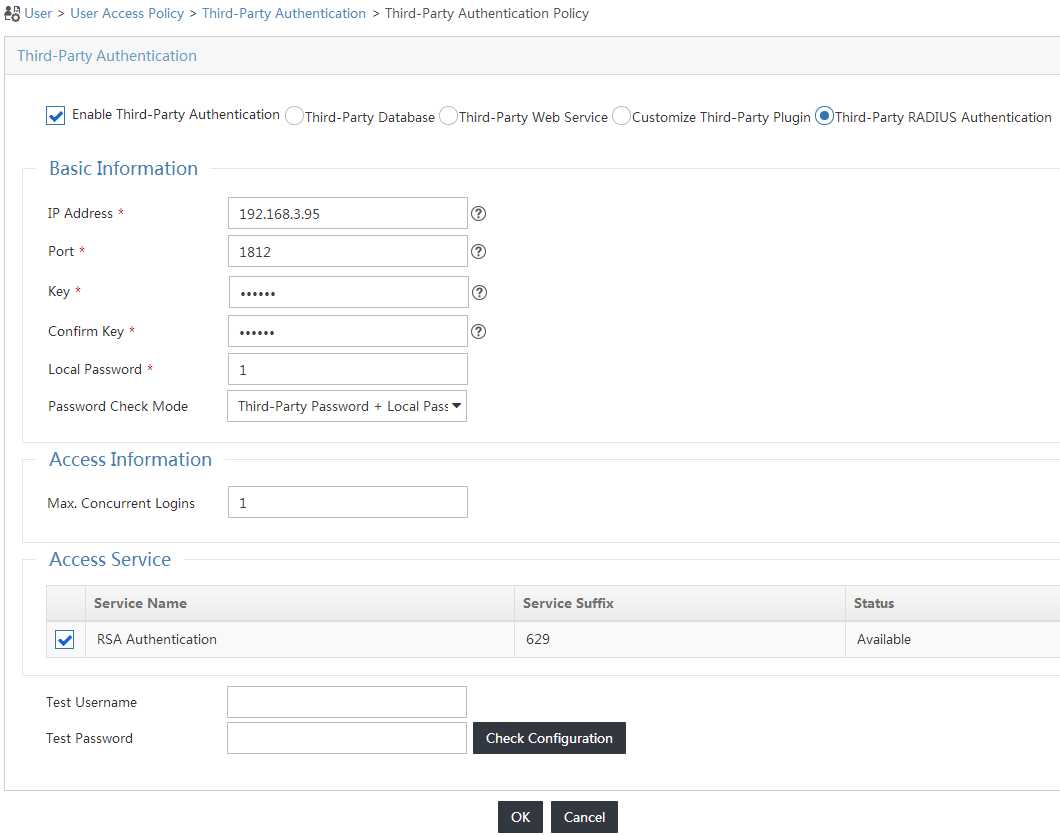
4. Configure parameters for the third-party authentication policy, as shown in Figure 15:
a. Select the Enable Third-Party Authentication option, and then select Third-Party RADIUS Authentication.
b. Configure the basic information:
- Enter 192.168.3.95 in the IP Address field.
- Enter the listening port number 1812 for RSA authentication in the Port field.
- Enter mytest in the Key and Confirm Key fields.
- Enter 1 in the Local Password field.
- Select Third-Party Password + Local Password from the Password Check Mode list.
c. In the Access Service area, select access service RAS Authentication.
Figure 15 Configuring the third-party authentication policy
5. Click OK.
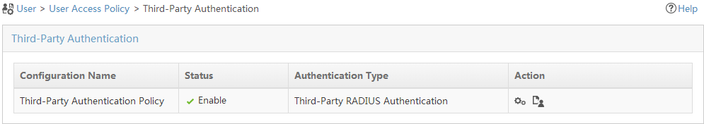
The enabled third-party authentication policy opens in the third-party authentication list, as shown in Figure 16.
Figure 16 Viewing the enabled third-party authentication policy
Configuring the switch
1. Configure a RADIUS scheme:
# Create a RADIUS scheme named zzpermit.
<H3C>system-view
System View: return to User View with Ctrl+Z.
[H3C]radius scheme zzpermit
New Radius scheme
# Configure UAM as the primary RADIUS authentication and accounting servers in the scheme. Set the RADIUS authentication port to 1812 and the accounting port to 1813.
[H3C-radius-zzpermit]primary authentication 192.168.40.139 1812
[H3C-radius-zzpermit]primary accounting 192.168.40.139 1813
# Configure the shared key to fine to secure RADIUS authentication and accounting communication.
[H3C-radius-zzpermit]key authentication fine
[H3C-radius-zzpermit]key accounting fine
# Configure the switch to include domain information in the usernames to be sent to the RADIUS server.
[H3C-radius-zzpermit]user-name-format with-domain
[H3C-radius-zzpermit]quit
2. Configure an ISP domain:
# Add an ISP domain named 629.
[H3C]domain 629
New Domain added.
# Configure the switch to use the RADIUS scheme zzpermit for users in ISP domain 629.
[H3C-isp-629]authentication lan-access radius-scheme zzpermit
[H3C-isp-629]authorization lan-access radius-scheme zzpermit
[H3C-isp-629]accounting lan-access radius-scheme zzpermit
[H3C-isp-629]quit
3. Configure 802.1X authentication:
# Enable 802.1X globally and on Ethernet 1/0/1. The 802.1X function takes effect on the interface only when 802.1X is enabled globally and on the interface.
[H3C]dot1x
802.1X is enabled globally.
[H3C]dot1x interface Ethernet 1/0/1
802.1X is enabled on port Ethernet1/0/1.
# Set the 802.1X authentication method. With RSA authentication, you can set the 802.1X authentication method to PAP only.
[H3C]dot1x authentication-method pap
PAP authentication is enabled.
Configuring the RSA server
Adding a user and assigning a token to the user
1. Log in to the RSA security console on the RSA server.
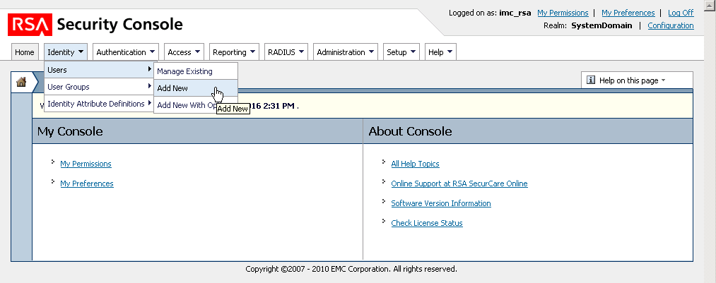
2. Select Identity > Users > Add New, as shown in Figure 17.
3. Add a user named rose and set a password for the user, as shown in Figure 18. (Details not shown.)

4. Assign a token to the user by using one of the following methods:
Method 1
a. Select Identity > Users > Manage Existing.
b. Click the Expand icon ![]() next to user rose, select SecurID Tokens
from the menu, and then select a token for the user.
next to user rose, select SecurID Tokens
from the menu, and then select a token for the user.
Method 2
a. Select Authentication > SecurID Tokens > Manage Existing > Unassigned.
b. Click the Expand icon ![]() next
to a token, select Assign to User from the menu, and then select user rose.
next
to a token, select Assign to User from the menu, and then select user rose.
Configure UAM as a RADIUS client and RSA agent
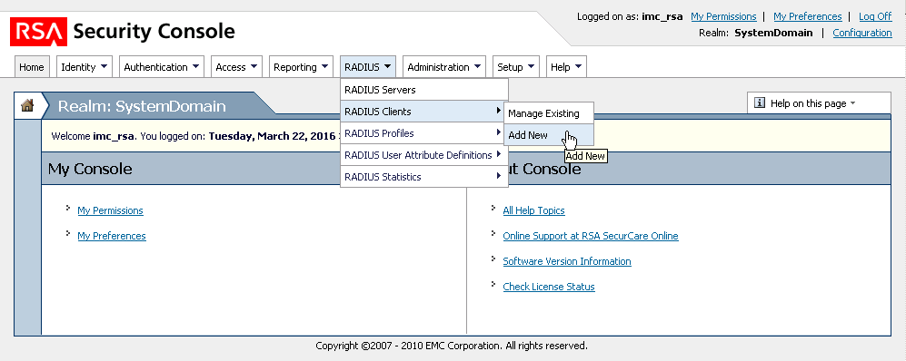
1. Select RADIUS > RADIUS Clients > Add New, as shown in Figure 19.
Figure 19 Adding a RADIUS client
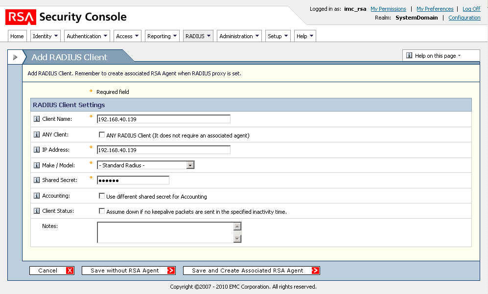
2. Configure the RADIUS client parameters, as shown in Figure 20.
a. In the Client Name field, enter a name for the client. This example uses the IP address of the UAM server as the client name.
b. In the IP Address field, enter the IP address of the UAM server.
c. In the Shared Secret field, enter the shared key mytest to match the key for RSA authentication in UAM.
d. Use the default values for other parameters.
Figure 20 Configuring UAM as a client
3. Click Save and Create Associated RSA Agent.
The page for adding an RSA agent opens, as shown in Figure 21. This RSA agent is associated with the newly added client.
Figure 21 Adding an RSA agent
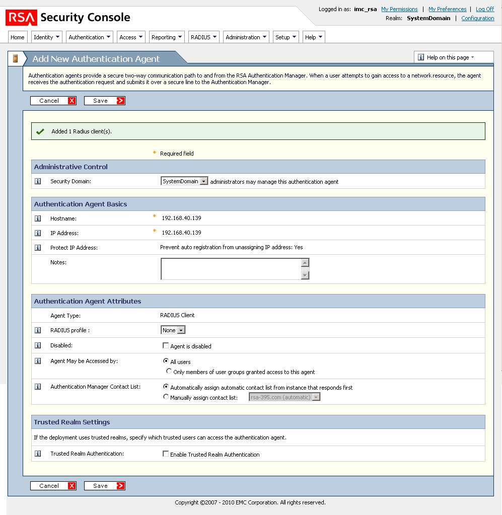
4. Click Save.
The new authentication agent is created.
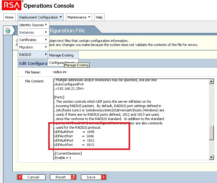
Checking the authentication port
Make sure the UDP authentication port is 1812, which matches the port used by UAM, as shown in Figure 22. (Details not shown.)
Figure 22 Checking the UDP authentication port
Verifying the configuration
Triggering 802.1X authentication in the iNode client
1. On the iNode client, click 802.1X Connection.
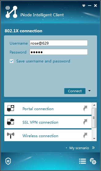
The 802.1X Connection window opens, as shown in Figure 23.
Figure 23 Accessing the 802.1X Connection area

2. Click the More icon ![]() in
the 802.1X connection area and select Properties, as shown in Figure 24.
in
the 802.1X connection area and select Properties, as shown in Figure 24.
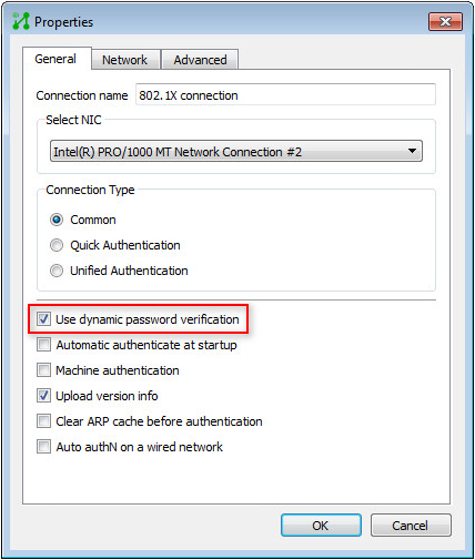
Figure 24 802.1X connection properties

3. On the Properties window, select Use dynamic password verification and click OK, as shown in Figure 25.
Figure 25 Enabling dynamic password verification
In the 802.1X Connection window, enter the username and password, and click Connect, as shown in Figure 26.
Figure 26 Triggering 802.1X authentication
4. Verify that the connection can be successfully established, as shown in Figure 27.
Figure 27 Viewing the authentication result

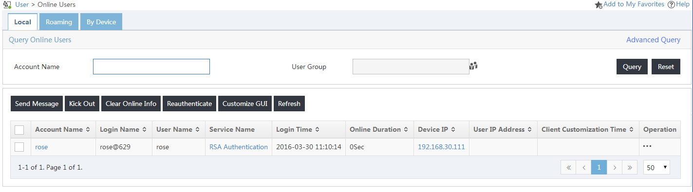
Viewing online users in UAM
1. Click the User tab.
2. From the navigation tree, select Access User > Online Users.
3. On the Local tab, verify that user rose has been added to the online user list, as shown in Figure 28.
Figure 28 Viewing the online user list