- Released At: 31-07-2025
- Page Views:
- Downloads:
- Table of Contents
- Related Documents
-
|
|
|
H3C Wireless Products |
|
Troubleshooting Guide |
Copyright © 2024 New H3C Technologies Co., Ltd. All rights reserved.
No part of this manual may be reproduced or transmitted in any form or by any means without prior written consent of New H3C Technologies Co., Ltd.
Except for the trademarks of New H3C Technologies Co., Ltd., any trademarks that may be mentioned in this document are the property of their respective owners.
The information in this document is subject to change without notice.
Contents
Collecting log and operating information
Collecting common log messages
Collecting diagnostic log messages
Collecting operating statistics
Function error after software upgrade
Unable to log in to the local Web interface of a cloud-managed AP
Unexpected reboot of some APs powered by a PoE switch
No output on the console and the power LED is off
No output on the terminal screen after power-on
Connection failure of network ports
Power failure of APs powered by a power adapter together with a PoE-MH port lightning protector
Weak wireless signals from an AP
AP interface communication anomaly
An AP is disconnected from the AC when local forwarding is enabled
Master/backup AC switch-back failure
The portal authentication page does not open when remote portal authentication is used
An AP can establish only a maximum of two mesh links
Mesh links frequently come up and go down
A client keeps roaming among APs
A client cannot actively roam to another AP
Remote 802.1X authentication failure
A client cannot associate with an AP again after going offline
A client stays in authentication status
Local 802.1X authentication failure
A client cannot come online when remote MAC and PSK authentication is used
A client cannot come online when local MAC and PSK authentication is used
An AP fails to associate with an AC because auto AP is disabled
Cloud-managed AP cannot connect to the cloud platform
WIPS countermeasures do not take effect
Remote AP function not effective
Access failure of new endpoint after the remote AP function is enabled
ACL deployment failure in 802.1X authentication
Wireless endpoint failure to obtain an IP address in centralized forwarding mode
A wireless client cannot obtain an IP in local forwarding mode
Troubleshooting non-device issues
A fit AP fails to obtain an IP address
A client associates with a weak-signal AP rather than a strong-signal and closer AP
Failure to configure wireless connection when WirelessZeroConfigure has been enabled
Failure to log in to the AC from the Web interface
Failure to modify auto-AP configuration
Failure to upgrade AP software by downloading images from the preconfigured location
Failure to automatically upgrade AP software through the AC
Failure to manually upgrade AP software from the BootWare menu
Unexpected disconnection of a fit AP
Random disconnection of a barcode scanner
Slow wireless NIC speed in centralized forwarding mode
Endpoint failure to automatically obtain IPv6 DNS information through RA messages
Endpoint failure to automatically obtain IPv6 DNS information through DHCPv6
Endpoint failure to automatically obtain an IPv6 address through stateless address configuration
Stateful address configuration fails for clients
Slow wireless rate under testing
Troubleshooting device startup
Garbled characters or no output at device startup
Reboot caused by device power recycling
Introduction
This document provides information about troubleshooting common software and hardware issues with H3C access controllers.
General guidelines
When you troubleshoot the access controller, follow these general guidelines:
· To help identify the cause of the issue, collect system and configuration information, including:
¡ Symptom, time of failure, and configuration.
¡ Network topology information, including the network diagram, port connections, and points of failure.
¡ Log messages and diagnostic information. For more information about collecting this information, see "Collecting log and operating information."
¡ Physical evidence of failure:
- Photos of the hardware.
- Status LEDs on the device, including power status LED, operating status LED, and port status LEDs.
¡ Steps you have taken, such as reconfiguration, cable swapping, and reboot.
¡ Output from the commands executed during the troubleshooting process.
· To ensure safety, wear an ESD wrist strap when you replace or maintain a hardware component.
· If hardware replacement is required, use the release notes to verify hardware and software compatibility.
· To prevent an issue from causing configuration loss, save the configuration each time you finish configuring a feature. For configuration recovery, regularly back up the configuration to a remote server.
Collecting log and operating information
|
|
IMPORTANT: By default, the information center is enabled. If the feature is disabled, you must use the info-center enable command to enable the feature for collecting log messages. |
Table 1 shows the types of files that the system uses to store operating log and status information. You can export these files by using FTP, TFTP, or USB.
To more easily locate log information, use a consistent rule to categorize and name files. For example, save log information files to a separate folder.
Table 1 Log and operating information
|
Category |
File name format |
Content |
|
Common log |
logfileX.log |
Command execution and operational log messages. X is available only when the device supports multiple log files of each file type. |
|
Diagnostic log |
diagfileX.log |
Debugging messages about device operation, including the following items: · Parameter settings in effect when an error occurs. · Information about a card startup error. · Handshaking information between the MPU and interface card when a communication error occurs. X is available only when the device supports multiple log files of each file type. |
|
Operating statistics |
filenameX.tar.gz |
Current operating statistics for feature modules, including the following items: · Device status. · CPU status. · Memory status. · Configuration status. · Software entries. · Hardware entries. X is available only when the device supports multiple log files of each file type. |
|
|
NOTE: · For devices that support only one log file of each category, the storage space for common log and diagnostic log is limited. If the storage space is full for such a log, the system uses the newly generated log messages to replace the oldest messages. · For devices that support multiple log files of each category, the size of each log file is limited. If more than one log file exists for a category, a number is added to each file name (for example, logfile1.log) to indicate the file generation order. When a file is full, the system compresses it into a .gz file, and then generates a new log file. When the maximum log file quantity for a log category is reached, the system deletes the oldest compressed file of the category and regenerates the log file with the same name to store new logs. · As a best practice, back up log files and compressed files in time to prevent important logs from being replaced. |
Collecting common log messages
1. Save common log messages from the log buffer to a log file.
<Sysname> logfile save
The contents in the log file buffer have been saved to the file cfa0:/logfile/logfile8.log
2. Identify the log files on the device:
<Sysname> dir cfa0:/logfile/
Directory of cfa0:/logfile
0 -rw- 21863 Jul 11 2018 16:00:37 logfile8.log
1021104 KB total (421552 KB free)
3. Transfer the files to the desired destination by using FTP, TFTP, or USB. (Details not shown.)
Collecting diagnostic log messages
1. Save diagnostic log messages from the diagnostic log file buffer to a diagnostic log file.
<Sysname> diagnostic-logfile save
The contents in the diagnostic log file buffer have been saved to the file cfa0:/diagfile/diagfile18.log
2. Identify the diagnostic log files on the device:
<Sysname> dir cfa0:/diagfile/
Directory of cfa0:/diagfile
0 -rw- 161321 Jul 11 2018 16:16:00 diagfile18.log
1021104 KB total (421416 KB free)
3. Transfer the files to the desired destination by using FTP, TFTP, or USB. (Details not shown.)
Collecting operating statistics
You can collect operating statistics by saving the statistics to a file or displaying the statistics on the screen.
When you collect operating statistics, follow these guidelines:
· Log in to the device through a network port or management port instead of the console port, if possible. Network and management ports are faster than the console port.
· Do not execute commands while operating statistics are being collected.
· As a best practice, save operating statistics to a file to retain the information.
To collect operating statistics:
1. Disable pausing between screens of output if you want to display operating statistics on the screen. Skip this step if you are saving statistics to a file.
<Sysname> screen-length disable
2. Collect operating statistics for multiple feature modules.
<Sysname> display diagnostic-information
Save or display diagnostic information (Y=save, N=display)? [Y/N] :
3. At the prompt, choose to save or display operating statistics:
# To save operating statistics, enter y at the prompt and then specify the destination file path.
Save or display diagnostic information (Y=save, N=display)? [Y/N] : Y
Please input the file name(*.tar.gz)[ cfa0:/diag_H3C_20180626-174139.tar.gz] :cfa0:/diag.tar.gz
Diagnostic information is outputting to cfa0:/diag.tar.gz.
Please wait...
Save successfully.
<Sysname> dir cfa0:/
Directory of cfa0:
…
6 -rw- 898180 Jun 26 2018 09:23:51 diag.tar.gz
1021808 KB total (259072 KB free)
# To display operating statistics on the monitor terminal, enter n at the prompt.
Save or display diagnostic information (Y=save, N=display)? [Y/N]:n
===============================================
===============display clock===============
17:26:39 UTC Wed 03/21/2018
=================================================
===============display version===============
H3C Comware Software, Version 7.1.064, Customer 5419
Copyright (c) 2004-2019 New H3C Technologies Co., Ltd. All rights reserved.
H3C WX5580H uptime is 0 weeks, 5 days, 6 hours, 17 minutes
Last reboot reason : User soft reboot
Boot image: cfa0:/boot.bin
Boot image version: 7.1.064, Customer 5419
Compiled Feb 01 2018 16:00:00
System image: cfa0:/system.bin
System image version: 7.1.064, Customer 5419
Compiled Feb 01 2018 16:00:00
Slot 1
Uptime is 0 week, 5 days, 6 hours, 17 minutes
with 1 1400MHz Multi-core Processor
32736M bytes DDR3
16M bytes NorFlash Memory
4002M bytes CFCard Memory
Hardware Version is Ver.A
CPLD 1 Version is 001
CPLD 2 Version is 002
FPGA1 Logic Version is 138
FPGA2 Logic Version is 138
Basic Bootrom Version is 5.07
Extend Bootrom Version is 5.15
[Subslot 0]WX5580H Hardware Version is Ver.A
===============display system internal version===============
H3C WX5580H V500R001B64D029SP19
Comware V700R001B64D029SP19
================================================
===============display device verbose===============
Slot No. Subslot No. Board Type Status Max Ports
1 0 WX5580H Normal 25
Slot 1
Status: Normal
Type: WX5580H
Hardware: A
Driver: 5.15
CPLD 1 CPLD: 001
CPLD 2 CPLD: 002
…
Documentation feedback
You can e-mail your comments about product documentation to [email protected].
We appreciate your comments.
Troubleshooting Web
This section provides troubleshooting information for common issues with Web.
Web login failure
Symptom
The system displays an error message indicating that the maximum number of Web users has been reached when a user logs in to the Web interface. The output from the display web users command shows that multiple Web users are online.
Solution
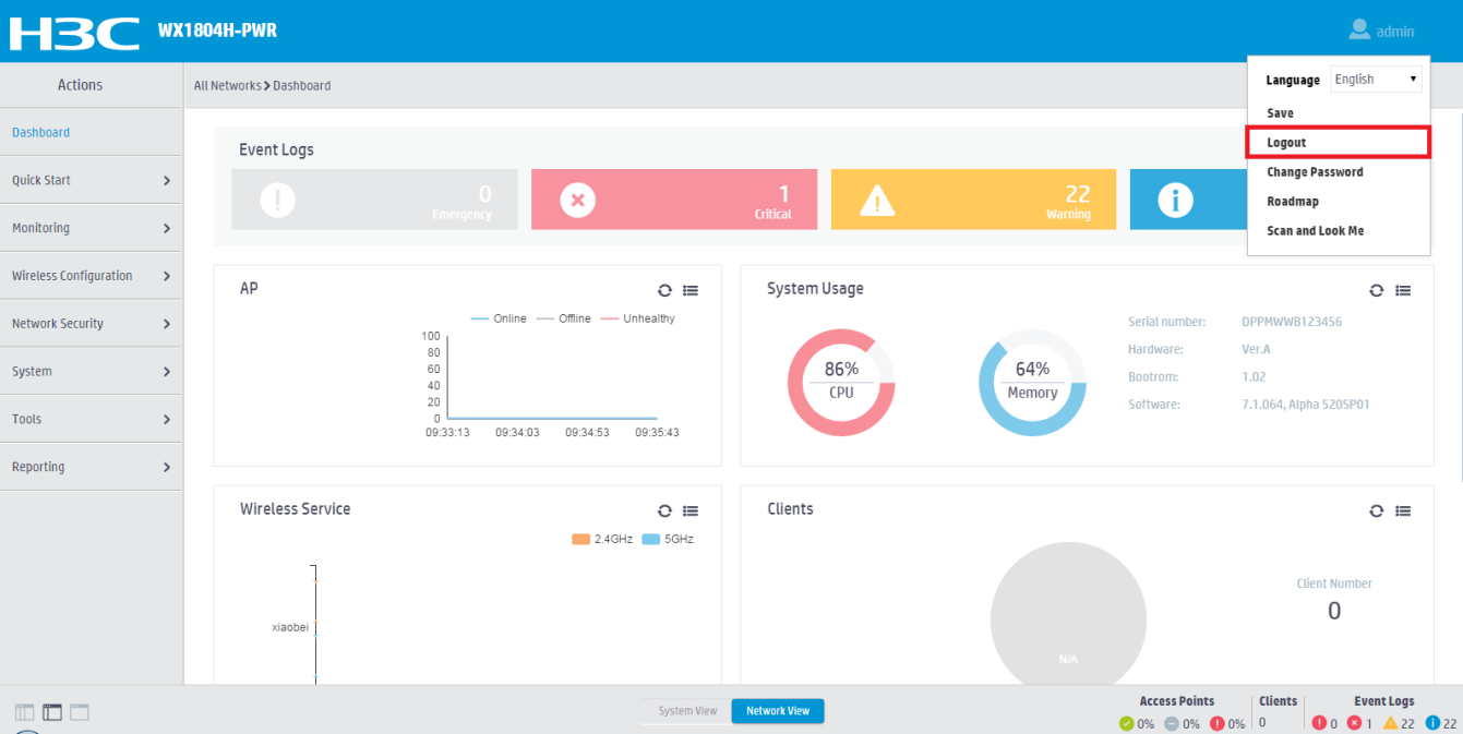
This symptom occurs when other users log out of the Web interface by directly closing the browser. To log out of the Web interface, you must click Logout in the upper-right corner of the Web interface, as shown in Figure 1.
Figure 1 Logging out of the Web interface
To resolve the issue:
1. Execute the free web users all command to forcibly log off all online Web users.
2. Log in to the Web interface again.
3. If the issue persists, contact Technical Support.
Function error after software upgrade
Symptom
The PC can ping the AC successfully and log in to the AC through Telnet after an AC software upgrade. However, the system prompts a function error when you log in to the Web interface again.
Solution
This issue is caused by uncleared cache of the browser. The cached information might be incompatible with the Web information for the new software version after a software upgrade.
To resolve the issue:
1. Launch the browser and clear its cache.
2. If the issue persists, contact Technical Support.
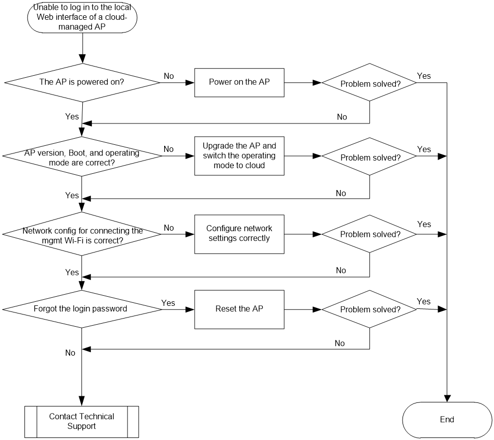
Unable to log in to the local Web interface of a cloud-managed AP
Symptom
The user cannot log in to the local Web interface of a cloud-managed AP.
Possible reasons
The common reasons of this issue include the following:
· The cloud-managed AP is not powered on. Wireless clients cannot detect the management Wi-Fi of the AP, resulting in inability to log in to local Web interface.
· The AP is not operating in cloud mode. Wireless clients cannot detect the management Wi-Fi of the AP, resulting in inability to log in to local Web interface.
· The wireless client is not connected to the management Wi-Fi of the cloud-managed AP, making it impossible to access the AP's local web interface.
Analysis
Figure 2 shows the diagnostic process of this type of fault.
Figure 2 Fault diagnosis flowchart
Solution
1. Verify that the cloud-managed AP is powered on.
You can quickly validate whether the device is powered on by using either of the following methods:
¡ Check the LED on the AP. When the LED is on (unless the LED is manually turned off), device is powered on. For more information about LED and AP states, see the AP installation manual.
|
|
NOTE: To obtain the device MAC address, remove the access panel or view the nameplate on the back of the device. |
¡ If the device is powered on, proceed to the next step.
2. Verify that the cloud AP is operating in cloud mode.
Some cloud-managed APs support multiple work modes. Make sure the AP is currently operating in cloud mode. If you can discover wireless service H3C_XXXXXX, where XXXXXX represents the last six digits of the device's MAC address through scanning, it indicates that the device is operating in cloud mode. Or, execute the display wlan device role command in any view on the device to view the device operating mode.
¡ If the device is not working in cloud mode, switch the operating mode to cloud. The supported working modes, methods of validating the current mode, and steps for switching modes may vary by device model. For more information, see the AP release notes. If the mode switch operation fails, cloud AP functions may become unavailable.
¡ If the device is operating in cloud mode, proceed to the next step.
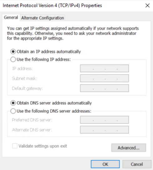
3. Check the network configuration of the wireless client.
Configure the wireless client to dynamically acquire IP addresses and DNS addresses.
Figure 3 Configuring a PC to automatically obtain an IP address
4. If you forgot the login password for the local Web interface, you can reset the password through the cloud platform if the device is connected to the platform. If the device is not connected to the cloud platform, you can use the reset button to restore the factory default settings and reset a password. For more information about using the reset button, see the AP installation guide. The local Web interface of a cloud-managed AP supports a maximum of five concurrent login users.
5. If the issue persists, collect the following information and contact Technical Support:
¡ The results of the aforementioned steps.
¡ The device's configuration files, log information, and alarm messages.
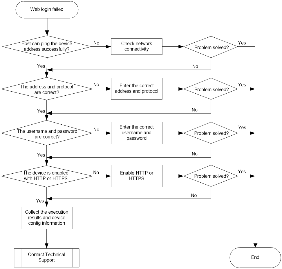
Device Web login failures
Symptom
The user cannot log in to the device login through the Web interface.
Possible reasons
The common reasons of this issue include the following:
· Network connection errors.
· Network link errors.
· Incorrect address.
· Incorrect username or password.
· HTTP or HTTPS not supported by the user.
· HTTP or HTTPS not enabled on the device.
Analysis
Figure 4 shows the diagnostic process of this type of fault.
Figure 4 Fault diagnosis flowchart
Solution
1. Verify if the host can ping the IP address of the device Web interface.
Use the ping command to check network connections.
If the ping operation fails, troubleshoot the network link.
¡ Physical link: For wired connections, check the network interface. For wireless connections, check the wireless NIC configuration.
¡ Logical link: If the host and device communicate at Layer 2, check if the host's address and the device's interface address are on the same network segment. If the host and the device communicate at Layer 3, verify if the host and device interface can reach each other.
2. Verify that the entered address and protocol are correct. The device supports both HTTP and HTTPS protocols. By default, HTTP is enabled and HTTPS is disabled. For example, on an AC, the correct address and protocol is http://192.168.0.100 or https://192.168.0.100.
3. Verify if the user's login username and password are correct. For an AC, both the default username and password are admin. For a fat AP, the default username and password are admin and h3capadmin, respectively.
¡ If a user-defined account is used, note that the password is case-sensitive and cannot contain spaces. If you still cannot log in, verify that the protocol type inputted in the browser matches the type of service set for the user. If they do not match, use the service-type command in local user view to add support for the protocol type inputted in the browser.
[AC-luser-manage-admin1]service-type https
¡ If you cannot use the default username and password to log in, enter the device CLI through the console port, and execute the display local-user command to verify if the local user named admin exists. If the user does not exist, create the user manually and enable support of HTTP or HTTPS service for the user.
<Sysname>display local-user
Device management user admin:
State: Active
Service type: HTTP/HTTPS
User group: system
Bind attributes:
Authorization attributes:
Work directory: flash:
User role list: network-admin
Password control configurations:
Password complexity: username checking
Total 1 local users matched.
Create a user and enable support or HTTP or HTTPS.
[Sysname]local-user abc class manage
New local user added.
[Sysname-luser-manage-abc]service-type http https
[Sysname-luser-manage-abc]
4. Verify if the device is enabled with HTTP or HTTPS. By default, the device is enabled with HTTP and disabled with HTTPS.
5. Use the display ip http or display ip https command.
[Sysname]display ip http
HTTP port: 80
ACL: 0
Operation status : Enabled
If the required service is disabled, enable the service.
[Sysname]ip http enable
[Sysname]ip https enable
6. If the issue persists, collect the following information and contact Technical Support:
The results of the aforementioned steps.
Device configuration information.
To collect device configuration information, use the display current-configuration command in user view.
<Sysname>display current-configuration
#
version 7.1.064, ESS 5452P05
#
clock timezone Beijing add 08:00:00
#
Troubleshooting hardware
This section provides troubleshooting information for common issues with hardware.
Unexpected reboot of some APs powered by a PoE switch
Symptom
Some of the APs powered by a PoE switch restart automatically and disconnect from the AC.
Solution
This symptom occurs when the PIs that power the APs are shut down. When the total power consumption exceeds the maximum power that can be provided by a PoE switch, the switch automatically disconnects the PIs with lower priorities.
The following log information shows the power supply condition of a switch:
#Apr 6 11:26:44:368 2019 YXY-WLAN-04 DRV_DEM/5/POE WARNING:- 1 -Power budget exceeded
#Apr 6 11:26:44:418 2019 YXY-WLAN-04 DRV_DEM/5/POE WARNING:- 1 -Poe function of Ethernet1/0/6 is disabled.
To resolve the issue:
1. Use more PoE switches to power the APs or use PoE modules to separately power some APs.
As a best practice, take power consumption in consideration when you plan the network.
2. If the issue persists, contact Technical Support.
No output on the console and the power LED is off
Symptom
When an AP is powered only by a power adapter, no output is displayed on the console and the power LED on the AP is off.
Solution
1. Verify that the input voltage of the power adapter is as required by the system.
2. Examine the AP to verify that the AP is not broken.
If the AP is broken, its internal components will be damaged and the AP cannot be powered on.
3. Verify that the AP is not wet and the operating temperature is as required.
An indoor AP cannot be powered on if used outdoors because the AP might get wet or the environmental temperature cannot meet the requirements. As a best practice, do not use indoor APs outdoor.
4. If the issue persists, contact Technical Support.
No output on the terminal screen after power-on
Symptom
After an AP is powered on, no output is displayed on the terminal screen when a serial port on the terminal is connected to an RJ-45 Ethernet port on the AP.
Solution
To resolve the issue:
1. Verify that the serial port on the terminal is connected to the console port on the AP. If the console cable is connected to a network port on the AP, reconnect it to the console port.
2. Verify that the following serial port settings are configured on the terminal:
¡ Baud rate—9600 bps.
¡ Data bits—8.
¡ Parity—None.
3. If the issue persists, contact Technical Support.
Connection failure of network ports
Symptom
After an AP is powered on, a network port of the AP cannot connect to other devices.
Solution
To resolve the issue:
1. Verify that the network cable is connected to the network port. If the network cable is connected to the console port, reconnect it to the network port.
2. Verify that the cable length is as required, for example, 100 m (328.08 ft). If the cable length exceeds the limit, replace the network cable.
3. Verify that the network cable is either a straight-through cable or a crossover cable.
Power failure of APs powered by a power adapter together with a PoE-MH port lightning protector
Symptom
An AP cannot be powered on through a power adapter and a PoE-MH port lightning protector.
Solution
To resolve the issue:
1. Verify that the network cable for power supply is correctly connected to RJ-45 (#2) on the PoE-MH port lightning protector.
Except for the power port that connects to the power adapter, the PoE-MH port lightning protector has two RJ-45 Ethernet ports, RJ-45 (#1) and RJ-45 (#2). RJ-45 (#1) is at the same side with the power port, and RJ-45 (#2) is at the opposite side. The network cable must be connected to RJ-45 (#2).
2. If the issue persists, contact Technical Support.
Fiber port link failure
Symptom
After a transceiver module is inserted into a fiber port, the fiber port operates incorrectly and output anomalies exist on the terminal screen.
Solution
To resolve the issue:
1. Reboot the device.
2. Verify that the Rx port and Tx port on the transceiver module are connected to the Rx port and Tx port on the peer end, respectively.
3. If the issue persists, contact Technical Support.
Weak wireless signals from an AP
Symptom
The wireless signal strength of an AP is weak.
Solution
To resolve the issue:
1. Verify that the internal and external antennas are configured correctly for the AP.
2. Verify that antennas are installed on the AP securely, and the 2.4 GHz and 5 GHz antennas are attached to the antenna ports correctly.
3. Use the max-power command to set the maximum power of the AP to its maximum.
4. If the issue persists, contact Technical Support.
AP power-on errors
Symptom
The AP cannot be powered on properly, and the AP LED cannot be turned on.
Possible reasons
The common reasons of this issue include the following:
· The output voltage or power of the power adapter or PoE injector does not meet the requirements.
· The PoE switch's output power does not meet the requirements.
· Hardware errors exist on the AP.
Analysis
Figure 5 shows the diagnostic process of this type of fault.
Figure 5 Fault diagnosis flowchart
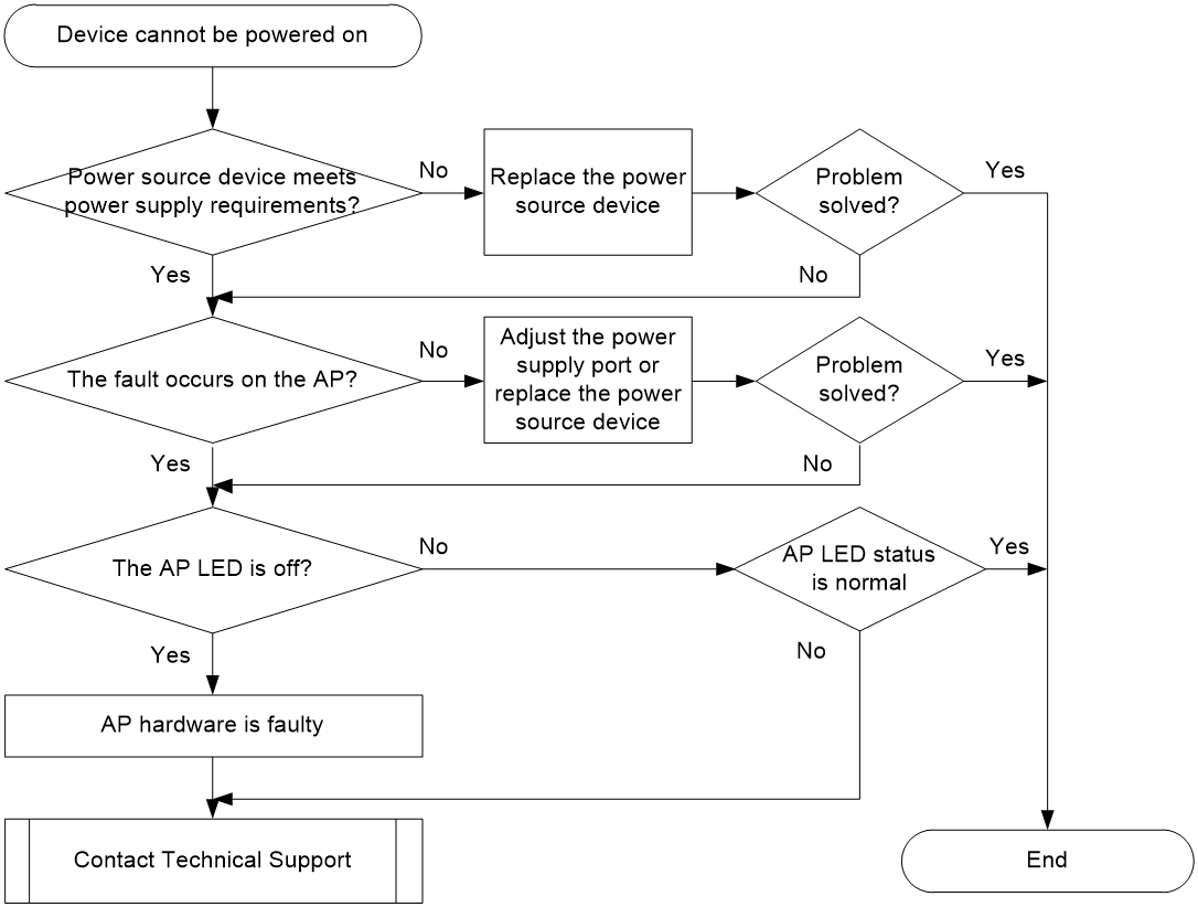
Solution
Power supply through power adapter or PoE injector
1. Verify if the power source equipment meets the power supply requirements.
If the AP is powered by an adapter or PoE injector, verify if the output power (voltage and electric) of the adapter or injector meets the voltage requirements in the AP installation manual.
¡If the requirement is not met, replace the power adapter or PoE injector.
¡If the issue still persists, proceed to the next step.
2. Locate faulty devices.
Use cross-testing to validate whether the fault lies in the power supply or the AP side.
¡Replace the power adapter or PoE injector with one of the same model for cross-testing. If the issue is resolved, the issue is most likely a power supply fault. Replace the power supply device.
¡Replace the AP with one of the same model for cross-testing. If the problem is resolved, it can be determined that the AP is faulty. Proceed to the next step.
3. Observe the AP LED status.
Use the LEDs to identify the AP status. For more information, see the installation guide for the AP.
¡If the power LEDs cannot be turned on, the issue is most likely an AP hardware fault. Contact Technical Support.
¡If the LEDs indicate an error, locate the faulty component and resolve the issue.
Power supply through PoE
1. Verify if the power source equipment meets the power supply requirements.
If AP is powered by PoE:
a. Verify if the power supply mode (PoE, PoE+, or PoE++) of the AP matches the power supply mode of the PoE switch.
b. Verify if the output power of a single port on the PoE switch meets the power requirements. Confirm if the total power of the APs connected to the PoE switch exceeds the power supply specification of the switch.
- If the power supply requirement is not met, replace the power source equipment.
- If the issue still persists, proceed to the next step.
2. Locate faulty devices.
Use cross-testing to validate whether the fault lies in the power supply or the AP side.
¡Use another power supply port or replace the PoE switch with one of the same mode. If the issue is resolved, the issue is most likely a PoE source fault. Switch to another power supply port or replace the power source device.
¡Replace the AP with one of the same model for cross-testing. If the problem is resolved, it can be determined that the AP is faulty. Proceed to the next step.
3. Observe the AP LED status.
Use the LEDs to identify the AP status. For more information, see the installation guide for the AP.
¡If the power LEDs cannot be turned on, the issue is most likely an AP hardware fault. Contact Technical Support or your sales agent to replace the faulty AP.
¡If the LEDs indicate an error, locate the faulty component and resolve the issue.
AP startup errors
Symptom
After the device is powered on, it cannot start up or restart repeatedly. For a single-LED AP, the LED is steady yellow. For a multi-LED AP, the power LED is steady yellow.
Possible reasons
The common reasons of this issue include the following:
· The startup file cannot be found.
· The startup file has encountered an anomaly.
· The memory has a fault.
· The BootWare section has a fault.
· Device hardware initialization occurred.
· Device self-check error is detected.
Analysis
For an AP that does not have a console port, you cannot check the startup process information of the AP. Restore the factory default settings and verify if the issue can be resolved.
For an AP that has a console port, log in to the device through the console port and verify if the AP can start up correctly. Figure 6 shows the diagnostic process of this type of fault.
Figure 6 Fault diagnosis flowchart
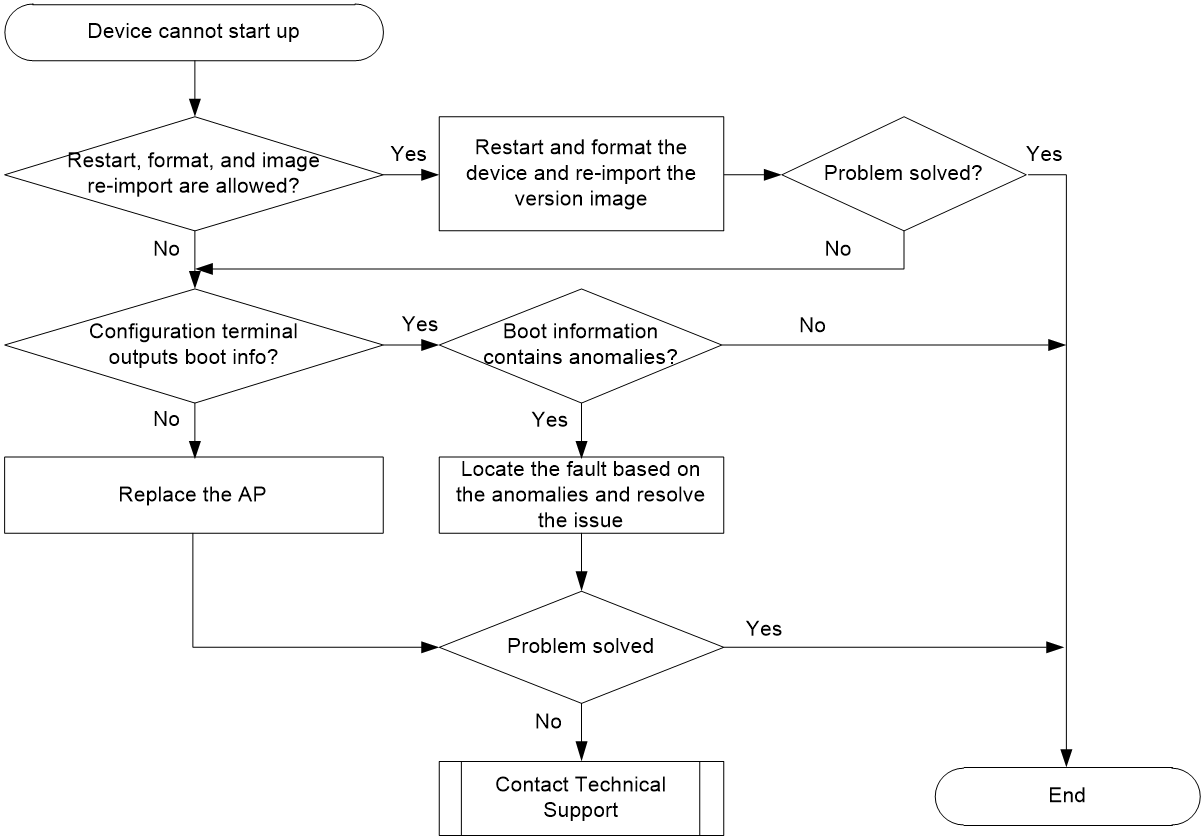
Solution
For an AP without a console port
Press the RESET button for over 5 seconds to restore the factory default settings. If the issue persists, contact Technical Support.
For an AP with a console port
1. If the AP encounters startup anomalies, within the scope of permitted operations, restart, format, and re-importing the version image as a best practice.
¡If the issue persists, see steps 2 and 3 to locate the error reason.
¡If you are unable to locate the error reason, collect the corresponding symptom and log information, and contact Technical Support.
2. Verify if the configuration terminal outputs startup information.
Connect the PC's serial port to the AP console port and power on the AP. Verify if the configuration terminal outputs startup information.
¡If the configuration terminal indicates that the AP starts but no startup information is output, replace the AP and network device. If the issue is resolved, the issue is most likely a fault in the AP hardware. Replace the AP as a best practice.
System is starting...
¡If the configuration terminal outputs AP startup information, proceed to the next step.
3. Verify if the startup information contains any anomalies.
After you power on the AP, the AP might fail to start up or restart repeatedly out of the following reasons:
¡The startup file cannot be found.
When the terminal displays the following startup information, it indicates that the image file cannot be found and the startup fails. In this case, restart the device and import the AP image file again.
BootWare Validating...
Press Ctrl+B to access EXTENDED-BOOTWARE MENU...
Loading the main image files...
The image does not exist!
Loading the backup image files...
¡The startup file has encountered an anomaly.
Startup file anomalies are typically caused by a file error or flash fault. Process Ctrl+B at the prompt to enter the BootWare main menu.
BootWare Validating...
¡Press Ctrl+B to access EXTENDED-BOOTWARE MENU...
¡In the BootWare main menu of BootWare, press Ctrl+F to format the flash and reload the boot file. If an error occurs during the formatting process, replace the AP as a best practice.
¡The memory has a fault.
¡The following prompt that appears during startup indicates a memory test failure:
System is starting...
Press Ctrl+D to access BASIC-BOOTWARE MENU
Value read :55555564;Value expected:55555555
DRAM test failed at:87FC0004
DRAM test failed at: 87fc0004
Fatal error! Please reboot the board.
As a best practice, restart the device and press Ctrl+D to enter the Basic BootWare menu. Then, press Ctrl+U and select RAM Test to perform a memory test. If the system prompts memory test failure, it indicates that a memory fault is present. Replace the AP as a best practice.
System is starting...
Press Ctrl+D to access BASIC-BOOTWARE MENU...
=====================<BASIC-BOOTWARE MENU (Ver 7.18) >======================
|<1> Modify Serial Interface Parameter
|<2> Update Extended BootWare
|<3> Update Full BootWare
|<4> Boot Extended BootWare
|<5> Boot Backup Extended BootWare
|<0> Reboot
============================================================================
Ctrl+U: Access BASIC ASSISTANT MENU
Enter your choice(0-5):
===========================<BASIC ASSISTANT MENU>===========================
|<1> RAM Test
|<0> Exit To Main Menu
============================================================================
Enter your choice(0-1): 1
Warning:Test Memory will take a long time? [Y/N]Y
Memory test......................................................
475 Mbytes memory has been tested.
Memory test failed.
¡The BootWare expansion section is missing.
¡If the configuration terminal does not prompt Press Ctrl+B to access EXTENDED-BOOTWARE MENU... after displaying Press Ctrl+D to access BASIC-BOOTWARE MENU..., and pressing Ctrl+B does not open the BootWare main menu interface, it indicates that the AP BootWare expansion section is missing.
System is starting...
Press Ctrl+D to access BASIC-BOOTWARE MENU...
Booting Normal Extend BootWare..
The Extend BootWare is self-decompressing............................Done!
When the terminal prompts Press Ctrl+D to access BASIC-BOOTWARE MENU, immediately press Ctrl+D to enter the basic BootWare menu. Then, enter 3 to restart the expansion section.
=====================<BASIC-BOOTWARE MENU (Ver 0.06) >======================
|<1> Modify Serial Interface Parameter |
|<2> Update Extended BootWare |
|<3> Update Full BootWare |
|<4> Boot Extended BootWare |
|<5> Boot Backup Extended BootWare |
|<0> Reboot |
============================================================================
Ctrl+U: Access BASIC ASSISTANT MENU
Ctrl+A: Enter Command Line
Ctrl+C: Display Copyright
Enter your choice(0-5): 3
Please Start To Transfer File, Press <Ctrl+C> To Exit.
Waiting ...C
Open the terminal software and select Xmodem in the menu bar to transmit data. For more information, see the upgrading BootWare menu section in the release notes of the device.
¡The hardware initialization failed.
If anomaly exit error message The process wloclited exited abnormally is output after the AP starts, it indicates that the hardware initialization failed. As a best practice, replace the AP.
¡Device self-check error is detected.
If the device outputs Fatal error at startup, it indicates that a device self-check error is present and the AP hardware is faulty. Replace the AP as a best practice.
AP input/output anomaly
Symptom
During the startup, the serial port does not output any information or output garbled characters. After the device starts up, commands cannot be entered.
Possible reasons
The common reasons of this issue include the following:
· The console cable is damaged.
· The serial port settings of the terminal emulation program are incorrect.
· The basic section of BootWare is damaged.
· The flash hardware fails.
Analysis
Figure 7 shows the diagnostic process of this type of fault.
Figure 7 Fault diagnosis flowchart
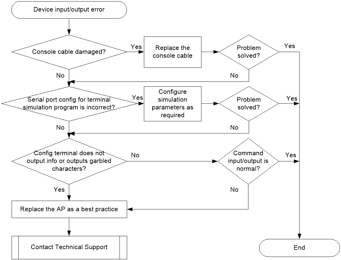
Solution
1. Verify that the console cable is not damaged.
2. Replace the cable connecting the computer to the console port of the device, and verify if the terminal can output information correctly.
¡If the issue is resolved, the console cable is damaged.
¡If the issue cannot be resolved, proceed to the next step.
3. Verify if the serial port configuration of the terminal emulation program has any errors.
Configure the terminal emulation parameters as follows: Baud rate: 9600, Data bits: 8, Stop bit: 1, Parity check: None, Traffic control: None.
If the issue persists, proceed to the next step.
4. If the configuration terminal does not output any information or outputs a garbled character line, the BootWare basic section is corrupted. Replace the AP as a best practice.
5. Verify if the command input and output are normal.
6. After the AP starts up, verify if the basic command input and output are normal. If the AP can output information but you cannot enter any string, use another AP for testing. If the issue can be resolved, the flash hardware of the old AP is faulty. Replace the AP as a best practice.
AP interface communication anomaly
Symptom
An AP starts up and is connected to a switch or other network devices through network cables, but it cannot communicate with the connected devices.
Possible reasons
The common reasons of this issue include the following:
· Communication anomaly on the AP wired interface.
· Link errors.
Analysis
If an AP has no console port or cannot be accessed through the console port, check the state of the AP uplink interface. This helps identify if the anomaly is caused by an Ethernet interface communication or interface state error.
For an AP with a console port, log in to the AP through the console port, and check the state of the AP uplink interface. This helps identify if the anomaly is caused by an Ethernet interface communication or interface state error.
Solution
Execute the display interface command multiple times to check the state of the physical interface and verify if the interface is in up state and if the number of incoming packets increases. To facilitate viewing, use the reset counter interface command to clear the existing packet statistics on the interface.
# View the status of the AP uplink interface.
<Sysname> display interface GigabitEthernet 1/0/1
GigabitEthernet1/0/1
Current state: UP
Line protocol state: UP
IP packet frame type: Ethernet II, hardware address: a4fa-7679-b6f0
...
Input (total): 196 packets, 21078 bytes
106 unicasts, 37 broadcasts, 53 multicasts, 0 pauses
Input (normal): 196 packets, 21078 bytes
106 unicasts, 37 broadcasts, 53 multicasts, 0 pauses
Input: 0 input errors, 0 runts, 0 giants, - throttles
0 CRC, - frame, 0 overruns, 0 aborts
- ignored, - parity errors
Output (total): 158 packets, 10179 bytes
157 unicasts, 0 broadcasts, 1 multicasts, 0 pauses
Output (normal): 158 packets, 10179 bytes
157 unicasts, 0 broadcasts, 1 multicasts, 0 pauses
Output: 0 output errors, 0 underruns, - buffer failures
- aborts, 0 deferred, 0 collisions, 0 late collisions
- lost carrier, - no carrier
For an AP that does not have a console port
· On the uplink device of the AP, use the display interface command to view the state of the interface connected to the AP.
· If the interface state is up, view the incoming packet statistics. If the broadcast packets in the inbound direction of the interface does not increase normally, replace the AP with another AP of the same model and perform the test again. If broadcast packets increases normally after the replacement, it can be determined that the old AP is faulty. Replace the AP as a best practice.
· If the peer interface of the AP cannot come up, check the wired interface state. For more information, see "Abnormal AP interface state."
For an AP that has a console port
· On the AP, use the display interface command to check the state of the uplink interface on the AP.
· If the interface state is up, check the outgoing packet statistics on the interface. If the broadcast packets in the outbound direction of the interface do not increase normally, it can be determined that communication errors occur on the AP Ethernet interface. Replace the AP as a best practice.
· If the uplink interface of the AP cannot come up, check the wired interface state. For more information, see "Abnormal AP interface state."
Abnormal AP interface state
Symptom
A device interface is operating incorrectly during AP operation. Common anomaly occurrences include:
· Use the display interface command to
¡view the physical interface status. The Current state field in the command output displays Down or Down (type).
¡Numerous error packets exist in the inbound and outbound directions on the interface.
· The wired interface comes up and goes down frequently.
Possible reasons
The common reasons of this issue include the following:
· Port configurations are incorrect.
· The interface configurations at both ends are inconsistent.
· Port traffic control is enabled.
· The link quality is poor.
· Common reasons for devices that support transceiver modules include:
· The transmit and receiving power of a fiber port is abnormal.
· The optoelectronic converter is faulty.
Analysis
Most interface errors that occur during device running can be identified by self-checking of the port or fiber interface.
Solution
1. View the interface Down reason.
Use the display interface command to check the state of the physical port, check if the port is down, and identify the down reason. For example, Current state: Administratively DOWN indicates that shutdown is configured in interface view and you must execute undo shutdown to bring up the interface.
<Sysname> display interface GigabitEthernet 1/0/1
GigabitEthernet1/0/1
Current state: Administratively DOWN
Common reasons of Down include:
¡Administratively DOWN: The interface was administratively shut down by the shutdown command.
¡DOWN: The management status of the interface is enabled but the physical status is disabled, which may occur due to no physical connection or line fault.
¡DOWN (Link-Aggregation interface down): The aggregate interface to which the interface belongs is shut down by the shutdown command.
¡mac-address moving down: The interface was shut down because of MAC address migration suppression.
¡STP DOWN: The interface was shut down because STP BPDU protection was triggered.
2. Check the duplex mode of interface negotiation link.
Use the display interface brief command to check the summary information of the interface.
¡In autonegotiation (A) state, the port rate and duplex mode are determined by automatic negotiation between the local and remote ports. The two ends require the consistent duplex rates.
¡In half duplex (H) state, you must check whether the interface configurations on both ends are inconsistent.
¡# View summary information of the interface.
<Sysname> display interface brief
The brief information of interface(s) under route mode:
Link: ADM - administratively down; Stby - standby
Protocol: (s) - spoofing
Interface Link Protocol Main IP Description
NULL0 UP UP(s) --
Vlan1 UP UP 192.168.1.254
Vlan2 UP UP --
The brief information of interface(s) under bridge mode:
Link: ADM - administratively down; Stby - standby
Speed or Duplex: (a)/A - auto; H - half; F - full
Type: A - access; T - trunk; H - hybrid
Interface Link Speed Duplex Type PVID Description
BAGG1 UP 2G(a) F(a) T 1
GE1/0/1 UP 1G F T 1
GE1/0/2 UP 1G F T 1
WLAN-ESS10 UP -- -- A 2
WLAN-DBSS10:0 UP -- -- A 2
3. Check the state of interface traffic control
# In Ethernet interface view, use the display this command to verify if the interface is enabled with traffic control.
<Sysname> system-view
[Sysname] interface gigabitethernet 1/0/1
[Sysname-GigabitEthernet1/0/1] display this
#
interface GigabitEthernet1/0/1
port link-type trunk
port trunk permit vlan all
flow-control
#
To disable traffic control, use the undo flow control command.
4. Check the increase status of error packets
Execute the display interface command multiple times to verify if a large number of error packets exist on the inbound or outbound direction. To facilitate viewing, use the reset counter interface command to clear the existing packet statistics on the interface.
Inbound anomalies:
¡If the inbound error packets do not increase, and the outgoing packets on the upstream device do not increase either, troubleshoot the peer device as a best practice.
¡If the inbound error packets increase:
- Test the link quality as a best practice. Poor link quality and high line attenuation can cause transmission errors.
- Use the display interface command to verify if the operating modes on both ends are the same.
- If an Ethernet cable is used, check the crystal head and replace the cable.
- If a fiber is used, replace the transceiver module and replace the fiber.
Outbound anomalies:
¡If the CRC, frame, and throttles counts on peer end of the downstream device increase, test the link quality.
- If an Ethernet cable is used, check the crystal head and network cable.
- If a fiber is used, check whether the attenuation of the transmitting and receiving light is within the normal threshold range, and whether the optoelectronic converter connected in the middle of the cable is abnormal.
¡If the overrun or ignored counts on the downstream device port increase, it means the input rate on the port has exceeded the processing capability of the receiving end, resulting in packet loss. As a best practice, troubleshoot the peer device.
# Check the port status of the AP.
<Sysname> display interface GigabitEthernet 1/0/1
GigabitEthernet1/0/1
Current state: UP
Line protocol state: UP
IP packet frame type: Ethernet II, hardware address: a4fa-7679-b6f0
Description: GigabitEthernet1/0/1 Interface
Bandwidth: 1000000 kbps
Loopback is not set
Media type is twisted pair, promiscuous mode not set
1000Mbps-speed mode, full-duplex mode
Link speed type is autonegotiation, link duplex type is autonegotiation
...
Input (total): 205 packets, 21078 bytes
106 unicasts, 37 broadcasts, 53 multicasts, 0 pauses
Input (normal): 196 packets, 21078 bytes
106 unicasts, 37 broadcasts, 53 multicasts, 0 pauses
Input: 9 input errors, 0 runts, 0 giants, - throttles
8 CRC, - frame, 0 overruns, 1 aborts
- ignored, - parity errors
Output (total): 162 packets, 10179 bytes
157 unicasts, 0 broadcasts, 1 multicasts, 0 pauses
Output (normal): 158 packets, 10179 bytes
157 unicasts, 0 broadcasts, 1 multicasts, 0 pauses
Output: 2 output errors, 2 underruns, - buffer failures
- aborts, 0 deferred, 0 collisions, 0 late collisions
- lost carrier, - no carrier
5. Verify if the port frequently fluctuates between UP and DOWN states.
6. If the port on the device comes up and then goes down frequently troubleshoot from the following aspects as a best practice:
¡For an Ethernet copper port, if the port is in auto-negotiation mode, this issue might occur if the negotiation status is unstable. As a best practice, set forced speed duplex. If the issue persists, verify if intermediate devices exist.
¡For an Ethernet fiber port, use the display transceiver diagnosis interface command to view the receiving and transmit optical power of the port. Verify that the receiving power is between the receiving sensitivity and the overload power.
- If the receiving and transmit optical power is lower than the receiving sensitivity, the interface cannot come up.
- If the receiving and transmit optical power is higher than the overload power, the transceiver module may have been damaged.
7. If the issue persists, the issue is most likely a hardware fault. Contact Technical Support.
Troubleshooting software
This section provides troubleshooting information for common issues with software.
An AP is disconnected from the AC when local forwarding is enabled
Symptom
The state of an AP changes from Run to Idle in about 30 seconds after local forwarding is enabled, as shown in the following messages:
%Aug 11 10:25:04:225 2018 H3C CWS/4/CWS_AP_DOWN: CAPWAP tunnel to AP a4fa-7679-b390 went down. Reason: Failed to retransmit message.
%Aug 11 10:25:04:273 2018 H3C APMGR/6/APMGR_AP_OFFLINE: AP a4fa-7679-b390 went offline. State changed to Idle.
Solution
To resolve the issue:
1. Set the PVID of the AP's uplink Ethernet interface to VLAN 1 in the configuration file sent to APs.
2. If the issue persists, contact Technical Support.
Master/backup AC switch-back failure
Symptom
APs and clients still associate with the backup AC after the master AC recovers.
Solution
To resolve the issue:
1. Set the connection priority of the primary AC to 7.
ACs support switch-back only when the connection priority of the master AC is 7.
<Master_AC> system-view
[Master_AC] wlan ap ap1 model WA6320
[Master_AC-wlan-ap-ap1] priority 7
2. If the issue persists, contact Technical Support.
The portal authentication page does not open when remote portal authentication is used
Symptom
After coming online, a client cannot trigger portal authentication or the portal authentication page does not open.
Solution
To resolve the issue:
1. Verify that the client is configured correctly:
¡ The client's IP address is in the VLAN for portal authentication. If it is not, reconfigure the DHCP server.
¡ The gateway address of the client is the IP address of an AC interface that has portal authentication enabled. If it is not, reconfigure the gateway address of the client.
¡ The client does not use another network card that causes routing errors. You can modify routing settings of the client in DOS.
2. Verify that portal authentication is configured correctly on the AC:
¡ The service template with which the client associates is configured with correct portal server and authentication type.
¡ The AC is configured with correct portal server IP address, portal server URL, and free rules.
3. Verify that the portal server is configured correctly:
¡ The client IP address and password configured on the portal server are the same as those configured on the AC.
¡ The IP address ranges configured on the portal server and the VLAN for portal authentication are in the same network segment.
4. If the issue persists, contact Technical Support.
Portal authentication failure
Symptom
A client cannot pass portal authentication.
Solution
To resolve the issue:
1. Verify that the username and password are correct.
2. Verify that RADIUS server and authentication domain settings are configured correctly on the AC:
¡ The AC and the RADIUS server can reach each other.
¡ The AC is configured with correct IP addresses of the authentication, authorization, and accounting servers, and keys for communicating with the servers.
¡ The AC is configured with the correct authentication domain.
¡ The configured NAS IP is the same as the IP address of an access device configured on the RADIUS server.
3. Verify that the RADIUS server is configured correctly:
¡ The AC is configured as an access device and the specified AC IP address and key are correct.
¡ The authentication type is correct and the configured user profile and ACL are the same as those configured on the AC.
¡ ACLs with source match criteria specified or logging enabled are not configured.
4. If the issue persists, contact Technical Support.
An AP can establish only a maximum of two mesh links
Symptom
An AP can establish only a maximum of two mesh links.
Solution
This symptom is caused by incorrect mesh configuration. By default, an AP can establish a maximum of two mesh links.
To resolve the issue:
1. Examine whether the AP radio is bound to a mesh policy.
If the AP radio is bound to a mesh policy, perform the following tasks:
a. Use the undo mesh-policy command to unbind the radio from the mesh policy.
b. Use the link-maximum-number command in mesh policy view to set the maximum number of mesh links on a radio according to actual conditions.
c. Use the mesh-policy command to bind the radio to the mesh policy.
If the AP radio is not bound to any mesh policy, perform the following tasks:
d. Use the wlan mesh-policy command in system view to create a mesh policy.
e. Use the link-maximum-number command in mesh policy view to set the maximum number of mesh links on a radio according to actual conditions.
f. Use the mesh-policy command to bind the radio to the mesh policy.
g. Use the radio enable command to enable the radio.
2. If the issue persists, contact Technical Support.
Mesh links frequently come up and go down
Symptom
Mesh links frequently come up and go down.
Solution
To resolve the issue, enable STP for each AP to avoid loops. If there are only two APs, you can either enable or disable STP for both APs.
Mesh link failure
Symptom
A MAP cannot establish a mesh link with an MPP although the CAPWAP tunnel between the MPP and the AC operates correctly and an enabled mesh profile is bound to the related MAP and MPP radios.
Solution
To resolve the issue:
1. Verify that the probe request sending feature is disabled on the MPP and enabled on the MAP.
2. Make sure the MPP and the MAP use the same channel.
3. If the issue persists, contact Technical Support.
Fast roaming failure
Symptom
A client cannot fast roam among ACs.
Solution
To resolve the issue:
1. Verify that the client supports fast roaming. A client supports fast roaming if it uses RSN + 802.1X authentication and its reassociation messages sent to FAs carry the PMK ID.
2. Verify that a mobility group has been created on each AC and is in Run state.
3. Verify that the CCMP cipher suite, WPA2, and 802.1X authentication are configured for the service template.
4. If the issue persists, contact Technical Support.
A client keeps roaming among APs
Symptom
A client keeps roaming among APs.
Solution
To resolve the issue:
1. Decrease the roaming initiative of the client.
Roaming initiative modification is supported only on some network cards.
2. If the issue persists, contact Technical Support.
A client cannot actively roam to another AP
Symptom
A client cannot actively roam to another AP that has stronger signal strength.
Solution
To resolve the issue:
1. Increase the roaming initiative of the client.
Roaming initiative modification is supported only on some network cards.
2. If the issue persists, contact Technical Support.
Remote 802.1X authentication failure
Symptom
A client cannot pass 802.1X authentication when a RADIUS server is used for authentication.
Solution
To resolve the issue:
1. Verify that the AC and the RADIUS server can reach each other.
2. Verify that the configured authentication mode is dot1x for the service template.
3. Verify that the NAS IP and key configured on the AC are consistent with the configuration on the RADIUS server.
4. If CHAP or PAP authentication is used, verify that the format of the username to be sent to the RADIUS server is the same on the AC and the RADIUS server.
5. Use the debugging radius packet command to view packet exchanges between the RADIUS server and the AC to locate and resolve package exchange issues.
6. Verify that the port mode configured on the AC is the consistent with the authentication type configured on the RADIUS server.
7. Verify that the other configurations on the server match the configurations on the AC.
8. Verify that the client is configured correctly.
9. If the issue persists, contact Technical Support.
A client cannot associate with an AP again after going offline
Symptom
If 802.1X authentication is used together with the ACS, a client fails to associate with the AP again after going offline.
Solution
To resolve the issue:
1. Select System Configuration > Global Authentication Setup in ACS.
2. Clear Enable Fast Reconnect.
Figure 8 Global Authentication Setup
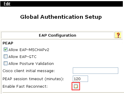
3. If the issue persists, contact Technical Support.
A client stays in authentication status
Symptom
A client stays in authentication status although all 802.1X settings and the username and password are correct.
Solution
To resolve the issue:
1. Disable the online user handshake feature by using the undo dot1x handshake enable command.
2. If the issue persists, contact Technical Support.
Local 802.1X authentication failure
Symptom
A client fails local 802.1X authentication.
Solution
To resolve the issue:
1. Use the debugging port-security command to examine whether port security is enabled globally. If it is not, use the port-security enable command to enable port security globally.
2. Verify that the port mode is set to bridge on the AC and that the AC has a valid PKI certificate.
3. Verify that the client is configured correctly.
4. If the issue persists, contact Technical Support.
A client cannot come online when remote MAC and PSK authentication is used
Symptom
A client cannot come online when remote MAC and PSK authentication is used even if a correct username and password are provided.
Solution
To resolve the issue:
1. Verify that the AC and the RADIUS server can reach each other.
2. Verify that port security is enabled globally.
3. Verify that the NAS IP and key configured on the AC are consistent with the configuration on the RADIUS server.
4. Verify that the format of the username to be sent to the RADIUS server is the same on the AC and the RADIUS server.
5. Verify that the other configurations on the server match the configurations on the AC.
6. If the issue persists, contact Technical Support.
A client cannot come online when local MAC and PSK authentication is used
Symptom
A client cannot come online when local MAC and PSK authentication is used even if the correct username and password are provided.
Solution
To resolve the issue:
1. Verify that the username configured for the local user is the same as the username configured for MAC authentication. If they are different, use the mac-authentication user-name-format command to change the username for MAC authentication.
2. Verify that the username configured for the local user does not contain upper-case letters.
[Sysname-luser-00-14-6c-72-29-5c]display this
#
local-user 00-14-6c-72-29-5c
password simple 00-14-6c-72-29-5c
authorization-attribute level 3
service-type lan-access
If uppercase letters exist, use the mac-authentication user-name-format command to specify a lower-case MAC authentication username and set the password to be the same as the username.
3. If the issue persists, contact Technical Support.
An AP fails to associate with an AC because auto AP is disabled
Symptom
The debugging messages indicate that the AC can receive AP packets, but fails to process them.
*Aug 11 15:26:16:766 2018 H3C CWS/7/RCV_PKT: Received discovery request from AP: IP address=180.10.1.67, MAC address=c4ca-d98e-c350,
serial ID=219801A0CLC11B000010.
*Aug 11 15:26:16:767 2018 H3C CWS/7/ERROR: Failed to process discovery request from AP with serial ID 219801A0CLC11B000010:
Solution
To resolve the issue:
1. Use the wlan auto-ap enable command to enable the auto AP feature.
By default, the auto AP feature is disabled.
2. If the issue persists, contact Technical Support.
Cloud-managed AP cannot connect to the cloud platform
Symptom
A cloud-managed AP cannot go online on the cloud platform after it is added to the platform.
Possible reasons
The following are the common causes for this type of issue:
· The SN code of the cloud-managed AP is not entered correctly when the AP is added to the cloud platform.
· The cloud-managed AP is not connected to the Internet.
· The cloud management configuration on the local Web interface of the AP is incorrect.
· The cloud-managed AP is already online on the AC.
Figure 9 Troubleshooting flowchart for cloud-managed AP connection failure to the cloud platform

Solution
To resolve the issue:
1. Verify that the SN of the cloud-managed AP is entered correctly on the cloud platform.
To obtain the SN of a cloud-managed AP, remove the panel cover of the AP. You can also read the SN of the AP from the nameplate on the rear of the AP.
2. Verify that the cloud platform has a license for cloud-managed APs.
Log in to the cloud platform, and navigate to the Network > Settings > Licenses page. Select the Installed Licenses tab and verify that the cloud platform has a license for cloud-managed APs.
|
|
NOTE: A newly registered cloud platform account has a trial cloud-managed AP license, which allows the platform to accommodate a maximum of 128 cloud-managed APs with up to 180 days per AP. After the trial period ends, the cloud-managed APs will automatically go offline. |
¡ If no such a license exists, purchase and install a formal license.
¡ If such a license exists, bind the license to the cloud-managed AP.
3. Verify that the cloud-managed AP has connected to the network.
Verify that the uplink device of the cloud-managed AP is connected to the network, and the cloud-managed AP can dynamically obtain an IP address from the uplink device and use the IP address to access the public network.
¡ If the cloud-managed AP cannot access the public network from the IP address, reconfigure the network.
¡ If the cloud-managed AP can access the public network from the IP address, go to the next step.
4. Verify that the cloud management configuration of the cloud-managed AP is correct.
Log in to the local Web interface of the cloud-managed AP, make sure the domain name of the cloud platform server is entered correctly. The correct domain name is cloudnet.h3c.com.
5. Verify that the CAPWAP tunnel of the cloud-managed AP is disconnected.
A cloud-managed AP can be managed by either an AC or a cloud platform, but not both simultaneously. When a cloud-managed AP already has a CAPWAP tunnel, it cannot go online on the cloud platform.
¡ If the cloud AP is currently online on an AC, you can use the undo wlan ap command in system view on the AC to delete the cloud-managed AP, or disconnect the physical link between the cloud-managed AP and the AC to disconnect the CAPWAP tunnel between the AP and the AC.
¡ If the cloud-managed AP is not online on the AC, proceed to the next step.
6. If the issue persists, collect the following information and contact Technical Support:
¡ Results of each step.
¡ The configuration file, log messages, and alarm messages.
WIPS countermeasures do not take effect
Symptom
WIPS countermeasures do not take effect.
Possible reasons
The following are the common causes for this type of issue:
· The area is outside the coverage range of the sensor AP's countermeasures.
· The configuration of the sensor AP is incorrect.
· The relevant configuration of the WIPS rules is incorrect.
· The sensor AP has not sent deauth frames to the client and AP.
Troubleshooting flowchart
Figure 10 Troubleshooting flowchart for failure of WIPS countermeasures to take effect

Solution
To resolve the issue:
1. Check the coverage range of the sensor AP.
The coverage range of the WIPS countermeasures is approximately 30 to 50 meters (98.43 to 164.04 in). Beyond this range, the countermeasure might be less effective or even ineffective. You can create a test SSID on the AP with countermeasures enabled, and then use a client to detect and measure the signal coverage area of the AP. The countermeasures take effect in the coverage area with signal strength greater than –75 dBm.
2. Verify that the configuration of the sensor AP is correct.
Identify whether wireless countermeasure have been enabled on the sensor AP, whether WIPS has been enabled on the specified radio interface, and whether the sensor AP has been added to the designated VSD.
# Create an AP named Sensor and enable WIPS on the AP
[AC] wlan ap Sensor model WA6320
[AC-wlan-ap-Sensor] serial-id 219801A28N819CE0002T
[AC-wlan-ap-Sensor] radio 1
[AC-wlan-ap-Sensor-radio-1] radio enable
[AC-wlan-ap-Sensor-radio-1] wips enable
[AC-wlan-ap-Sensor-radio-1] quit
# Add AP Sensor to virtual security zone vsd1.
[AC-wlan-ap-Sensor] wips virtual-security-domain vsd1
[AC-wlan-ap-Sensor] quit
3. Verify that the related configuration of the WIPS rules is correct.
Check the relevant configuration of the WIPS rules. Identify whether the classification rules are correctly defined, whether the classification rules are correctly assigned to the classification policies, whether the countermeasure policies are correctly defined, and whether the classification policies and countermeasure policies are correctly applied to the WIPS virtual security domain.
# Check the relevant configuration of the WIPS rules.
# Define a WIPS AP classification rule.
wips
ap-classification rule 1
ssid equal rwfz
# Define a WIPS classification policy.
classification policy class1
apply ap-classification rule 1 rogue-ap
# Define a WIPS countermeasure policy.
countermeasure policy 1
countermeasure rogue-ap
# Define a WIPS virtual security zone.
virtual-security-domain vsd1
apply classification policy class1
apply countermeasure policy 1
4. View countermeasures that WIPS has taken against devices.
On the AC, execute the display wips virtual-security-domain countermeasure record command to display information about countermeasures that WIPS has taken against devices.
<Sysname> display wips virtual-security-domain vsd1 countermeasure record
Total 3 times countermeasure, current 3 countermeasure record in virtual-security-domain vsd1
Reason: Att - attack; Ass - associated; Black - blacklist;
Class - classification; Manu - manual;
MAC address Type Reason Countermeasure AP Radio ID Time
1000-0000-00e3 AP Manu ap1 1 2016-05-03/09:32:01
1000-0000-00e4 AP Manu ap2 1 2016-05-03/09:32:11
2000-0000-f282 Client Black ap3 1 2016-05-03/09:31:56
5. View information of the devices against which WIPS has taken countermeasures.
On the AC, execute the display wips virtual-security-domain device command to display information about wireless devices detected in the VSD.
<Sysname> display wips virtual-security-domain vsd1 device verbose
Total 1 detected devices in virtual-security-domain vsd1
Client: 2000-0000-0000
Last reported associated AP: 1000-0000-0000
Classification: Uncate
Severity level: 0
Classify way: Auto
Dissociative status: No
Status: Active
Status duration: 00h 00m 02s
Vendor: Not found
Radio type: 802.11a
40mhz intolerance: No
Countermeasuring: No
Man in the middle: No
Total number of reported sensors: 1
Sensor 1:
Sensor ID: 2
Sensor name: 1
Radio ID: 1
RSSI: 50
Channel: 149
First reported time: 2014-06-03/14:52:56
Last reported time: 2014-06-03/14:52:56
Reported associated AP: 1000-0000-0000
6. Capture packets on the radio interface to identify whether the sensor AP has sent out deauth frames.
If the WIPS countermeasures have not taken effect, you can use wireless packet capture software to capture packets and identify whether the sensor AP has sent deauth frames to the clients and APs. If no wireless packet capture software or network card is available, go to the next step.
Figure 11 Capturing packets
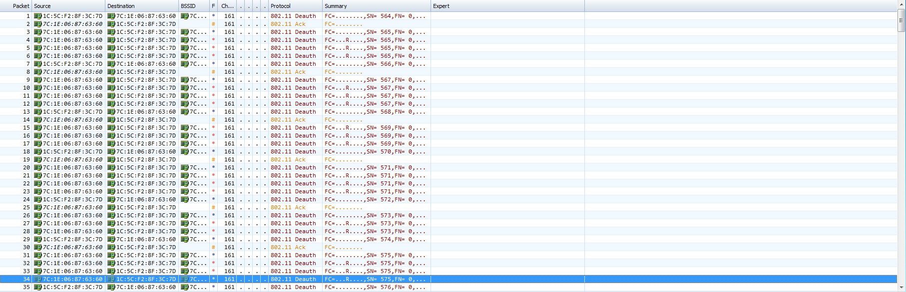
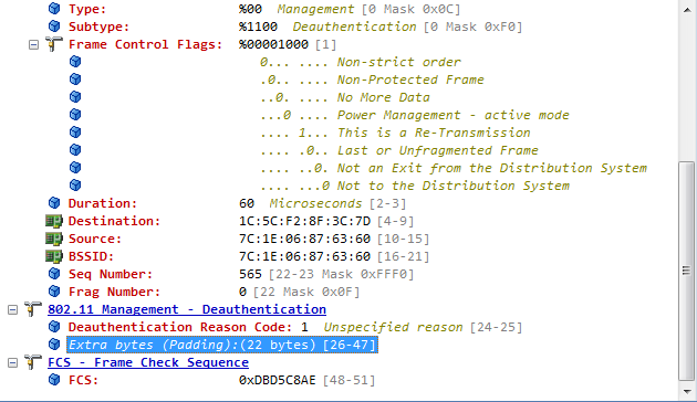
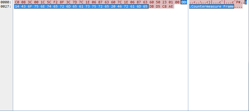
If "countermeasure frame" is displayed in the value of the Extra byte field, the frame is a deauth frame sent from the sensor AP and is a countermeasure frame.
7. Optimize operations.
In V7, no command is available for specifying the working mode for a sensor AP. If the AP radio does not bind to a wireless service template, the AP works only in the detection and countermeasure mode. If it binds to a wireless service template, the AP works in a mixed mode that provides detection and countermeasure and also access services. If channels are specified, the AP can also scan and countermeasure multiple channels. When the AP provides WIPS and access services simultaneously, access and detection durations are assigned, which weakens the detection and countermeasure functions. To achieve better intrusion prevention, configure the AP to provide the WIPS service separately.
Table 2 Optimizing operations
|
|
Access service duration (ms) |
Working channel scanning duration (ms) |
Polling channel scanning duration (ms) |
|
Common mode |
5000 |
100 |
100 |
|
Service first |
Determine if the access service is idle by using the scan idle-time idle-time command and then perform a scan. |
100 |
100 |
|
Probe and countermeasure only |
Directly perform periodic polling for all channels after detecting that no access service template is configured. |
0 |
100 |
8. Upgrade the software version.
Upgrade the AC to the latest version released on the official website. The new version has optimized and adjusted the WIPS features. For more information, see the resolve problems in the release notes for the new version.
9. If the issue persists, collect the following information and contact Technical Support:
¡ Version and model of the AC and AP.
¡ Command output of the debugging wips countermeasure command on the AC.
¡Diagnostic information on the AC.
Remote AP function not effective
Symptom
The remote AP function does not take effect. When the tunnel between AC and AP is disconnected, online endpoints go offline and new endpoints cannot access the network.
Possible reasons
The AC is configured as packet forwarder. As a result, the remote AP function does not take effect.
Analysis
Figure 12 shows the diagnostic process of this type of fault.
Figure 12 Problem analysis flowchart
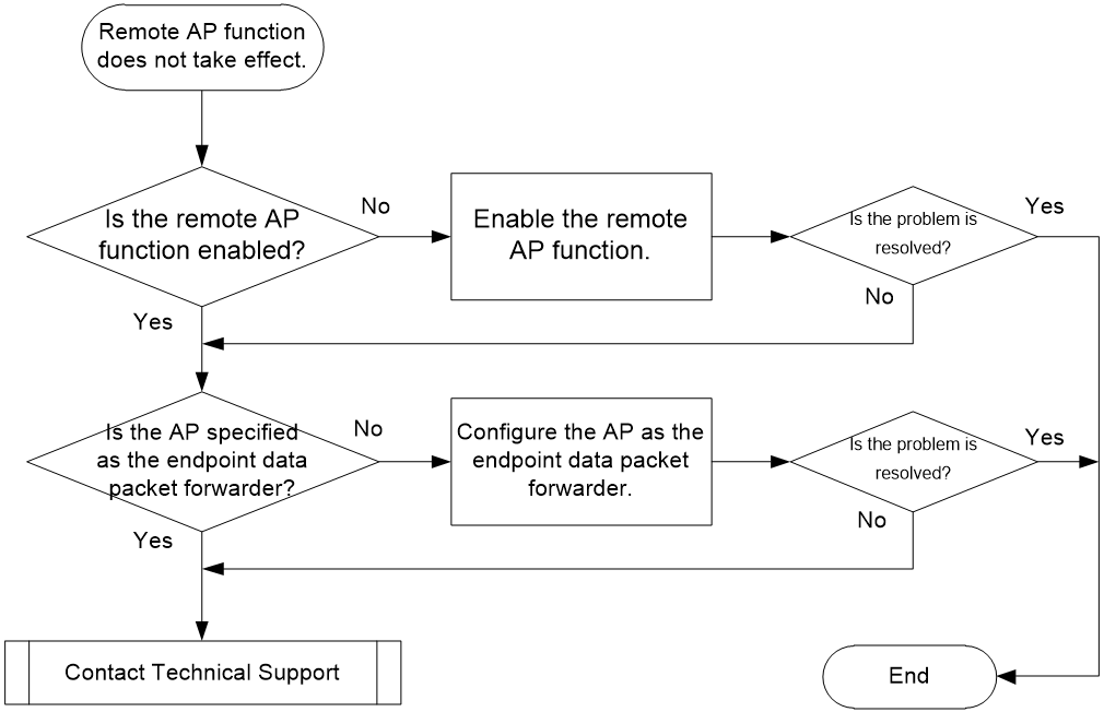
Solution
1. Verify that the remote AP function is enabled.
Check the configuration of AP or AP group and verify that the remote AP function is enabled on the AP. Enter AP or AP group view and execute the display this command to view the current configuration of the AP or AP group. Take the following operation as an example.
<AC> system-view
[AC] wlan ap ap1
[AC-wlan-ap-ap1] display this
#
wlan ap ap1 model WA5320
vlan 1
bonjour enable
hybrid-remote-ap enable
rfid-tracking aeroscout enable
rfid-tracking cupid enable
radio 1
type dot11a
radio enable
radio 2
gigabitethernet 1
gigabitethernet 2
#
¡If the remote AP function is not enabled in the AP or AP group configuration, you need to execute the hybrid-remote-ap enable command in the AP or AP group view to enable the function.
¡If the remote AP function is already enabled in the AP or AP group configuration, proceed to step 2.
2. Identify the packet forwarder.
Check the template configuration for the wireless service to which the endpoint is connected. The remote AP function takes effect only when endpoint data packets. To view the current configuration, execute the display this command in wireless service template view. Take the following operation as an example.
<AC> system-view
[AC] wlan service-template 1
[AC-wlan-st-1]display this
#
wlan service-template 1
ssid service
client forwarding-location ap
akm mode psk
preshared-key pass-phrase cipher $c$3$X2Rlxl49vpJ158WfBfCMdjt0NpHVdUHApNcS
cipher-suite ccmp
security-ie rsn
ip verify source
service-template enable
#
¡If the AC is specified as the endpoint data packet forwarder, you can use the client forwarding-location ap command to enable the AP to forward data packets in wireless service template view.
¡If the AP is specified as the endpoint data packet forwarder, proceed to step 3.
3. If the issue persists, collect the following information, and contact Technical Support:
¡The execution result of the previous steps.
¡The configuration file, log information, and alarm information.
Access failure of new endpoint after the remote AP function is enabled
Symptom
When the tunnel between AC and AP is disconnected and the remote AP function takes effect, the services of the existing endpoint are not affected, but the new endpoint fails to access the network.
Possible reasons
The common reasons of this issue include the following:
· The AP is not specified as the authenticator or enabled with association. As a result, new endpoints cannot complete the association or authentication process.
· During remote authentication, relevant configurations are not deployed to the AP, which prevents new endpoints from accessing the network.
· During local MAC authentication, relevant configurations are not deployed to the AP, which prevents new endpoints from accessing the network.
Figure 13 Problem analysis flowchart
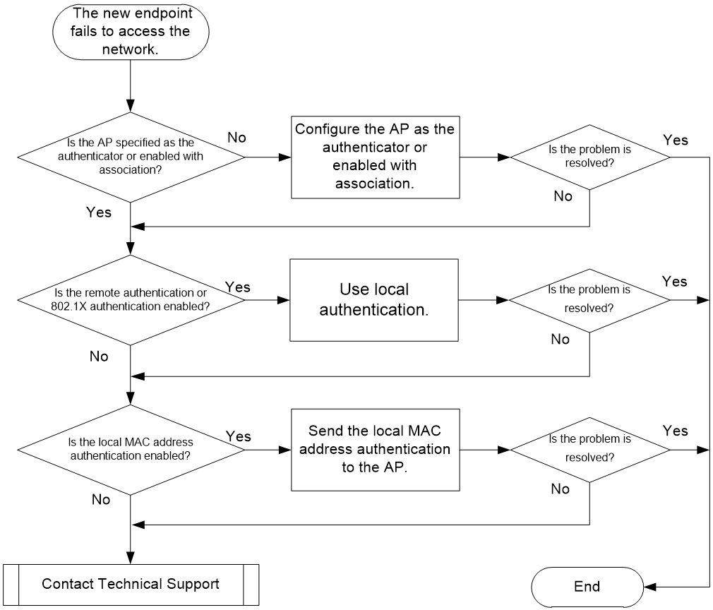
Solution
1. View association and authentication configuration
View configuration of the wireless service template to which the endpoint is connected. Execute the display this command in wireless service template view to check the current configuration. Take the following operation as an example.
<AC> system-view
[AC] wlan service-template 1
[AC-wlan-st-1]display this
#
wlan service-template 1
ssid service
client forwarding-location ap
client association-location ap
client-security authentication-location ap
akm mode psk
preshared-key pass-phrase cipher $c$3$X2Rlxl49vpJ158WfBfCMdjt0NpHVdUHApNcS
cipher-suite ccmp
security-ie rsn
ip verify source
service-template enable
#
¡If endpoint association or user access authentication are enabled on the AC, enable endpoint association at the AP by using the client association-location ap command in wireless service template view, and enable user access authentication on the AP by using the client-security authentication-location ap command.
¡If the AP is enable with endpoint association and specified as user access authenticator, proceed to step 2.
2. View remote authentication configuration.
|
|
IMPORTANT: In a remote AP scenario, newly connected endpoints can directly access the network without portal authentication. |
Remote authentication has no impact on existing endpoint services. The newly connected endpoints must meet the following conditions in order to access the network:
¡ Network connectivity is available between the AP and the remote authentication server.
¡ All remote authentication configurations are deployed to the AP through a MAP file.
As a best practice, do not use remote authentication in remote AP scenarios, because remote authentication greatly consumes AP resource and affects performance.
¡If remote authentication is enabled, you can modify the configuration and use local authentication.
¡If remote authentication is disabled, proceed to step 3.
3. View local authentication configuration.
|
|
IMPORTANT: In a remote AP scenario, portal authentication is invalid. New endpoints can directly access the network without portal authentication. |
If local MAC address authentication is enabled, in order for the new endpoints to access the network correctly, you must send domain name and local user information to the AP through a MAP file. The following takes the configuration deployed through a MAP file as an example.
# Edit the apcfg.txt configuration file.
system-view
Interface GigabitEthernet 1/0/1
port link-type trunk
port trunk permit vlan 44
#
domain mac1
Authorization-attribute idle-cut 15 1024
Authentication lan-access local
#
local-user 3cf0114e7811 class network
password simple 3cf0114e7811
service-type lan-access
# Upload configuration file apcfg.txt to the AC. (Details not shown.)
# Deploy configuration file apcfg.txt on the AC to the AP.
[AC-wlan-ap-ap1] map-configuration apcfg.txt
[AC-wlan-ap-ap1] quit
¡If local authentication is not configured, proceed to step 4.
4. If the issue persists, collect the following information, and contact Technical Support.
¡The execution result of the previous steps.
¡The configuration file, log information, and alarm information.
ACL deployment failure in 802.1X authentication
Symptom
ACL deployment fails in 802.1X authentication.
Possible reasons
The common reasons of this issue include the following:
· The configuration of 802.1X authentication is incorrect.
· The corresponding ACL is not configured on the AC or the ACL configuration is incorrect.
· The route between the AC and the server is unreachable.
· The ACL number delivered by the server is incorrect.
· In local forwarding mode, no corresponding ACL configuration is added to the MAP file of the AP.
· The server does not deploy the ACL attribute.
Analysis
Figure 14 shows the diagnostic process of this type of fault.
Figure 14 Problem analysis flowchart

Solution
1. Check the 802.1X authentication configuration.
Verify that the configurations on the AC are correct based on 802.1X authentication configuration examples. For example, verify that the RADIUS scheme, domain, and 802.1X authentication settings are correctly configured for the wireless service template.
2. Check the ACL configuration on the AC.
The authentication server only issues the ACL number. If the corresponding ACL is not configured on the AC, the authorization does not take effect. Verify that the corresponding ACL is correctly configured.
Use the display acl command to view the ACL configuration on the AC.
[AC] display acl 3001
Advanced IPv4 ACL 3001, 1 rule,
ACL's step is 5
rule 1 deny ip destination 192.168.137.6 0
3. Verify that the communication between the AC and the server is normal.
When performing 802.1X authentication, the AC and the server must directly exchange RADIUS protocol packets, and communicate by using the IP address specified in the radius nas-ip command. Make sure the IP address specified in the radius nas-ip command on the AC can be routed to the server.
You can use the ping –a source-IP-address destination-IP-address command to verify that the communication between the AC and the server is normal.
<AC> ping –a
192.168.137.6 1.1.1.3
Ping 1.1.1.3 (1.1.1.3) from 192.168.137.6: 56 data bytes, press CTRL_C to break
56 bytes from 1.1.1.3: icmp_seq=0 ttl=255 time=0.945 ms
56 bytes from 1.1.1.3: icmp_seq=1 ttl=255 time=0.556 ms
56 bytes from 1.1.1.3: icmp_seq=2 ttl=255 time=0.530 ms
56 bytes from 1.1.1.3: icmp_seq=3 ttl=255 time=0.550 ms
56 bytes from 1.1.1.3: icmp_seq=4 ttl=255 time=0.538 ms
4. Verify that the ACL number issued by the server on the server side is correct.
When performing 802.1X authentication, the server carries the ACL number that needs to be deployed to the endpoint in a RADIUS packet with the Code field set to 2. Verify that the ACL number received by the endpoint from the server is correct.
Use the display wlan client mac-address mac-address verbose command to view the ACL number deployed by the server on the endpoint side.
<AC> display wlan client mac-address 0015-00ba-0428 verbose
Total number of clients: 1
MAC address : 0015-00ba-0428
IPv4 address : 138.200.0.1
IPv6 address : N/A
Username
: wjh1x
…
AKM mode : 802.1X
Cipher suite : CCMP
User authentication mode : 802.1X
Authorization ACL ID : 3001
If the ACL deployment fails, the Authorization ACL ID field will be displayed as N/A. If the ACL deployment is successful, the Authorization ACL ID field will display the specific ACL number.
5. Check the configuration of the MAP file for local forwarding.
Check the forwarding method of the wireless service. If it is local forwarding, you need to add the corresponding ACL configuration to the MAP file of the corresponding AP.
You can use the more apcfg.txt command to view the configuration of the MAP file.
<AC> more apcfg.txt
system-view
vlan 200
quit
interface GigabitEthernet 1/0/1
port link-type trunk
port trunk permit vlan 200
6. Verify that the server has deployed ACL attributes.
According to the RADIUS protocol specification, the server carries the ACL authorization attribute in a RADIUS packet with the Code field set to 2. You can capture packets to verify whether the RADIUS packet contains the attribute value pairs field, and whether the deployed value matches the corresponding ACL value.
Figure 15 Verify that the server has deployed the ACL attribute
7. Contact Technical Support.
If the issue persists, collect diagnostic and packet capture information from the AC, and contact Technical Support.
Wireless endpoint failure to obtain an IP address in centralized forwarding mode
Symptom
In an AC + fit AP network, an wireless endpoint in centralized forwarding mode can connect to the wireless network, but cannot obtain an IP address, which prevents it from accessing the Internet.
The troubleshooting procedures vary in centralized and local forwarding modes. Before you start troubleshooting, first identify the forwarding mode. Execute the display wlan service-template verbose command to identify the forwarding mode of the wireless service template in any view of the AC. The Forwarder field displayed as AC indicates the centralized forwarding mode.
<AC> display wlan service-template 1 verbose
Service template name : 1
Description : Not configured
SSID : 123
…
Forwarder : AC
Possible reasons
The common reasons of this issue include the following:
· The VLAN configuration of the device is incorrect, which prevents the endpoint from obtaining an IP address.
· The interface configuration of the device is incorrect, which prevents the endpoint from obtaining an IP address.
· The link between the wireless endpoint and the DHCP server is not working correctly.
· When you configure VLAN-based endpoint isolation, the actual MAC address of the gateway might not match the configured MAC address. This will block DHCP and ARP broadcast packets, which prevents the endpoint from obtaining an IP address.
· A problem occurs in the DHCP message exchange process between the wireless endpoint and DHCP server, which prevents the endpoint from obtaining an IP address.
Analysis
Figure 16 shows the diagnostic process of this type of fault.
Figure 16 Problem analysis flowchart
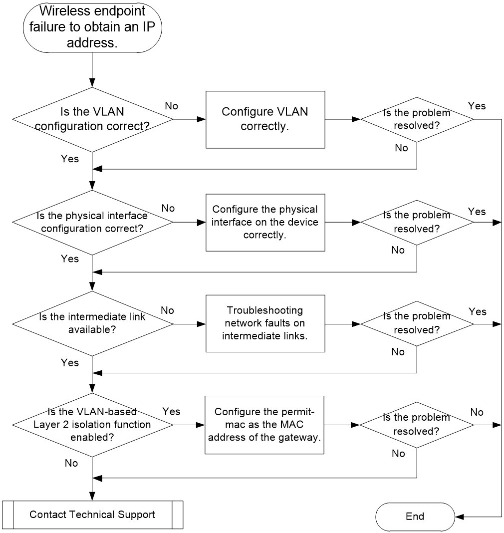
Solution
1. Check the VLAN configuration in the network.
In centralized forwarding mode, the client's data traffic is transmitted through the CAPWAP tunnel by the AP to the AC, and the AC forwards the data packets. Typically, the management VLAN for AP onboarding and the service VLAN for wireless endpoint access are available. Data packets are sent to the AC through the management VLAN and then forwarded to the service VLAN. For the endpoint to obtain an IP address, you need to allow the service VLAN to pass through the link where the AC forwards service packets.
|
|
IMPORTANT: A service VLAN can be configured in multiple ways. Authentication and authorization VLAN has the highest priority. The VLAN bound to radio interface has lower priority. The VLAN specified in the service template has the lowest priority. |
As shown in Figure 17, the core switch serves as the gateway. The AC is attached to the core switch, and the AP is connected to the access switch. You need to permit VLAN 200 on the AC-Switch1 link where the AP forwards wireless service packets.
Figure 17 VLAN configuration in centralized forwarding mode
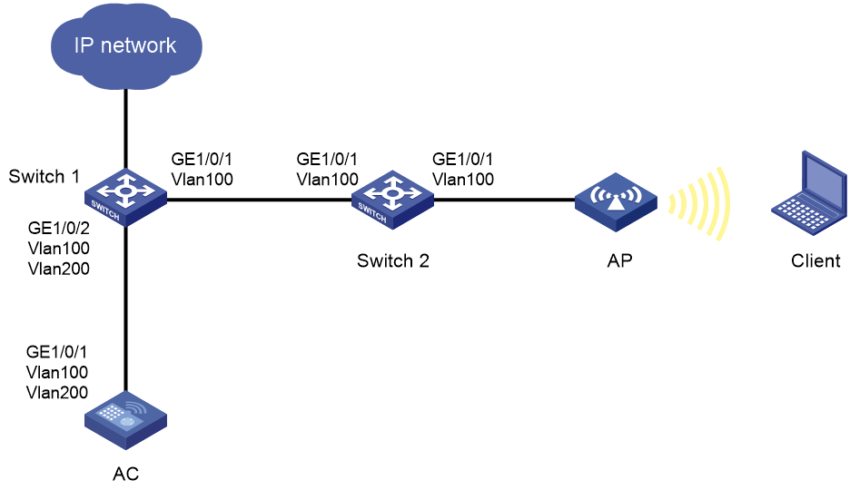
Execute the display current-configuration command in any view to view configuration of all VLANs on the device.
<Sysname> display current-configuration
#
vlan 100
#
vlan 200
#
…
#
interface Vlan-interface100
ip address 192.1.1.1 255.255.0.0
#
interface Vlan-interface200
ip address 192.2.1.1 255.255.255.0
#
interface GigabitEthernet1/0/1
port link-type trunk
undo port trunk permit vlan 1
port trunk permit vlan 100 200
¡If the VLAN configuration of the device is incorrect, see the previous sections to edit the configuration.
¡If the VLAN configuration of the device is correct, proceed to step 2.
2. Check the physical interface configuration in the network.
Incorrect physical interface configuration might cause failure to allow the VLAN to pass through. As shown in Figure 17, specify the trunk mode for physical interfaces GE1/0/1 and GE1/0/2 attached to the link between the AC and the gateway Switch1, and allow service VLAN 200 to pass through.
Execute the display current-configuration command to view configuration of all interfaces on the device in any view.
¡If the interface configuration is incorrect, edit the configuration according to the previous sections or the actual situation.
¡If the interface is configured correctly, proceed to step 3.
3. Verify that the intermediate link is available.
If the intermediate link is not available, the endpoint cannot obtain an IP address through DHCP. The following methods can be used to determine whether the intermediate link is available:
a. In any view of the DHCP server (typically the gateway device or AC), execute the display mac-address command to verify that the MAC address of the wireless endpoint and the corresponding VLAN are correctly configured in the MAC address table. If the MAC address of the wireless endpoint is learned correctly, the Layer 2 network is available. If not, the Layer 2 network is not available.
<Sysname> display mac-address
MAC Address VLAN ID State Port/Nickname Aging
0008-2246-da06 200 Client WLAN-BSS1/0/527 N
5098-b853-5201 790 Learned BAGG1 Y
b. Manually configure a static IP address for the wireless endpoint in the same network segment as the gateway, and then ping the gateway. If the ping is successful, the intermediate link is available.
¡If the intermediate link is not available, troubleshoot the intermediate link network fault.
¡If the intermediate link is available, proceed to step 4.
4. View the configuration of the VLAN-based Layer 2 isolation function.
In order to reduce the number of broadcast packets in the wireless LAN of the backbone network, the wireless network might be configured with VLAN-based Layer 2 isolation. Typically, configure the permit-mac as the MAC address of the gateway. If the MAC address of the gateway changes due to network adjustments and the configuration of the layer 2 isolation is not updated, broadcast packets might be blocked. As a result, the wireless endpoint cannot obtain an IP address through DHCP. The following shows a configuration example.
# Enable endpoint isolation for VLAN 200, allowing access to the device with MAC address 00bb-ccdd-eeff (typically the MAC address of the gateway) and prohibiting wired endpoints (excluding MAC addresses allowed by the permit-mac setting) from sending broadcast or multicast packets to wireless endpoints.
<AC> system-view
[AC] user-isolation vlan 200 enable
[AC] user-isolation vlan 200 permit-mac 00bb-ccdd-eeff
[AC] undo user-isolation permit-broadcast
Execute the display user-isolation statistics command to view the configuration of the VLAN-based Layer 2 isolation function in any view. The following is an example.
<Sysname> display user-isolation statistics
Number of VLANs enabled with user isolation: 2
Number of VLANs disabled with user isolation: 1
VLAN Status Drops Permit-Unicast Permitted MACs Permit IPv4|I
Pv6 Acl
4 Enabled 0 Y N/A 3001|3002
200 Enabled 0 Y 00bb-ccdd-eeff N/A|N/A
5 Enabled 0 Y N/A N/A|N/A
¡If the VLAN-based Layer 2 isolation function is configured incorrectly, see the example to modify the configuration.
¡If the VLAN-based Layer 2 isolation function is configured correctly or not configured, proceed to step 5.
5. If the issue persists, collect the following information, and contact Technical Support:
¡Capture packets on the uplink interface of the AP to determine the DHCP message exchange process.
When the DHCP message exchange between devices is incomplete, the endpoint cannot obtain an IP address. As shown in the figure, the complete DHCP message exchange process must contain four message types:
Table 3 Complete DHCP message exchange process
|
Type of DHCP messages |
Description |
|
DHCP Discover |
The DHCP client broadcasts a DHCP-DISCOVER message within the local network to locate a DHCP server. All DHCP servers that receive the DHCP-DISCOVER message send response messages. Based on these response messages, the DHCP client can locate a DHCP server in the network. |
|
DHCP Offer |
After receiving the DHCP-DISCOVER message, each DHCP server offers configuration parameters (such as an IP address selected from the configured address pool, lease, gateway, DNS server) in a DHCP-OFFER message to the client. |
|
DHCP Request |
If the client receives multiple offers, it accepts the first received offer, and broadcasts it in a DHCP-REQUEST message to formally request the IP address. After the DHCP client successfully obtains an IP address, it also renews the lease period through a DHCP-REQUEST message. |
|
DHCP ACK |
After receiving the DHCP-REQUEST message, the DHCP server searches for the lease record based on the user MAC address carried in the request message. If a lease record is found, the server returns a DHCP-ACK message to confirm that the IP address has been allocated to the client. |
Figure 18 Packets captured in the complete DHCP message exchange process

¡Use the debugging dhcp server command on the DHCP server to collect information and verify that the client has sent a DHCP request.
Debugging information for receiving the DHCP-DISCOVERY message sent by the client is as follows:
*Oct 14 11:43:09:422 2020 AC DHCPS/7/PACKET:
From 0.0.0.0 port 68, interface M-GigabitEthernet0/0/0
Message type: REQUEST (1)
Hardware type: 1, Hardware address length: 6
Hops: 0, Transaction ID: 650682081 //Make sure the same TID is used in a DHCP message exchange process
Seconds: 0, Broadcast flag: 1
Client IP address: 0.0.0.0 Your IP address: 0.0.0.0
Server IP address: 0.0.0.0 Relay agent IP address: 0.0.0.0
Client hardware address: 782c-2962-b098
Server host name: not configured
Boot file name: not configured
DHCP message type: DHCPDISCOVER (1) //DHCP message type
¡The execution result of the previous steps.
¡The configuration file, log information, and alarm information.
A wireless client cannot obtain an IP in local forwarding mode
Symptom
A wireless client can connect to the Wi-Fi network in an AC+fit AP network where local forwarding mode is used, but it cannot obtain an IP address, resulting in no Internet access.
The troubleshooting procedure is different for centralized forwarding and local forwarding. First, identify the current forwarding mode. In any view on the AC, execute the display wlan service-template verbose command to view the forwarding mode of the wireless service template. If the value of the Forwarder field is AP, local forwarding mode is used.
<AC> display wlan service-template 1 verbose
Service template name : 1
Description : Not configured
SSID : 123
…
Forwarder : AP
Possible reasons
The following are the common causes for this type of issue:
· The VLAN configuration of the devices is incorrect.
· The interface configuration of the devices is incorrect.
· The wireless client cannot connect to the DHCP server.
· DHCP message exchange between the wireless client and DHCP server is abnormal.
· The MAC address actually issued to the fit AP in VLAN-based user isolation configuration is inconsistent with the configured MAC address. As a result, DHCP and ARP broadcast packets are blocked, causing IP address obtaining failure of the client.
· In the roaming scenario, not all service VLANs are permitted on the AP uplink.
Figure 19 Troubleshooting flowchart for failure of a wireless client to obtain an IP address in local forwarding mode
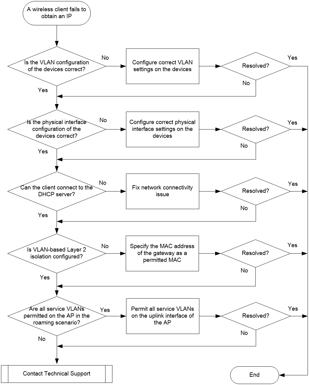
Solution
To resolve the issue:
1. Check the VLAN configuration.
In local forwarding mode, a wireless client and AC exchange control packets via a CAPWAP tunnel and the AP forwards data packets. Typically, the management VLAN where the AP comes online is different from the service VLAN to which the wireless client access. The service VLAN must be permitted on the AP link that forwards service packets. If not permitted, the client cannot obtain an IP address.
|
|
NOTE: Service VLANs can be configured in multiple ways. The priority of service VLANs, in descending order, is as follows: authentication and authorization VLAN, radio interface bound VLAN > service template specified VLAN. |
As shown in Figure 20, the core switch acts as the gateway, the AC is attached to the core switch, and the AP is connected to the access switch. VLAN 200 is permitted on the wireless packet-forwarding link Switch 1–Switch 2–AP.
Figure 20 AC+fit AP network with local forwarding

To check the VLAN configuration, execute the display current-configuration command in any view on the device.
<Sysname> display current-configuration
#
vlan 100
#
…
#
interface Vlan-interface100
ip address 192.1.1.1 255.255.0.0
#
interface GigabitEthernet1/0/1
port link-type trunk
port trunk permit vlan 100
¡If the VLAN configuration of the device is incorrect, modify the configuration by referring to the preceding configuration example or according to the actual conditions.
¡If the VLAN configuration of the device is incorrect, proceed to the next step.
2. Check the physical interface configuration
Incorrect physical interface configuration might cause failure to permit VLAN traffic. As shown in Figure 20, the correct physical interface configuration is as follows:
¡ In local forwarding mode, add the physical interface of the AP that connects the upstream device to the VLAN where the client comes online. You can issue the edited MAP file to AP from the AC or through remote configuration. The MAP file method is used in this example.
In this example, the wireless client comes online in VLAN 200. Add interface GigabitEthernet 1/0/1 that connects the AP to the switch to VLAN 200. Configure the MAP file as follows:
|
|
NOTE: The apcfg.txt is a text file. Add the command lines based on their configuration sequence to the file and upload it to the AC. Once the AC is associated with the AP, you can use the map-configuration command to issue the configuration to the AP and completes the AP configuration. |
# apcfg.txt configuration file:
system-view
vlan 200
quit
interface GigabitEthernet 1/0/1
port link-type trunk
port trunk permit vlan 200
¡ Configure the downlink interface of gateway Switch 1 and the uplink and downlink physical interfaces of access switch Switch 2 as trunk ports and permit traffic from VLAN 200. Set the PVID of interface GE1/0/2 that connects Switch 2 and AP as 100.
To check the configuration of an intermediate devices, execute the display current-configuration command in any view. This command displays all VLAN and interface configuration on the intermediate device.
<Sysname> display current-configuration
#
vlan 100
#
vlan 200
#
interface Vlan-interface100
ip address 192.1.1.2 255.255.0.0
#
interface Vlan-interface200
ip address 192.2.1.1 255.255.255.0
#
interface GigabitEthernet1/0/1
port link-mode bridge
port link-type trunk
port trunk permit vlan 1 100
#
interface GigabitEthernet1/0/2
port link-mode bridge
port link-type trunk
undo port trunk permit vlan 1
port trunk permit vlan 100 200
port trunk pvid vlan 100
#
- If the interface configuration of the device is incorrect, modify the configuration by referring to the preceding example or according to the actual conditions.
- If the interface configuration of the device is correct, proceed to the next step.
3. Verify that the client has network connectivity to the DHCP server.
If the client does not have network connectivity to the DHCP server, the client cannot obtain an IP address through DHCP. You can use either of the following ways to check the network connectivity:
a. Execute the display mac-address command in any view of the DHCP server (typically, the gateway device but could also be the AC) to check if the MAC address of the wireless client exists in the MAC address table and if the VLAN ID is correct. If the MAC address of the wireless client exists in the table, the client and the DHCP are reachable to each other at Layer 2.
<Sysname> display mac-address
MAC Address VLAN ID State Port/Nickname Aging
0008-2246-da06 200 Client WLAN-BSS1/0/527 N
5098-b853-5201 790 Learned BAGG1 Y
b. Configure a static IP address in the same network segment as the gateway for the wireless client, and then ping the gateway. If the ping operation is successful, the client and DHCP have network connectivity.
¡ If the client and DHCP do not have network connectivity, troubleshoot the links.
¡ If the client and DHCP have network connectivity, proceed to the next step.
4. Check the VLAN-based Layer 2 isolation configuration issued to the fit AP.
In order to reduce the number of broadcast messages from the backbone network to the wireless LAN, the wireless network might be configured with VLAN-based Layer 2 isolation. Typically, the MAC address of the gateway is set as a permitted MAC. If the Layer 2 isolation configuration is not modified after the MAC address of the gateway is changed, broadcast packets might be blocked. As a result, the wireless client cannot obtain an IP address through DHCP. In local forwarding mode, the configuration needs to be issued to the AP. The typical configurations as follows:
# apcfg.txt configuration file:
system-view
system-view
user-isolation vlan 200 permit-mac 000f-e212-7788
user-isolation vlan 200 enable
¡If VLAN-based layer 2 isolation is configured incorrectly, modify the configuration by referring to the preceding example.
¡If VLAN-based Layer 2 isolation is configured correctly, proceed to the next step.
5. Check if the AP permits traffic from all service VLANs in the roaming scenario.
In the roaming scenario where the wireless clients come online from multiple service VLANs, each AP in the wireless network needs to permit traffic from all service VLANs on its uplink interface. Otherwise, a client might not be able to connect to the wireless network when it roams. As shown in Figure 21, you must permit traffic from VLAN100, VLAN200, and VLAN300 on the GE1/0/1 interfaces of AP1, AP2, and AP3. For information how to issue the configuration to the AP with a MAP file, see step 2.
Figure 21 Multiple service VLANs existing in the roaming scenario
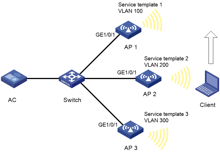
¡If multiple service VLANs exist in the roaming scenario but the AP uplink interfaces do not permit traffic from all these VLANs, modify the configuration by referring to the preceding example or according to actual conditions.
¡If the AP uplink interfaces permit traffic from all the service VLANs, proceed to the next step.
6. If the issue persists, collect the following information and contact Technical Support:
¡Capture DHCP interaction messages on the uplink interface of the AP.
A wireless client cannot obtain an IP address if the DHCP interaction is incomplete. The complete DHCP interaction process requires four message exchanges.
Table 4 DHCP interaction process
|
DHCP packet Type |
Description |
|
DHCP Discover |
When a client connects to a network, it sends a DHCP Discover message in broadcast mode to search for available DHCP servers within the network. |
|
DHCP Offer |
All the DHCP servers in the network that receive the DHCP Discover message respond with a DHCP Offer message. This message includes an available IP address from the server's address pool, along with other network configuration information such as subnet mask, default gateway, and DNS server address. |
|
DHCP Request |
The client device typically selects the first DHCP Offer it receives and sends a DHCP Request message back to the chosen DHCP server. This message is a formal request for the offered IP address and network configuration information. |
|
DHCP ACK |
Upon receiving the DHCP Request message, the DHCP server reserves the IP address for the client device and sends a DHCP ACK message to confirm the allocation. This message also contains the lease duration and any additional network configuration information. |
Figure 22 Capturing the DHCP interaction messages
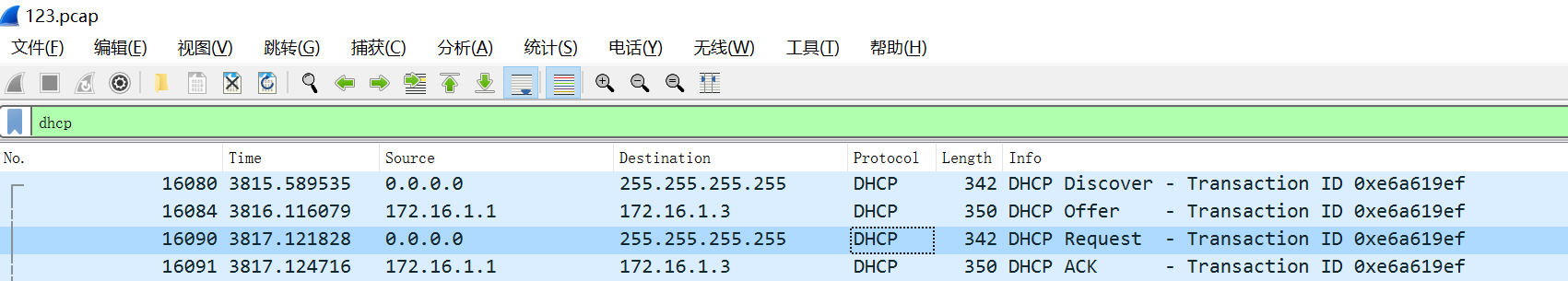
¡The output of the debugging dhcp server command on the DHCP server. From this command output, you can determine whether the client has sent a DHCP Discover message.
The debug information will be as follows if the DHCP server has received the DHCP Discover message from the client:
*Oct 14 11:43:09:422 2020 AC DHCPS/7/PACKET:
From 0.0.0.0 port 68, interface M-GigabitEthernet0/0/0
Message type: REQUEST (1)
Hardware type: 1, Hardware address length: 6
Hops: 0, Transaction ID: 650682081 //Check if the TID is the same for the same DHCP interaction process.
Seconds: 0, Broadcast flag: 1
Client IP address: 0.0.0.0 Your IP address: 0.0.0.0
Server IP address: 0.0.0.0 Relay agent IP address: 0.0.0.0
Client hardware address: 782c-2962-b098
Server host name: not configured
Boot file name: not configured
DHCP message type: DHCPDISCOVER (1) // DHCP packet type
¡Results of each step.
¡The configuration file, log messages, and alarm messages.
Troubleshooting non-device issues
This section provides troubleshooting information for common non-device issues.
A fit AP fails to obtain an IP address
Symptom
A fit AP cannot but a client can obtain an IP address from the DHCP server and use the network resources.
Solution
To resolve the issue:
1. Identify whether the uplink network is reachable:
a. Verify that the fit AP can communicate with the AC and connect to the AC by using a static IP address.
b. Replace the DHCP server with a PC and replace the fit AP with another PC. Configure static IP addresses for the two PCs.
c. Clear the ARP entries on the two PCs. PC 1 cannot ping PC 2 but PC 2 can ping PC 1 successfully. It indicates that the uplink network is reachable.
2. Capture packets to locate and resolve downlink network issues.
3. If the issue persists, contact Technical Support.
A client associates with a weak-signal AP rather than a strong-signal and closer AP
Symptom
A client associates with an AP with weak signals rather than an AP with stronger signals and shorter distance.
Solution
To resolve the issue:
1. Verify that the APs are evenly distributed and the clients are evenly associated with the APs.
2. If client association failures occur, disable load balancing.
As a best practice, use session-based instead of traffic-based load balancing, especially when the maximum number of associated clients for an AP is restricted by encryption and security configuration.
3. If the issue persists, contact Technical Support.
WMM cannot fragment packets
Symptom
The maximum fragment size for CAPWAP control or data packets is set to 256 for an AP. After a client is associated with the AP, execute a ping command with –s 500 specified to ping the client from the AP. The output shows that the packets are not fragmented.
Solution
To resolve the issue:
1. Use the wmm disable command to disable WMM.
2. If the issue persists, contact Technical Support.
Failure to configure wireless connection when WirelessZeroConfigure has been enabled
Symptom
After you enable the wireless NIC on a client and refresh the wireless service list, the system displays a message indicating wireless connection configuration failure. However, WirelessZeroConfigure has been enabled.
Solution
To resolve the issue:
1. Uninstall or shut down the client management software on the wireless NIC and other related client management software such as iNode.
2. Enable WirelessZeroConfigure.
3. If the issue persists, contact Technical Support.
Failure to log in to the AC from the Web interface
Symptom
The client cannot log in to the AC in the Web interface but it can ping the AC and telnet to the AC.
Solution
To resolve the issue:
1. Disable the Windows firewall.
2. Telnet to the AC.
3. Examine the AC configuration and use the ip http enable and ip https enable commands to enable the HTTP and HTTPS services.
4. If the issue persists, contact Technical Support.
Failure to modify auto-AP configuration
Symptom
The configuration of an auto AP cannot be modified.
Solution
To resolve the issue:
1. Use the wlan auto-ap persistent command to convert the auto AP to a manual AP.
The system does not support modifying auto APs.
2. If the issue persists, contact Technical Support.
Failure to upgrade AP software by downloading images from the preconfigured location
Symptom
Software upgrade fails for an AP when the AP upgrades its software from one Comware 7 version to another Comware 7 version by downloading the upgrade images from the preconfigured location.
Possible reasons
The common reasons of this issue include the following:
· The AP goes offline when it is downloading the images.
· The memory on the AP is insufficient.
· The images to be downloaded do not exist.
· Failed to retransmit the AP software images.
· The response to the image download request times out.
Analysis
Figure 23 shows the diagnostic process of this type of fault.
Figure 23 Problem analysis flowchart
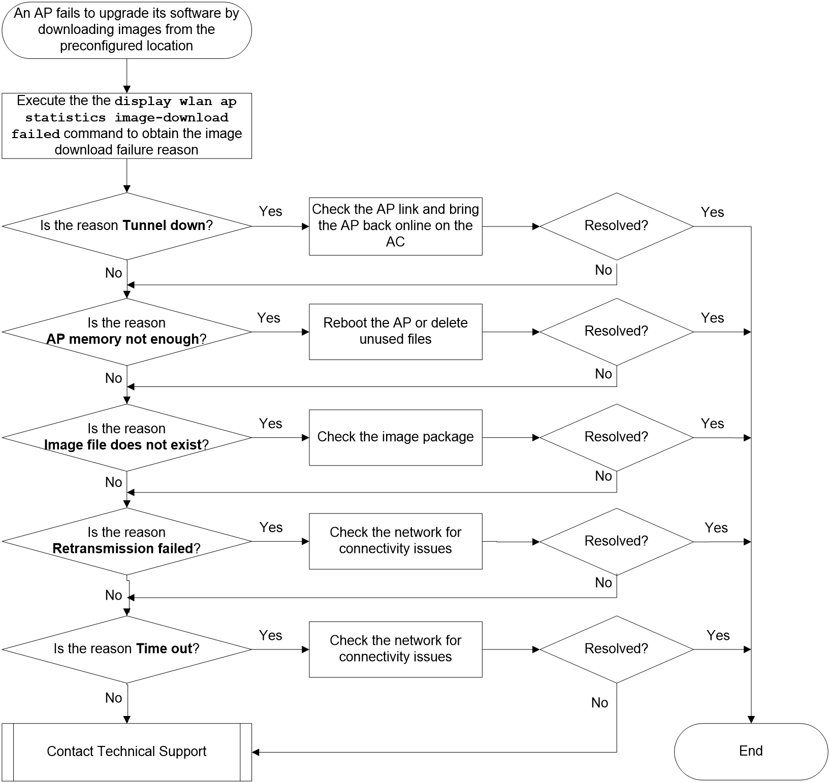
Solution
|
|
IMPORTANT: You can use the display wlan ap statistics image-download command to display the following AP image downloading information: · Percentage of APs that have completed image downloading. · Time that has been consumed for image downloading. · Total number of APs that need to be upgraded. · Number of APs that have successfully downloaded images. · Number of APs that are downloading images. · Number of APs that have failed to download images. |
1. Execute the display wlan ap statistics image-download failed command to obtain the image download failure reason.
[Sysname] display wlan ap statistics image-download failed
AP name Failure reason
ap1 Tunnel down
ap2 AP memory not enough
ap3 Image file does not exist
¡ If the failure reason is Tunnel down, the AP has gone offline. In this case, check the AP link, bring the AP back online on the AC, and reconfigure the AC to push the images to the AP.
¡ If the failure reason is AP memory not enough, reboot the AP or delete unused files. After the AP is back online, download the images to the AP.
¡ If the failure reason is Image file does not exist, verify that the image package exists and no exceptions have occurred on the image package. For more information, see "Failure to automatically upgrade AP software through the AC."
¡ If the failure reason is Retransmission failed, retransmission fails for the image package. In this case, check the network conditions to identify whether the network has high latency or packet loss issues.
¡ If the failure reason is Time out, the response to the image download request times out. In this case, check the network conditions to identify whether the network has high latency or packet loss issues.
2. If the upgrade failure issue persists, collect the following information on the AC and AP, and contact Technical Support:
<Sysname> debugging wlan capwap error all
<Sysname> terminal debugging
The current terminal is enabled to display debugging logs.
<Sysname> terminal monitor
The current terminal is enabled to display logs.
Failure to automatically upgrade AP software through the AC
Symptom
Software upgrade fails for an AP when the AP automatically upgrades its software from one Comware 7 version to another Comware 7 version through the AC.
Possible reasons
The common reasons of this issue include the following:
· The AC is not upgraded to the latest version.
· The .ipe package of the AC does not contain an .ipe package for the AP.
· AP software upgrade is disabled on the AC.
· The version of the AC does not match the target version of the AP.
Analysis
Figure 24 shows the diagnostic process of this type of fault.
Figure 24 Problem analysis flowchart
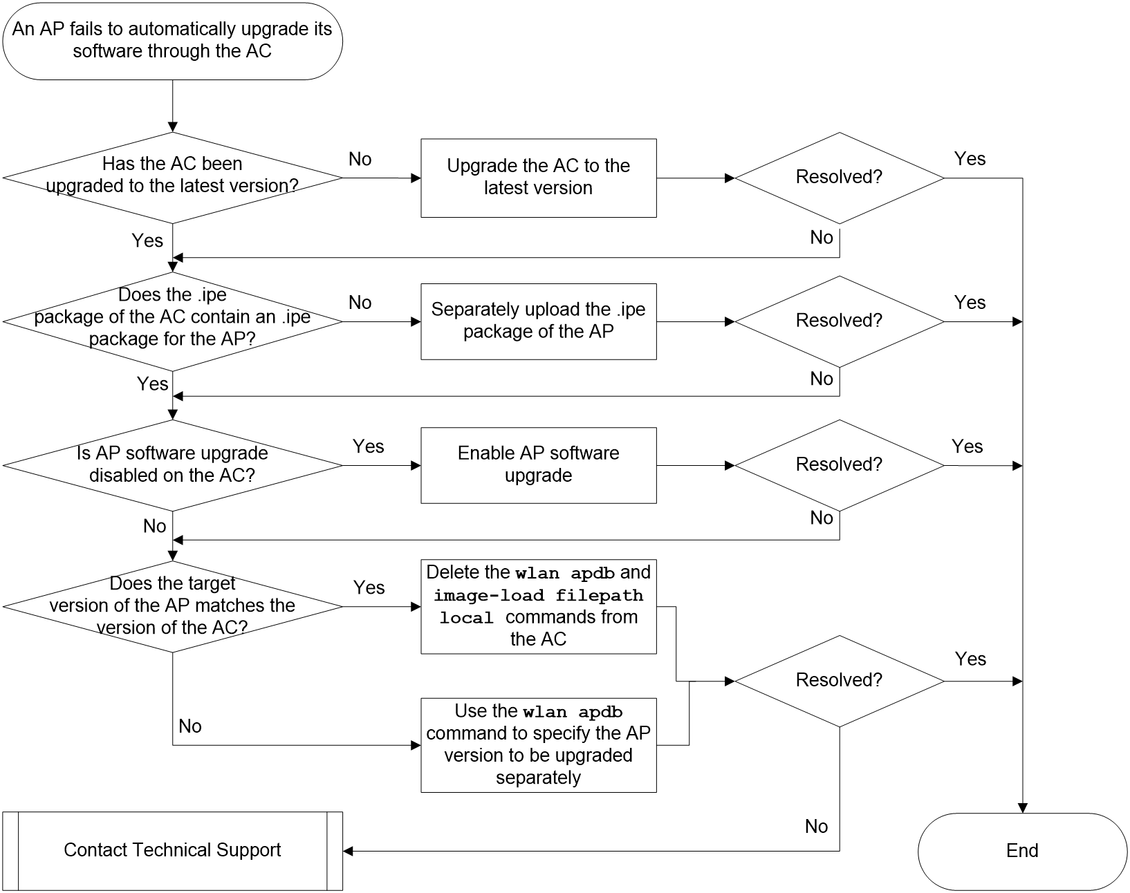
Solution
1. Execute the display version command to verify that the AC software has been upgraded to the latest version.
¡ If the AC software has been upgraded, go to the next step.
[Sysname] display version
H3C Comware Software, Version 7.1.064, ESS 5568
Copyright (c) 2004-2021 New H3C Technologies Co., Ltd. All rights reserved.
H3C WX2560X uptime is 1 week, 0 days, 8 hours, 10 minutes
¡ If the AC software has not been upgraded, re-upgrade the AC software according to the release notes for the latest software version.
2. Read the release notes to obtain information about the .ipe package of the AP, and then execute the dir apimge command to check whether the .ipe package of the AC contains an .ipe package for the AP and verify that the size of the AP .ipe package is correct.
¡ If the .ipe package of the AC contains an .ipe package for the AP and the AP .ipe package is correct, go to the next step.
<Sysname> dir apimge
Directory of cfa0:/apimge
0 -rw- 14518272 Jun 07 2021 03:56:22 wa4300h.ipe
1 -rw- 14533632 Jun 07 2021 03:56:16 wa4300s.ipe
2 -rw- 23323648 Jun 07 2021 03:56:18 wa5300.ipe
3 -rw- 48217088 Jun 07 2021 03:56:32 wa6300.ipe
4 -rw- 48883712 Jun 07 2021 03:57:00 wa6300a.ipe
5 -rw- 36919296 Jun 07 2021 03:56:26 wa6500.ipe
6 -rw- 52670464 Jun 07 2021 03:57:06 wa6500a.ipe
7 -rw- 50496512 Jun 07 2021 03:57:12 wa6500b.ipe
8 -rw- 63531008 Jun 07 2021 03:56:38 wa6600.ipe
¡ If the .ipe package of the AC does not contain an .ipe package for the AP or the AP .ipe package is abnormal, access the official website to download the compressed software image package for the AP on the Support > Resource Center > Software Download > Wireless page. After decompressing the package, upload the required AP images to the apimge directory of the AC.
|
|
NOTE: The .ipe packages of the WX2500H series and WX3010H series ACs do not contain the .ipe packages of some AP models. For more information, see the release notes for the ACs. The ipe packages of the other ACs by default contain the .ipe packages of all AP models. |
3. On the AC, check whether the firmware-upgrade disable command is used in AP view, AP group view, or global configuration view. By default, the firmware-upgrade enable command applies.
¡ If the firmware-upgrade disable command is used, the AC does not examine the software version of the AP or notify the AP to download new software images. You must use the undo firmware-upgrade to enable the software upgrade feature for the AP.
# AP view.
<Sysname> system-view
[Sysname] wlan ap ap3 model WA6320
[Sysname-wlan-ap-ap3] firmware-upgrade disable
# AP group view.
<Sysname> system-view
[Sysname] wlan ap-group group1
[Sysname-wlan-ap-group-group1] firmware-upgrade disable
# Global configuration view.
<Sysname> system-view
[Sysname] wlan global-configuration
[Sysname-wlan-global-configuration] firmware-upgrade disable
¡ If the firmware-update disable command is not used, go to the next step.
4. Execute the display wlan ap-model name model-name command to verify that the target version of the AP matches the version of the AC.
|
|
NOTE: You must use the firmware-update enable command to enable version check if the software version specified by using the wlan apdb command has higher priority than the version matched by default between the AC and AP. |
¡ If the target version of the AP does not match the version of the AC, execute the wlan apdb command on the AC to specify the target image package for separately upgrading the AP.
<Sysname> system-view
[Sysname]wlan apdb WA6320 Ver.C E2108
[Sysname]wlan image-load filepath local //Download the images in the specified location.
¡ If the target version of the AP matches the version of the AC, remove the wlan apdb and image-load filepath local commands from the AC and retains the firmware-update enable command.
5. If the issue persists, collect the command output related to software upgrade for the following commands on the AC and AP, and contact Technical Support:
<Sysname> debugging wlan capwap error all
<Sysname> terminal debugging
The current terminal is enabled to display debugging logs.
<Sysname> terminal monitor
The current terminal is enabled to display logs.
Failure to manually upgrade AP software from the BootWare menu
Symptom
Software upgrade fails for an AP when you manually upgrade the software from one Comware 7 version to another Comware 7 version through the BootWare menu.
Possible reasons
The common reasons of this issue include the following:
· The imported upgrade software images are incorrect.
· Configuration error, for example, IP or download path error.
· An exception occurs for the upgrade software images.
· The storage space is insufficient on the AP.
Analysis
Figure 25 shows the diagnostic process of this type of fault.
Figure 25 Problem analysis flowchart
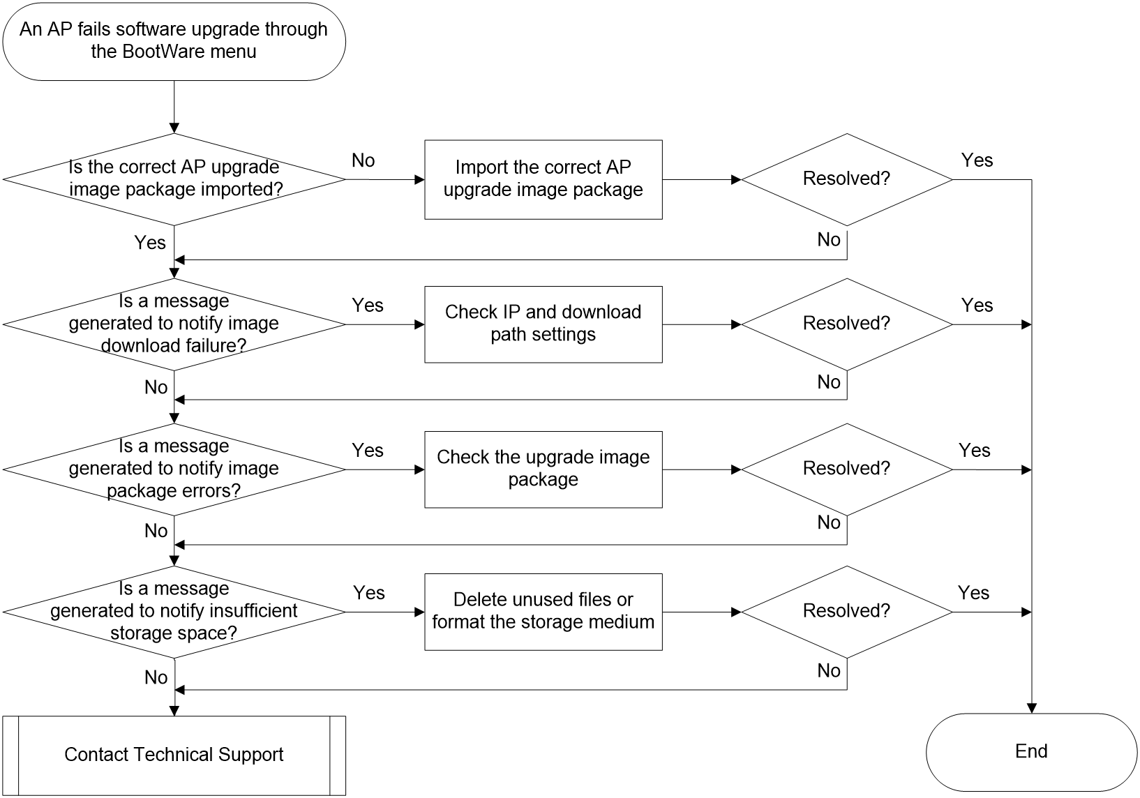
Solution
|
|
IMPORTANT: A Comware 7 software image package does not separately store the .ipe image package of the AP. To manually import the new version of software image package to the AP, you must first obtain the correct .ipe image package and then import the image package through the BootWare menu. You can download the .ipe image package from the apimage folder on the AC or obtain it by contacting Technical Support. |
1. Execute the display version command to check the version information and verify that the imported images are the desired upgrade images.
¡ If the version information is correct, go to the next step.
¡ If the version information is incorrect, copy the correct upgrade images to the server and upgrade the AP software according to the release notes for the new version.
<H3C> display version
H3C Comware Software, Version 7.1.064, Release 2449P01
Copyright (c) 2004-2022 New H3C Technologies Co., Ltd. All rights reserved.
H3C WA6320 uptime is 0 weeks, 0 days, 0 hours, 0 minutes
Last reboot reason : User soft reboot
Boot image: flash:/wa6300-boot.bin
Boot image version: 7.1.064, Release 2449P01
Compiled Jul 19 2021 16:00:00
System image: flash:/wa6300-system.bin
System image version: 7.1.064, Release 2449P01
Compiled Jul 19 2021 16:00:00
|
|
NOTE: In this example, TFTP is used. The value in the Load File Name field must be the same as the name of the image package to be downloaded. The value in the Target File Name filed represents the name of the image package after it is downloaded. By default, the target file name is the same as the file name on the server. The value in the Server IP Address field represents the IP address of the TFTP or FTP server. The value in the Local IP Address field must belong to the same subnet as the value in the Server IP Address field. The value in the Gateway IP Address field retains 0.0.0.0. |
==========================<ETHERNET PARAMETER SET>==========================
|Note: '.' = Clear field. |
| '-' = Go to previous field. |
| Ctrl+D = Quit. |
============================================================================
Protocol (FTP or TFTP) :tftp
Load File Name :wa6300.ipe
:
Target File Name :wa6300.ipe
:
Server IP Address :192.168.1.1
Local IP Address :192.168.1.253
Subnet Mask :0.0.0.0
Gateway IP Address :0.0.0.0
2. Check whether the following messages have been generated during the upgrade process and take measures accordingly:
¡ If the Loading Failed! message has been generated, image downloading fails. In this case, check the following items:
- Verify that the TFTP download path is correct.
- Verify that the TFTP port is in listening state.
- Verify that the PC and AP have wired connectivity at Layer 2.
- Verify that the server IP address is correctly configured.
- Verify that the local IP address and the server IP address belong to the same subnet.
¡ If the Something wrong with the file! message has been generated, the upgrade image package has errors. If the image package has errors, the AP generates the Booting App fails! message when it starts up.
- Verify that the target file name of the image package is correct, especially that underscores (_) and hyphens (-) are distinguished.
- Verify that you upload a fat version in fat mode or upload a fit version in fit mode. Do not upload a fat version in fit mode or upload a fit version in fat mode.
- Check the file size to verify that the downloaded image package is intact, and verify that the image package is compatible with the AP model.
¡ If the The space is not enough Failed! message has been generated, the storage space is insufficient. In this case, delete unused files from the AP or format the storage medium of the AP, and then import the upgrade image package to the AP.
¡ If none of the above messages has been generated, the system outputs the following message after the image package is downloaded successfully:
Loading.....................................................................
............................................................................
............................................................................
............................................................................
............................................................................
............................................................................
............................................................................
............................................................................
............................................................................
.....................................Done.
36462592 bytes downloaded!
Image file wa6300-boot.bin is self-decompressing...
Saving file flash:/wa6300-boot.bin .................................Done.
Image file wa6300-system.bin is self-decompressing...
Saving file flash:/wa6300-system.bin .......................................
................................Done.
3. If the issue persists, collect all messages generated during AP upgrade, and contact Technical Support.
For example, the following information is generated when the AP starts up:
BootWare Validating...
Press Ctrl+B to enter extended boot menu...
...
System image is starting...
Startup configuration file doesn't exist or is invalid.
Line con0 is available.
Press ENTER to get started.
Unexpected disconnection of a fit AP
Symptom
In a network with both ACs and fit APs deployed, an AP goes offline unexpectedly when the network is operating correctly.
Possible reasons
In a network with both ACs and fit APs deployed, communication between ACs and APs is through the control and provisioning of wireless access points (CAPWAP) tunnel. An AP comes online by following this flow: the AP obtains the AC address, the AP discovers the AC, the AP connects to the AC, the AC issues configuration to the fit AP, and the devices maintain the CAPWAP tunnel and update the tunnel configuration. The AP can register with the AC and operate stably only after the six steps are completed successfully.
If the network is operating correctly, the common reasons of this issue include the following:
· AP reboot due to power-off.
· The link between the AC and AP is not working correctly.
· The CPU or memory usage of the AC is too high.
· The CPU or memory usage of the AP is too high.
· The AC does not have a system software file for the AP, or the system software file is abnormal.
· Misconfiguration on the AC or AP.
Analysis
To troubleshoot this issue:
1. Check the running status and reason for disconnection of the AP.
2. Verify that the link between the AC and AP is operating correctly.
3. Check whether the operation status and configuration of the AC and AP are normal.
4. Analyze the problem by collecting debugging information from the AC and AP.
Figure 26 shows the diagnostic process of this type of fault.
Figure 26 Problem analysis flowchart
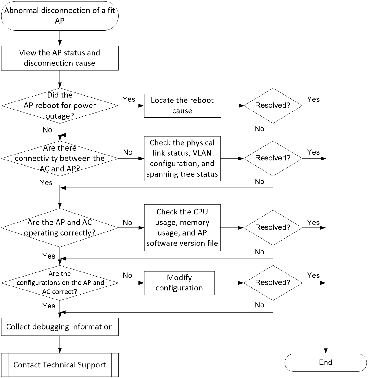
Solution
To resolve this issue:
1. View the AP status.
Use one of the following methods:
¡On the AC, execute the display wlan ap name ap-name command and examine the State field.
- If the state is I, the AP is offline.
- If the state is R/M, the AP has come online and established a master tunnel with the master AC.
- If the state is R/B, the AP has come online and established a backup tunnel with the backup AC.
- For more information about the AP states, see AP Management Command Reference.
# Display information about AP ap1.
<Sysname> display wlan ap name ap1
AP information
State : I = Idle, J = Join, JA = JoinAck, IL = ImageLoad
C = Config, DC = DataCheck, R = Run M = Master, B = Backup
AP name APID State Model Serial ID
ap1 1 I WA6320 219801A28N819CE0002T
¡On the AC, execute the display wlan ap all connection-record command to view AP connection records.
- If the state is Run, the AP has come online. The Time field displays the duration of the CAPWAP tunnel.
- If the state is Offline, the AP has gone offline. The Time field displays the most recent time when the AP established a CAPWAP tunnel with the AC.
# Display the connection records for all APs.
<Sysname> display wlan ap all connection-record
AP name IP address State Time
ap1 192.168.100.27 Run 01-06 09:06:40
2. View the reason for AP disconnection.
On the AC, execute the display wlan ap name ap-name verbose command and examine the Online time, System uptime, and Tunnel down reason fields. The descriptions for these fields are as follows:
¡Online time—Duration of time that the AP is online.
¡System uptime—Duration of AP system startup.
¡Tunnel down reason—reason for the CAPWAP tunnel closure. If the AP experiences link interruption after successfully connecting with the AC, this display field will record the reason detected by the AC for link disconnection. Table 5 shows the common causes of AP disconnection. For more information about the Tunnel down reason field, see AP Management Command Reference.
Table 5 Values of the Tunnel down reason field
|
Value |
Description |
|
Neighbor dead timer expired |
The neighbor report timer expired, because the AC had not received Echo request messages from the AP within three times the handshake time. |
|
Request wait timer expired |
The request wait timer expired, because the AC sent a response-required control message to the AP, and the AP did not respond within the designated time. |
|
Processed join request in Run state |
After the CAPWAP tunnel was established between the AC and AP, the Join Request message was received and processed in Run state, and tunnel disconnection occurred. |
|
Failed to retransmit message |
Message retransmission failed. |
|
AP was reset due to inconsistent local and reported radio statistics |
The local and reported radio statistics are inconsistent. |
|
AP was reset |
An AP restart caused CAPWAP tunnel disconnection. |
If the online duration of the AP is similar to the AP system startup duration, and the Tunnel down reason field displays AP was reset, it indicates that the AP restart caused the disconnection. To further locate the cause of the AP restart, see the troubleshooting process for AP restart. Otherwise, go to step 3.
<Sysname> display wlan ap name ap1 verbose
AP name : ap1
AP ID : 1
AP group name : default-group
State : Run
Backup type : Master
Online time : 0 days 1 hours 25 minutes 12 seconds
System uptime : 0 days 2 hours 22 minutes 12 seconds
Model : WA6320
Region code : CN
...
Last reboot reason (AP check) : The radio physical status was down
Last reboot reason (AC check) : The radio physical status was down
Latest IP address : 10.1.0.2
Current AC IP : 192.168.1.1
Tunnel down reason : Request wait timer expired
…
3. Check if the link between the AC and AP is operating correctly.
If the network between the AC and AP is not connected, the AP cannot go online. On the AC and AP, execute the ping command to ping each other. The CAPWAP tunnel is sensitive to packet loss on the link between the AC and AP, and requires a wired packet loss rate of less than 0.1%. The link must support an MTU of 1500 bytes.
On the AC, use 1472-byte packets to ping the AP (MTU 1500 bytes) with fragmentation disabled to test the connectivity between the AP and AC.
<Sysname> ping -s 1472 -f 192.168.100.27
PING 192.168.100.27: 1472 data bytes, press CTRL_C to break
Reply from 192.168.100.27: bytes=1472 Sequence=1 ttl=21 time=20 ms
Reply from 192.168.100.27: bytes=1472 Sequence=2 ttl=21 time=20 ms
Reply from 192.168.100.27: bytes=1472 Sequence=3 ttl=21 time=20 ms
Reply from 192.168.100.27: bytes=1472 Sequence=4 ttl=21 time=20 ms
¡If the ping operation fails, check for issues about the physical link, VLAN configuration, and STP status, and if the IP address has expired.
¡Check for network loops in case of excessive delay or packet loss.
¡If there is no packet loss and the delay is normal during the ping test, proceed to the next step.
4. Check the operating status of the AC and AP.
¡Check the CPU usage and memory usage of the AC and AP.
Execute the display cpu-usage and display memory commands to view the CPU usage and memory usage.
# Execute the CPU usage statistics of the device.
<Sysname> display cpu-usage
Unit CPU usage:
70% in last 5 seconds
71% in last 1 minute
75% in last 5 minutes
# Display the memory usage statistics of the device.
<Sysname>display memory
Memory statistics are measured in KB:
Slot 1:
Total Used Free Shared Buffers Cached FreeRatio
Mem: 1974712 718496 1256216 0 9740 282512 64.3%
-/+ Buffers/Cache: 426244 1548468
Swap: 0 0 0
If the CPU usage exceeds 70%, the CPU status is abnormal. Locate the cause as follows:
- Execute the display process cpu command to view the CPU usage of all processes and identify the processes that have been occupying the CPU for a long time.
- Check if major operations are performed on the network, such as version upgrades, network-wide configuration changes, device power outages, or device restarts.
If the CPU usage exceeds 70% and continues increasing, the CPU status is abnormal. Locate the cause as follows:
- Execute the display process memory command to view the memory usage of all processes and identify the processes that have been occupying the memory for a long time.
- Check if major operations are performed on the network, such as device information collection by a new NMS and configuration addition.
- Execute the display logbuffer commmand to view and collect alarms and logs.
¡Check if the software version files of the AC and AP match.
The fit AP versions are released with AC versions. Software version consistency between the AC and AP is required for the AP to come online on the AC. Causes of AC and AP version mismatch include the following:
- The AC does not support management of the AP model.
- Version compatibility issues exist between the AC and AP, or the software version file is abnormal.
Check if the AC can manage the current AP by checking the AP compatibility matrix in the AC's release notes. If the fit AP model is not in the package list, the IPE file for the AP is not included in the IPE file for the AC. If there is a need for using this type of AP in the current location, manually upload the AP version file to the /apimge directory on the AC. You can obtain unpackaged IPE files for APs in the corresponding AC ZIP version file.
On the AC, execute the dir command to check whether the AC has a software version file for the AP, the AP software version file matches the AC software version file, and the size of the software version files is correct.
<Sysname> dir flash:/apimge
Directory of flash:/apimge
0 -rw- 19171328 Jul 20 2022 23:51:00 wa4300.ipe
1 -rw- 14518272 Jul 20 2022 23:52:42 wa4300h.ipe
2 -rw- 14533632 Jul 20 2022 23:51:17 wa4300s.ipe
3 -rw- 18617344 Jul 20 2022 23:51:59 wa4600.ipe
4 -rw- 23329792 Jul 20 2022 23:52:26 wa5300.ipe
5 -rw- 19996672 Jul 20 2022 23:51:39 wa5600.ipe
6 -rw- 36929536 Jul 20 2022 23:53:24 wa6500.ipe
1015808 KB total (744748 KB free)
5. Check for errors in the AC-side configuration, including:
¡Check the installation and validity period of the license.
Execute the display license command or access the Web interface to verify that the device has a license within the validity period installed. Install a new license within the validity period of the one in use to avoid expiration of the current license and impact on corresponding business operations.
# Display detailed information about all licenses on the device.
<Sysname> display license
flash:/license/210235A1JMC1660000282021060717343842697.ak
Feature: APMGR
Product Description: Enhanced Access Controller License,8 APs,for Verticals,for V7
Registered at: 2021-06-07 17:01:55
License Type: Trial (days restricted)
Trial Time Left (days): 0
Current State: Expired
Pre-installed License
Feature: APMGR
Feature Description: PreAtom This is APMGR license
Time Left (days): 0
Current State: Expired
¡Check the remaining license resources and the maximum number of APs managed by the AC.
The number of APs allowed to go online by the AC is limited by both the maximum AP quantity supported by the license and the maximum managed AP quantity. Execute the display wlan ap all command to view the maximum number of managed APs and the number of available resources supported by the license.
# Display information about all APs.
<Sysname> display wlan ap all
Total number of APs: 3
Total number of connected APs: 3
Total number of connected manual APs: 3
Total number of connected auto APs: 0
Total number of connected common APs: 3
Total number of connected WTUs: 0
Total number of inside APs: 0
Maximum supported APs: 2048
Remaining APs: 2045
Total AP licenses: 128
Local AP licenses: 128
Server AP licenses: 0
Remaining local AP licenses: 125
Sync AP licenses: 0
AP information
State : I = Idle, J = Join, JA = JoinAck, IL = ImageLoad
C = Config, DC = DataCheck, R = Run M = Master, B = Backup
AP name APID State Model Serial ID
ap1 1 R/M WA6320 219801A28N819CE0002T
ap2 2 R/M WA6320 219801A28N819CE0003T
ap3 3 R/M WA6320 219801A28N819CE0004T
¡Check for errors in the configuration related to the AP.
¡Execute the display current-configuration configuration wlan-ap command to view AP configuration. If you issue configuration to a specific AP through a MAP file, examine the content of the MAP file.
¡# Display configuration related to APs.
<Sysname> display current-configuration configuration wlan-ap
#
wlan ap ap1 model WA6320
serial-id 219801A2YF819BE002X6
map-configuration flash:/map.txt
radio 1
radio 2
radio enable
service-template hello
gigabitethernet 1
#
¡# Display the contents of the map.txt file.
<Sysname> more flash:/map.txt
System-view
vlan 200
interface gigabitethernet1/0/1
port link-type trunk
port trunk permit vlan 200
6. Check AP configuration.
View the configuration of the uplink interface of the AP. On the AP, execute the display current-configuration interface command to check whether the uplink interface configuration has been modified.
Check whether the wlan management-vlan command is used to configure a management VLAN for the AP. Check if the intermediate network devices allow the management VLAN if the management VLAN ID is modified on the AP.
7. If the issue persists, collect the following information, and contact Technical Support:
¡Execution results of the above steps.
¡Device configuration files, log information, and alarm messages.
¡Debugging command output.
|
|
IMPORTANT: Before debugging, check the CPU and memory usage to ensure that debugging will not affect device operation. Disable debugging once information collection is complete. |
To display debugging information on the console, perform the following tasks:
a. Execute the terminal debugging command to enable outputting debugging information to the current terminal.
b. Execute the info-center enable command to enable information center. By default, this feature is enabled.
c. Execute the debugging command to enable debugging for service modules. For example, use the debugging wlan capwap command to enable CAPWAP debugging, and service modules will generate debugging log messages.
The monitoring terminal refers to the user terminal logged in via VTY type user lines. To display debug information on the monitoring terminal, perform the following tasks:
a. Execute the terminal monitor command to enable outputting log information to the current terminal. Execute the terminal debugging command to enable outputting debugging information to the current terminal.
b. Execute the info-center enable command to enable information center. By default, this feature is enabled.
c. Execute the debugging command to enable debugging for service modules.
Random disconnection of a barcode scanner
Symptom
The barcode scanner network is randomly disconnected.
Possible reasons
Common causes of this type of fault include:
· The signal value of the barcode scanner does not meet the requirements.
· The AP experiences interference on the radio interface.
· Different encryption methods result in problems with barcode scanner association.
· The barcode scanner is operating in power-saving or sleep mode.
· The barcode scanner version is too low or the NIC is too old.
Analysis
Figure 27 shows the diagnostic process of this type of fault.
Figure 27 Problem analysis flowchart

Solution
1. Check if the signal value of the barcode scanner meets the requirements.
Wireless message exchange is a bidirectional transmission process, and the signal strength of the endpoint perceived by the device is the signal strength of the wireless endpoint feedback message received by the AP.
On the AC, execute the mac-address command to view the endpoint signal strength. Specify the MAC address of the barcode scanner.
<AC> display wlan client mac-address mac-address verbose | include RSSI
RSSI : 30
Typically, the RSSI of an endpoint is required to be larger than 30. If the RSSI is smaller than 25, the actual packet transmission rate of the endpoint will decrease significantly. If the RSSI is smaller than 20, the wireless endpoint is basically unusable.
The working environment for barcode scanners is usually warehouses in logistics. Weak signal values might affect the quality of response messages. As a best practice, check the environment as follows:
¡Whether obvious obstruction or attenuation exists, such as a physical wall, within the range of the barcode scanner operation.
¡Check if the barcode scanner is connected to a remote AP.
¡Check the placement and deployment of on-site APs to ensure optimal signal strength for endpoint connections.
2. View AP radio interface interference.
The radio interface usage reflects the channel's busy level, and this value fluctuates in real time. Higher wireless signal frequency leads to greater attenuation. Most barcode scanners have outdated NIC performance and can only connect to the 2.4G frequency band. Due to limited 2.4G spectrum resources and greater attenuation on 5G, which is also an industrial open frequency band susceptible to interference, pay attention to the radio interface usage of the 2.4G band and minimize environmental impact.
On the AC, you can quickly view the current radio interface usage of all APs (collected every 50 seconds) to gain a basic understanding of the entire network environment. The radio frequency on the AP shows the changes in the radio interface within 200 seconds (with a 10-second interval). As a best practice, check the radio interface usage on the AP.
View the radio interface usage on the AC.
<AC> display wlan ap all radio
Total number of APs: 1
……
AP name RID State Channel BW Usage TxPower Clients
(MHz) (%) (dBm)
7c1e-067a-8140 1 Up 52(auto) 80 8 18 0
7c1e-067a-8140 2 Up 149(auto) 80 22 20 0
7c1e-067a-8140 3 Up 6(auto) 20 19 20 1
RIDs 1, 2, and 3 respectively represent RF1, RF2, and RF3, while the Usage field represents the radio interface usage.
View radio interface usage on the AP. Log in to the AP, enter probe view, and check the radio interface usage in Tx and Rx directions.
[ap] probe
[ap-probe] display ar5drv 2 channelbusy
ChannelBusy information
Ctl Channel: 08 Channel Band:20M
Record Interval(s): 9
Date/Month/Year: 23/11/2019
Time(h/m/s): CtlBusy(%) TxBusy(%) RxBusy(%) ExtBusy(%)
01 19:11:56 4 0 3 0
02 19:11:47 8 0 5 0
03 19:11:38 7 0 4 0
3. Check for issues caused by different encryption methods.
Try unencrypted, RSN+CCMP, and WPA+TKIP combined encryption methods and observe if there are any issues with the scanner's association.
4. Check the endpoint operating mode.
a. Check whether the barcode scanner is operating in power-saving or sleep mode.
b. Check the sleep times of the barcode scanner on the AC to see if the barcode scanner enters sleep mode frequently. If this condition exists, Internet access on the endpoint will be affected, especially when the endpoint is mobile (roaming) or has a weak signal. To address the issue of excessive sleep sessions, you can alleviate it by configuring client keep-alive on the device side. When the wireless client enters sleep mode, it determines if the AP has cached the message by periodically listening to the Traffic Indication Map (TIM) in Beacon frames. If the AP has cached the message, the wireless client terminates sleep mode and communicates with the AP. Use the option keep-active enable command to shorten the client's sleep time. The AP will modify the TIM in the Beacon frame to improve transmission efficiency. However, the root cause of the issue is related to the sleep mechanism of the client NIC. As a best practice, check the operating mode of the barcode scanner.
# Check the number of client sleep times:
<AC> display wlan client mac-address mac-address verbose
…
Sleep count : 35737
…
RSSI : 22
5. Check the model and version of the barcode scanner.
a. Confirm the model and version of the barcode scanner. If the current version is too low, upgrade the barcode scanner and NIC driver to the latest versions.
b. Set the 802.11g radio mode.
Some barcode scanners come with older NICs, and to match their Wi-Fi mode, the radio frequency can be configured to 802.11g radio mode.
[AC] wlan ap ap1 model model-name
[AC-wlan-ap-ap1] radio 2
[AC-wlan-ap-ap1-radio-2] type dot11g
c. Disable the 5.5 transmission rate
Based on troubleshooting experience, some Motorola barcode scanners do not have good support for the 5.5 rate, resulting in disconnection during negotiating at this speed. Disable this transmission rate and observe whether the issue persists.
[AC] wlan ap ap1 model model-name
[AC-wlan-ap-ap1] radio 2
[AC-wlan-ap-ap1-radio-2] rate disabled 5.5
d. Set the preamble type.
The preamble is a group of bits located at the beginning of a packet, which allows the receiver to synchronize and prepare for data reception. Only RF modes of 802.11b, 802.11g, or 802.11gn support the configuration of preamble types. A short preamble can improve network synchronization performance. By default, H3C devices use the short preamble, but some early client NICs use the long preamble. You can set the long preamble for compatibility with these client NICs.
# Set the preamble type to long preamble. (Radio view)
[AC] wlan ap ap1 model model-name
[AC-wlan-ap-ap1] radio 2
[AC-wlan-ap-ap1-radio-2] type dot11g
[AC-wlan-ap-ap1-radio-2] preamble long
6. Capture packets on a third-party NIC.
Capture radio interface packets by using a wireless capture NIC during the fault occurrence.
a. Record the MAC or IP address of the faulty endpoint and keep the symptoms of the malfunction to prevent the problem from disappearing due to client re-association.
b. On the AC, execute the display wlan client | include X.X.X.X command to identify the AP associated with the endpoint.
c. Execute the display wlan ap all radio command to view the channels of the AP.
d. Install a wireless capture NIC, open the Omnipeek software, select the channel of the associated AP in the 802.11 column.
Figure 28 Select a channel.
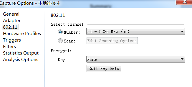
e. Enter the client's MAC address in the Filters column and select bidirectional.
Figure 29 Filter client MAC addresses.
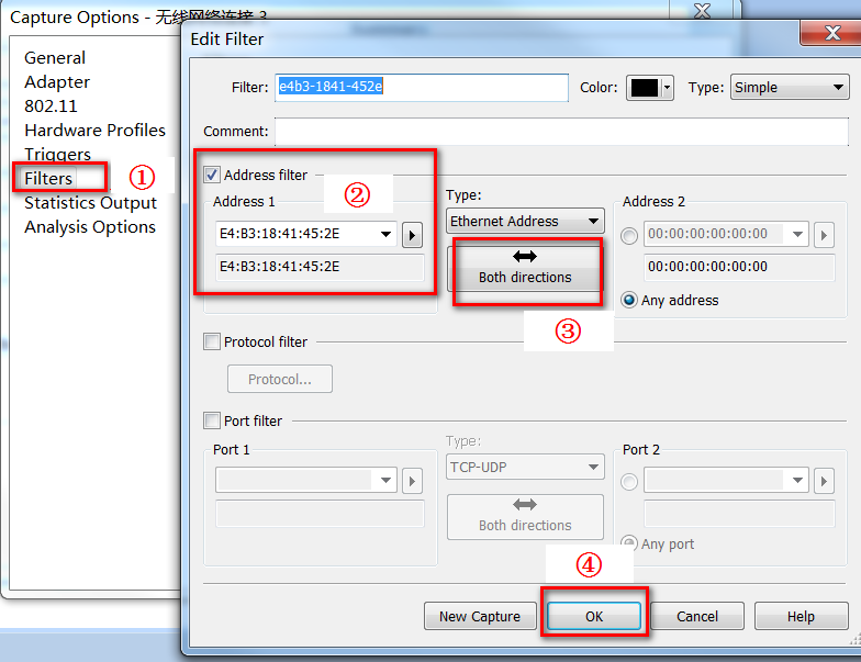
f. Click Start Capture in the top right corner to begin packet capturing.
Figure 30 Starting capturing packets
7. If the issue persists, contact Technical Support.
Slow wireless NIC speed in centralized forwarding mode
Symptom
In the AC+fit AP network architecture, the client data packets can be forwarded by either the AC or AP.
· Centralized forwarding—Client data packets are forwarded by the AC. Client data traffic is sent from the AP to the AC through a CAPWAP tunnel and then the AC forwards the data packets.
· Local forwarding—Client data packets are directly forwarded by the AP. Forwarding data packets on the AP can alleviate data forwarding pressure on the AC.
In this document, the "slow wireless NIC speed in centralized forwarding mode" issue means that the slow wireless NIC speed issue does not occur in local forwarding mode or on the wired network in the same conditions. Specific symptoms include slow webpage access on wireless endpoints and choppy video playback. The direct symptom is that high delay and packet loss exist when the gateway is pinged from a wireless endpoint in centralized forwarding mode.
Possible reasons
The common reasons of this issue include the following:
· The wired link between the AC and gateway has an anomaly.
· The broadcast/multicast packet ratio of the wired interfaces is too high.
· The wired interfaces experience an instantaneous high traffic burst.
· The forwarding processes of the AC are too busy, resulting in wireless packet loss.
· The quality of the air interfaces on the AP is poor.
Analysis
To troubleshoot this type of fault:
1. Ping the gateway from the AC to check for anomalies in the wired link between the AC and the gateway.
2. Explore the regularity of faults, and observe whether they are strongly related to specific time ranges and network traffic models.
3. View the packet statistics of the wired interfaces on the AC.
4. Identify whether the forwarding processes of the AC are occupying the CPU for a long time.
5. Identify whether the quality of the air interfaces on the AP is poor
Figure 31 shows the diagnostic process of this type of fault.
Figure 31 Problem analysis flowchart

Solution
As a best practice, follow these steps to trouble this type of fault:
1. Identify whether an anomaly exists in the wired link between the AC and the gateway.
In the centralized forwarding architecture, the AC is typically attached to the switch. Ping the gateway from the AC to determine the fault scope and identify whether the wired link between the AP and gateway is operating normally.
¡If the ping operation fails, check for abnormal physical links, VLAN configuration, and STP state, and expired IP addresses.
¡If the delay is high or packets are lost, identify whether a loop exists on the link between the AC and the gateway. When a loop exists on the wired network, the AC will receive too many broadcast or multicast packets, causing the device to fail to process wireless packets. As a result, the network access speed of wireless users is impacted.
¡If ping packets are not lost and the delay is normal, the fault occurs on the link between wireless endpoint and AC. In this case, proceed to step 2.
2. Observe the correlation between faults and time ranges.
Identify whether the poor wireless network experience is related to specific time ranges. For example, in an office scenario, the wireless NIC speed is slow in some office time ranges but normal in other time ranges. In a university dormitory scenario, the wireless NIC speed is obviously slow during non-teaching time ranges.
¡If wireless network experience is poor and strongly related to time ranges, the fault might be caused by traffic changes in the network. In this case, review traffic in the wired network.
¡Execute step 3 if wireless performance is poor and not related to time ranges.
3. Check the ratio of non-unicast packets received or sent through the wired interfaces on the AC.
If the wired interfaces on the AC receive or send significantly more broadcast or multicast packets than unicast packets, excessive broadcast or multicast traffic exist in the network. In this case, review the wired network traffic and identify whether the interfaces are assigned to too many VLANs or whether a broadcast storm exists. More specifically:
a. Clear the packet statistics on the uplink interface of the AC.
To view the statistics clearly, execute the reset counter interface command to clear packet statistics of the AC interface and modify the statistics polling interval to 5 seconds (300 seconds by default).
<Sysname> reset counters interface gigabitethernet 1/0/1
<Sysname> system-view
[Sysname] interface gigabitethernet 1/0/1
[Sysname-GigabitEthernet1/0/1]flow-interval 5
b. View the packet statistics of the interface.
Execute the display interface command every few seconds in any view to view the packet statistics of the interface.
# View the statistics for Ethernet interface GigabitEthernet 1/0/1.
<Sysname> display interface GigabitEthernet 1/0/1
GigabitEthernet1/0/1
Current state: DOWN
Line protocol state: DOWN
IP packet frame type: Ethernet II, hardware address: fc60-9ba1-81e0
Description: GigabitEthernet1/0/1 Interface
...
Last time when physical state changed to up:-
Last time when physical state changed to down:-
Last 5 seconds input: 511025 packets/sec 405002105 bytes/sec 8%
Last 5 seconds output: 685075 packets/sec 426870884 bytes/sec 8%
Input (total): 58328063 packets, 21043223173 bytes
27274961 unicasts, 14726456 broadcasts, 16326646 multicasts, 0 pauses
...
Output (total): 25964106 packets, 6817109645 bytes
25756796 unicasts, 431 broadcasts, 206879 multicasts, 0 pauses
...
Focus on the fields in Table 6 in the command output.
Table 6 Important information in the display interface command output
|
Field |
Description |
|
Last 5 seconds input: 511025 packets/sec 405002105 bytes/sec 8% Last 5 seconds output: 511025 packets/sec 405002105 bytes/sec 8% |
Average inbound or outbound traffic rate (in pps and Bps) in the last statistics polling interval, and the ratio of the actual rate to the interface bandwidth. To set the statistics polling interval, use the flow-interval command. |
|
Input (total): 58328063 packets, 21043223173 bytes 27274961 unicasts, 14726456 broadcasts, 16326646 multicasts, 0 pauses |
Inbound traffic statistics (in packets and bytes) for the interface. All inbound normal packets, abnormal packets, and normal pause frames were counted. The number of inbound unicast packets, the number of inbound broadcasts, the number of inbound multicasts, and the number of inbound pause frames. |
|
Output (total): 25964106 packets, 6817109645 bytes 27274961 unicasts, 14726456 broadcasts, 16326646 multicasts, 0 pauses |
Outbound traffic statistics (in packets and bytes) for the interface. All inbound normal packets, abnormal packets, and normal pause frames were counted. The number of outbound unicast packets, the number of outbound broadcasts, the number of outbound multicasts, and the number of outbound pause frames. |
- Based on the Input (total) and Output (total) fields, check the ratios of unicast, broadcast, and multicast packets passing through the wired interfaces on the AC. Identify whether the broadcast and multicast packet ratios are too high. If the number of broadcast or multicast packets is significantly greater than the number of unicast packets, excessive broadcast or multicast traffic exists in the network. In this case, review the wired network traffic and identify whether the interfaces are assigned to too many VLANs or whether a broadcast storm exists.
- In centralized forwarding mode, CAPWAP encapsulation and decapsulation are performed for service packets on the AC. If the AC incorporates N APs on the network, the AC duplicates the packet N times and sends them to the N APs upon receiving a broadcast packet of a service VLAN from the uplink network. This processing significantly consumes the CPU resources of the AC, making the AC busy. Additionally, when broadcast packets are transmitted at the minimum rate over the air interfaces, a lot of air interface resources will be occupied to impact the wireless network.
Identify whether the number of outbound packets is significantly greater than the number of inbound packets on the access interface of the AC by viewing Last 5 seconds input and Last 5 seconds output fields in the command output. If yes, broadcast packets are duplicated. In this case, review the network traffic and properly isolate broadcast and multicast packets.
a. (Optional.) View the packet statistics of the AC wired interfaces through the FPL statistics feature.
If the fault cannot be reproduced during troubleshooting, it means the fault occurred during a specific time range in the past. You can use the FPL statistics feature to view statistics of the packets received by the AC wired interfaces within the last seven days at a one-minute interval.
In probe view, execute the fpl-diag command. The value of XGE1/0/3RxBroadcast for the item field represents the broadcast packets received on interface XGE 1/0/3. The Delta field shows the growth rate of broadcast packets per minute. If a wired interface receives or sends a significant amount of broadcast or multicast packets that flap obviously, abnormal broadcast or multicast packets exist on the network. As a best practice, review the wired network.
|
|
NOTE: Support for the FPL statistics feature depends on the device model. |
# Display statistics within 100 minutes starting from 9:00 am on the 3rd of this month.
<Sysname> system-view
[Sysname] probe
[Sysname-probe] fpl-diag slot 1 showlogall 3,9,0,100
idx item date rx delta
9530 XGE1/0/3RxBroadcast 09:11:36 06/03/2020 2502814 3824
9531 XGE1/0/3RxBroadcast 09:12:36 06/03/2020 2506986 4172
9532 XGE1/0/3RxBroadcast 09:13:36 06/03/2020 2511841 4855
9533 XGE1/0/3RxBroadcast 09:14:36 06/03/2020 3443 0
9534 XGE1/0/3RxBroadcast 09:15:36 06/03/2020 3105 0
If no anomaly is found in the statistics of the AC interface, execute step 4.
4. Identify whether traffic spikes exist on the AC wired interface.
Identify whether instantaneous high bursty traffic is received or sent on the AC wired interface.
¡If yes, further check for a loop and broadcast storm in the network.
¡If not, execute step 5.
Perform the following steps:
a. Identify whether an Rx queue overruns on the wired interface.
Execute the display interface command every few seconds in any view to view the packet statistics of the interface. Focus on the overruns field: If the value for this field is not 0, a large amount of instantaneous high bursty traffic enters and leaves the interface. Because the Rx rate exceeds the processing capacity of the Rx queue, packets are dropped.
<Sysname> display interface gigabitethernet 1/0/1
GigabitEthernet1/0/1
Current state: UP
Line protocol state: UP
IP packet frame type: Ethernet II, hardware address: a4fa-7679-b6f0
...
Input (total): 58328063 packets, 21043223173 bytes
27274961 unicasts, 14726456 broadcasts, 16326646 multicasts, 0 pauses
...
Input: 31153 input errors, 0 runts, 0 giants, - throttles
0 CRC, - frame, 31153 overruns, 0 aborts
- ignored, - parity errors
...
b. Identify whether instantaneous bursty non-unicast traffic exists on the wired interface.
Broadcast traffic might not be constant, and it might be instantaneous high bursty traffic. Therefore, you might fail to detect the issue only by statistics of the interface. In this case, execute the display counters rate command every few seconds to view packet rate statistics of the interface.
If the average rate of receiving or sending broadcast (or multicast) packets is significantly higher than the average rate of receiving or sending unicast packets on the AC wired interface, instantaneous high bursty broadcast or multicast traffic exists in the network.
# Display the packet receiving rate statistics of the interface.
<Sysname> display counters rate inbound interface GigabitEthernet 1/0/1
Usage: Bandwidth utilization in percentage
Interface Usage (%) Total (pps) Broadcast (pps) Multicast (pps)
GE1/0/1 100 983276 669595 25518
Overflow: More than 14 digits.
--: Not supported
5. View CPU forwarding process of the AC.
Most protocol packets and some data packets are sent to the CPU for processing, regardless of whether the AC supports FPGA hardware forwarding.
a. Locate the processes that occupy the CPU for a long time.
Execute the display process cpu command on the AC to view the CPU usage of all processes and locate the processes that occupy the CPU for a long time. When the CPU usage of all forwarding processes (kdrvfwd) in the AC exceeds 50%, it means the forwarding processes are too busy, and wireless packets will be lost. The number of forwarding processes that an AC supports depends on the device model. For example, the WX5500H series AC has 16 forwarding processes. If the CPU usage of a forwarding process exceeds 2.5%, wireless packets might be lost. If the CPU usage of a forwarding process exceeds 3%, significant packet loss will occur.
- If the CPU forwarding processes of the AC are abnormal, proceed to step b.
- If the CPU forwarding processes of the AC are normal, proceed to step 6.
# Display the CPU usage statistics of the device.
<Sysname> display process cpu
CPU utilization in 5 secs: 51.4%; 1 min: 52.1%; 5 mins: 52.3%
JID 5Sec 1Min 5Min Name
...
308 3.2% 3.2% 3.2% [kdrvfwd16]
309 3.2% 3.2% 3.0% [kdrvfwd17]
310 3.2% 3.2% 3.2% [kdrvfwd18]
311 2.6% 3.2% 2.9% [kdrvfwd19]
312 3.2% 3.2% 3.2% [kdrvfwd20]
313 3.2% 3.2% 3.2% [kdrvfwd21]
314 3.2% 3.2% 3.2% [kdrvfwd22]
315 2.6% 3.2% 3.1% [kdrvfwd23]
316 3.2% 3.2% 3.2% [kdrvfwd24]
317 3.2% 3.2% 3.2% [kdrvfwd25]
318 3.2% 3.2% 3.2% [kdrvfwd26]
319 3.2% 3.2% 3.2% [kdrvfwd27]
320 3.2% 3.2% 3.2% [kdrvfwd28]
...
b. (Optional.) Use the FPL statistics feature to view packets dropped in the forwarding processes.
To identify whether packets are lost in forwarding processes, execute the fpl-diag command in probe view on the AC to view the statistics for the past seven days at a one-minute interval. The PoeDropPkt value for the item field indicates packets dropped by the forwarding processes. The Delta field displays the number of forwarded packets dropped per minute. If the Delta value for a forwarding process fluctuates significantly, packets are lost in the forwarding process.
|
|
NOTE: Support for the FPL statistics feature depends on the device model. |
# Display statistics within 100 minutes starting from 9:00 am on the 3rd of this month.
<Sysname> system-view
[Sysname] probe
[Sysname-probe] fpl-diag slot 1 showlogall 3,9,0,100
idx item date rx delta
9519 PoeDropPkt 09:00:36 06/03/2020 822506 10
9520 PoeDropPkt 09:01:36 06/03/2020 822521 15
9521 PoeDropPkt 09:02:36 06/03/2020 822540 19
9522 PoeDropPkt 09:03:36 06/03/2020 822596 56
9523 PoeDropPkt 09:04:36 06/03/2020 822608 12
9524 PoeDropPkt 09:05:36 06/03/2020 822638 30
9525 PoeDropPkt 09:06:36 06/03/2020 822665 27
9526 PoeDropPkt 09:07:36 06/03/2020 822690 25
9527 PoeDropPkt 09:08:36 06/03/2020 822707 17
9528 PoeDropPkt 09:09:36 06/03/2020 822722 15
9529 PoeDropPkt 09:10:36 06/03/2020 822739 17
9530 PoeDropPkt 09:11:36 06/03/2020 822755 16
9531 PoeDropPkt 09:12:36 06/03/2020 822781 26
c. Identify the reason for the AC forwarding processes to occupy the CPU for a long time.
The reason for the AC forwarding processes to occupy the CPU for a long time is as follows:
Firstly, identify whether the device supports hardware forwarding. Identify whether hardware forwarding is enabled if the device supports it. If hardware forwarding is disabled, wireless traffic will be processed by the CPU, causing increased CPU workload.
# Enable WLAN hardware fast forwarding.
<Sysname> system-view
[Sysname] undo wlan fast-forwarding hardware disable
If the device does not support hardware forwarding, all wireless data packets must be processed by the CPU. When a large number of wireless network devices and wireless clients exist on the WLAN network, the AC consumes most of the CPU resources for processing wireless data packets. In this case, the forwarding performance of the AC might reach the bottleneck. To resolve this issue, change the forwarding mode from centralized to local.
Next, identify whether any special service models exist.
If the majority of traffic on the wireless network is a large amount of TCP traffic (such as video traffic), try adjusting the max segment size (MSS) of the CAPWAP tunnel to avoid fragmenting big packets. This avoids the issue that the forwarding processes are busy because fragments are sent to the CPU for processing.
# Set the TCP MSS for the CAPWAP tunnel to 2000 bytes.
<Sysname> system-view
[Sysname]wlan tcp mss 2000
6. Check the quality of AP air interfaces.
On the WLAN network, air interfaces share the transmission media and can easily encounter quality issues. In the centralized forwarding architecture, the slow wireless NIC speed issue requires focus on interference and broadcast/multicast packet ratios of air interfaces. To check the AP air interface quality:
a. Remotely log in to the AP.
Open the console for the associated AP (opened by default). Telnet to the AP associated with the endpoint. The default login password for the AP is h3capadmin.
# Obtain the name of the AP associated with the current endpoint.
<Sysname> display wlan client
Total number of clients: 3
MAC address Username AP name R IP address VLAN
000f-e265-6400 N/A ap1 1 1.1.1.1 200
# Obtain the IP address of the AP associated with the current endpoint.
<Sysname> display wlan ap name ap1 verbose
AP name : ap1
AP ID : 1
AP group name : default-group
State : Run
Backup type : Master
Online time : 0 days 1 hours 25 minutes 12 seconds
System uptime : 0 days 2 hours 22 minutes 12 seconds
Model : WA6320
Region code : CN
Region code lock : Disable
Serial ID : 219801A28N819CE0002T
MAC address : 0AFB-423B-893C
IP address : 192.168.1.50
UDP control port number : 18313
UDP data port number : N/A
...
# Open the console for the associated AP.
<Sysname> system-view
[Sysname] probe
[Sysname-probe] wlan ap-execute ap1 exec-console enable
[Sysname-probe] quit
[Sysname] quit
<Sysname> telnet 192.168.1.50
Trying 192.168.1.50 ...
Press CTRL+K to abort
Connected to 192.168.1.50 ...
* Copyright (c) 2004-2022 New H3C Technologies Co., Ltd. All rights reserved.*
* Without the owner's prior written consent, *
* no decompiling or reverse-engineering shall be allowed. *
******************************************************************************
Password:
<AP1>
b. Check the air interface interference.
Use the display ar5drv radio channelbusy command to check the channel usage and determine radio frequency busyness.
- If the CtlBusy value exceeds 60%, it means the radio frequency is too busy and you must adjust the radio frequency parameters (channel, power, and bandwidth).
- If not, proceed to step c.
# Check the channel usage of Radio1 on AP1.
<AP1> system-view
[AP1] probe
[AP1-probe] display ar5drv 1 channelbusy
ChannelBusy information
Ctl Channel: 52 Channel Band: 80M
Record Interval(s): 9
IdleCheck Delay(s): 0 Measure Delay(s): 0
Date/Month/Year: 22/09/2022
Time(h/m/s): CtlBusy(%) TxBusy(%) RxBusy(%) ExtBusy(%)
01 03:15:42 68 37 28 -
02 03:15:33 67 36 29 -
03 03:15:24 63 35 26 -
04 03:15:15 78 40 33 -
05 03:15:06 81 43 36 -
...
c. Check the quality of the air interface.
The AP sends broadcast and multicast packets at the lowest rate. A large number of broadcast or multicast packets will excessively occupy radio frequency resources, which lowers the overall network efficiency. Therefore, you must control the broadcast and multicast packets sent by the AP radio interface.
Execute the display ar5drv radio statistics command to check the radio frequency statistics of the AP and assess the air interface quality.
<AP1> system-view
[AP1] probe
[AP1-probe] display ar5drv 1 statistics
[Radio Statistics]
TxFrameAllCnt : 388216
TxFrameAllBytes : 134143677
RxFrameAllCnt : 633177
RxFrameAllBytes : 84402310
[Tx Queue Statistics]
Queue Number : 0 1 2 3
-----------------------------------------------------------
TxFrmCnt : 353398 24 132 1504
TxFrmBytes : 133247267 1274 21000 269470
TxUcastFrmCnt : 215625 24 132 1504
TxUcastFrmBytes : 87605120 1274 21000 269470
TxBcastFrmCnt : 137773 0 0 0
TxMcastFrmCnt : 0 0 0 0
TxMRetryCnt : 34 0 2 69
TxFragCnt : 0 0 0 0
TxDiscardFrm : 0 0 0 0
TxDiscardFrmBytes : 0 0 0 0
TxDataFrmCnt : 342037 6 131 328
TxDataFrmBytes : 130829678 300 20943 16400
TxUDataFrmCnt : 204264 6 131 328
TxHwRetryExc : 225 1 11 424
...
ResetOnErr : 0
...
BeaconBusyCnt : 2
BeaconErrCnt : 0
...
Focus on the fields in Table 7 in the command output.
Table 7 Important information in the display ar5drv radio statistics command output
|
Field |
Description |
|
TxFrmCnt |
Total number of packets sent by the air interface. |
|
TxUcastFrmCnt |
Number of unicast packets sent by the air interface. |
|
TxBcastFrmCnt |
Number of broadcast packets sent by the air interface. |
|
TxMcastFrmCnt |
Number of multicast packets sent by the air interface. |
|
TxDiscardFrm |
Total number of dropped packets in the queue, including those that failed to be sent and those that overrun the queue. |
|
BeaconBusyCnt |
Busyness level of sending Beacon packets by the AP. |
|
BeaconErrCnt |
Error statistics for sending Beacon packets by the AP. |
If one of the following situations occurs, the user experience of the wireless network will be affected, resulting in high delay and packet loss for ping packets. In this case, you must configure Layer 2 isolation for the Ethernet interfaces of the AP and review the wired network traffic.
- (TxBcastFrmCnt + TxMcastFrmCnt) / TxFrmCnt exceeds 50%.
- TxDiscardFra/TxUcastFrameCnt exceeds 3%.
- BeaconBusyCnt and BeaconErrCnt increase.
7. Contact Technical Support.
If the issue persists, collect the following information, and contact Technical Support:
¡Results of each step.
¡The configuration file, log messages, and alarm messages.
¡Debugging information in the debug command outputs.
Endpoint failure to automatically obtain IPv6 DNS information through RA messages
Symptom
An endpoint fails to automatically obtain IPv6 DNS information through router advertisement (RA) messages. In the RA method, IPv6 DNS information is deployed through RA messages (with Option 25 carrying DNS information) on the router side. This method is also known as stateless address configuration.
Possible reasons
The common reasons of this issue include the following:
· The AC version is too low to support deploying IPv6 DNS server information through RA messages.
· A Windows-based endpoint does not support automatically obtaining IPv6 DNS information through RA messages.
· The RA configuration error on the device side causes the endpoint to fail to obtain IPv6 DNS information.
· The incorrect VLAN configurations on the devices in the network result in Layer 2 connectivity failure. As a result, the endpoint fails to obtain IPv6 DNS information.
· The incorrect interface configurations on the devices in the network result in Layer 2 connectivity failure. As a result, the endpoint fails to obtain IPv6 DNS information.
· The interaction process of RS/RA messages between wireless endpoint and device fails. As a result, the endpoint fails to obtain IPv6 DNS information.
Analysis
Figure 32 shows the diagnostic process of this type of fault.
Figure 32 Problem analysis flowchart
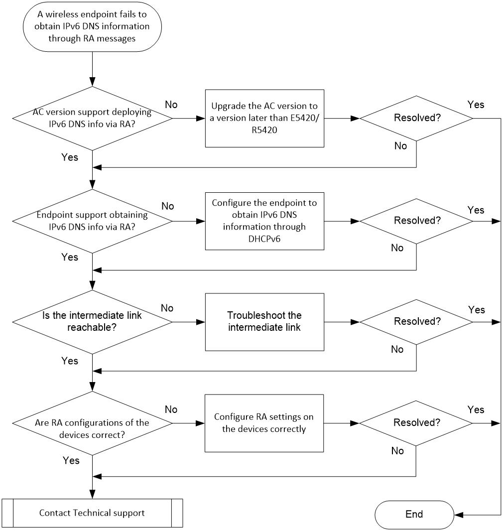
Solution
1. Check the software version on the device side.
Only versions later than E5420 or R5420 support deploying IPv6 DNS information through RA messages. If the AC runs an earlier version, endpoints cannot obtain IPv6 DNS information through RA messages.
Execute the display version command in any view on the AC to view version information.
<AC> display version
H3C Comware Software, Version 7.1.064, Release 5457
…
¡If the version of the AC is too low, upgrade the AC version. Access the H3C official website to obtain the image file. For information about upgrading the software, see software upgrade in the fundamentals configuration guide for the AC.
¡If the AC version supports deploying IPv6 DNS information through RA messages, proceed to the next step.
2. View the endpoint type.
|
|
NOTE: Some Android endpoints do not support the single IPv6 protocol stack. Such Android endpoints can obtain DNS-related information only in the hybrid IPv4+IPv6 network environment. |
Windows-based endpoints only support obtaining DNS address information through DHCPv6, and cannot automatically obtain IPv6 DNS information through RA messages.
¡If the wireless endpoint runs a Windows system, configure it to obtain IPv6 DNS information through DHCPv6. For the configuration procedure, see step 4 in "Endpoint failure to automatically obtain an IPv6 address through stateless address configuration."
¡If the wireless endpoint does not run a Windows system, proceed to the next step.
3. Check the VLAN configurations of the devices on the network.
Incorrect VLAN configurations on the devices can cause link failure. As a result, wireless endpoints cannot obtain IPv6 addresses. Forwarding in the wireless network includes local forwarding and centralized forwarding. The VLAN configurations on devices vary by forwarding mode as follows.
¡Centralized forwarding
In centralized forwarding mode, the AP transparently transmits traffic from clients to the AC through the CAPWAP tunnel, and the AC forwards the data packets. In practice, the management VLAN for AP onboarding and the service VLAN for wireless endpoint access are typically configured. Data packets are transmitted to the AC through the management VLAN, and then the AC forwards the data packets through the service VLAN. For the endpoint to obtain an IP address, you must permit the service VLAN on the link along which the AC forwards the data packets.
|
|
NOTE: The service VLANs can be configured in multiple methods in descending order of priority: VLAN authorized by authentication, VLAN bound to a radio interface, and VLAN specified in a service template. |
As shown in Figure 33, the core switch acts as the gateway, the AC is attached to the core switch, and the AP is connected to the access switch. In this case, you must permit service VLAN 200 on the link along which the AC transmits wireless data packets (the AC-Switch1 link).
Figure 33 Configuring VLANs on the centralize forwarding network

¡Local forwarding
In local forwarding mode, wireless endpoints and the AC exchange control packets through the CAPWAP tunnel and the AP forwards data packets. In practice, the management VLAN for AP onboarding and the service VLAN for wireless endpoint access are typically configured. For the endpoint to obtain an IP address, you must permit the service VLAN on the link along which the AC forwards the data packets.
|
|
NOTE: The service VLANs can be configured in multiple methods in descending order of priority: VLAN authorized by authentication, VLAN bound to a radio interface, and VLAN specified in a service template. |
As shown in Figure 34, the core switch acts as the gateway, the AC is attached to the core switch, and the AP is connected to the access switch. Permit service VLAN 200 on the link along which the AP forwards wireless data packets (the Switch1-Switch2-AP link).
Figure 34 Configuring the AC on the local forwarding network
Execute the display current-configuration command in any view on the devices to view all VLAN configurations.
¡If the VLAN configurations of the devices on the network are incorrect, troubleshoot the VLAN configurations as described in the preceding information.
¡If VLAN configurations of the devices on the network are correct, proceed to the next step.
4. Check interface configurations of the devices on the network.
Incorrect physical interface configurations might cause failure to permit VLANs. The correct interface configurations are as follows.
¡Centralized forwarding
In the network as shown in Figure 33, configure the physical interfaces GE 1/0/1 and GE 1/0/2 of the link between the AC and the gateway Switch1 as trunk ports and configure them to permit service VLAN 200.
¡Local forwarding
In the network as shown in Figure 34, assign the physical interface connecting the AP to the uplink device to the VLAN for client onboarding. You can configure the AP either by editing the MAP file on the AC or remotely configuring the AP. This section uses the MAP file configuration method as an example.
If a wireless endpoint comes online in VLAN 200, you must assign interface GigabitEthernet 1/0/1 connecting the AP to the switch to VLAN 200. The contents of the MAP file are as follows:
|
|
NOTE: Write the commands to be executed in sequence into the apcfg.txt file (a text file), and upload the file to the AC. After the AC is associated with the AP, deploy the configuration to the AP by using the map-configuration command. This completes the configuration of the AP. |
# apcfg.txt configuration file:
system-view
vlan 200
quit
interface GigabitEthernet 1/0/1
port link-type trunk
port trunk permit vlan 200
Configure the downlink interface of gateway Switch1 and the downlink and uplink physical interfaces of Switch2 as trunk ports, and assign them to VLAN 200. Configure the PVID as 100 for interface GE 1/0/2 connecting Switch2 to AP.
Execute the display current-configuration command in any view on the devices to view all interface configurations.
¡If the interface configurations of the devices on the network are incorrect, troubleshoot the interface configurations as described in the preceding information.
¡If interface configurations of the devices on the network are correct, proceed to the next step.
5. Check the RA configurations on the device.
Incorrect RA configurations on the device might cause wireless endpoints to fail to obtain IPv6 DNS information through RA messages. Typically, the gateway switch is used to send RA messages. Take the following configuration as an example:
¡Comware 7/9-based devices:
<Switch> system-view
[Switch] interface Vlan-interface2
[Switch-Vlan-interface2] ipv6 address 2001::1/64 //Configure the IPv6 address and prefix length of the interface
[Switch-Vlan-interface2] ipv6 nd ra dns server 2001::2 100000 sequence 1 //Configure the DNS server information
[Switch-Vlan-interface2] undo ipv6 nd ra halt //Enable the interface to send IPv6 ND RA messages
¡Comware 5-based devices:
<Switch> system-view
[Switch] ipv6 //On a Comware 5-based switch, enable IPv6 globally. On a Comware 7-based switch, IPv6 has been enabled globally by default, and you do not need to execute this command
[Switch] interface Vlan-interface2
[Switch-Vlan-interface2] ipv6 address 2001::1/64 //Configure the IPv6 address and prefix length of the interface
[Switch-Vlan-interface2] ipv6 nd ra dns server 2001::2 100000 sequence 1 //Configure the DNS server information
[Switch-Vlan-interface2] undo ipv6 nd ra halt //Enable the interface to send IPv6 ND RA messages
Execute the display current-configuration command in any view on the device to view its complete configuration.
¡If the RA configuration on the device is incorrect, modify the configuration as shown in the example.
¡If the RA configuration on the device is correct, proceed to the next step.
6. If the issue persists, collect the following information, and contact Technical Support:
¡To narrow down the troubleshooting scope, capture packets on the incoming/outgoing interfaces of the AC or on the wireless endpoint to view the RS/RA message interaction process between the endpoint and AC and identify the phase that causes the failure.
Identify whether the endpoint has sent RS messages.
A router solicitation (RS) message is a multicast message sent by the host to request an immediate RA message without waiting for the next scheduled time. In the IP header, the source address is either the sender interface IPv6 address or all zeros. The destination address is the multicast address FF02::2 for all routers within the link-local scope. An RS message is an ICMP message. It can be filtered by using the icmpv6 keyword in the packet capture software such as Wireshark.
Identify whether the AC responds with RA messages to the endpoint.
The router sends router advertisement (RA) messages periodically to advertise its existence and configured link and network parameters (including DNS information) or respond to RS messages. In the IP header, the source address is the link-local address of the sender interface, and the destination address is the multicast address FF02::1 for all nodes. An RA message is also an ICMP message. It can be filtered in Wireshark by using the icmpv6 keyword.
Identify whether the Option 25 attribute is carried in the RA messages and whether it includes the DNS server address information.
¡Results of each step.
¡The configuration file, log messages, and alarm messages.
Endpoint failure to automatically obtain IPv6 DNS information through DHCPv6
Symptom
An endpoint fails to automatically obtain IPv6 DNS information through DHCPv6. Dynamic Host Configuration Protocol for IPv6 (DHCPv6) is designed for IPv6 addressing schemes. It is used for allocating IPv6 prefixes, IPv6 addresses, and other network configuration parameters, including DNS server address. Its working mechanism is similar to the DHCP protocol in IPv4 networks, and is also known as stateful address configuration.
Possible reasons
The common reasons of this issue include the following:
· Android endpoints do not support automatically obtaining IPv6 DNS information through DHCPv6.
· The VLAN configuration of devices in the network is incorrect, causing Layer 2 network disconnection and failure of the endpoint to obtain IPv6 DNS information.
· Incorrect interface configuration of network devices leads to Layer 2 network disconnection, preventing the endpoint from obtaining IPv6 DNS information.
· Device-side DHCPv6 configuration error leads to endpoint failure to obtain IPv6 DNS information.
· A DHCPv6 message exchange issue occurs between the wireless endpoint and device, causing failure of the endpoint to obtain IPv6 DNS information.
Analysis
Figure 35 shows the diagnostic process of this type of fault.
Figure 35 Problem analysis flowchart
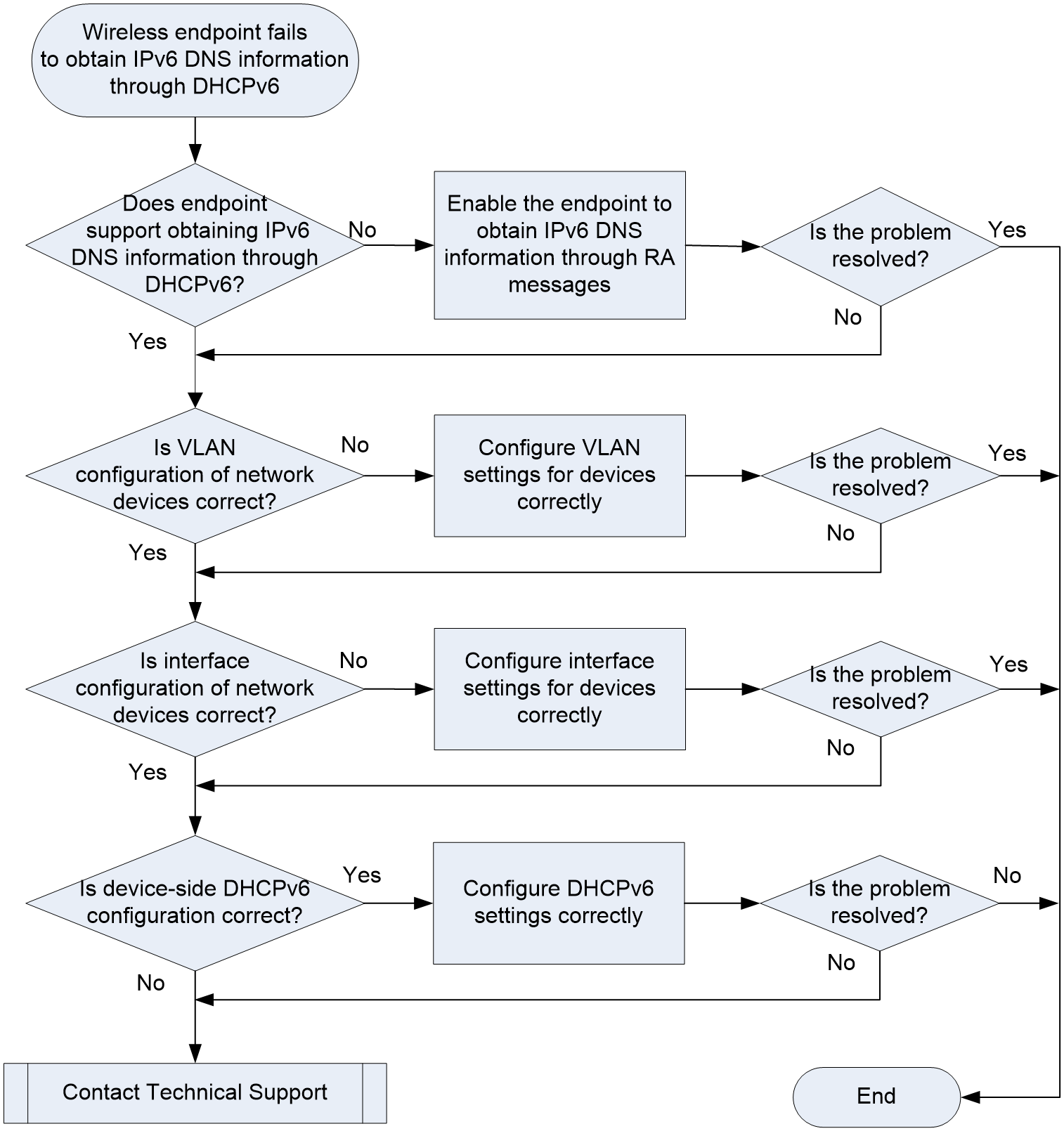
Solution
1. View the endpoint type.
Android endpoints support obtaining DNS address information only through RA, and do not support automatically obtaining IPv6 DNS information through DHCPv6.
¡If the wireless endpoint uses Android system, configure it to obtain IPv6 DNS information through RA messages. For more information, see fundamentals configuration guide in the configuration guides for the device.
¡If the wireless endpoint does not use Android system, proceed to step 2.
2. Check the VLAN configuration of devices in the network.
Incorrect VLAN configuration on the device can cause a disconnection in the intermediate link, resulting in failure of the wireless endpoint to obtain an IPv6 address. Wireless networks support local forwarding and centralized forwarding modes with different VLAN configurations on devices. The specific configuration principles are as follows.
¡Centralized forwarding:
In centralized forwarding mode, the client's data traffic is transmitted through the CAPWAP tunnel by the AP to the AC, and the AC forwards the data packets. Typically, the management VLAN for AP onboarding and the service VLAN for wireless endpoint access are available. Data packets are sent to the AC through the management VLAN and then forwarded to the service VLAN. For the endpoint to obtain an IP address, you need to allow the service VLAN to pass through the link where the AC forwards service packets.
|
|
NOTE: A service VLAN can be configured in multiple ways. Authentication and authorization VLAN has the highest priority. The VLAN bound to radio interface has lower priority. The VLAN specified in the service template has the lowest priority. |
As shown in Figure 36, the core switch acts as the gateway. The AC is connected to the core switch and the AP is connected to the access switch. You need to permit VLAN 200 on the AC-Switch1 link where the AC forwards wireless service packets.
Figure 36 VLAN configuration in centralized forwarding mode

¡Local forwarding:
In the local forwarding mode, the wireless endpoint and AC exchange control packets through the CAPWAP tunnel, and data packets are forwarded by the AP. Typically, the management VLAN for AP onboarding is different the service VLAN for wireless endpoint access. You need to permit the service VLAN on the link where the AP forwards service packets. Without the configuration, the endpoint cannot obtain an IP address.
|
|
NOTE: A service VLAN can be configured in multiple ways. Authentication and authorization VLAN has the highest priority. The VLAN bound to radio interface has lower priority. The VLAN specified in the service template has the lowest priority. |
As shown in Figure 37, the core switch acts as the gateway. The AC is connected to the core switch and the AP is connected to the access switch. You need to permit VLAN 200 on the Switch1-Switch2-AP link where the AP forwards wireless service packets.
Figure 37 AC configuration in local forwarding mode

Execute the display current-configuration command in any view to display configuration of all VLANs.
¡If the VLAN configuration of a device in the network is incorrect, see the previous sections to troubleshoot the VLAN configuration.
¡If the VLAN configuration of the devices in the network is correct, proceed to step 3.
3. Check the interface configuration of devices in the network.
Incorrect physical interface configuration might cause failure to permit VLANs. The correct interface configuration is as follows.
¡Centralized forwarding:
As shown in Figure 36, specify the trunk mode for physical interfaces GE1/0/1 and GE1/0/2 attached to the link between the AC and Switch1, and allow service VLAN 200 to pass through.
¡Local forwarding:
As shown in Figure 37, assign the physical interface of the AP connected to the upstream device to the VLAN for client onboarding. You can perform deployment to the AP through a predefined MAP file edited on the AC or using remote configuration. This chapter describes the MAP file method.
If a wireless endpoint comes online in VLAN 200, assign interface GigabitEthernet 1/0/1 connecting the AP to the switch to VLAN 200. The contents of the MAP file are as follows:
|
|
NOTE: Edit a text file named apcfg.txt in the order of command line configuration and upload it to the AC. After the AC is associated with the AP, use the map-configuration command to deploy it to the AP to complete AP configuration. |
# The configuration file for apcfg.txt is:
system-view
vlan 200
quit
interface GigabitEthernet 1/0/1
port link-type trunk
port trunk permit vlan 200
In addition, specify the trunk mode for the downlink interface of gateway Switch1 and the uplink and downlink interfaces of access switch Switch2, and assign the interfaces to VLAN 200. Set the PVID of interface GE1/0/2 connecting Switch2 and AP to 100.
Execute the display current-configuration command in any view to view configuration of all VLANs.
¡If the interface configuration of a device in the network is incorrect, see the previous sections to troubleshoot the interface configuration.
¡If the interface configuration of the devices in the network is correct, proceed to step 4.
4. Check DHCPv6 configuration on the device side.
Incorrect DHCPv6 configuration on the device side can cause wireless endpoint failure to obtain IPv6 DNS information through DHCPv6. Typically, use the gateway that acts as route advertisement device. The following is a configuration example.
¡Comware 7/9-based devices:
<Switch> system-view
[Switch]IPv6 dhcp pool ipv6
[Switch-dhcp6-pool-ipv6] network 2001::/64
[Switch-dhcp6-pool-ipv6] gateway-list 2001::1
[Switch-dhcp6-pool-ipv6] dns-server 2001::2 //Configure an IPv6 DNS server address
[Switch-dhcp6-pool-ipv6] quit
[Switch] interface Vlan-interface2
[Switch-Vlan-interface2] ipv6 nd autoconfig other-flag //Set the O flag to 1 in RA advertisements to be sent
[Switch-Vlan-interface2] undo ipv6 nd ra halt //Disable RA message suppression
[Switch-Vlan-interface2] ipv6 dhcp select server
[Switch-Vlan-interface2] ipv6 dhcp server apply pool ipv6 //Apply the configured address pool to the interface
¡Comware 5-based devices:
<Switch> system-view
[Switch] ipv6 //Required on Comware V5 devices. IPv6 is enabled globally on Comware V7 devices by default.
[Switch]ipv6 dhcp server enable //Required on Comware V5 devices, and not required on Comware V7 devices.
[Switch]IPv6 dhcp pool ipv6
[Switch-dhcp6-pool-ipv6] network 2001::/64
[Switch-dhcp6-pool-ipv6] gateway-list 2001::1
[Switch-dhcp6-pool-ipv6] dns-server 2001::2 //Configure an IPv6 DNS server address
[Switch-dhcp6-pool-ipv6] quit
[Switch] interface Vlan-interface2
[Switch-Vlan-interface2] ipv6 nd autoconfig other-flag //Set the O flag to 1 in RA advertisements to be sent
[Switch-Vlan-interface2] undo ipv6 nd ra halt //Disable RA message suppression
[Switch-Vlan-interface2] ipv6 dhcp server apply pool ipv6 //Apply the configured address pool to the interface
Execute the display current-configuration command any view to display all device configuration.
¡If the DHCPv6 configuration on the device side is incorrect, edit the configuration. For more information, see the configuration example.
¡If the DHCPv6 configuration on the device side is correct, proceed to step 5.
5. If the issue persists, collect the following information, and contact Technical Support:
¡ Capture messages in the AC input and output directions or on the wireless endpoint side to observe the DHCPv6 message exchange process between the endpoint and AC. Identify the faulty link to narrow down the troubleshooting scope.
You can perform filtering by using keyword DHCPv6 in the packet capture software (using Wireshark as an example). The following example illustrates packet capture for a complete DHCPv6 message exchange process.
Solicit message: The DHCPv6 client sends a Solicit message to determine the location of the DHCP server.
Figure 38 Captured Solicit message
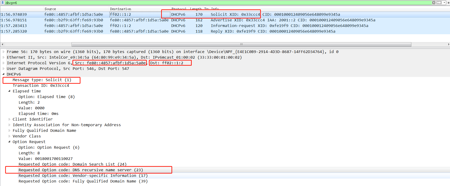
Advertise message: The DHCPv6 server sends an Advertise message in response, declaring its ability to provide DHCPv6 services and carrying DNS information.
Request message: The DHCPv6 client requests IPv6 DNS configuration information from the DHCPv6 server.
Figure 39 Captured Request message
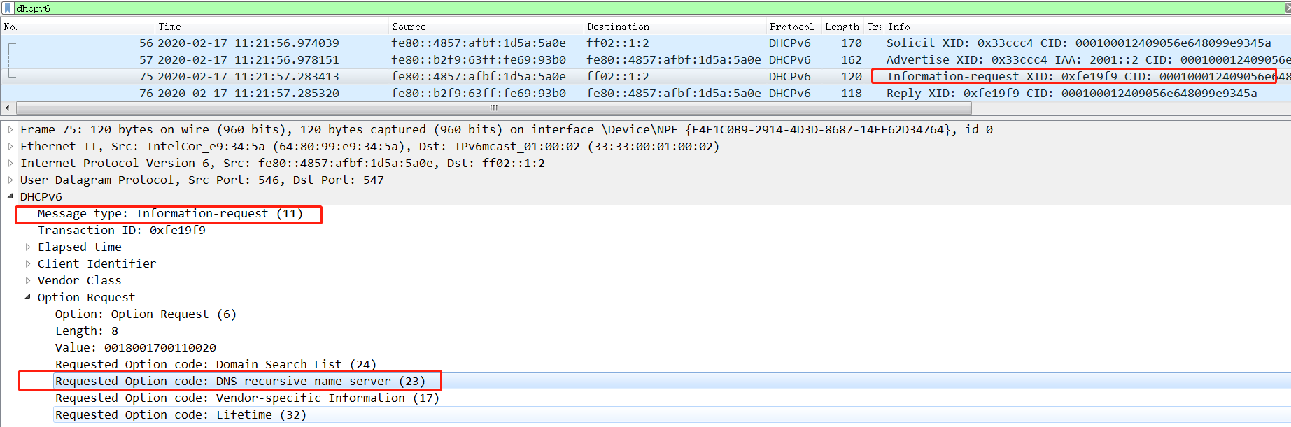
Reply message: The DHCPv6 server sends a Reply message containing configuration information (including DNS information) in response to a Solicit or Request message received from the DHCPv6 client.
¡Execution results of the previous steps.
¡Device configuration files, log information, and alarm information.
Endpoint failure to automatically obtain an IPv6 address through stateless address configuration
Symptom
The endpoint fails to automatically obtain an IPv6 address through RA. Stateless address configuration refers to the automatic configuration of IPv6 address and related information on a host based on its link-layer address and router-advertised prefix information.
Possible reasons
The common reasons of this issue include the following:
· The VLAN configuration of devices in the network is incorrect, causing network disconnection and failure of the endpoint to obtain an IPv6 address.
· Incorrect interface configuration of network devices leads to Layer 2 network disconnection, preventing the endpoint from obtaining an IPv6 address.
· Incorrect stateless address configuration on the device side causes the endpoint to fail to automatically obtain an IPv6 address.
· The route prefix is not 64 bits, causing the endpoint to fail to automatically generate an IPv6 address.
· The Android device does not support obtaining an IPv6 address through stateless address configuration in a pure IPv6 network.
· An RS/RA message exchange issue occurs between the wireless endpoint and device, causing failure of the endpoint to obtain an IPv6 address.
Analysis
Figure 40 shows the diagnostic process of this type of fault.
Figure 40 Problem analysis flowchart
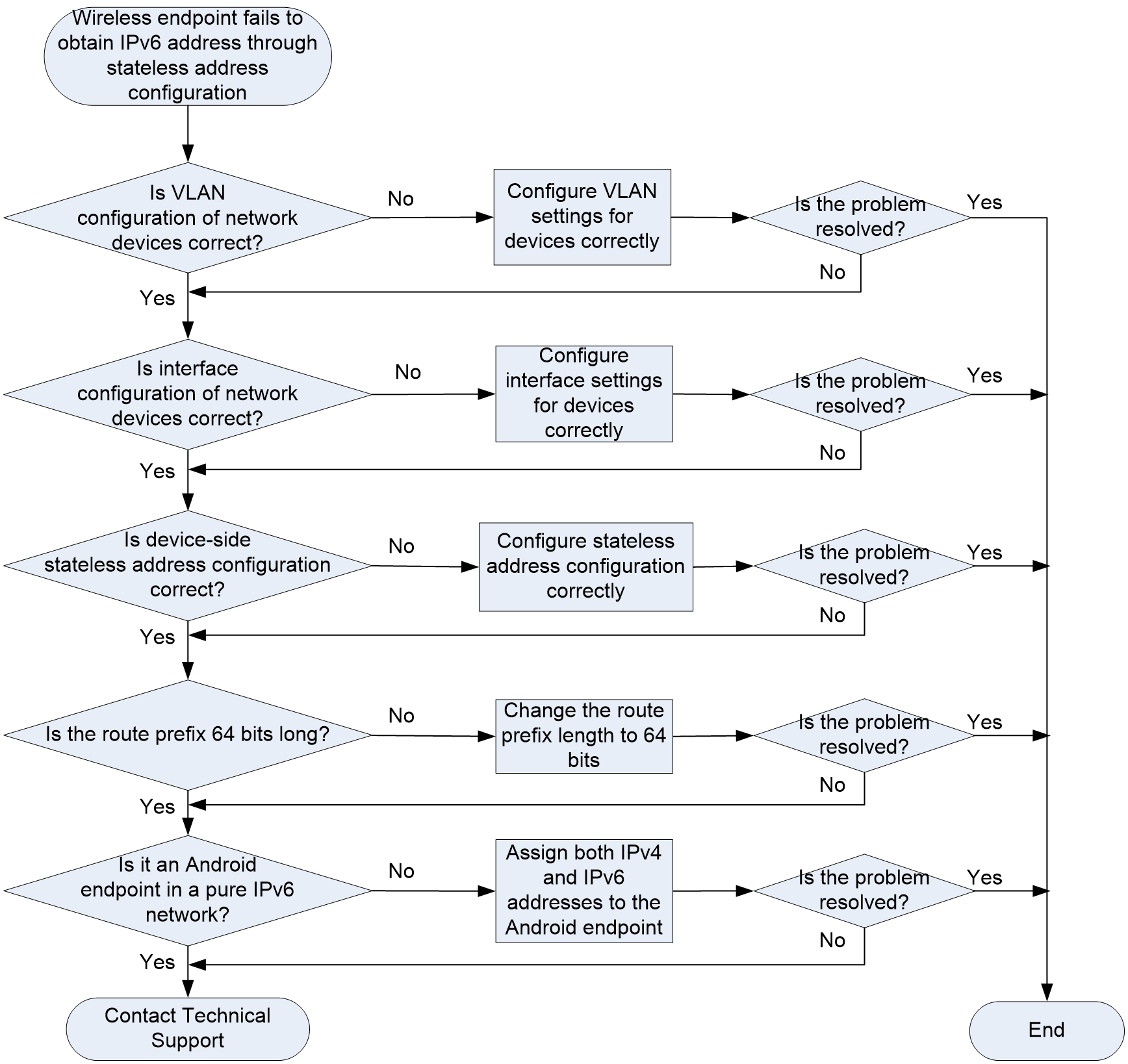
Solution
1. Check the VLAN configuration of devices in the network.
Incorrect VLAN configuration on the device can cause a disconnection in the intermediate link, resulting in failure of the wireless endpoint to obtain an IPv6 address. Wireless networks support local forwarding and centralized forwarding modes with different VLAN configurations on devices. The specific configuration principles are as follows.
¡Centralized forwarding:
In centralized forwarding mode, the client's data traffic is transmitted through the CAPWAP tunnel by the AP to the AC, and the AC forwards the data packets. Typically, the management VLAN for AP onboarding and the service VLAN for wireless endpoint access are available. Data packets are sent to the AC through the management VLAN and then forwarded to the service VLAN. For the endpoint to obtain an IP address, you need to the service VLAN to pass through the link where the AC forwards service packets.
|
|
NOTE: A service VLAN can be configured in multiple ways. Authentication and authorization VLAN has the highest priority. The VLAN bound to radio interface has lower priority. The VLAN specified in the service template has the lowest priority. |
As shown in Figure 41, the core switch acts as the gateway. The AC is connected to the core switch and the AP is connected to the access switch. You need to permit VLAN 200 on the AC-Switch1 link where the AC forwards wireless service packets.
Figure 41 VLAN configuration in centralized forwarding mode

¡Local forwarding:
In the local forwarding mode, the wireless endpoint and AC exchange control packets through the CAPWAP tunnel, and data packets are forwarded by the AP. Typically, the management VLAN for AP onboarding is different the service VLAN for wireless endpoint access. You need to permit the service VLAN on the link where the AP forwards service packets. Without the configuration, the endpoint cannot obtain an IP address.
|
|
NOTE: A service VLAN can be configured in multiple ways. Authentication and authorization VLAN has the highest priority. The VLAN bound to radio interface has lower priority. The VLAN specified in the service template has the lowest priority. |
As shown in Figure 42, the core switch acts as the gateway. The AC is connected to the core switch and the AP is connected to the access switch. You need to permit VLAN 200 on the Switch1-Switch2-AP link where the AP forwards wireless service packets.
Figure 42 AC configuration in local forwarding mode

Execute the display current-configuration command in any view to view configuration of all VLANs.
¡If the VLAN configuration of a device in the network is incorrect, see the previous sections to troubleshoot the VLAN configuration.
¡If the VLAN configuration of the devices in the network is correct, proceed to step 3.
2. Check the interface configuration of devices in the network.
Incorrect interface configuration on the device can cause a disconnection in the intermediate link, resulting in failure of the wireless endpoint to obtain an IPv6 address. Wireless networks support local forwarding and centralized forwarding modes with different interface configurations on devices. The specific configuration principles are as follows.
¡Centralized forwarding:
As shown in Figure 41, specify the trunk mode for physical interfaces GE1/0/1 and GE1/0/2 attached to the link between the AC and Switch1, and allow service VLAN 200 to pass through.
¡Local forwarding:
As shown in Figure 42, assign the physical interface of the AP connected to the upstream device to the VLAN for client onboarding. You can perform deployment to the AP through a predefined MAP file edited on the AC or using remote configuration. This chapter describes the MAP file method.
If a wireless endpoint comes online in VLAN 200, assign interface GigabitEthernet 1/0/1 connecting the AP to the switch to VLAN 200. The contents of the MAP file are as follows:
|
|
NOTE: Edit a text file named apcfg.txt in the order of command line configuration and upload it to the AC. After the AC is associated with the AP, use the map-configuration command to deploy it to the AP to complete AP configuration. |
# The configuration file for apcfg.txt is:
system-view
vlan 200
quit
interface GigabitEthernet 1/0/1
port link-type trunk
port trunk permit vlan 200
In addition, specify the trunk mode for the downlink interface of gateway Switch1 and the uplink and downlink interfaces of access switch Switch2, and assign the interfaces to VLAN 200. Set the PVID of interface GE1/0/2 connecting Switch2 and AP to 100.
Execute the display current-configuration command in any view to view configuration of all VLANs.
¡If the interface configuration of a device in the network is incorrect, see the previous sections to troubleshoot the interface configuration.
¡If the interface configuration of the devices in the network is correct, proceed to step 4.
3. Check RA configuration on the device side.
Incorrect RA configuration on the device side can cause wireless endpoint failure to obtain an IPv6 address through RA. Typically, use the switch gateway that acts as route advertisement device. The correct configuration is as follows.
¡Comware 7/9-based devices:
<Switch> system-view
[Switch] interface Vlan-interface2
[Switch-Vlan-interface2] ipv6 address 2001::1/64 //Configure an IPv6 address and its prefix length for the device interface
[Switch-Vlan-interface2] undo ipv6 nd ra halt //Disable RA message suppression
¡Comware 5-based devices:
<Switch> system-view
[Switch] ipv6 //Required on Comware V5 devices. IPv6 is enabled globally on Comware V7 devices by default.
[Switch] interface Vlan-interface2
[Switch-Vlan-interface2] ipv6 address 2001::1/64 //Configure an IPv6 address and its prefix length for the device interface
[Switch-Vlan-interface2] undo ipv6 nd ra halt //Disable RA message suppression
Execute the display current-configuration command any view to display all device configuration.
¡If the RA configuration on the device side is incorrect, edit the configuration. For more information, see the configuration example.
¡If the RA configuration on the device side is correct, proceed to the next step.
4. Check the route prefix.
The prefix carried in the RA message must be 64 bits long for the endpoint to automatically obtain an IPv6 address. By default, the prefix used by the RA message is the IPv6 address prefix of the message forwarding interface. Use the display ipv6 interface prefix command on the device forwarding the message to check if the IPv6 address prefix on the forwarding interface is 64 bits long.
# View IPv6 prefix information for VLAN-interface 10.
<Sysname> display ipv6 interface Vlan-interface 10 prefix
Prefix: 1001::/64 Origin: ADDRESS
Age: - Flag: AL
Lifetime(Valid/Preferred): 2592000/604800
Prefix: 2001::/64 Origin: STATIC
Age: - Flag: L
Lifetime(Valid/Preferred): 3000/2000
Prefix: 3001::/64 Origin: RA
Age: 600 Flag: A
Lifetime(Valid/Preferred): -
¡If the IPv6 address prefix of the forwarding interface is not 64 bits long, you can manually modify the prefix length by using the ipv6 address command or configure the prefix length in the RA message by using the ipv6 nd ra prefix command.
¡If the IPv6 address prefix of the forwarding interface is 64 bits long, proceed to the next step.
5. View the endpoint type.
The Android endpoint does not support IPv6 single protocol stack. The Android endpoint can obtain an IPv6 address only when it has obtained an IPv4 address in a network with both IPv4 and IPv6 configured.
If the Windows/IOS endpoint in the network can obtain an IPv6 address through stateless address configuration correctly, but the Android endpoint cannot, edit the network plan to assign an IPv4 address to the Android endpoint.
¡If the Android endpoint resides in a pure IPv6 network, edit the network plan.
¡If the network is configured with both IPv4 and IPv6, proceed to the next step.
6. If the issue persists, collect the following information, and contact Technical Support:
¡Capture messages in the AC input and output directions or on the wireless endpoint side to observe the RS/RA message exchange process between the endpoint and AC. Identify the faulty link to narrow down the troubleshooting scope.
Check if the endpoint has initiated an RS message to request routing information.
The RS message is sent by the host side in multicast to request quick advertisement from the router. It requires the router to immediately generate a router advertisement message without waiting for the next scheduled time. The source address in the IP portion is either the IPv6 address of the sending interface or an all-zero address. The destination address is multicast address FF02::2 for all routers in the link-local scope. RS messages are ICMP messages, which can be filtered in Wireshark by using the icmpv6 keyword.
Check if the AC has responded to the router advertisement (RA). The router periodically sends RA messages to advertise the configured link and network parameters, or responds to router requests. The source address in the IP portion is the link-local address of the sending interface. The destination address is multicast address FF02::1 for all nodes. RA messages are also ICMP messages, and they can be filtered in the packet capture software (such as Wireshark) by using the icmpv6 keyword.
Check if the M bit in the Flag field of the RA message is set to zero. When the M bit (Managed Address Configuration Flag) is set, automatic address configuration is performed by using a stateful, manageable protocol. Otherwise, only stateless automatic address configuration is used. The flag M is set to zero by default. If it is not set to zero, an error exists in the configuration of the device-side routing information. You need to check the device-side configuration.
¡Execution results of the previous steps.
¡ Device configuration files, log information, and alarm information.
Stateful address configuration fails for clients
Symptom
Clients failed to obtain IPv6 addresses automatically through DHCPv6. Dynamic Host Configuration Protocol for IPv6 (DHCPv6) is designed for IPv6 addressing. It allocates IPv6 prefixes, addresses, and other parameters to hosts, which is similar to DHCP in IPv4 and is also known as stateful address configuration.
Possible reasons
The common reasons of this issue include the following:
· Android endpoints do not support using stateful address configuration to obtain IPv6 addresses.
· The interface and VLAN configurations on network devices are incorrect, which causes Layer 2 connectivity errors.
· The stateful address configuration is incorrect on the device.
· Errors occur during the DHCPv6 message interaction process between wireless clients and devices.
Analysis
Figure 43 shows the fault diagnosis flowchart.
Figure 43 Problem analysis flowchart
Solution
1. View the client type.
Android endpoints support only the stateless address configuration method and cannot obtain IPv6 addresses through stateful address configuration.
¡If the wireless clients run on Android, configure stateless address configuration. For more information, see step 3 in the solution of "Endpoint failure to automatically obtain an IPv6 address through stateless address configuration."
¡If the wireless clients do not run on Android, proceed to step 2.
2. Verify that VLAN settings on network devices are configured correctly.
Incorrect VLAN configuration on devices can cause link errors and prevent wireless clients from obtaining an IPv6 address. The required VLAN configuration varies by WLAN forwarding method.
¡In centralized forwarding:
In centralized forwarding mode, APs pass client data traffic through CAPWAP tunnels to the AC, and the AC forwards the traffic. In practice, a management VLAN is configured for the APs to go online and a service VLAN is configured for access of wireless clients exist. Packets are transmitted through the management VLAN to the AC, and the AC forwards packets through the service VLAN. To make sure clients can obtain IP addresses, you must configure the forwarding link to allow the service VLAN to pass.
|
|
NOTE: The system can use the authorized VLAN, VLAN bound to the radio interface, VLAN specified for the service template as the service VLAN and the priorities of these VLANs are in descending order. |
As shown in Figure 44, the core switch operates as the gateway with the AC attached. The AP is connected to the access switch. Link AC-Switch 1 forwards wireless packets. You must configure the link to allow VLAN 200 to pass.
Figure 44 VLAN configuration for centralized forwarding

¡In local forwarding:
In local forwarding mode, wireless clients and the AC exchange control packets through CAPWAP tunnels and the APs forward the traffic. In practice, a management VLAN is usually configured for APs to go online and a service VLAN is usually configured for access of wireless clients. To make sure clients can obtain IP addresses, you must configure the forwarding link to allow the service VLAN to pass.
|
|
NOTE: The system can use the authorized VLAN, VLAN bound to the radio interface, VLAN specified for the service template as the service VLAN and the priorities of these VLANs are in descending order. |
As shown in Figure 45, the core switch operates as the gateway with the AC attached. The AP is connected to the access switch. Link Switch 1-Switch 2-AP forwards wireless packets. You must configure the link to allow VLAN 200 to pass.
Figure 45 AC configuration for local forwarding

To view all VLAN configurations, execute the display current-configuration command in any view.
¡If the VLAN settings of network devices are configured incorrectly, troubleshoot VLAN configuration as previously described.
¡If the VLAN settings of network devices are configured correctly, proceed to step 3.
3. Verify that interface settings on network devices are configured correctly.
Incorrect physical interface configuration might cause VLAN connection errors. Configure the interfaces as follows:
¡In centralized forwarding:
As shown in Figure 44, set the link type of GE 1/0/1 on the AC and GE 1/0/2 on Switch 1 to trunk, and configure the two interfaces to allow VLAN 200 to pass.
¡In local forwarding:
As shown in Figure 45, assign the physical interfaces between the AP and the uplink device to the VLAN where the clients go online. You can either use a pre-configured MAP file on the AC to deploy the configuration to the AP or remotely configure the AP. This chapter takes the MAP file as an example.
To make sure the wireless client can go online in VLAN 200, you must assign GE 1/0/1 on the AP to VLAN 200. The MAP file is as follows:
|
|
NOTE: Prepare a txt file named apcfg.txt in the order of command configuration, and upload the file to the AC. After the AP is associated with the AC, use the map-configuration command on the AC to deploy the configuration in the file to the AP. |
# Configuration file apcfg.txt:
system-view
vlan 200
quit
interface GigabitEthernet 1/0/1
port link-type trunk
port trunk permit vlan 200
Set the link type to trunk for the downlink physical interface of Switch 1, uplink and downlink interfaces on Switch 2. Configure these interfaces to allow VLAN 200 to pass. Set the PVID as 100 for GE 1/0/2 on Switch 2.
To view all VLAN configurations, execute the display current-configuration command in any view.
¡If the interface settings of network devices are configured incorrectly, troubleshoot interface configuration as previously described.
¡If the interface settings of network devices are configured correctly, proceed to step 4.
4. Verify that the stateful address configuration on the device is correct.
If the stateful address configuration on the device is incorrect, wireless clients cannot obtain IPv6 addresses through DHCPv6. The gateway switch is usually the device to advertise routes. Configure the device as follows:
¡For Comware 7 and 9 devices:
<Switch> system-view
[Switch] IPv6 dhcp pool ipv6
[Switch-dhcp6-pool-ipv6] network 2001::/64
[Switch-dhcp6-pool-ipv6] gateway-list 2001::1
[Switch-dhcp6-pool-ipv6] dns-list 2001::2
[Switch-dhcp6-pool-ipv6] quit
[Switch] interface Vlan-interface2
[Switch-Vlan-interface2] ipv6 address 2001::1/64 //Configure the IPv6 address and prefix length for the interface.
[Switch-Vlan-interface2] ipv6 ipv6 nd ra prefix 2001::/64 2592000 604800 no-autoconfig //Specify the prefix not to be used for stateless address configuration. Optional.
[Switch-Vlan-interface2] ipv6 nd autoconfig other-flag //Set the other stateful configuration flag (O) to 1 in RA advertisements.
[Switch-Vlan-interface2] ipv6 nd autoconfig managed-address-flag //Set the managed address configuration flag (M) to 1 in RA advertisements.
[Switch-Vlan-interface2] ipv6 dhcp server allow-hint rapid-commit //Optional.
[Switch-Vlan-interface2] undo ipv6 nd ra halt //Disable RA message suppression.
[Switch-Vlan-interface2] ipv6 dhcp select server
[Switch-Vlan-interface2] ipv6 dhcp server apply pool ipv6 //Apply address pool ipv6 to VLAN-interface 2.
¡For Comware 5 devices:
<Switch> system-view
[Switch]ipv6 //Enable IPv6 globally. By default for Comware v7 devices, IPv6 is enabled.
[Switch]ipv6 dhcp server enable //Enable the DHCPv6 server. You do not need to enable the DHCPv6 server for Comware v7 devices.
[Switch]IPv6 dhcp pool ipv6
[Switch-dhcp6-pool-ipv6]network 2001::/64
[Switch-dhcp6-pool-ipv6]gateway-list 2001::1
[Switch-dhcp6-pool-ipv6]dns-list 2001::2
[Switch] interface Vlan-interface2
[Switch-Vlan-interface2]ipv6 address 2001::1/64 //Configure the IPv6 address and prefix length for the interface.
[Switch-Vlan-interface2] ipv6 ipv6 nd ra prefix 2001::/64 2592000 604800 no-autoconfig //Specify the prefix not to be used for stateless address configuration. Optional.
[Switch-Vlan-interface2] ipv6 nd autoconfig other-flag //Set the other stateful configuration flag (O) to 1 in RA advertisements. required
[Switch-Vlan-interface2] ipv6 nd autoconfig managed-address-flag //Set the managed address configuration flag (M) to 1 in RA advertisements.
[Switch-Vlan-interface2] ipv6 dhcp server allow-hint rapid-commit //Optional.
[Switch-Vlan-interface2] undo ipv6 nd ra halt //Disable RA message suppression.
[Switch-Vlan-interface2] ipv6 dhcp server apply pool ipv6 //Apply address pool ipv6 to VLAN-interface 2.
To display all configurations on a device, execute the display current-configuration command in any view.
¡If the stateful address configuration is incorrect on the device, edit the configuration as previously described.
¡If the stateful address configuration is correct on the device, proceed to step 5.
5. If the issue persists, collect the following information, and contact Technical Support:
¡ To narrow down the troubleshooting scope, capture DHCPv6 messages on the inbound and outbound interfaces of the AC or on the wireless clients. By doing this, you can identify which step of the DHCPv6 message exchange the fault occurs in.
You can use keyword DHCPv6 for filtering in a packet capture software (taking Wireshark as an example). Captured messages in the DHCPv6 message exchange process are as follows:
Solicit message: The DHCPv6 client uses the Solicit message to determine the location of the DHCP server on the network.
Advertise message: The DHCPv6 server responds with an Advertise message, declaring its ability to provide DHCPv6 service. The Advertise message contains DNS information.
Request message: The DHCPv6 client sends a Request message to the DHCPv6 server for IPv6 DNS configuration information.
Reply message: The DHCPv6 server sends a Reply message to assign configuration (including DNS information) to the client.
¡Execute the debugging ipv6 dhcp server event all command on the AC and collect debugging information. Identify whether the DHCPv6 message exchange process is complete between the AC and the client based on the DHCPv6 messages transmitted and received through the packet forwarding interface. The following is a normal DHCPv6 message exchange process that was debugged on the device.
*Nov 14 09:59:14:487 2019 AC DHCPS6/7/EVENT: Received Solicit from FE80::1C1C:1E22:907A:9654.
*Nov 14 09:59:14:487 2019 AC DHCPS6/7/PACKET:
From FE80::1C1C:1E22:907A:9654 port 546, interface Vlan-interface82
Message type: Solicit (1)
Transaction ID: 0x00484796
*Nov 14 09:59:14:488 2019 AC DHCPS6/7/EVENT: Send Advertise to FE80::1C1C:1E22:907A:9654.
*Nov 14 09:59:14:488 2019 AC DHCPS6/7/PACKET:
To FE80::1C1C:1E22:907A:9654 port 8706, interface Vlan-interface82
Message type: Advertise (2)
Transaction ID: 0x00484796
*Nov 14 09:59:15:466 2019 AC DHCPS6/7/EVENT: Received Request from FE80::1C1C:1E22:907A:9654.
*Nov 14 09:59:15:466 2019 AC DHCPS6/7/PACKET:
From FE80::1C1C:1E22:907A:9654 port 546, interface Vlan-interface82
Message type: Request (3)
Transaction ID: 0x000ddf2e
*Nov 14 09:59:15:466 2019 AC DHCPS6/7/EVENT: Send Reply to FE80::1C1C:1E22:907A:9654.
*Nov 14 09:59:15:466 2019 AC DHCPS6/7/PACKET:
To FE80::1C1C:1E22:907A:9654 port 8706, interface Vlan-interface82
Message type: Reply (7)
Transaction ID: 0x000ddf2e
¡Results of previous steps.
¡The configuration file, log messages, and alarm messages.
Slow wireless rate under testing
Symptom
The wireless rate is slow under testing.
Possible reasons
The common reasons of this issue include the following:
· The wired link has a low throughput.
· The wireless network deployment is inappropriate.
· The link connectivity and latency status are abnormal.
· The wireless configuration is not optimal.
· The wireless rate is limited by the client capability.
· The wireless rate is limited by the wireless communication settings.
Analysis
Figure 46 shows the fault diagnosis flowchart.
Figure 46 Problem analysis flowchart

Solution
1. Verify the wired link has sufficient throughput.
The wireless network is an extension of the wired network. Before testing the wireless rate, identify whether pings and service operations can be correctly performed on the wired network, and whether the latency and jitter of the wired network are within normal ranges. Wireless rate testing is meaningful only if the wired link is completely normal.
You can use rate testing software to test the rate of the wired link.
2. Identify the structure of wireless network deployment.
Various solutions and products are available for wireless networks. Before testing the wireless rate, identify the products and deployment methods of the current network.
Wireless network deployment mainly has the following structures:
¡AC + fit AP architecture.
¡Fat AP architecture.
¡AC + fit AP architecture with NAT enabled.
The AC + fit AP architecture has the following forwarding modes:
¡Centralized forwarding.
¡Local forwarding.
Understanding your products and deployment method is crucial for subsequent steps.
To view the forwarding mode in the AC + fit AP architecture, perform the following task to display the configuration of the wireless service template on the AC.
# Identify whether the service template is local forwarding on the AC.
[AC] wlan service-template 1
[AC-wlan-st-1] display this
#
wlan service-template 1
ssid XXX
client forwarding-location ap //The location being the AP indicates that the local forwarding mode is applied.
service-template enable
#
return
Generally, wireless throughput and network rate in the local forwarding mode are often better than those in the centralized forwarding mode. Therefore, for scenarios with a large number of online users and in the centralized forwarding mode, switching to the local forwarding mode can improve wireless rate.
3. Verify that continuous ping results are normal on wireless clients.
Identify the link connectivity and latency status between wireless clients and the Internet through continuous pings.
# Ping 114.114.114.114.
C:\AA>ping 114.114.114.114 -t
Pinging 114.114.114.114 with 32 bytes of data:
Reply from 114.114.114.114: Bytes=32 time=10ms TTL=253
Reply from 114.114.114.114: Bytes=32 time=11ms TTL=253
Reply from 114.114.114.114: Bytes=32 time=11ms TTL=253
Reply from 114.114.114.114: Bytes=32 time=12ms TTL=253
……
Normal latency and low packet loss are prerequisites for good wireless network quality. If packet loss and latency are high, you must troubleshoot the issues.
4. Optimize the wireless configuration.
After checking the connectivity and latency with pings, if you can identify that the issue is caused by the wireless link, optimize the wireless configuration based on the actual situation.
Generally, most office scenarios require specific optimization. For more information about optimization, see H3C WLAN Products Deployment and Maintenance Guide. The core goal is to reduce wireless air interface utilization and improve client negotiation speed.
# View the radios ChannelBusy information on the AP. Generally, make sure the value is lower than 20% for the 2.4 GHz band with no service throughput, and lower than 10% for the 5.8 GHz band with not service throughput. Additionally, the sum of the RxBusy and TxBusy values cannot differ from the CtlBusy value by more than 10. Otherwise, non-WLAN interference might exist. The displayed information is as follows:
[AP-probe] display ar5drv 1 channelbusy
ChannelBusy information
Ctl Channel: 36
BandWidth: 1
Record Interval(s): 9
CurrentTime: 23:55:45
Time(h/m/s): CtlBusy(%) TxBusy(%) RxBusy(%)
01 23:55:43 26 0 25
02 23:55:34 29 0 29
03 23:55:25 31 0 31
04 23:55:16 30 0 29
For ACs with FPGA hardware forwarding modules, you can also enable the hardware fast forwarding feature to accelerate the processing of packets in the centralized forwarding mode.
# Enable hardware fast forwarding on the AC.
[AC] wlan fast-forwarding enable
5. Verify that the client capability is sufficient.
After performing wireless optimization, if the wireless rate is still slow, identify whether the client capability is sufficient. Different clients have different air interface negotiation capabilities. The negotiation capability of a client determines its maximum rate in the wireless network and preemption ability of resources in multi-user concurrency scenarios.
¡Generally, most laptops have 2×2 wireless NICs. If a laptop support the 802.11ac standard, its highest negotiation rate is 866.7 Mbps. The actual maximum throughput is around 600 Mbps because wireless communication is implemented in half duplex mode. However, considering the integrated usage and interference, most clients might operate at 350 Mbps to 400 Mbps.
¡Transmission efficiency also varies by transmitting tool. A high throughput can be tested by using IxChariot. However, if you use ordinary FTP tools or rate testing software, the testing result might be 200 Mbps to 300 Mbps after excluding the cost.
¡Additionally, the actual throughput might differ from the theoretical rate due to uplink rate limits of the outbound network and the home network.
¡Most mobile phones and smart devices with 1×1 wireless NICs might only implement half of the theoretical wireless rate.
For more information, see the tables on MCS rates in the product configuration guide. For example:
Table 8 VHT-MCS rates (80MHz, 2NSS)
|
VHT-MCS index |
Number of spatial streams |
Modulation mode |
Rate (Mb/s) |
|
|
800ns GI |
400ns GI |
|||
|
0 |
2 |
BPSK |
58.5 |
65.0 |
|
1 |
2 |
QPSK |
117.0 |
130.0 |
|
2 |
2 |
QPSK |
175.5 |
195.0 |
|
3 |
2 |
16-QAM |
234.0 |
260.0 |
|
4 |
2 |
16-QAM |
351.0 |
390.0 |
|
5 |
2 |
64-QAM |
468.0 |
520.0 |
|
6 |
2 |
64-QAM |
526.5 |
585.0 |
|
7 |
2 |
64-QAM |
585.0 |
650.0 |
|
8 |
2 |
256-QAM |
702.0 |
780.0 |
|
9 |
2 |
256-QAM |
780.0 |
866.7 |
6. Verify the wireless communication settings are appropriate.
In actual wireless environments, an AP is usually connected with multiple clients, forming a concurrency trend. Since wireless resources are shared and limited, the throughput of the same client and AP device entry might be different in heavy-load and light-load scenarios. If possible, try to maintain a light-load deployment.
If it is difficult to balance the client usage density and the number of deployed APs, limit the wireless rate for each user. This can ensure that one or several users do not occupy a great amount of air interface resources.
You can also reduce the bandwidth for the 5 GHz band, which is 80 MHz by default in an 802.11ac environment. You can adjust the bandwidth to 40 MHz or 20 MHz to increase available non-overlapping channels. The maximum negotiation rate of each channel will decrease.
7. If the issue persists, contact Technical Support.
Troubleshooting device startup
This section provides troubleshooting information for common device startup issues.
Garbled characters or no output at device startup
Symptom
Garbled characters are displayed or no output is displayed on the terminal screen while the device is starting up.
Solution
To resolve the issue:
1. Verify that the serial port speed setting for the device and the login software are the same.
2. Remove the memory module, clean the connectors, and re-install the memory module.
If the device does not support removing memory modules, contact Technical Support to resolve the issue.
3. Access the BootWare menu, press Ctrl+U , and then enter 1 to perform a RAM test.
¡ If the system prompts BootWare basic segment damage, see "System startup failure" to resolve the issue.
¡ If the system prompts memory module damage, contact Technical Support to replace the memory module.
===========================<BASIC-ASSISTANT MENU>===========================
|<1> RAM Test |
|<0> Exit To Main Menu |
============================================================================
Enter your choice(0-1): 1
Warning:Test Memory will take a long time? [Y/N]Y
Memory test.....................
509607936 bytes memory test ok.
Memory test succeeded.
4. If the issue persists, contact Technical Support.
System startup failure
Symptom
The device cannot start up.
Solution
Device startup failures usually occur during a pilot deployment or after a software upgrade.
To resolve the issue:
1. Power cycle the device and observe the output information.
If the System image is starting... message is displayed, contact Technical Support.
If the System image is starting... message is not displayed, the device has failed to load the BootWare. Possible BootWare load failure reasons include the following:
¡ The BootWare is damaged.
- If the device does not display any information at startup or displays garbled characters, the basic BootWare segment is damaged. Contact Technical Support to burn the BootWare.
- If the basic BootWare menu is displayed, the extended BootWare segment is damaged. Use the BootWare image file to update the BootWare.
¡ The startup software images are corrupt or moved.
To resolve the issue, access the extended BootWare menu to specify or download new startup software images.
¡ The file system is corrupt.
To resolve the issue, format the file system and download the software images again.
2. If the issue persists, contact Technical Support.
AP reboot for unknown reason
Symptom
An AP reboots unexpectedly or reboots repeatedly. You cannot locate the reboot reason.
Possible reasons
The common reasons of this issue include the following:
· Device power recycling.
· Manual reboot.
· Software reboot.
Analysis
Resolve the issue according to the reboot reason. For this purpose, you must first locate the reboot reason.
· If the reboot reason is device power recycling, check the cables for connectivity issues and check the power supply device for power supply exceptions.
· For manual reboot, check the following items:
¡ Whether the RESET button has been pressed.
¡ Whether the AP has been manually rebooted through the CLI, SNMP, or Web interface.
¡ Whether the AP has not been registered with the AC for a long time.
· For software reboot, the possible reasons include kernel exception, memory leakage, watchdog reboot, and version auto upgrade.
Solution
Use one of the following methods to locate the reboot reason:
· On the AC, execute the display wlan ap name ap-name verbose command to display detailed AP information and check the Last reboot reason field for the reboot reason.
<Sysname> display wlan ap name ap1 verbose
AP name : ap1
AP ID : 1
AP group name : default-group
State : Run
Backup type : Master
Online time : 0 days 1 hours 25 minutes 12 seconds
System uptime : 0 days 2 hours 22 minutes 12 seconds
Model : WA6320
Region code : CN
Region code lock : Disable
Serial ID : 219801A28N819CE0002T
MAC address : 0AFB-423B-893C
IP address : 192.168.1.50
UDP control port number : 18313
UDP data port number : N/A
H/W version : Ver.C
S/W version : E2321
Boot version : 1.01
...
Sent control packets : 1
Received control packets : 1
Echo requests : 147
Lost echo responses : 0
Average echo delay : 3
Last reboot reason : User soft reboot
Last reboot reason (AP check) : The radio physical status was down
Last reboot reason (AC check) : The radio physical status was down
...
· Log in to the AP through the console port, and execute the diag boot-info display command in probe view to display the reboot time and reason for the most recent 10 reboots.
<Sysname>system-view
System View: return to User View with Ctrl+Z.
[Sysname]probe
[Sysname-probe]diag boot-info display
******************************************************************************
PowerOn BootTimes : 19
Watchdog BootTimes : 0
Software BootTimes : 262
Hardware BootTimes : 1
MotherBoard BootTimes: 0
Backup BootTimes : 0
SlotOut BootTimes : 0
Current Boot Type : Hardware-boot
Current Running Time: 120(s)
Running Time : 83(d)0(h)
*** Boot History(Startup Time and Reason) ***
2022-07-11 02:05:19(GMT+0) Hard reboot
2022-07-11 02:05:19(GMT+0) Power on
2022-07-11 02:05:19(GMT+0) User soft reboot(Stayed in idle state for a long time)
2022-07-11 01:55:14(GMT+0) User soft reboot(Stayed in idle state for a long time)
2022-07-11 01:45:09(GMT+0) User soft reboot(Stayed in idle state for a long time)
2022-07-11 01:35:04(GMT+0) Power on
2022-07-11 01:35:04(GMT+0) User soft reboot(Stayed in idle state for a long time)
2022-07-11 01:24:59(GMT+0) Power on
2022-07-11 01:24:59(GMT+0) User soft reboot(Stayed in idle state for a long time)
2022-07-11 01:14:54(GMT+0) User soft reboot(Stayed in idle state for a long time)
Table 9 shows the common AP reboot reasons.
Table 9 Common AP reboot reasons
|
Field |
Reboot reason |
Solution |
|
Power on |
The AP is power recycled. |
|
|
Hard reboot |
The AP is rebooted through the RESET button. |
See "Manual reboot." |
|
User soft reboot |
· The AP is rebooted through the CLI, SNMP, or Web interface. · The AP has not been registered with the AC for a long time. |
|
|
Watchdog reboot |
Watchdog reboot. |
See "Software reboot." |
|
Unknown reboot |
Unknown reason. |
|
|
Kernel exception soft reboot |
Kernel exceptions. |
|
|
Kernel deadloop soft reboot |
Kernel deadloops. |
|
|
Auto update soft reboot |
Version auto upgrade. |
|
|
Unknown soft reboot |
Unknown software reason. |
|
|
Memory exhausted |
The memory is exhausted. |
|
|
Other unknown soft reboot |
Other reasons. |
Reboot caused by device power recycling
Symptom
Execute the display wlan ap name ap-name verbose command on the AC, or log in to the AP and execute the diag boot-info display command in probe view. In the command output, the reboot reason is Power on.
Possible reasons
If the AP is powered by a PoE switch, the issue might be caused by one of the following reasons:
· The network cable does not meet the power supply requirements.
· The PoE switch reboots.
· Poweroff upon overload is triggered on the PoE switch.
If the AP is powered by a power adapter or PoE injector, the issue might be caused by one of the following reasons:
· The power supply device does not meet the power supply requirements.
· The power supply device is damaged.
Analysis
Figure 47 and Figure 48 show the diagnostic process of this type of fault.
Figure 47 Problem analysis flowchart (PoE)
Figure 48 Problem analysis flowchart (power adapter or PoE injector)
Solution
To resolve the issue when the AP is powered by PoE:
1. Check the network cable situation:
a. Verify that the network cable meets the specification requirements.
Make sure the cable is a Category 5E (or above) cable. For a 2.5/5GE interface, you must use a Category 5E (or above) cable. For a 10GE interface, you must use a Category 6 (or above) cable.
- If the cable does not meet the requirements, replace it with another cable that meets the requirements.
- If the cable meets the requirements, go to the next step.
b. Verify that the network cable is not damaged.
Verify that the RJ connector connected to the AP is not loose. You can use a new cable to replace the original cable and observe for a period of time to see whether the AP still restarts.
- If the issue is resolved, the original cable is damaged. In this case, you can replace the original cable with a new cable.
- If the issue persists after the cable replacement, go to the next step.
c. Verify that the PoE power supply distance does not exceed the reliable power supply distance.
As a best practice, the distance between a PSE and a PD is shorter than 90 meters and cannot exceed 100 meters at maximum. If the distance exceeds the reliable power supply distance, shorten the distance between the PSE and PD or use another power supply method.
2. Check the PoE switch:
a. On the PoE switch, execute the display version command to view the uptime of the switch to identify whether the switch has rebooted.
<Sysname> display version
H3C Comware Software, Version 7.1.070, Feature 2607
Copyright (c) 2004-2017 New H3C Technologies Co., Ltd. All rights reserved.
H3C XXX uptime is 0 weeks, 0 days, 2 hours, 14 minutes
Last reboot reason : Cold reboot
Boot image: flash:/XXX-cmw710-boot-f2607.bin
...
By comparing the uptime of the switch and the uptime of the AP, you can determine whether the AP reboot is caused by the switch reboot. If the switch uptime and AP uptime are close, the AP reboot might be caused by the switch reboot.
b. Check whether poweroff upon overload has been triggered.
IEEE has successively released 802.3af (PoE), 802.3at (PoE+), and 802.3bt (PoE++) PoE standards, with later standards being backward compatible with earlier ones.
Table 10 Power supply technologies
|
Power supply technology |
PoE |
PoE+ |
PoE++ |
|
Standard compliance |
IEEE802.3af |
IEEE802.3at |
IEEE802.3bt |
|
PSE output power |
≤ 15.4 W |
≤ 30 W |
≤ 90 W |
|
PD maximum power |
12.95 W |
25.5 W |
71.3 W |
|
Cable requirements |
N/A |
Higher than Category 5E |
Higher than Category 5E |
Visit the H3C official website to get the installation guide for the AP and obtain information about the standard followed by the powered port on the AP and the total power consumption of the AP.
- If the total power consumption of the AP does not exceed 12.95 W, a PoE-capable switch can meet the power supply requirements.
- If the total power consumption of the AP is greater than 12.95 W but less than or equal to 25.5 W, you can use a PoE+ switch or a power injector to supply power for the AP.
- If the total power consumption of the AP is greater than 25.5 W, you can use a PoE++ switch or a PoE injector that can provide external power of up to 60 W to supply power for the AP.
In scenarios where the AP and PoE switch follow the IEEE802.3af standard to perform negotiation, the maximum power output per single port of the switch is 15.4 W. However, in situations where a large number of access users exist, the actual power consumption of the AP might exceed 15.4 W. This can trigger the overload protection mechanism on the switch, resulting in poweroff. You can attempt to increase the maximum power of the PI by using the poe max-power max-power command.
|
|
NOTE: The maximum power of PI interfaces varies by device model. |
3. If the issue persists, contact Technical Support.
To resolve the issue if the AP is powered by a power adaptor or PoE injector:
4. Verify that the power supply device meets the specification requirements.
Verify that the output power (voltage and current) of the power adapter or PoE injector meets the voltage requirements specified in the AP installation guide.
- If the output power does not meet the requirements, replace the power adapter or PoE injector with a compatible power adapter or PoE injector.
- If the output power meets the requirements, go to the next step.
5. Verify that the power supply device is not damaged.
Perform a cross test by replacing the existing power adapter or PoE injector with another one of the same model. If the issue is resolved, failure exists on the original power supply device. In this case, you must replace the original power supply device with a new power supply device.
6. If the issue persists, contact Technical Support.
Manual reboot
Symptom
Execute the display wlan ap name ap-name verbose command on the AC, or log in to the AP and execute the diag boot-info display command in probe view. In the command output, the reboot reason is Hard reboot or User soft reboot.
Possible reasons
The common reasons of this issue include the following:
· The RESET button on the AP is pressed.
· The reboot configuration is manually deployed to the AP.
· The periodic reboot feature is configured.
· The AP in fit mode is not associated with the AC.
Analysis
Figure 49 shows the diagnostic process of this type of fault.
Figure 49 Problem analysis flowchart
Solution
1. Check whether the RESET button has been pressed.
If the reboot reason is Hard reboot, the RESET button has been pressed.
Figure 50 RESET button
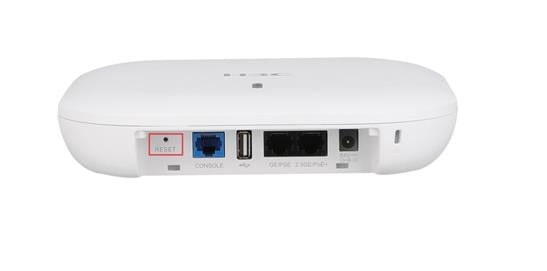
2. Check whether the AP has been manually rebooted through configuration:
To resolve the issue if the reboot reason is User soft reboot:
a. Check whether the reboot configuration has been manually deployed to the AP.
Check whether someone has rebooted the AP through the CLI, SNMP, or Web interface before the AP rebooted, and obtain the operations that have been performed. If no one has rebooted the AP, go to the next step.
b. Execute the display scheduler job and display scheduler schedule commands to check whether the scheduled reboot feature is configured for the AP.
The following shows an example to describe how to configure scheduled reboot for the AP when the AP operates in fit mode:
# On the AC, configure AP ap1 to reboot at 21:00 every Saturday.
[Sysname] scheduler job resetap
[Sysname-job-resetap] command 1 reset wlan ap name ap1
[Sysname-job-resetap] quit
[Sysname] scheduler schedule resetap
[Sysname-schedule-resetap] job resetap
[Sysname-schedule-resetap] time repeating at 21:00 week-day Sat
# Display job configuration.
[Sysname] display scheduler job
Job name: resetsp
reset wlan ap name ap1
# Display schedule information.
[Sysname] display scheduler schedule
Schedule name : resetap
Schedule type : Run on every Sat at 21:00:00
Start time : Sat Jul 16 21:00:00 2022
Last execution time : Sat Jul 16 21:00:00 2022
Last completion time : Sat Jul 16 21:00:15 2022
Execution counts : 1
-----------------------------------------------------------------------
Job name Last execution status
resetap Successful
c. Verify that the AP is associated with the AC when it operates in fit mode.
If the AP is not associated with the AC when it operates in fit mode, it will reboot periodically (typically, at intervals of 7 to 8 minutes). To check whether the AP is associated with the AC, use the display wlan ap name ap-name command and view the State field.
<Sysname> display wlan ap name ap1
AP information
State : I = Idle, J = Join, JA = JoinAck, IL = ImageLoad
C = Config, DC = DataCheck, R = Run M = Master, B = Backup
AP name APID State Model Serial ID
ap1 1 I WA6320 219801A28N819CE0002T
If the AP is not associated with the AC, use the display wlan ap name ap-name verbose command and check the Tunnel down reason field for the CAPWAP tunnel disconnection reason. For more information about the reasons, see AP Management Command Reference.
<Sysname> display wlan ap name ap1 verbose
AP name : ap1
AP ID : 1
AP group name : default-group
State : Run
Backup type : Master
Online time : 0 days 1 hours 25 minutes 12 seconds
System uptime : 0 days 2 hours 22 minutes 12 seconds
Model : WA6320
Region code : CN
...
Last reboot reason (AP check) : The radio physical status was down
Last reboot reason (AC check) : The radio physical status was down
Latest IP address : 10.1.0.2
Current AC IP : 192.168.1.1
Tunnel down reason : Request wait timer expired
...
3. If the issue persists, contact Technical Support.
Software reboot
Symptom
Execute the display wlan ap name ap-name verbose command on the AC, or log in to the AP and execute the diag boot-info display command in probe view. In the command output, the device displays one of the following reboot reasons:
· Watchdog reboot.
· Unknown reboot.
· Kernel exception soft reboot.
· Kernel deadloop soft reboot.
· Auto update soft reboot.
· Unknown soft reboot.
· Memory exhausted.
· Other unknown soft reboot.
Possible reasons
The possible reasons for software reboot include kernel exception, memory leakage, watchdog reboot, and version auto upgrade. Unknown reboot reasons, for example, CPU exception, are also classified as software reboot reasons.
Analysis
As a best practice to resolve this issue, read the release notes for the product and upgrade the software to the latest version.
Solution
To resolve the issue:
1. Upgrade software for the AP.
Read the resolved problems and open problems in the release notes for the reboot issue. If the reboot issue is added to the list of resolved problems in a version, you can upgrade the software to that version.
2. If the issue persists, contact Technical Support.
