- Released At: 08-11-2024
- Page Views:
- Downloads:
- Related Documents
-
H3C Data Center Switches
Green Energy-Efficient Technologies White Paper
Copyright © 2023 New H3C Technologies Co., Ltd. All rights reserved.
No part of this manual may be reproduced or transmitted in any form or by any means without prior written consent of New H3C Technologies Co., Ltd.
Except for the trademarks of New H3C Technologies Co., Ltd., any trademarks that may be mentioned in this document are the property of their respective owners.
The information in this document is subject to change without notice.
Contents
Leakage power reduction techniques
Enhanced transceiver module integration
80 plus certified dual-input power supplies
Automatic fan speed adjustment
Section-based speed adjustment
Overview
Technical background
With the advancement of digital transformation, data centers have developed rapidly, and new-generation information technology such as cloud computing is transforming data centers. However, explosive growth of data is posing new challenges to data centers. High energy consumption has become a bottleneck for data center development.
The emergence of energy-efficient technologies helps to improve energy efficiency. Energy-efficient technologies can be applied in multiple dimensions and multiple layers, which can reduce energy consumption and improve heat dissipation efficiency. It aims at maximizing energy efficiency and minimizing environmental impact.
This document describes energy-efficient features currently used for H3C data center switches.
Benefits
Energy-efficient technologies offer the following benefits:
· Reduced total energy consumption and emissions, and therefore reduced costs through green designs.
· Extension of devices' lifetime by differentiating busy and idle periods.
· AI-driven heat dissipation adjustment, with less manual intervention.
· Convenient, easy, efficient equipment room design.
· Driving green and low-carbon transformation.
EEE
About EEE
Energy efficient Ethernet (EEE) can dynamically adjust the power of copper interfaces based on network traffic. IEEE 802.3az, the standard for EEE, was approved in September, 2010. The standard is designed to reduce energy consumption of a link when the network is idle and restore power supply during when data transmission starts.
Implementation
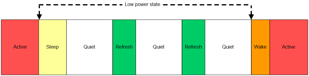
With EEE enabled, a link-up interface enters low power mode if it has not received any packet for a period of time. The physical layer (PHY) chip of the interface is in low power state. When a packet arrives later, the interface restores to normal working mode and the PHY chip exits low power state. EEE takes effect only when the PHY chips on interfaces at both ends support EEE.
Figure 1 EEE workflow
Auto power-down
An interface consumes power even if it does not have traffic. Auto power-down (also called port energy saving), provides a method to utilize power in such a way that an interface uses power only during data transmission.
With auto power-down enabled on an interface, the device automatically stops supplying power to that interface if that interface has been down for a period of time and places that interface in power-saving mode. The time period depends on the chip specifications and is not configurable.
When the interface comes up, the device automatically restores power supply and the interface automatically restores to normal state.
Low power chips
Leakage power reduction techniques
One of the most effective ways to reduce chip energy consumption is upgrading chip techniques. Scaling down of transistors causes larger proportion of leakage power to the total chip energy consumption. As a result, reducing leakage power becomes more and more important.
In geometries smaller than 90nm, leakage power has become the dominant consumer of power. The transistor gate length determines the leakage power of a chip. Shorter transistor gate length indicates less leakage power. The transistor gate length of a chip with advanced techniques changes from 28 nm to 16 nm, and then to 7 nm. The change greatly enhances chip integration and reduces leakage power.
AVS design
The total energy consumption of a chip has a positive correlation with voltage. When frequency requirements are met, lowering voltage can reduce energy consumption. Adaptive voltage scaling (AVS) can obtain the processor performance (frequency) requirements and automatically adjust voltage based on the requirements, which lowers both voltage and total energy consumption of the chip.
Low power transceiver modules
Transceiver modules are used for transmitting optical signals, which consume a large amount of power when receiving and transforming optical signals.
Enhanced transceiver module integration
H3C enhances transceiver module chip integration to reduce energy consumption in the following methods:
· Uses digital signal processors (DSPs) whose transistor gate length is 16 nm or 7 nm. A DSP is the core chip of a transceiver module, which has high energy consumption. Similar to device chips, shorter transistor gate length indicates less energy consumption for DSPs.
· Integrates DSPs with drivers and trans-impedance amplifiers (TIAs).
¡ Driver—Located at the optical transmitter of a transceiver module, converts electrical signals to corresponding modulated signals so that the laser can emit light.
¡ TIA—Located in the front of the photodetector in the transceiver module optical receiver, converts optical signals to electrical signals and pre-amplifies the electrical signals.
In addition, H3C is trying to use uncooled electro-absorption modulated laser (EML) chips for transceiver modules. In the future, H3C might use uncooled EML chips to further reduce energy consumption of transceiver modules.
An EML, widely used for 400G transceiver modules, is a signal transmitting unit. Typically, an EML must cooperate with a thermos-electric cooler (TEC) to lower temperature. However, a TEC consumes a large amount of power. With upgraded chip designs, an uncooled EML can lower temperature independently, which causes less energy consumption.
Low power mode
A transceiver module consumes power even if the fiber port where it is installed does not receive or transmit data.
H3C allows you to set the working mode for 400G transceiver modules. When a transceiver module has been in standby state for a long time, you can switch its working mode to low power mode. In this mode, the transceiver module cannot transmit signals. To have the transceiver module transmit signals, manually switch its working mode to high power mode.
Optimal system link designs
When the link signal quality is satisfied, fewer components indicate less loss. H3C further reduces system energy consumption by performing granular control over PCB cabling loss and using low-loss PCBs instead of lite-PHY chips or retimer chips.
Dynamic power saving
Power supplies can operate in redundancy mode to avoid power failures and overload. When the energy consumption is large or a master power supply is faulty, a standby power supply with the highest priority automatically starts up and supplies power to the device. Based on the power supply load, the switch automatically configures the standby power supplies to work in master/standby mode and cuts off output of the standby power supplies to save power.
80 plus certified dual-input power supplies
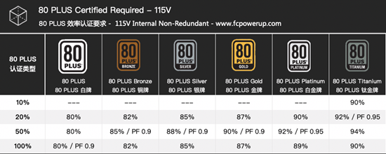
To be 80 plus certified, a power supply must have greater than 80% power efficiency at 20%, 50%, and 100% loads. Power efficiency is the output power divided by the input power. The 80 plus certification aims to increase the power efficiency and power factor value, thereby reducing energy consumption, heat dissipation, room cooling costs, and maintenance costs and improve device availability.
Figure 2 80 plus certificate requirements
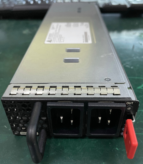
H3C's energy-efficient and environmental-friendly dual-input power supplies certified by 80 plus platinum have high power efficiency and availability and support hot backup.
Figure 3 80 plus certified dual-input power supply
Cooling system
The cooling system is an important part of DCs and is also one of the main sources of energy consumption. To improve energy efficiency of the cooling system, H3C provides sound cooling designs:
· Component-layer designs—Chip or module cooling, thermal conductive material, and heatsink designs.
· Module-layer designs—Heatsink, airflow, and optimized card designs.
· Device-layer designs—Airflow, fan tray, and liquid-cooled switch designs.
Module cooling designs
With rapid development of integrated circuit technology, electronic devices have better performance but smaller sizes, which leads to larger power density. To resolve the issue of high temperature during module operation, H3C adds heatsinks or thermal conductive materials to chips.
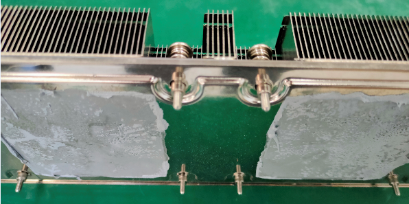
· High-performance thermal conductive pads, phase change materials (PCMs), and silicone grease materials with low thermal resistance for high power chips.
Thermal conductive materials are designed to solve the problem of high heat transfer rate from the chip to the heatsink. By analyzing and testing various thermal materials such as thermal silicone grease, thermal silicone paste, phase change thermal materials, and carbon nanotube thermal materials, H3C continuously tests their thermal performance and production feasibility. In collaboration with third-party professional institutions, H3C conducts experiments to ensure their long-term reliability and establishes a complete high-performance thermal material selection platform for developers to match appropriate thermal materials with different chip cooling requirements.
Figure 4 Thermal conductive silicone grease
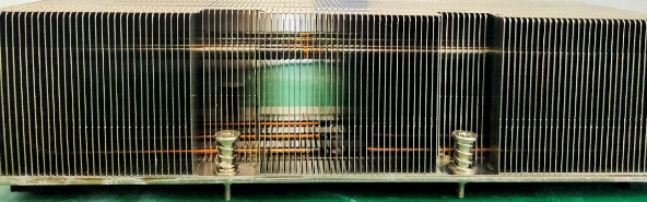
· High-performance heat pipes and vapor chambers (VCs) for high-power chips.
For an air cooling system, heatsinks are the core of the system cooling solution. Cooperating with professional heatsink vendors, H3C develops and verifies high-performance heatsinks such as heat pipes, VCs, and siphon heatsinks. H3C popularizes the commercialization of VCs and also creatively uses shared VCs for multiple chips.
Figure 5 VCs
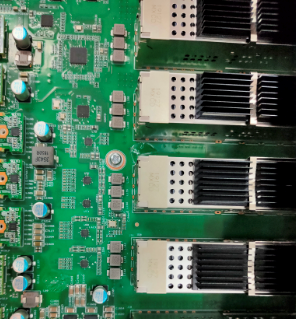
· Cooling cages and heatsinks for high-power transceiver modules.
For example, for a QSFP-DD transceiver module, the typical energy consumption per port is 12 W to 15 W, which is four times as great as that of a 100G transceiver module. For a long-haul transceiver module, the typical energy consumption per port might reach 20 W in the future. This addresses higher requirements for heat dissipation on ports. To resolve such an issue, H3C takes the following measures:
¡ Optimizes the air vent shape and space between air vents in the port-side panel.
¡ Customizes stacked cages with larger spacing between two layers to improve ventilation of transceiver modules at the lower layer.
¡ Enhances the heat dissipation capabilities of PCBs.
Figure 6 Cooling cages for transceiver modules
Automatic fan speed adjustment
PWM-based speed adjustment
About PWM-based speed adjustment
Based on pulse width modulation (PWM), the device can adjust its fan speed automatically based on the temperatures of different components on the device, such as MPUs, service modules, and switching fabric modules. When the device temperature does not exceed the lower limit for fan speed adjustment, the fans operate at a very low speed with little noise and small energy consumption. When the device temperature crosses the upper limit, the fans accelerate automatically for fast heat dissipation.
PWM uses digital outputs of a microprocessor to control analog circuits. At a certain frequency, PWM outputs different voltages based on different duty cycles to adjust the fan speed. Basic elements of PWM are as follows:
· Frequency (f)—How fast the PWM completes a cycle in one second. For example, frequency 50 Hz indicates 50 PWM cycles per second.
· Period (T)—The time from the start of one pulse to the next, in seconds. The calculation formula is T=1/f.
· Width—The time measured across a pulse.
· Duty cycle—The amount of time the signal is in a high state to the total time it takes to complete one cycle, in percentage. For example, if a pulse period is 10 ms and the pulse width is 8 ms, the duty cycle is 80%.
Figure 7 Pulse width and period

PWM can adjust the duty cycle of the output voltage to obtain different analog voltages. As shown in Figure 8, assume that the high voltage level is 5 V and the low voltage level is 0 V. At a certain frequency, if you have 50% duty cycle, the output analog voltage would be 2.5 V. If you have 75% duty cycle, the output analog voltage would be 3.75 V. If you have 20% duty cycle, the output analog voltage would be 1 V.
Figure 8 PWM analog voltage output

Mechanism
All the key chips on the MPUs, service modules, and switching fabric modules can read the junction temperature. The device can adjust the duty cycle of the fan voltage based on the junction temperature to control the fan speed. As shown in Figure 9, within the specified temperature range for fan speed adjustment, the fan speed increases as the device temperature increases.

To lower the fan speed or noise, you can use the fan auto-control-mode command to set the following fan operating modes:
· Balance—Configures the fan to operate in a balanced way. In this mode, the fan speed is lower than the low-temperature mode and higher than the silence mode to provide balanced noise control and cooling performance.
· Low-temperature—Configures the fan to operate at a higher speed to provide better cooling service.
· Silence—Configures the fan to operate at a lower speed to reduce the noise at the cost of lower cooling service quality. This mode applies to noise-sensitive environments.
Section-based speed adjustment
On an H3C switch that supports section-based speed adjustment, each fan is in charge of heat dissipation for a specific section. For example, fan 1 is in charge of slot 0 to slot 3 and fan 2 is in charge of slot 4 to slot 6. The system can adjust the speed of fans for different sections to precisely control the temperature in each section and reduce energy consumption.
AI-based speed adjustment
About AI-based speed adjustment
AI-based fan speed adjustment uses the local AI service component on the switch to optimize fan speed dynamically through certain modeling algorithms. The AI service component arranges the speed of each fan on the device to achieve higher energy efficiency, with the temperature of the device kept in a normal range.
Mechanism
Typically, a switch uses the PID algorithm for device temperature control. The PID algorithm is simple, easy to implement, and can be applied widely, but it has a low regulation accuracy. When the device temperature changes, the PID algorithm requires some time to adjust the fan speed.
AI-based fan speed adjustment uses a set of heuristic search algorithms as the core algorithm. This type of algorithm can calculate the most energy-efficient fan speed based on the current state of the device. To improve stability, the system uses the PID algorithm to adjust the fan speed only when the fans are in initial state or have overtemperature alarms.
Figure 10 AI-based fan speed adjustment
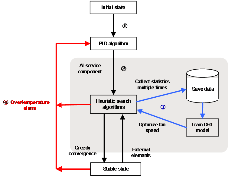
AI-based fan speed adjustment operates as follows:
1. After startup, the device uses the PID algorithm to adjust the fan speed to a stable state and sends the following information to the AI service component regularly:
¡ Voltage and current statistics for each chip, card, and service module, and temperatures of chips and temperature measuring points.
¡ Speed and power consumption statistics for all fans.
¡ Power supply output statistics.
2. After receiving the statistics, the AI service component uses the heuristic search algorithms to correct the speed of each fan in real time, with the temperature of the device kept in a normal range. After calculating the most energy-efficient fan speed, the AI service component deploys the speed to the device.
3. After receiving a large amount of device operation data, the AI service component will train the deep reinforcement learning (DRL) model automatically. When the device temperature, power consumption, or other information changes, the AI service component will use the DRL model to deduce the optimal fan speed in real time. To ensure the optimal fan speed, the AI service component re-trains the DRL model at certain intervals.
4. If an overtemperature alarm occurs during the device operation, the AI service component will switch to the PID algorithm to control the fan speed.
Air-cooled switch design
Air cooling is one of the most common ways to cool electronic devices. In an air cooling system, the design of air aisles determines the cooling effect. An excellent air aisle design can not only save energy, but also reduce the device failure rate.
Card-level air cooling design
To improve cooling efficiency, each card on the device must have clear air ducts that facilitate airflow. H3C's developers fully consider factors such as the heat generated by each component, as well as its size and position when designing the air ducts.
Direct front-to-rear airflow design
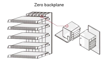
H3C has introduced switches that use an orthogonal direct-connect (OD) system architecture and higher service module slots. The switches can accommodate higher signal rates and achieve greater throughput while addressing the challenges of traditional backplane architecture in size, complexity, scalability, and heat dissipation. With a direct air aisle, greater slot height, and finely tuned air aisle control within modules, the system provides better heat dissipation for the chips.
Figure 11 Traditional PCB backplane architecture
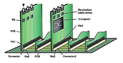
Figure 12 Traditional PCB backplane architecture
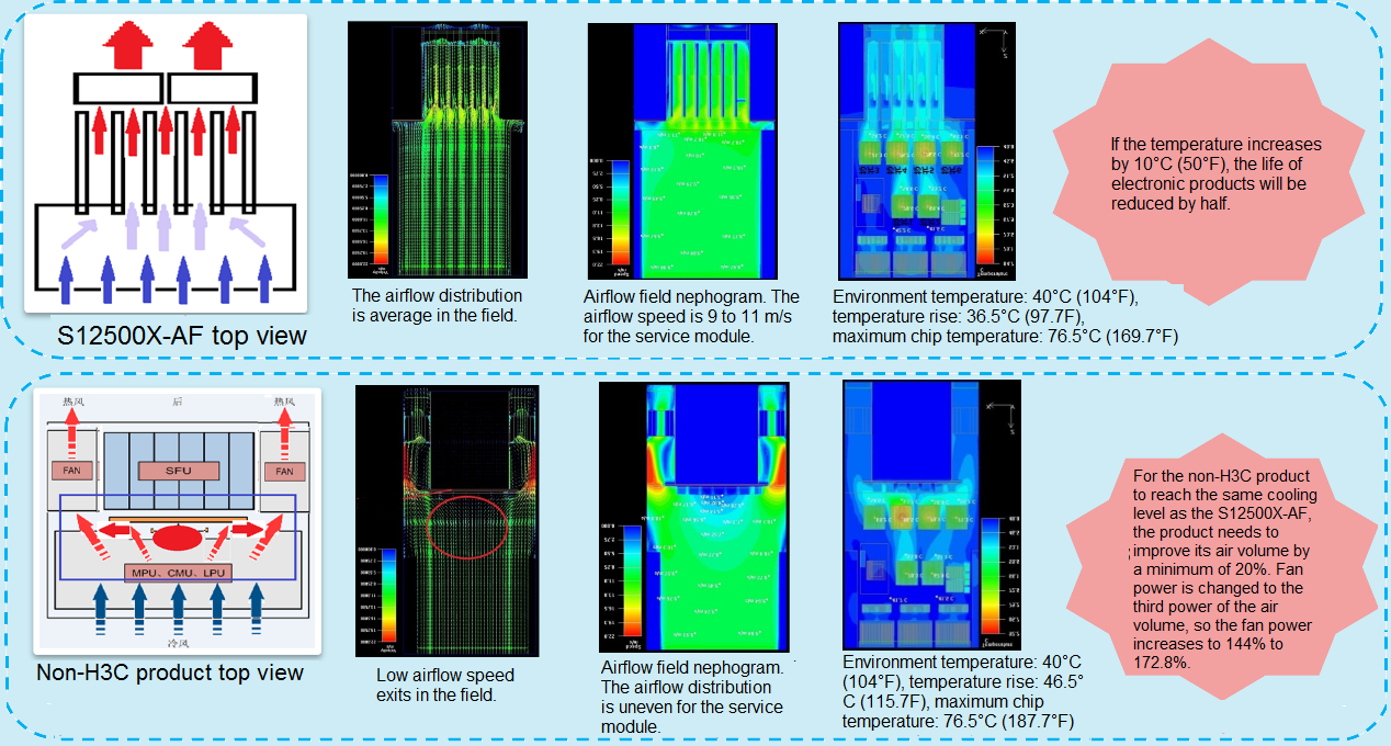
Compared with products from other vendors, H3C's direct front-to-rear airflow design ensures higher cooling efficiency.
Figure 13 Direct front-to-rear airflow
Liquid-cooled switch design
Background
As data centers flourish in the digital economy, chip processing capability and power density are increasing to meet the exponential data growth in data centers. This brings rapid increase of power density per cabinet in data centers and cabinet cooling requirements.
Figure 14 Power per cabinet in the data center
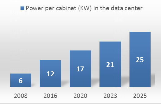
As power per cabinet increases, the existing air cooling system cannot meet the cooling requirements. In the existing air cooling scheme, high cabinet power requires higher fan speeds, larger fan diameters, and wider air aisles. This causes greater noise in equipment rooms and increases the construction, operations, and maintenance costs on equipment rooms. Faced with these issues and stricter energy efficiency constraints, liquid cooling is becoming a key technology to reduce the PUE value of data centers.
Figure 15 Air-cooled and liquid-cooled equipment rooms
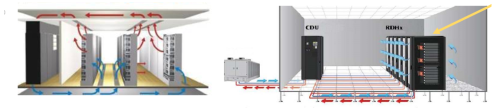
Liquid cooling has higher thermal transfer efficiency than air cooling. It uses liquid convection and heat transfer to lower the temperature of electronic components, preventing component failures or rapid aging under high temperature, and enabling devices to operate with the best performance. Liquid cooling has significant effect on reducing the maximum temperature of devices and improving the consistency of component temperature fields.
Depending on the immersion form, liquid cooling is divided into immersion cooling (direct liquid cooling), cold plate cooling (indirect liquid cooling), and spray cooling. Depending on the state of the coolant, immersion cooling is divided into single-phase cooling and phase-change cooling.
· Single-phase cooling—The coolant always stays in liquid form in the cooling cycles.
· Phase-change cooling—The coolant has phase changes during the cooling. The coolant is vaporized into gas, absorbing the thermal energy around it, and then transferred back to the cabinet.
H3C provides single-phase, immersion cooled switches. A single switch can save up to 40 W power in heat dissipation.
About H3C liquid-cooled switches
H3C provides single-phase, liquid cooled switches with high-density 25G and 100G interfaces. Each switch can save 40 W power in heat dissipation.
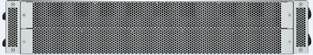
As shown in Figure 16, the switch provides honeycomb openings in the front and rear panels to ensure a bottom-to-top liquid cooling and liquid cooling with the maximum amount of coolant volume.
Figure 16 Front view of a liquid-cooled switch

Figure 17 Rear view of a liquid-cooled switch