- Released At: 21-02-2023
- Page Views:
- Downloads:
- Related Documents
-
|
|
|
H3C Switches |
|
IRF Fabric to M-LAG System Conversion |
|
Configuration Guide |
|
|
Document version: 6W100-20230214
Copyright © 2023 New H3C Technologies Co., Ltd. All rights reserved.
No part of this manual may be reproduced or transmitted in any form or by any means without prior written consent of New H3C Technologies Co., Ltd.
Except for the trademarks of New H3C Technologies Co., Ltd., any trademarks that may be mentioned in this document are the property of their respective owners.
The information in this document is subject to change without notice.
Contents
Checking the dynamic routing settings
Checking inter-member services
Checking the IRF bridge MAC settings
Configuring convergence time optimization
Example: Converting an IRF fabric to an M-LAG system on the underlay network
Network configuration before conversion
Major settings before conversion
Conversion key points and network diagram
Converting the leaf IRF fabric to an M-LAG system
Converting the spine IRF fabric to an M-LAG system
Conversion key points and network diagram
Converting the leaf IRF fabric to an M-LAG system
Converting the spine IRF fabric to an M-LAG system
Network 1 after conversion (the spine devices are connected to DCGW through an aggregate interface)
Network configuration before conversion
Major settings before conversion
Conversion key points and network description
Converting the TOR and EOR IRF subordinate devices from IRF member devices to M-LAG member devices
Converting the operating mode of the EOR IRF subordinate device from IRF mode to standalone mode
Configuring M-LAG settings on the TOR IRF subordinate device
Configuring M-LAG settings on the EOR IRF subordinate device
Verifying the configuration on TOR1-2
Verifying the configuration on EOR1-2
Converting the TOR and EOR IRF master devices from IRF member devices to M-LAG member devices
Converting the operating mode of the EOR IRF master device from IRF mode to standalone mode
Configuring M-LAG settings on the TOR IRF master device
Configuring M-LAG settings on the EOR IRF master device
Verifying the configuration on TOR1-1
Verifying the configuration on EOR1-1
Verifying the configuration on the TOR devices
Verifying the configuration on the EOR devices
Introduction
About IRF
The Intelligent Resilient Framework (IRF) technology virtualizes multiple physical devices at the same layer into one virtual fabric to provide data center class availability and scalability. IRF virtualization technology offers processing power, interaction, unified management, and uninterrupted maintenance of multiple devices.
About M-LAG
Multichassis Link Aggregation (M-LAG) virtualizes two physical devices into one system through multichassis link aggregation to provide device-class high availability and load sharing.
Comparison of IRF and M-LAG
Table 1 shows the characteristics of IRF and M-LAG. As a best practice, use M-LAG in a scenario that requires high availability in networking and short service interruption time for software upgrade.
Table 1 Comparison of IRF and M-LAG
|
Item |
IRF |
M-LAG |
|
Control plane |
All member devices are centrally managed and controlled. All member devices synchronize all entries among them. |
The member devices are decoupled on the control plane as independent devices. The member devices mainly synchronize MAC and ARP entries between each other. |
|
Device plane |
Tightly coupled. Hardware requirements: All member devices must have the same chip architecture, that is, they must be devices from the same series. Software requirements: All member devices must run the same version of software. |
Loosely coupled. Hardware requirements: Devices of different models can set up an M-LAG system. Software requirements: The member devices in an M-LAG system can run different versions of software. However, in the current development stage of M-LAG, some products require that the member devices in an M-LAG system must run the same version of software. |
|
Version upgrade |
All member devices synchronously upgrade software or use a complex method to separately upgrade software for the master and subordinate devices. Services are interrupted for about 2 seconds during software upgrade. |
The member devices in an M-LAG system can independently upgrade software. Services are interrupted for less than 1 second during software upgrade. For versions that support graceful insertion and removal (GIR), you can upgrade software for the member devices without service interruption. For more information about using GIR to upgrade software for M-LAG member devices, see H3C Switches M-LAG System Upgrade & Replacement & Expansion Guide. |
|
Configuration management |
Unified configuration, unified management, and simple operation. Tightly coupled. Single points of failure might occur when the IRF fabric is cooperating with a controller. |
Independent configuration. The M-LAG system performs configuration consistency check to detect configuration conflicts. You must manually ensure that service settings do not conflict on the member devices. Independent management, loose coupling, and high availability. Single points of failure do not exist when the M-LAG system is cooperating with a controller. |
|
|
NOTE: GIR enables you to gracefully isolate a device from the network for device maintenance or upgrade. GIR minimizes service interruption by instructing the affected protocols (for example, routing protocols) to isolate the device and switch over to the redundant path. You do not need to configure graceful switchover protocol by protocol. For more information about GIR, see Fundamentals Configuration Guide. |
Applicable product matrix
|
Scenario |
Hardware series |
Software versions |
|
Data center |
S12500X-AF, S12500G-AF, S12500F-AF |
As a best practice, use the recommended software versions for the switches. For more information about the recommended versions, see H3C Data Center Switches M-LAG Configuration Guide and H3C Campus Switches M-LAG Configuration Guide. |
|
S9820, S9850 |
||
|
S6800, S6812[S6813], S6805, S6825, S6850, S6860, S6890, S6900 |
||
|
Campus |
S12500G-AF, S12500-XS |
|
|
S10500X |
||
|
S7600, S7600E-X, S7500X |
||
|
S6550XE-HI, S6525XE-HI |
Prerequisites
Checking the services
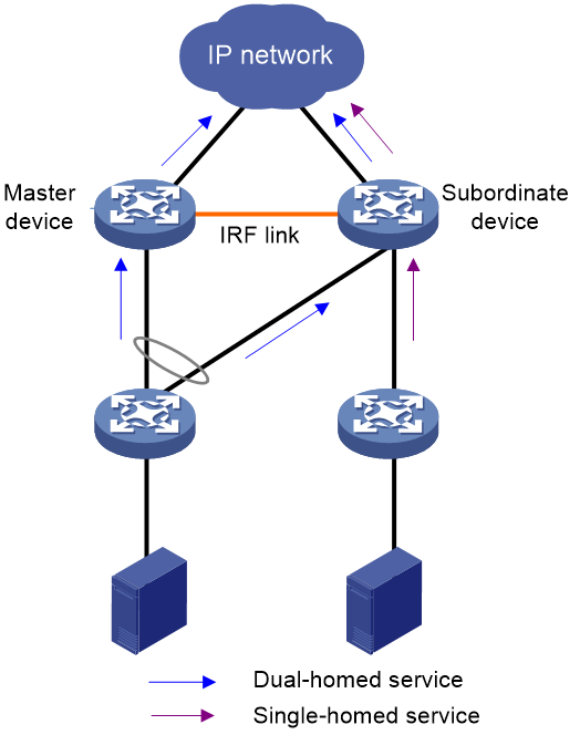
As shown in Figure 1, services are dual-homed or single-homed to the IRF fabric.
· For dual-homed services, you must switch over all the service traffic on one member device to the other member device during the conversion process. Make sure the bandwidth capability of each member device meets the service requirements. If a single member device cannot bear all the service traffic, consider whether to temporarily switch over some of the service traffic to other devices. After the IRF fabric is converted to an M-LAG system, switch over the service traffic back to the M-LAG member devices.
· For single-homed services that are interruption insensitive, you can interrupt the services during the conversion process. After the IRF fabric is converted to an M-LAG system, recover the services.
· For single-homed services that are interruption sensitive, first change single-homed services to dual-homed services. Then, use the method described for dual-homed services to switch over traffic.
Figure 1 Single-homed and dual-homed services
Checking the dynamic routing settings
After an IRF fabric is converted to an M-LAG system, the number of routes between the M-LAG member devices and upstream devices increases. The number of routes on an M-LAG member device might reach the upper limit. As a best practice to reduce the number of routes, configure static routes for communication between the M-LAG member devices and upstream devices.
Checking the ACL resources
M-LAG interfaces consume ACL resources. Make sure the member devices have sufficient ACL resources to ensure successful IRF fabric to M-LAG system conversion. You can view alarm messages to obtain ACL resource usage and adjust available ACL resources accordingly.
Checking inter-member services
If an IRF fabric has multichassis services such as multichassis mirroring and redirection, the multichassis service settings cannot take effect after the IRF fabric is converted to an M-LAG system. You must re-plan traffic forwarding models and modify the multichassis service settings to ensure that the traffic input and output interfaces belong to the same device.
Checking the IRF bridge MAC settings
By default, the bridge MAC address of an IRF fabric is the bridge MAC address of the master device. If the irf mac-address persistent command is used to configure IRF bridge MAC persistence, both the IRF member devices will still use the bridge MAC address of the master device after the IRF fabric splits. If the irf mac-address mac-address command is used to specify a MAC address as the IRF bridge MAC address, both the IRF member devices will still use the specified MAC address as their bridge MAC address after the IRF fabric splits. The two member devices have the same bridge MAC address, which causes network communication issues.
Before you convert an IRF fabric to an M-LAG system, use the undo irf mac-address persistent and undo irf mac-address commands to enable the split IRF fabrics to immediately change their IRF bridge MAC addresses to the bridge MAC addresses of their own master devices.
Configuring convergence time optimization
As a best practice, configure the following settings to ensure fast network convergence for IRF fabric to M-LAG system conversion:
· Exclude the following interfaces from the shutdown action by M-LAG MAD:
¡ Interfaces attached to the keepalive link.
¡ VLAN interfaces of the VLANs to which M-LAG interfaces belong.
¡ Layer 3 interfaces for interconnection between the two M-LAG member devices.
· As a best practice, set the data restoration interval to 300 seconds by using the m-lag restore-delay command. If the size of the ARP or MAC address table is large, you can increase the data restoration interval accordingly. If the size of the ARP table on a modular device is near to 48 K, set the data restoration interval to 900 seconds.
· If the member devices have a large number of MAC address entries, use the mac-address timer aging command to increase the MAC address aging time. As a best practice, set the MAC address aging time to a value larger than 20 minutes.
· First convert the IRF subordinate device to an M-LAG member device and then convert the IRF master device to an M-LAG member device. If you convert the IRF master device to an M-LAG member device before the IRF subordinate device, IRF master/subordinate switchover will occur. Packet loss might occur during the switchover.
Cautions
For a modular device, you must execute the undo chassis convert mode command to convert the device operating mode from IRF to standalone before configuring M-LAG settings. After the mode conversion, the interface indexes have changes, including the indexes of VLAN interfaces, aggregate interfaces, and VSI interfaces. Use this command with caution for applications that are strongly related to interface indexes, for example, the ADNET solution.
For a fixed-port device, deleting IRF settings and configure M-LAG settings do not affect the indexes of existing interfaces. The index of an interface does not change if you do not delete the interface.
Example: Converting an IRF fabric to an M-LAG system on the underlay network
In this example, the typical spine and leaf architecture in data centers is used to illustrate IRF fabric to M-LAG system conversion.
Network configuration before conversion
· The spine and leaf layers each is deployed with an IRF fabric that contains two member devices.
· The server is connected to the leaf IRF member devices through a multichassis aggregate link.
· The leaf IRF member devices are connected to the spine IRF member devices through multichassis aggregate links.
· The spine IRF member devices are connected to DCGW through a multichassis aggregate link.
· The spine IRF fabric acts as the gateway of the server and has static route settings for communication with the external network connected to DCGW.
As the service requirements have changes, perform the following tasks:
· Convert the spine and leaf IRF fabrics to M-LAG systems.
· Convert the multichassis aggregate interfaces connected to the server, leaf devices, spine devices, and DCGW to M-LAG interfaces. The spine devices can be connected to DCGW through an M-LAG interface or a Layer 3 interface and ECMP routes. As a best practice, use a Layer 3 interface and ECMP routes.
· Configure the spine devices to still act as gateways for the server and configure static or dynamic routing for communication with the external network attached to DCGW.
· Ensure convergence time as fast as possible to reduce the impact of the conversion on services.
Figure 2 Network diagram (before conversion)

Table 2 Interface and IP address assignment and topology information for devices
|
Device |
Interface |
IP address |
Remarks |
|
Leaf (IRF) |
XGE1/0/1 |
N/A |
Connected to the server. |
|
XGE1/0/45 |
N/A |
Connected to XGE1/0/1 on Spine 1-1. |
|
|
XGE1/0/46 |
N/A |
Connected to XGE2/0/1 on Spine 1-2. |
|
|
XGE1/0/47 |
N/A |
Physical interface used for IRF MAD. |
|
|
XGE1/0/48 |
N/A |
Physical interface used for IRF MAD. |
|
|
FGE1/0/49 |
N/A |
IRF physical interface. |
|
|
FGE1/0/50 |
N/A |
IRF physical interface. |
|
|
XGE2/0/1 |
N/A |
Connected to the server. |
|
|
XGE2/0/45 |
N/A |
Connected to XGE1/0/2 on Spine 1-1. |
|
|
XGE2/0/46 |
N/A |
Connected to XGE2/0/2 on Spine 1-2. |
|
|
XGE2/0/47 |
N/A |
Physical interface used for IRF MAD. |
|
|
XGE2/0/48 |
N/A |
Physical interface used for IRF MAD. |
|
|
FGE2/0/49 |
N/A |
IRF physical interface. |
|
|
FGE2/0/50 |
N/A |
IRF physical interface. |
|
|
BAGG1 |
N/A |
Connected to BAGG2. Logical interface used for IRF MAD. |
|
|
BAGG2 |
N/A |
Connected to BAGG1. Logical interface used for IRF MAD. |
|
|
BAGG200 |
N/A |
Connected to BAGG200 on the spine IRF fabric. |
|
|
BAGG701 |
N/A |
Connected to the server. |
|
|
VLAN-interface4094 |
Member 1: 1.1.1.1/30 Member 2: 1.1.1.2/30 |
Used for IRF MAD. |
|
|
Spine (IRF) |
XGE1/0/1 |
N/A |
Connected to XGE1/0/45 on Leaf 1-1. |
|
XGE1/0/2 |
N/A |
Connected to XGE2/0/45 on Leaf 1-2. |
|
|
XGE1/0/45 |
N/A |
Connected to XGE2/1/5 on DCGW. |
|
|
XGE1/0/47 |
N/A |
Physical interface used for IRF MAD. |
|
|
XGE1/0/48 |
N/A |
Physical interface used for IRF MAD. |
|
|
FGE1/0/49 |
N/A |
IRF physical interface. |
|
|
FGE1/0/50 |
N/A |
IRF physical interface. |
|
|
XGE2/0/1 |
N/A |
Connected to XGE1/0/46 on Leaf 1-1. |
|
|
XGE2/0/2 |
N/A |
Connected to XGE2/0/46 on Leaf 1-2. |
|
|
XGE2/0/45 |
N/A |
Connected to XGE2/1/6 on DCGW. |
|
|
XGE2/0/47 |
N/A |
Physical interface used for IRF MAD. |
|
|
XGE2/0/48 |
N/A |
Physical interface used for IRF MAD. |
|
|
FGE2/0/49 |
N/A |
IRF physical interface. |
|
|
FGE2/0/50 |
N/A |
IRF physical interface. |
|
|
BAGG1 |
N/A |
Connected to BAGG2. Logical interface used for IRF MAD. |
|
|
BAGG2 |
N/A |
Connected to BAGG1. Logical interface used for IRF MAD. |
|
|
BAGG200 |
N/A |
Connected to BAGG200 on the leaf IRF fabric. |
|
|
BAGG201 |
N/A |
Connected to DCGW. |
|
|
VLAN-interface11 |
19.1.128.254/24 |
Gateway for the server. |
|
|
VLAN-interface40 |
19.1.32.44/29 |
Connected to DCGW (19.1.32.41/29). Used to set up routes with DCGW. |
|
|
VLAN-interface4094 |
Member 1: 192.168.1.1/24 Member 2: 192.168.1.2/24 |
Used for IRF MAD. |
Major settings before conversion
· Leaf:
#
vlan 11 4094
#
irf-port 1/1
port group interface FortyGigE1/0/49
port group interface FortyGigE1/0/50
#
irf-port 2/2
port group interface FortyGigE2/0/49
port group interface FortyGigE2/0/50
#
interface Bridge-Aggregation1
description MAD-BFD
port access vlan 4094
undo stp enable
#
interface Bridge-Aggregation2
description MAD-BFD
port access vlan 4094
undo stp enable
#
interface Bridge-Aggregation200
description ToSpine
port link-type trunk
undo port trunk permit vlan 1
port trunk permit vlan 11
link-aggregation mode dynamic
#
interface Bridge-Aggregation701
description ToServer
port access vlan 11
link-aggregation mode dynamic
#
interface Vlan-interface4094
description For-MAD
mad bfd enable
mad ip address 1.1.1.1 255.255.255.252 member 1
mad ip address 1.1.1.2 255.255.255.252 member 2
#
interface Ten-GigabitEthernet1/0/1
port link-mode bridge
port access vlan 11
port link-aggregation group 701
#
interface Ten-GigabitEthernet1/0/45
port link-mode bridge
port link-type trunk
undo port trunk permit vlan 1
port trunk permit vlan 11
port link-aggregation group 200
#
interface Ten-GigabitEthernet1/0/46
port link-mode bridge
port link-type trunk
undo port trunk permit vlan 1
port trunk permit vlan 11
port link-aggregation group 200
#
interface Ten-GigabitEthernet1/0/47
port link-mode bridge
port access vlan 4094
port link-aggregation group 1
#
interface Ten-GigabitEthernet1/0/48
port link-mode bridge
port access vlan 4094
port link-aggregation group 1
#
interface FortyGigE1/0/49
#
interface FortyGigE1/0/50
#
interface Ten-GigabitEthernet2/0/1
port link-mode bridge
port access vlan 11
port link-aggregation group 701
#
interface Ten-GigabitEthernet2/0/45
port link-mode bridge
port link-type trunk
undo port trunk permit vlan 1
port trunk permit vlan 11
port link-aggregation group 200
#
interface Ten-GigabitEthernet2/0/46
port link-mode bridge
port link-type trunk
undo port trunk permit vlan 1
port trunk permit vlan 11
port link-aggregation group 200
#
interface Ten-GigabitEthernet2/0/47
port link-mode bridge
port access vlan 4094
port link-aggregation group 2
#
interface Ten-GigabitEthernet2/0/48
port link-mode bridge
port access vlan 4094
port link-aggregation group 2
#
interface FortyGigE2/0/49
#
interface FortyGigE2/0/50
#
· Spine:
#
vlan 11 40 4094
#
irf-port 1/1
port group interface FortyGigE1/0/49
port group interface FortyGigE1/0/50
#
irf-port 2/2
port group interface FortyGigE2/0/49
port group interface FortyGigE2/0/50
#
interface Bridge-Aggregation1
port access vlan 4094
undo stp enable
#
interface Bridge-Aggregation2
port access vlan 4094
undo stp enable
#
interface Bridge-Aggregation200
description ToLeaf
port link-type trunk
undo port trunk permit vlan 1
port trunk permit vlan 11
link-aggregation mode dynamic
#
interface Bridge-Aggregation201
description ToDCGW
port link-type trunk
undo port trunk permit vlan 1
port trunk permit vlan 40
link-aggregation mode dynamic
#
interface Vlan-interface11
description ServerGW
ip address 19.1.128.254 255.255.255.0
#
interface Vlan-interface40
description ToDCGW
ip address 19.1.32.44 255.255.255.248
#
interface Vlan-interface4094
description For-MAD
mad bfd enable
mad ip address 192.168.1.1 255.255.255.0 member 1
mad ip address 192.168.1.2 255.255.255.0 member 2
#
interface Ten-GigabitEthernet1/0/1
port link-mode bridge
description ToLeaf1-1
port link-type trunk
undo port trunk permit vlan 1
port trunk permit vlan 11
port link-aggregation group 200
#
interface Ten-GigabitEthernet1/0/2
port link-mode bridge
description ToLeaf1-2
port link-type trunk
undo port trunk permit vlan 1
port trunk permit vlan 11
port link-aggregation group 200
#
interface Ten-GigabitEthernet1/0/45
port link-mode bridge
description ToDCGW
port link-type trunk
undo port trunk permit vlan 1
port trunk permit vlan 40
port link-aggregation group 201
#
interface Ten-GigabitEthernet1/0/47
port link-mode bridge
port access vlan 4094
port link-aggregation group 1
#
interface Ten-GigabitEthernet1/0/48
port link-mode bridge
port access vlan 4094
port link-aggregation group 1
#
interface FortyGigE1/0/49
#
interface FortyGigE1/0/50
#
interface Ten-GigabitEthernet2/0/1
port link-mode bridge
description ToLeaf1-1
port link-type trunk
undo port trunk permit vlan 1
port trunk permit vlan 11
port link-aggregation group 200
#
interface Ten-GigabitEthernet2/0/2
port link-mode bridge
description ToLeaf1-2
port link-type trunk
undo port trunk permit vlan 1
port trunk permit vlan 11
port link-aggregation group 200
#
interface Ten-GigabitEthernet2/0/45
port link-mode bridge
description ToDCGW
port link-type trunk
undo port trunk permit vlan 1
port trunk permit vlan 40
port link-aggregation group 201
#
interface Ten-GigabitEthernet2/0/47
port link-mode bridge
port access vlan 4094
port link-aggregation group 2
#
interface Ten-GigabitEthernet2/0/48
port link-mode bridge
port access vlan 4094
port link-aggregation group 2
#
interface FortyGigE2/0/49
#
interface FortyGigE2/0/50
#
ip route-static 19.1.129.0 24 Vlan-interface40 19.1.32.41 description To-DCGW /*The output interface for the route destined for DCGW is VLAN-interface 40 and the next hop address is the IP address of Route-Aggregation 201.40 on DCGW.*/
#
· DCGW:
#
interface Route-Aggregation201.40
description ToSpine
ip address 19.1.32.41 255.255.255.248
vlan-type dot1q vid 40
#
interface Ten-GigabitEthernet2/1/5
port link-mode route
description ToSpine1-1
port link-aggregation group 201
#
interface Ten-GigabitEthernet2/1/6
port link-mode route
description ToSpine1-2
port link-aggregation group 201
#
ip route-static 19.1.128.0 24 Route-Aggregation201.40 19.1.32.44 /*The output interface for the route destined for the server is Route-Aggregation 201.40 and the next hop address is the IP address of VLAN-interface 40 on the spine IRF fabric.*/
#
Conversion summary
Member devices that have only Layer 2 services
Prepare the following settings for fast configuration deployment:
· M-LAG system settings, including the device role priority that determines which device is the primary device.
· Settings that convert IRF physical links to peer links. The peer links allow traffic from all VLANs to pass through.
· Settings that convert multichassis aggregate interfaces to M-LAG interfaces and disable spanning tree on the M-LAG interfaces.
· Settings that configure keepalive parameters on the M-LAG member devices. You can use the IRF MAD link as the keepalive link.
Use the following steps to convert an IRF fabric to an M-LAG system:
1. Manually shut down all service physical interfaces on the IRF subordinate device to switch over service traffic to the IRF master device, and then shut down IRF physical interfaces on the IRF master device.
2. Configure M-LAG settings on the IRF subordinate device.
3. Bring up all physical interfaces that have been shut down on the IRF subordinate device and the interfaces connected to the subordinate device on the IRF master device. Shut down all service interfaces on the IRF master device to switch over service traffic to the IRF subordinate device.
4. Configure M-LAG settings on the IRF master device.
5. Bring up all interfaces that have been shut down on the IRF master device. An M-LAG system is set up with the two member devices and service traffic is distributed to both the member devices.
Member devices that have Layer 3 services
Prepare the following settings for fast configuration deployment:
· M-LAG system settings, including the device role priority that determines which device is the primary device.
· Settings that convert IRF physical links to peer links. The peer links allow traffic from all VLANs to pass through.
· Settings that convert multichassis aggregate interfaces to M-LAG interfaces and disable spanning tree on the M-LAG interfaces.
· Settings that configure keepalive parameters on the M-LAG member devices. You can use the IRF MAD link as the keepalive link.
· After IRF fabric to M-LAG system conversion, the member devices become independent devices. You must configure VLAN dual-active gateways or VRRP for interfaces that perform Layer 3 forwarding for service traffic on M-LAG interfaces. In this example, VRRP is used. Disable the preemptive mode for each device in VRRP groups. Because a VRRP group requires a minimum of three addresses (Layer 3 interface address of the VRRP master device, Layer 3 interface address of the VRRP backup device, and VRRP virtual IP address), you might need to adjust the subnet and IP address schemes. As a best practice, use the IP addresses of Layer 3 interfaces created before the conversion as the IP addresses of VRRP virtual IP addresses for VRRP groups. After the conversion, reconfigure new IP addresses for the Layer 3 interfaces.
· If the IRF fabric is configured with dynamic routing settings, route ID conflict occurs after the IRF fabric is converted to an M-LAG system. To resolve the issue, specify a new router ID for the routing process on each of the devices in the M-LAG system and restart the routing process.
· To use dynamic routing for communication between the M-LAG member devices and upstream devices, you must set up routes between the M-LAG primary and secondary devices. The routes ensure that the M-LAG member devices have Layer 3 connectivity and can protect services in case of uplink failure or M-LAG system failure. In addition, make sure an upstream device has a minimum of one ECMP route to reach each M-LAG member device.
Use the following steps to convert an IRF fabric to an M-LAG system:
1. Manually shut down all service physical interfaces on the IRF subordinate device to switch over service traffic to the IRF master device, and then shut down IRF physical interfaces on the IRF master device.
2. Configure M-LAG settings on the IRF subordinate device, and configure VRRP for Layer 3 interfaces on the IRF subordinate device.
3. Bring up all physical interfaces that have been shut down on the IRF subordinate device and the interfaces connected to the subordinate device on the IRF master device. Shut down all service interfaces on the IRF master device to switch over service traffic to the IRF subordinate device. After traffic switchover, set up routes between the member devices.
4. Configure M-LAG settings on the IRF master device, and configure VRRP for Layer 3 interfaces on the IRF master device.
5. Bring up all interfaces that have been shut down on the IRF master device. An M-LAG system is set up with the two member devices and service traffic is distributed to both the member devices. After traffic switchover, set up routes between the two member devices.
Network 1 after conversion: The spine devices are connected to DCGW through an aggregate interface and use static routing to reach the external network attached to DCGW
Conversion key points and network diagram
The conversion key points for the leaf IRF fabric are as follows:
1. Change the network scheme from IRF fabric to M-LAG system.
2. Convert the IRF physical interfaces to physical interfaces attached to the peer link.
3. Convert the physical interfaces used for IRF MAD to physical interfaces attached to the keepalive link.
4. Convert the multichassis aggregate interfaces that are connected to the server and upstream devices to M-LAG interfaces.
The conversion key points for the spine IRF fabric are as follows:
1. Change the network scheme from IRF fabric to M-LAG system.
2. Convert the IRF physical interfaces to physical interfaces attached to the peer link.
3. Convert the physical interfaces used for IRF MAD to physical interfaces attached to the keepalive link.
4. Convert the multichassis aggregate interfaces that are connected to downstream and upstream devices to M-LAG interfaces.
5. Configure VRRP on all Layer 3 interfaces for M-LAG interfaces and disable the preemptive mode for each device in VRRP groups.
6. Set up routes between the M-LAG primary and secondary devices to ensure the M-LAG member devices have Layer 3 connectivity. This configuration is used to protect services in case of uplink failure or M-LAG system failure.
7. After the IRF fabric is converted to an M-LAG system, the two member devices run independently. They use the same IP addresses for Layer 3 interfaces. To remove IP address conflicts, configure new IP addresses for the Layer 3 interfaces.
Figure 3 Network diagram (after conversion)
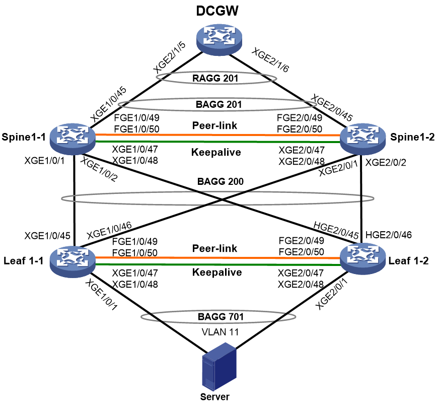
Table 3 Interface and IP address assignment and topology information for devices
|
Device |
Interface |
IP address |
Remarks |
|
Leaf1-1 |
XGE1/0/1 |
N/A |
Connected to the server. |
|
XGE1/0/45 |
N/A |
Connected to XGE1/0/1 on Spine1-1. |
|
|
XGE1/0/46 |
N/A |
Connected to XGE2/0/1 on Spine1-2. |
|
|
XGE1/0/47 |
N/A |
Physical interface attached to the keepalive link. |
|
|
XGE1/0/48 |
N/A |
Physical interface attached to the keepalive link. |
|
|
FGE1/0/49 |
N/A |
Physical interface attached to the peer link. |
|
|
FGE1/0/50 |
N/A |
Physical interface attached to the peer link. |
|
|
BAGG1 |
N/A |
Layer 2 aggregate interface attached to the peer link. |
|
|
RAGG1 |
1.1.1.1/30 |
Layer 3 aggregate interface attached to the keepalive link. |
|
|
BAGG200 |
N/A |
Connected to BAGG200 on the spine M-LAG system. |
|
|
BAGG701 |
N/A |
Connected to the server. |
|
|
Leaf1-2 |
XGE2/0/1 |
N/A |
Connected to the server. |
|
XGE2/0/45 |
N/A |
Connected to XGE1/0/2 on Spine1-1. |
|
|
XGE2/0/46 |
N/A |
Connected to XGE2/0/2 on Spine1-2. |
|
|
XGE2/0/47 |
N/A |
Physical interface attached to the keepalive link. |
|
|
XGE2/0/48 |
N/A |
Physical interface attached to the keepalive link. |
|
|
FGE2/0/49 |
N/A |
Physical interface attached to the peer link. |
|
|
FGE2/0/50 |
N/A |
Physical interface attached to the peer link. |
|
|
BAGG1 |
N/A |
Layer 2 aggregate interface attached to the peer link. |
|
|
RAGG1 |
1.1.1.2/30 |
Layer 3 aggregate interface attached to the keepalive link. |
|
|
BAGG200 |
N/A |
Connected to BAGG200 on the spine M-LAG system. |
|
|
BAGG701 |
N/A |
Connected to the server. |
|
|
Spine1-1 |
XGE1/0/1 |
N/A |
Connected to XGE1/0/45 on Leaf1-1. |
|
XGE1/0/2 |
N/A |
Connected to XGE2/0/45 on Leaf1-2. |
|
|
XGE1/0/45 |
N/A |
Connected to XGE2/1/5 on DCGW. |
|
|
XGE1/0/47 |
N/A |
Physical interface attached to the keepalive link. |
|
|
XGE1/0/48 |
N/A |
Physical interface attached to the keepalive link. |
|
|
FortyGigE1/0/49 |
N/A |
Physical interface attached to the peer link. |
|
|
FortyGigE1/0/50 |
N/A |
Physical interface attached to the peer link. |
|
|
BAGG1 |
N/A |
Layer 2 aggregate interface attached to the peer link. |
|
|
RAGG1 |
192.168.1.1/30 |
Layer 3 aggregate interface attached to the keepalive link. |
|
|
BAGG200 |
N/A |
Connected to BAGG200 on the leaf M-LAG system. |
|
|
BAGG201 |
N/A |
Connected to DCGW. |
|
|
VLAN-interface11 |
IP: 19.1.128.252/24 VRRP virtual IP: 19.1.128.254 |
Gateway for the server. |
|
|
VLAN-interface40 |
IP: 19.1.32.42/29 VRRP virtual IP: 19.1.32.44 |
Connected to DCGW (19.1.32.41/29) |
|
|
VLAN-interface4094 |
192.168.1.5/30 |
Before conversion: Used for IRF MAD. After conversion: Used for Layer 3 interconnection between M-LAG member devices if a dynamic routing protocol is configured for routing between the M-LAG system and upstream devices. |
|
|
Spine1-2 |
XGE2/0/1 |
N/A |
Connected to XGE1/0/46 on Leaf1-1. |
|
XGE2/0/2 |
N/A |
Connected to XGE2/0/46 on Leaf1-2. |
|
|
XGE2/0/45 |
N/A |
Connected to XGE2/1/6 on DCGW. |
|
|
XGE2/0/47 |
N/A |
Physical interface attached to the keepalive link. |
|
|
XGE2/0/48 |
N/A |
Physical interface attached to the keepalive link. |
|
|
FGE2/0/49 |
N/A |
Physical interface attached to the peer link. |
|
|
FGE2/0/50 |
N/A |
Physical interface attached to the peer link. |
|
|
BAGG1 |
N/A |
Layer 2 aggregate interface attached to the peer link. |
|
|
RAGG1 |
192.168.1.2/30 |
Layer 3 aggregate interface attached to the keepalive link. |
|
|
BAGG200 |
N/A |
Connected to BAGG200 on the leaf M-LAG system. |
|
|
BAGG201 |
N/A |
Connected to DCGW. |
|
|
VLAN-interface11 |
IP: 19.1.128.253/24 VRRP virtual IP: 19.1.128.254 |
Gateway for the server. |
|
|
VLAN-interface40 |
IP: 19.1.32.43/29 VRRP virtual IP: 19.1.32.44 |
Connected to DCGW (19.1.32.41/29). |
|
|
VLAN-interface4094 |
192.168.1.6/30 |
Before conversion: Used for IRF MAD. After conversion: Used for Layer 3 interconnection between M-LAG member devices if a dynamic routing protocol is configured for routing between the M-LAG system and upstream devices. |
Converting the leaf IRF fabric to an M-LAG system
In this example, the IRF master device is Leaf1-1 and the IRF subordinate device is Leaf1-2.
Configuration summary
2. Configuring M-LAG settings on the IRF subordinate device
4. Configuring M-LAG settings on the IRF master device
|
|
NOTE: As a best practice, prepare the settings in advance and quickly deploy the settings to reduce convergence time. |
Shutting down all service physical interfaces on the IRF subordinate device to switch over service traffic to the IRF master device
|
|
CAUTION: Strictly follow the steps in this section to avoid the IRF subordinate device being placed in Recovery state by MAD. Packet loss might occur when you bring up and shut down interfaces. Make sure you are fully aware of the operation on the network. |
# Shut down all service physical interfaces and BFD MAD physical interfaces (all physical interfaces except IRF physical interfaces) on the IRF subordinate device to switch over service traffic to the IRF master device.
[IRF] interface range ten-gigabitethernet 2/0/1 ten-gigabitethernet 2/0/45 to ten-gigabitethernet 2/0/48
[IRF-if-range] shutdown
[IRF-if-range] quit
# Shut down IRF physical interfaces on the IRF master device to lead in IRF split.
[IRF] interface range fortygige 1/0/49 fortygige 1/0/50
[IRF-if-range] shutdown
[IRF-if-range] quit
Configuring M-LAG settings on the IRF subordinate device
|
|
CAUTION: For a modular device, you must first convert the device operating mode from IRF to standalone and reboot the device for the mode conversion to take effect. Then, configure M-LAG settings in standalone mode. |
1. The member devices might use the same MAC address after the IRF fabric splits, which causes MAC address conflict. To avoid network issues caused by MAC address conflict, configure the IRF fabric to remove the specified IRF bridge MAC address (if any) and not retain its bridge MAC address after it splits:
# Configure the IRF fabric to change its bridge MAC address as soon as the address owner leaves.
[Leaf1-2] undo irf mac-address persistent
# Restore the default IRF bridge MAC address.
[Leaf1-2] undo irf mac-address
2. Configure M-LAG system settings:
# Set the data restoration interval to 300 seconds.
[Leaf1-2] m-lag restore-delay 300
# Set the M-LAG role priority of the device to 100. The device will become the primary device of the M-LAG system.
|
|
IMPORTANT: As a best practice, configure the IRF master device as the M-LAG secondary device and the IRF subordinate device as the M-LAG primary device. If you do not do so, the effective roles of the member devices might be inconsistent with those configured for the member devices after the M-LAG system is set up. In this case, role switchover might occur. Packets will be lost for about 50 seconds during the role switchover. |
[Leaf1-2] m-lag role priority 100
# Configure the M-LAG system MAC address. For the M-LAG member devices to be identified as one M-LAG system, you must configure the same M-LAG system MAC address on them.
[Leaf1-2] m-lag system-mac 0002-0002-0002
# Set the M-LAG system number. You must assign different M-LAG system numbers to the M-LAG member devices in an M-LAG system.
[Leaf1-2] m-lag system-number 2
# Set the M-LAG system priority. You must configure the same M-LAG system priority for the M-LAG member devices in an M-LAG system.
[Leaf1-2] m-lag system-priority 123
# Specify the destination and source IPv4 addresses of keepalive packets as 1.1.1.1 and 1.1.1.2, respectively.
[Leaf1-2] m-lag keepalive ip destination 1.1.1.1 source 1.1.1.2
# Enable M-LAG system auto-recovery and set the reload delay timer. By default, if only one M-LAG member device starts up in an M-LAG system, that M-LAG member device will be stuck in the None role with all its M-LAG interfaces being M-LAG DOWN after it starts up. The M-LAG interfaces cannot forward service traffic. To resolve this issue, perform this task.
[Leaf1-2] m-lag auto-recovery reload-delay 240
3. Configure M-LAG interfaces:
# Assign Layer 2 aggregate interface 200 (the interface connected to the spine devices) and Layer 2 aggregate interface 701 (the interface connected to the server) to M-LAG groups. Disable spanning tree on the M-LAG interfaces.
[Leaf1-2] interface bridge-aggregation 200
[Leaf1-2-Bridge-Aggregation200] port m-lag group 200
[Leaf1-2-Bridge-Aggregation200] undo stp enable
[Leaf1-2-Bridge-Aggregation200] quit
[Leaf1-2] interface bridge-aggregation 701
[Leaf1-2-Bridge-Aggregation701] port m-lag group 701
[Leaf1-2-Bridge-Aggregation701] undo stp enable
[Leaf1-2-Bridge-Aggregation701] quit
4. Configure the peer link:
# Remove Layer 2 aggregate interfaces 1 and 2 used for IRF MAD and re-create Layer 2 aggregate interface 1. The aggregate interface will be used as the peer-link interface.
[Leaf1-2] undo interface bridge-aggregation 1
[Leaf1-2] undo interface bridge-aggregation 2
[Leaf1-2] interface bridge-aggregation 1
# Remove IRF physical interfaces FortyGigE 2/0/49 and FortyGigE 2/0/50 from IRF-port 2/2 and assign the interfaces to aggregation group 1. The physical interfaces will be attached to the peer link.
[Leaf1-2] interface range fortygige 2/0/49 fortygige 2/0/50
[Leaf1-2-if-range] shutdown
[Leaf1-2-if-range] quit
[Leaf1-2] irf-port 2/2
[Leaf1-2-irf-port2/2] undo port group interface fortygige 2/0/49
[Leaf1-2-irf-port2/2] undo port group interface fortygige 2/0/50
[Leaf1-2-irf-port2/2] quit
[Leaf1-2] interface range fortygige 2/0/49 fortygige 2/0/50
[Leaf1-2-if-range] port link-aggregation group 1
[Leaf1-2-if-range] quit
# Configure Layer 2 aggregate interface 1 as the peer-link interface.
[Leaf1-2] interface Bridge-Aggregation 1
[Leaf1-2-Bridge-Aggregation1] port link-type trunk
[Leaf1-2-Bridge-Aggregation1] port trunk permit vlan all
[Leaf1-2-Bridge-Aggregation1] link-aggregation mode dynamic
[Leaf1-2-Bridge-Aggregation1] port m-lag peer-link 1
[Leaf1-2-Bridge-Aggregation1] quit
5. Configure the keepalive link:
# Remove VLAN-interface 4094 used for IRF MAD and create Layer 3 aggregate interface 1. The aggregate interface will be attached to the keepalive link.
[Leaf1-2] undo interface vlan-interface 4094
[Leaf1-2] interface route-aggregation 1
[Leaf1-2-Route-Aggregation1] quit
# Assign interfaces Ten-GigabitEthernet 2/0/47 and Ten-GigabitEthernet 2/0/48 to Layer 3 aggregation group 1. The physical interfaces will be attached to the keepalive link.
[Leaf1-2] interface range ten-gigabitethernet 2/0/47 ten-gigabitethernet 2/0/48
[Leaf1-2-if-range] port link-mode route
[Leaf1-2-if-range] port link-aggregation group 1
[Leaf1-2-if-range] quit
# Configure Layer 3 aggregation group 1 to operate in dynamic aggregation mode and assign an IP address to the aggregate interface.
[Leaf1-2] interface route-aggregation 1
[Leaf1-2-Route-Aggregation1] link-aggregation mode dynamic
[Leaf1-2-Route-Aggregation1] ip address 1.1.1.2 255.255.255.0
[Leaf1-2-Route-Aggregation1] quit
6. Add the interfaces attached to the keepalive link to the user-configured list of excluded ports, which will not be shut down by M-LAG MAD when the M-LAG system splits.
[Leaf1-2] m-lag mad exclude interface route-aggregation 1
[Leaf1-2] m-lag mad exclude interface ten-gigabitethernet 2/0/47
[Leaf1-2] m-lag mad exclude interface ten-gigabitethernet 2/0/48
Bringing up interfaces on the IRF subordinate device and shutting down interfaces on the IRF master device to switch over traffic to the IRF subordinate device
|
|
CAUTION: To reduce traffic interruption time, shut down service interfaces on the IRF master device immediately after the service interfaces on the IRF subordinate device are brought up. |
# On Leaf1-2, bring up all service physical and logical interfaces, including the physical and logical interfaces attached to the peer link, physical and logical interfaces attached to the keepalive link, and M-LAG interfaces and their member ports.
[Leaf1-2] interface range ten-gigabitethernet 2/0/1 ten-gigabitethernet 2/0/45 to ten-gigabitethernet 2/0/48 fortygige 2/0/49 fortygige 2/0/50 bridge-aggregation 200 bridge-aggregation 701 bridge-aggregation 1 route-aggregation 1
[Leaf1-2-if-range] undo shutdown
[Leaf1-2-if-range] quit
# On Leaf1-1, shut down all service physical interfaces and the physical interfaces used for IRF MAD.
[Leaf1-1] interface range ten-gigabitethernet 1/0/1 ten-gigabitethernet 1/0/45 to ten-gigabitethernet 1/0/48
[Leaf1-1-if-range] shutdown
[Leaf1-1-if-range] quit
Configuring M-LAG settings on the IRF master device
|
|
CAUTION: For a modular device, you must first convert the device operating mode from IRF to standalone and reboot the device for the mode conversion to take effect. Then, configure M-LAG settings in standalone mode. |
1. The member devices might use the same MAC address after the IRF fabric splits, which causes MAC address conflict. To avoid network issues caused by MAC address conflict, configure the IRF fabric to remove the specified IRF bridge MAC address (if any) and not retain its bridge MAC address after it splits:
# Configure the IRF fabric to change its bridge MAC address as soon as the address owner leaves.
[Leaf1-1] undo irf mac-address persistent
# Restore the default IRF bridge MAC address.
[Leaf1-1] undo irf mac-address
2. Configure M-LAG system settings:
# Set the data restoration interval to 300 seconds.
[Leaf1-1] m-lag restore-delay 300
# Configure the M-LAG system MAC address. For the M-LAG member devices to be identified as one M-LAG system, you must configure the same M-LAG system MAC address on them.
[Leaf1-1] m-lag system-mac 0002-0002-0002
# Set the M-LAG system number. You must assign different M-LAG system numbers to the M-LAG member devices in an M-LAG system.
[Leaf1-1] m-lag system-number 1
# Set the M-LAG system priority. You must configure the same M-LAG system priority for the M-LAG member devices in an M-LAG system.
[Leaf1-1] m-lag system-priority 123
# Specify the destination and source IPv4 addresses of keepalive packets as 1.1.1.2 and 1.1.1.1, respectively.
[Leaf1-1] m-lag keepalive ip destination 1.1.1.2 source 1.1.1.1
3. Configure M-LAG interfaces:
# Assign Layer 2 aggregate interface 200 (the interface connected to the spine devices) and Layer 2 aggregate interface 701 (the interface connected to the server) to M-LAG groups. Disable spanning tree on the M-LAG interfaces.
[Leaf1-1] interface bridge-aggregation 200
[Leaf1-1-Bridge-Aggregation200] port m-lag group 200
[Leaf1-1-Bridge-Aggregation200] undo stp enable
[Leaf1-1-Bridge-Aggregation200] quit
[Leaf1-1] interface bridge-aggregation 701
[Leaf1-1-Bridge-Aggregation701] port m-lag group 701
[Leaf1-1-Bridge-Aggregation701] undo stp enable
[Leaf1-1-Bridge-Aggregation701] quit
4. Configure the peer-link interface:
# Remove Layer 2 aggregate interfaces 1 and 2 used for IRF MAD and re-create Layer 2 aggregate interface 1. The aggregate interface will be used as the peer-link interface.
[Leaf1-1] undo interface bridge-aggregation 1
[Leaf1-1] undo interface bridge-aggregation 2
[Leaf1-1] interface bridge-aggregation 1
# Remove IRF physical interfaces FortyGigE 1/0/49 and FortyGigE 1/0/50 from IRF-port 1/1 and assign the interfaces to aggregation group 1. The physical interfaces will be attached to the peer link.
[Leaf1-1] irf-port 1/1
[Leaf1-1-irf-port1/1] undo port group interface fortygige 1/0/49
[Leaf1-1-irf-port1/1] undo port group interface fortygige 1/0/50
[Leaf1-1-irf-port1/1] quit
[Leaf1-1] interface range fortygige 1/0/49 fortygige 1/0/50
[Leaf1-1-if-range] port link-aggregation group 1
[Leaf1-1-if-range] quit
# Configure Layer 2 aggregate interface 1 as the peer-link interface.
[Leaf1-1] interface bridge-aggregation 1
[Leaf1-1-Bridge-Aggregation1] port link-type trunk
[Leaf1-1-Bridge-Aggregation1] port trunk permit vlan all
[Leaf1-1-Bridge-Aggregation1] link-aggregation mode dynamic
[Leaf1-1-Bridge-Aggregation1] port m-lag peer-link 1
[Leaf1-1-Bridge-Aggregation1] quit
5. Configure the interfaces attached to the keepalive link:
# Remove VLAN-interface 4094 used for IRF MAD and create Layer 3 aggregate interface 1. The aggregate interface will be attached to the keepalive link.
[Leaf1-1] undo interface Vlan-interface4094
[Leaf1-1] interface route-aggregation 1
# Assign interfaces Ten-GigabitEthernet 1/0/47 and Ten-GigabitEthernet 1/0/48 to Layer 3 aggregation group 1. The physical interfaces will be attached to the keepalive link.
[Leaf1-1] interface range ten-gigabitethernet 1/0/47 ten-gigabitethernet 1/0/48
[Leaf1-1-if-range] port link-mode route
[Leaf1-1-if-range] port link-aggregation group 1
[Leaf1-1-if-range] quit
# Configure Layer 3 aggregation group 1 to operate in dynamic aggregation mode and assign an IP address to the aggregate interface.
[Leaf1-1] interface route-aggregation 1
[Leaf1-1-Route-Aggregation1] link-aggregation mode dynamic
[Leaf1-1-Route-Aggregation1] ip address 1.1.1.1 255.255.255.0
[Leaf1-1-Route-Aggregation1] quit
6. Add the interfaces attached to the keepalive link to the user-configured list of excluded ports, which will not be shut down by M-LAG MAD when the M-LAG system splits.
[Leaf1-1] m-lag mad exclude interface route-aggregation 1
[Leaf1-1] m-lag mad exclude interface ten-gigabitethernet 1/0/47
[Leaf1-1] m-lag mad exclude interface ten-gigabitethernet 1/0/48
Bringing up interfaces on the IRF master device to complete M-LAG system setup and distribute traffic to both the member devices
|
|
IMPORTANT: To bring up interfaces on the primary device by using the undo shutdown command, use the following procedure: 1. Bring up interfaces used to set up the peer link. 2. Bring up the interfaces used to set up the keepalive link. 3. Wait for a period of time, and execute the display m-lag summary command to verify that the M-LAG member devices are operating correctly. 4. Bring up all service physical and logical interfaces. |
# On Leaf1-1, bring up the interfaces attached to the peer link.
[Leaf1-1] interface range fortygige 1/0/49 fortygige 1/0/50 bridge-aggregation 1
[Leaf1-1-if-range] undo shutdown
[Leaf1-1-if-range] quit
# On Leaf1-1, bring up the interfaces attached to the keepalive link.
[Leaf1-1] interface range ten-gigabitethernet 1/0/47 to ten-gigabitethernet 1/0/48 route-aggregation 1
[Leaf1-1-if-range] undo shutdown
[Leaf1-1-if-range] quit
# On Leaf1-1, bring up all service physical and logical interfaces, including uplink interfaces, downlink interfaces, and M-LAG interfaces and their member ports.
[Leaf1-1] interface range ten-gigabitethernet 1/0/1 ten-gigabitethernet 1/0/45 ten-gigabitethernet 1/0/46 bridge-aggregation 200 bridge-aggregation 701
[Leaf1-1-if-range] undo shutdown
[Leaf1-1-if-range] quit
# Save the settings on both the member devices.
[Leaf1-1] save
[Leaf1-2] save
Converting the spine IRF fabric to an M-LAG system
In this example, the IRF master device is Spine1-1 and the IRF subordinate device is Spine1-2.
Configuration summary
2. Configuring M-LAG settings on the IRF subordinate device
4. Configuring M-LAG settings on the IRF master device
|
|
NOTE: · As a best practice, prepare the settings in advance and quickly deploy the settings to reduce convergence time. · After conversion, specify the original IP addresses of Layer 3 interfaces created before conversion as the virtual IP addresses of VRRP groups, and reconfigure other IP addresses for the Layer 3 interfaces. |
Shutting down all service physical interfaces on the IRF subordinate device to switch over service traffic to the IRF master device
|
|
CAUTION: Strictly follow the steps in this section to avoid the IRF subordinate device being placed in Recovery state by MAD. Packet loss might occur when you bring up and shut down interfaces. Make sure you are fully aware of the operation on the network. |
# Shut down all service physical interfaces and BFD MAD physical interfaces (all physical interfaces except IRF physical interfaces) on the IRF subordinate device to switch over service traffic to the IRF master device.
[IRF] interface range ten-gigabitethernet 2/0/1 ten-gigabitethernet 2/0/2 ten-gigabitethernet 2/0/45 ten-gigabitethernet 2/0/47 ten-gigabitethernet 2/0/48
[IRF-if-range] shutdown
[IRF-if-range] quit
# Shut down IRF physical interfaces on the IRF master device to lead in IRF split.
[IRF] interface range fortygige 1/0/49 fortygige 1/0/50
[IRF-if-range] shutdown
[IRF-if-range] quit
Configuring M-LAG settings on the IRF subordinate device
|
|
CAUTION: For a modular device, you must first convert the device operating mode from IRF to standalone and reboot the device for the mode conversion to take effect. Then, configure M-LAG settings in standalone mode. |
1. The member devices might use the same MAC address after the IRF fabric splits, which causes MAC address conflict. To avoid network issues caused by MAC address conflict, configure the IRF fabric to remove the specified IRF bridge MAC address (if any) and not retain its bridge MAC address after it splits:
# Configure the IRF fabric to change its bridge MAC address as soon as the address owner leaves.
[Spine1-2] undo irf mac-address persistent
# Restore the default IRF bridge MAC address.
[Spine1-2] undo irf mac-address
2. Configure M-LAG system settings:
# Set the data restoration interval to 300 seconds.
[Spine1-2] m-lag restore-delay 300
# Set the M-LAG role priority of the device to 100. The device will become the primary device of the M-LAG system.
|
|
IMPORTANT: As a best practice, configure the IRF master device as the M-LAG secondary device and the IRF subordinate device as the M-LAG primary device. If you do not do so, the effective roles of the member devices might be inconsistent with those configured for the member devices after the M-LAG system is set up. In this case, role switchover might occur. Packets will be lost for about 50 seconds during the role switchover. |
[Spine1-2] m-lag role priority 100
# Configure the M-LAG system MAC address. For the M-LAG member devices to be identified as one M-LAG system, you must configure the same M-LAG system MAC address on them.
[Spine1-2] m-lag system-mac 0001-0001-0001
# Set the M-LAG system number. You must assign different M-LAG system numbers to the M-LAG member devices in an M-LAG system.
[Spine1-2] m-lag system-number 2
# Set the M-LAG system priority. You must configure the same M-LAG system priority for the M-LAG member devices in an M-LAG system.
[Spine1-2] m-lag system-priority 123
# Specify the destination and source IPv4 addresses of keepalive packets as 192.168.1.1 and 192.168.1.2, respectively.
[Spine1-2] m-lag keepalive ip destination 192.168.1.1 source 192.168.1.2
# Enable M-LAG system auto-recovery and set the reload delay timer. By default, if only one M-LAG member device starts up in an M-LAG system, that M-LAG member device will be stuck in the None role with all its M-LAG interfaces being M-LAG DOWN after it starts up. The M-LAG interfaces cannot forward service traffic. To resolve this issue, perform this task.
[Spine1-2] m-lag auto-recovery reload-delay 240
3. Configure M-LAG interfaces:
# Assign Layer 2 aggregate interface 200 (the interface connected to the leaf M-LAG system) and Layer 2 aggregate interface 201 (the interface connected to DCGW) to M-LAG groups. Disable spanning tree on the M-LAG interfaces.
[Spine1-2] interface bridge-aggregation 200
[Spine1-2-Bridge-Aggregation200] port m-lag group 200
[Spine1-2-Bridge-Aggregation200] undo stp enable
[Spine1-2-Bridge-Aggregation200] quit
[Spine1-2] interface bridge-aggregation 201
[Spine1-2-Bridge-Aggregation201] port m-lag group 201
[Spine1-2-Bridge-Aggregation201] undo stp enable
[Spine1-2-Bridge-Aggregation201] quit
4. Configure VRRP on the VLAN interfaces of the VLANs to which M-LAG interfaces belong:
# Specify the original IP addresses of the VLAN interfaces as the virtual IP addresses of VRRP groups and reconfigure another IP address in the same subnet as the original IP address for each of the VLAN interfaces. Disable the preemptive mode for the device in the VRRP groups. Because Spine1-2 starts up before Spine1-1, it will become the VRRP master router.
[Spine1-2] interface vlan-interface 11
[Spine1-2-Vlan-interface11] ip address 19.1.128.253 255.255.255.0
[Spine1-2-Vlan-interface11] vrrp vrid 11 virtual-ip 19.1.128.254
[Spine1-2-Vlan-interface11] undo vrrp vrid 11 preempt-mode
[Spine1-2-Vlan-interface11] quit
[Spine1-2] interface vlan-interface 40
[Spine1-2-Vlan-interface40] ip address 19.1.32.43 255.255.255.248
[Spine1-2-Vlan-interface40] vrrp vrid 40 virtual-ip 19.1.32.44
[Spine1-2-Vlan-interface40] undo vrrp vrid 40 preempt-mode
[Spine1-2-Vlan-interface40] quit
5. Configure the peer link:
# Remove Layer 2 aggregate interfaces 1 and 2 used for IRF MAD and re-create Layer 2 aggregate interface 1. The aggregate interface will be used as the peer-link interface.
[Spine1-2] undo interface bridge-aggregation 1
[Spine1-2] undo interface bridge-aggregation 2
[Spine1-2] interface bridge-aggregation 1
[Spine1-2-Bridge-Aggregation1] quit
# Remove IRF physical interfaces FortyGigE 2/0/49 and FortyGigE 2/0/50 from IRF-port 2/2 and assign the interfaces to aggregation group 1. The physical interfaces will be attached to the peer link.
[Spine1-2] irf-port 2/2
[Spine1-2-irf-port2/2] undo port group interface fortygige 2/0/49
[Spine1-2-irf-port2/2] undo port group interface fortygige 2/0/50
[Spine1-2-irf-port2/2] quit
[Spine1-2] interface range fortygige 2/0/49 fortygige 2/0/50
[Spine1-2-if-range] port link-aggregation group 1
[Spine1-2-if-range] quit
# Configure Layer 2 aggregate interface 1 as the peer-link interface.
[Spine1-2] interface bridge-aggregation 1
[Spine1-2-Bridge-Aggregation1] port link-type trunk
[Spine1-2-Bridge-Aggregation1] port trunk permit vlan all
[Spine1-2-Bridge-Aggregation1] link-aggregation mode dynamic
[Spine1-2-Bridge-Aggregation1] port m-lag peer-link 1
[Spine1-2-Bridge-Aggregation1] quit
6. Configure the interfaces attached to the keepalive link:
# Create Layer 3 aggregate interface 1.
[Spine1-2] undo interface vlan-interface 4094
[Spine1-2] interface route-aggregation 1
# Assign interfaces Ten-GigabitEthernet 2/0/47 and Ten-GigabitEthernet 2/0/48 to Layer 3 aggregation group 1. The physical interfaces will be attached to the keepalive link.
[Spine1-2] interface range ten-gigabitethernet 2/0/47 ten-gigabitethernet 2/0/48
[Spine1-2-if-range] port link-mode route
[Spine1-2-if-range] port link-aggregation group 1
[Spine1-2-if-range] quit
# Configure Layer 3 aggregation group 1 to operate in dynamic aggregation mode and assign an IP address to the aggregate interface.
[Spine1-2] interface route-aggregation1
[Spine1-2-Route-Aggregation1] link-aggregation mode dynamic
[Spine1-2-Route-Aggregation1] ip address 1.1.1.2 255.255.255.0
[Spine1-2-Route-Aggregation1] quit
7. Add interfaces to the user-configured list of excluded ports, which will not be shut down by M-LAG MAD when the M-LAG system splits.
[Spine1-2] m-lag mad exclude interface route-aggregation 1
[Spine1-2] m-lag mad exclude interface ten-gigabitethernet 2/0/47
[Spine1-2] m-lag mad exclude interface ten-gigabitethernet 2/0/48
[Spine1-2] m-lag mad exclude interface vlan-interface 11
[Spine1-2] m-lag mad exclude interface vlan-interface 40
Bringing up interfaces on the IRF subordinate device and shutting down interfaces on the IRF master device to switch over traffic to the IRF subordinate device
|
|
CAUTION: To reduce traffic interruption time, shut down service interfaces on the IRF master device immediately after the service interfaces on the IRF subordinate device are brought up. |
# On Spine1-2, bring up all service physical and logical interfaces, including the physical and logical interfaces attached to the peer link, the physical and logical interfaces attached to the keepalive link, M-LAG interfaces and member ports, VLAN-interface 11 (server gateway), and VLAN-interface 40 (the Layer 3 interface connected to DCGW).
[Spine1-2] interface range ten-gigabitethernet 2/0/1 ten-gigabitethernet 2/0/2 ten-gigabitethernet 2/0/45 ten-gigabitethernet 2/0/47 ten-gigabitethernet 2/0/48 fortygige 2/0/49 fortygige 2/0/50 bridge-aggregation 1 bridge-aggregation 200 bridge-aggregation 201 route-aggregation 1 vlan-interface 11 vlan-interface 40
[Spine1-2-if-range] undo shutdown
[Spine1-2-if-range] quit
# On Spine1-1, shut down all service physical interfaces and BFD MAD physical interfaces.
[Spine1-1] interface range ten-gigabitethernet 1/0/1 ten-gigabitethernet 1/0/2 ten-gigabitethernet 1/0/45 ten-gigabitethernet 1/0/47 ten-gigabitethernet 1/0/48
[Spine1-1-if-range] shutdown
[Spine1-1-if-range] quit
Configuring M-LAG settings on the IRF master device
|
|
CAUTION: For a modular device, you must first convert the device operating mode from IRF to standalone and reboot the device for the mode conversion to take effect. Then, configure M-LAG settings in standalone mode. |
1. The member devices might use the same MAC address after the IRF fabric splits, which causes MAC address conflict. To avoid network issues caused by MAC address conflict, configure the IRF fabric to remove the specified IRF bridge MAC address (if any) and not retain its bridge MAC address after it splits:
# Configure the IRF fabric to change its bridge MAC address as soon as the address owner leaves.
[Spine1-1] undo irf mac-address persistent
# Restore the default IRF bridge MAC address.
[Spine1-1] undo irf mac-address
2. Configure M-LAG system settings:
# Set the data restoration interval to 300 seconds.
[Spine1-1] m-lag restore-delay 300
# Configure the M-LAG system MAC address. For the M-LAG member devices to be identified as one M-LAG system, you must configure the same M-LAG system MAC address on them.
[Spine1-1] m-lag system-mac 0001-0001-0001
# Set the M-LAG system number. You must assign different M-LAG system numbers to the M-LAG member devices in an M-LAG system.
[Spine1-1] m-lag system-number 1
# Set the M-LAG system priority. You must configure the same M-LAG system priority for the M-LAG member devices in an M-LAG system.
[Spine1-1] m-lag system-priority 123
# Specify the destination and source IPv4 addresses of keepalive packets as 192.168.1.2 and 192.168.1.1, respectively.
[Spine1-1] m-lag keepalive ip destination 192.168.1.2 source 192.168.1.1
3. Configure M-LAG interfaces:
# Assign Layer 2 aggregate interface 200 (the interface connected to the leaf M-LAG system) and Layer 2 aggregate interface 201 (the interface connected to DCGW) to M-LAG groups. Disable spanning tree on the M-LAG interfaces.
[Spine1-1] interface bridge-aggregation 200
[Spine1-1-Bridge-Aggregation200] port m-lag group 200
[Spine1-1-Bridge-Aggregation200] undo stp enable
[Spine1-1-Bridge-Aggregation200] quit
[Spine1-1] interface bridge-aggregation 201
[Spine1-1-Bridge-Aggregation201] port m-lag group 201
[Spine1-1-Bridge-Aggregation201] undo stp enable
[Spine1-1-Bridge-Aggregation201] quit
4. Configure VRRP on the VLAN interfaces of the VLANs to which M-LAG interfaces belong:
# Specify the original IP addresses of the VLAN interfaces as the virtual IP addresses of VRRP groups and reconfigure another IP address in the same subnet as the original IP address for each of the VLAN interfaces. Disable the preemptive mode for the device in the VRRP groups.
[Spine1-1] interface vlan-interface 11
[Spine1-1-Vlan-interface11] ip address 19.1.128.252 255.255.255.0
[Spine1-1-Vlan-interface11] vrrp vrid 11 virtual-ip 19.1.128.254
[Spine1-1-Vlan-interface11] undo vrrp vrid 11 preempt-mode
[Spine1-1-Vlan-interface11] quit
[Spine1-1] interface vlan-interface 40
[Spine1-1-Vlan-interface40] ip address 19.1.32.42 255.255.255.248
[Spine1-1-Vlan-interface40] vrrp vrid 40 virtual-ip 19.1.32.44
[Spine1-1-Vlan-interface40] undo vrrp vrid 40 preempt-mode
[Spine1-1-Vlan-interface40] quit
5. Configure the peer-link interface:
# Remove Layer 2 aggregate interfaces 1 and 2 used for IRF MAD and re-create Layer 2 aggregate interface 1. The aggregate interface will be used as the peer-link interface.
[Spine1-1] undo interface bridge-aggregation 1
[Spine1-1] undo interface bridge-aggregation 2
[Spine1-1] interface bridge-aggregation 1
# Remove IRF physical interfaces FortyGigE 1/0/49 and FortyGigE 1/0/50 from IRF-port 1/1 and assign the interfaces to aggregation group 1. The physical interfaces will be attached to the peer link.
[Spine1-1] irf-port 1/1
[Spine1-1-irf-port1/1] undo port group interface fortygige 1/0/49
[Spine1-1-irf-port1/1] undo port group interface fortygige 1/0/50
[Spine1-1-irf-port1/1] quit
[Spine1-1] interface range fortygige 1/0/49 fortygige 1/0/50
[Spine1-1-if-range] port link-aggregation group 1
[Spine1-1-if-range] quit
# Configure Layer 2 aggregate interface 1 as the peer-link interface.
[Spine1-1] interface Bridge-Aggregation 1
[Spine1-1-Bridge-Aggregation1] port link-type trunk
[Spine1-1-Bridge-Aggregation1] port trunk permit vlan all
[Spine1-1-Bridge-Aggregation1] link-aggregation mode dynamic
[Spine1-1-Bridge-Aggregation1] port m-lag peer-link 1
[Spine1-1-Bridge-Aggregation1] quit
# Remove VLAN-interface 4094 used for IRF MAD and create Layer 3 aggregate interface 1. The aggregate interface will be attached to the keepalive link.
[Spine1-1] undo interface vlan-interface 4094
[Spine1-1] interface route-aggregation 1
[Spine1-1-Route-Aggregation1] quit
# Assign interfaces Ten-GigabitEthernet 1/0/47 and Ten-GigabitEthernet 1/0/48 to Layer 3 aggregation group 1. The physical interfaces will be attached to the keepalive link.
[Spine1-1] interface range ten-gigabitethernet 1/0/47 ten-gigabitethernet 1/0/48
[Spine1-1-if-range] port link-mode route
[Spine1-1-if-range] port link-aggregation group 1
[Spine1-1-if-range] quit
# Configure Layer 3 aggregation group 1 to operate in dynamic aggregation mode and assign an IP address to the aggregate interface.
[Spine1-1] interface route-aggregation1
[Spine1-1-Route-Aggregation1] link-aggregation mode dynamic
[Spine1-1-Route-Aggregation1] ip address 1.1.1.1 255.255.255.0
[Spine1-1-Route-Aggregation1] quit
6. Add interfaces to the user-configured list of excluded ports, which will not be shut down by M-LAG MAD when the M-LAG system splits.
[Spine1-1] m-lag mad exclude interface route-aggregation 1
[Spine1-1] m-lag mad exclude interface ten-gigabitethernet 1/0/47
[Spine1-1] m-lag mad exclude interface ten-gigabitethernet 1/0/48
[Spine1-1] m-lag mad exclude interface vlan-interface 11
[Spine1-1] m-lag mad exclude interface vlan-interface 40
Bringing up interfaces on the IRF master device to complete M-LAG system setup and distribute traffic to both the member devices
|
|
IMPORTANT: To bring up interfaces on the primary device by using the undo shutdown command, use the following procedure: 1. Bring up interfaces used to set up the peer link. 2. Bring up the interfaces used to set up the keepalive link. 3. Wait for a period of time, and execute the display m-lag summary command to verify that the M-LAG member devices are operating correctly. 4. Bring up all service physical and logical interfaces. |
# On Spine1-1, bring up the interfaces attached to the peer link.
[Spine1-1] interface range fortygige 1/0/49 fortygige 1/0/50 bridge-aggregation 1
[Spine1-1-if-range] undo shutdown
[Spine1-1-if-range] quit
# On Spine1-1, bring up the interfaces attached to the keepalive link.
[Spine1-1] interface range ten-gigabitethernet 1/0/47 ten-gigabitethernet 1/0/48 route-aggregation 1
[Spine1-1-if-range] undo shutdown
[Spine1-1-if-range] quit
# On Spine1-1, bring up all service physical and logical interfaces, including the M-LAG interfaces and their member ports, VLAN-interface 11 (gateway interface for the server), and VLAN-interface 40 (the Layer 3 interface connected to DCGW).
[Spine1-1] interface range ten-gigabitethernet 1/0/1 ten-gigabitethernet 1/0/2 ten-gigabitethernet 1/0/45 bridge-aggregation 200 bridge-aggregation 201 vlan-interface 11 vlan-interface 40
[Spine1-1-if-range] undo shutdown
[Spine1-1-if-range] quit
# Save the settings on both the member devices.
[Spine1-1] save
[Spine1-2] save
Network 2 after conversion: The spine devices are connected to DCGW through directly connected Layer 3 interfaces and use dynamic routing to reach the external network attached to DCGW
Conversion key points and network diagram
The conversion key points for the leaf IRF fabric are as follows:
1. Change the network scheme from IRF fabric to M-LAG system.
2. Convert the IRF physical interfaces to physical interfaces attached to the peer link.
3. Convert the physical interfaces used for IRF MAD to physical interfaces attached to the keepalive link.
4. Change the multichassis aggregate interfaces that are connected to the server and upstream devices to M-LAG interfaces.
The conversion key points for the spine IRF fabric are as follows:
1. Change the network scheme from IRF fabric to M-LAG system.
2. Convert the IRF physical interfaces to physical interfaces attached to the peer link.
3. Convert the physical interfaces used for IRF MAD to physical interfaces attached to the keepalive link.
4. Convert the multichassis aggregate interfaces that are connected to downstream devices to M-LAG interfaces.
5. Change the interfaces connected to DCGW to Layer 3 Ethernet interfaces, enable OSPF on the interfaces, and redistribute direct routes to OSPF.
6. Configure VRRP on all Layer 3 interfaces for M-LAG interfaces and disable the preemptive mode for each device in VRRP groups.
7. Set up routes between the M-LAG primary and secondary devices to ensure that the M-LAG member devices have Layer 3 connectivity. This configuration is used to protect services in case of uplink failure or M-LAG system failure.
8. After the IRF fabric is converted to an M-LAG system, the two member devices run independently. They use the same IP addresses for Layer 3 interfaces. To remove IP address conflicts, configure new IP addresses for the Layer 3 interfaces.
The conversion key points for DCGW are reconfiguring IP addresses for interfaces, enabling OSPF, and redistributing direct routes to OSPF.
Figure 4 Network diagram (after conversion)
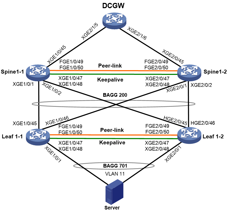
Table 4 Interface and IP address assignment and topology information for devices
|
Device |
Interface |
IP address |
Remarks |
|
Leaf1-1 |
XGE1/0/1 |
N/A |
Connected to the server |
|
XGE1/0/45 |
N/A |
Connected to XGE1/0/1 on Spine1-1. |
|
|
XGE1/0/46 |
N/A |
Connected to XGE2/0/1 on Spine1-2. |
|
|
XGE1/0/47 |
N/A |
Physical interface attached to the keepalive link. |
|
|
XGE1/0/48 |
N/A |
Physical interface attached to the keepalive link. |
|
|
FGE1/0/49 |
N/A |
Physical interface attached to the peer link. |
|
|
FGE1/0/50 |
N/A |
Physical interface attached to the peer link. |
|
|
BAGG1 |
N/A |
Layer 2 aggregate interface attached to the peer ink. |
|
|
RAGG1 |
1.1.1.1/30 |
Layer 3 aggregate interface attached to the keepalive link. |
|
|
BAGG200 |
N/A |
Connected to BAGG200 on the spine M-LAG system. |
|
|
BAGG701 |
N/A |
Connected to the server. |
|
|
Leaf1-2 |
XGE2/0/1 |
N/A |
Connected to the server. |
|
XGE2/0/45 |
N/A |
Connected to XGE1/0/2 on Spine1-1. |
|
|
XGE2/0/46 |
N/A |
Connected to XGE2/0/2 on Spine1-2. |
|
|
XGE2/0/47 |
N/A |
Physical interface attached to the keepalive link. |
|
|
XGE2/0/48 |
N/A |
Physical interface attached to the keepalive link. |
|
|
FGE2/0/49 |
N/A |
Physical interface attached to the peer link. |
|
|
FGE2/0/50 |
N/A |
Physical interface attached to the peer link. |
|
|
BAGG1 |
N/A |
Layer 2 aggregate interface attached to the peer link. |
|
|
RAGG1 |
1.1.1.2/30 |
Layer 3 aggregate interface attached to the keepalive link. |
|
|
BAGG200 |
N/A |
Connected to BAGG200 on the spine M-LAG system. |
|
|
BAGG701 |
N/A |
Connected to the server. |
|
|
Spine1-1 |
XGE1/0/1 |
N/A |
Connected to XGE1/0/45 on Leaf1-1. |
|
XGE1/0/2 |
N/A |
Connected to XGE2/0/45 on Leaf1-2. |
|
|
XGE1/0/45 |
19.1.32.42/30 |
Connected to XGE2/1/5 (19.1.32.41/30) on DCGW. |
|
|
XGE1/0/47 |
N/A |
Physical interface attached to the keepalive link. |
|
|
XGE1/0/48 |
N/A |
Physical interface attached to the keepalive link. |
|
|
FortyGigE1/0/49 |
N/A |
Physical interface attached to the peer link. |
|
|
FortyGigE1/0/50 |
N/A |
Physical interface attached to the peer link. |
|
|
BAGG1 |
N/A |
Layer 2 aggregate interface attached to the peer link. |
|
|
RAGG1 |
192.168.1.1/30 |
Layer 3 aggregate interface attached to the keepalive link. |
|
|
BAGG200 |
N/A |
Connected to BAGG200 on the leaf M-LAG system. |
|
|
BAGG201 |
N/A |
Connected to DCGW. |
|
|
VLAN-interface11 |
IP: 19.1.128.252/24 VRRP virtual IP: 19.1.128.254 |
Gateway for the server. |
|
|
VLAN-interface4094 |
192.168.1.5/30 |
Before conversion: Used for IRF MAD. After conversion: Used for Layer 3 interconnection between M-LAG member devices when a dynamic routing protocol is configured for routing between the M-LAG system and upstream devices. |
|
|
Spine1-2 |
XGE2/0/1 |
N/A |
Connected to XGE1/0/46 on Leaf1-1. |
|
XGE2/0/2 |
N/A |
Connected to XGE2/0/46 on Leaf1-2. |
|
|
XGE2/0/45 |
19.1.32.46/30 |
Connected to XGE2/1/6 (19.1.32.45/30) on DCGW. |
|
|
XGE2/0/47 |
N/A |
Physical interface attached to the keepalive link. |
|
|
XGE2/0/48 |
N/A |
Physical interface attached to the keepalive link. |
|
|
FGE2/0/49 |
N/A |
Physical interface attached to the peer link. |
|
|
FGE2/0/50 |
N/A |
Physical interface attached to the peer link. |
|
|
BAGG1 |
N/A |
Layer 2 aggregate interface attached to the peer link. |
|
|
RAGG1 |
192.168.1.2/30 |
Layer 3 aggregate interface attached to the keepalive link. |
|
|
BAGG200 |
N/A |
Connected to BAGG200 on the leaf M-LAG system. |
|
|
BAGG201 |
N/A |
Connected to DCGW. |
|
|
VLAN-interface11 |
IP: 19.1.128.253/24 VRRP virtual IP: 19.1.128.254 |
Gateway for the server. |
|
|
VLAN-interface4094 |
192.168.1.6/30 |
Before conversion: Used for IRF MAD. After conversion: Used for Layer 3 interconnection between M-LAG member devices when a dynamic routing protocol is configured for routing between the M-LAG system and upstream devices. |
Converting the leaf IRF fabric to an M-LAG system
For more information about the procedure and restrictions, see "Converting the leaf IRF fabric to an M-LAG system."
Converting the spine IRF fabric to an M-LAG system
In this example, the IRF master device is Spine1-1 and the IRF subordinate device is Spine1-2.
Configuration summary
2. Configuring M-LAG settings on the IRF subordinate device
4. Configuring M-LAG settings on the IRF master device
|
|
NOTE: · As a best practice, prepare the settings in advance and quickly deploy the settings to reduce convergence time. · After you specify a new router ID for an OSPF process, you must restart the OSPF process for the router ID to take effect. · After conversion, specify the original IP addresses of Layer 3 interfaces created before conversion as the virtual IP addresses of VRRP groups, and reconfigure other IP addresses for the Layer 3 interfaces. |
Shutting down all service physical interfaces on the IRF subordinate device to switch over service traffic to the IRF master device
|
|
CAUTION: Strictly follow the steps in this section to avoid the IRF subordinate device being placed in Recovery state by MAD. Packet loss might occur when you bring up and shut down interfaces. Make sure you are fully aware of the operation on the network. |
# Shut down all service physical interfaces and BFD MAD physical interfaces (all physical interfaces except IRF physical interfaces) on the IRF subordinate device to switch over service traffic to the IRF master device.
[IRF] interface range ten-gigabitethernet 2/0/1 ten-gigabitethernet 2/0/2 ten-gigabitethernet 2/0/45 ten-gigabitethernet 2/0/47 ten-gigabitethernet 2/0/48
[IRF-if-range] shutdown
[IRF-if-range] quit
# Shut down IRF physical interfaces on the IRF master device to lead in IRF split.
[IRF] interface range fortygige 1/0/49 fortygige 1/0/50
[IRF-if-range] shutdown
[IRF-if-range] quit
Configuring M-LAG settings on the IRF subordinate device
|
|
CAUTION: For a modular device, you must first convert the device operating mode from IRF to standalone and reboot the device for the mode conversion to take effect. Then, configure M-LAG settings in standalone mode. |
1. The member devices might use the same MAC address after the IRF fabric splits, which causes MAC address conflict. To avoid network issues caused by MAC address conflict, configure the IRF fabric to remove the specified IRF bridge MAC address (if any) and not retain its bridge MAC address after it splits:
# Configure the IRF fabric to change its bridge MAC address as soon as the address owner leaves.
[Spine1-2] undo irf mac-address persistent
# Restore the default IRF bridge MAC address.
[Spine1-2] undo irf mac-address
2. Configure M-LAG system settings:
# Set the data restoration interval to 300 seconds.
[Spine1-2] m-lag restore-delay 300
# Set the M-LAG role priority of the device to 100. The device will become the primary device of the M-LAG system.
|
|
IMPORTANT: As a best practice, configure the IRF master device as the M-LAG secondary device and the IRF subordinate device as the M-LAG primary device. If you do not do so, the effective roles of the member devices might be inconsistent with those configured for the member devices after the M-LAG system is set up. In this case, role switchover might occur. Packets will be lost for about 50 seconds during the role switchover. |
[Spine1-2] m-lag role priority 100
# Configure the M-LAG system MAC address. For the M-LAG member devices to be identified as one M-LAG system, you must configure the same M-LAG system MAC address on them.
[Spine1-2] m-lag system-mac 0001-0001-0001
# Set the M-LAG system number. You must assign different M-LAG system numbers to the M-LAG member devices in an M-LAG system.
[Spine1-2] m-lag system-number 2
# Set the M-LAG system priority. You must configure the same M-LAG system priority for the M-LAG member devices in an M-LAG system.
[Spine1-2] m-lag system-priority 123
# Specify the destination and source IPv4 addresses of keepalive packets as 192.168.1.1 and 192.168.1.2, respectively.
[Spine1-2] m-lag keepalive ip destination 192.168.1.1 source 192.168.1.2
# Enable M-LAG system auto-recovery and set the reload delay timer. By default, if only one M-LAG member device starts up in an M-LAG system, that M-LAG member device will be stuck in the None role with all its M-LAG interfaces being M-LAG DOWN after it starts up. The M-LAG interfaces cannot forward service traffic. To resolve this issue, perform this task.
[Spine1-2] m-lag auto-recovery reload-delay 240
3. Configure an M-LAG interface:
# Assign Layer 2 aggregate interface 200 (the interface connected to the leaf M-LAG system) to an M-LAG group. Disable spanning tree on the M-LAG interface.
[Spine1-2] interface bridge-aggregation 200
[Spine1-2-Bridge-Aggregation200] port m-lag group 200
[Spine1-2-Bridge-Aggregation200] undo stp enable
[Spine1-2-Bridge-Aggregation200] quit
4. Configure VRRP on the VLAN interface of the VLAN to which the M-LAG interface belongs:
# Specify the original IP address of the VLAN interface as the virtual IP address of a VRRP group and reconfigure another IP address in the same subnet as the original IP address for the VLAN interface. Disable the preemptive mode for the device in the VRRP group. Because Spine1-2 starts up before Spine1-1, it will become the VRRP master router.
[Spine1-2] interface Vlan-interface 11
[Spine1-2-Vlan-interface11] ip address 19.1.128.253 255.255.255.0
[Spine1-2-Vlan-interface11] vrrp vrid 11 virtual-ip 19.1.128.254
[Spine1-2-Vlan-interface11] undo vrrp vrid 11 preempt-mode
[Spine1-2-Vlan-interface11] quit
5. Configure the peer link:
# Remove Layer 2 aggregate interfaces 1 and 2 used for IRF MAD and re-create Layer 2 aggregate interface 1. The aggregate interface will be used as the peer-link interface.
[Spine1-2] undo interface bridge-aggregation 1
[Spine1-2] undo interface bridge-aggregation 2
[Spine1-2] interface bridge-aggregation 1
[Spine1-2-Bridge-Aggregation1] quit
# Remove IRF physical interfaces FortyGigE 2/0/49 and FortyGigE 2/0/50 from IRF-port 2/2 and assign the interfaces to aggregation group 1. The physical interfaces will be attached to the peer link.
[Spine1-2] irf-port 2/2
[Spine1-2-irf-port2/2] undo port group interface fortygige 2/0/49
[Spine1-2-irf-port2/2] undo port group interface fortygige 2/0/50
[Spine1-2-irf-port2/2] quit
[Spine1-2] interface range fortygige 2/0/49 fortygige 2/0/50
[Spine1-2-if-range] port link-aggregation group 1
[Spine1-2-if-range] quit
# Configure Layer 2 aggregate interface 1 as the peer-link interface.
[Spine1-2] interface bridge-aggregation 1
[Spine1-2-Bridge-Aggregation1] port link-type trunk
[Spine1-2-Bridge-Aggregation1] port trunk permit vlan all
[Spine1-2-Bridge-Aggregation1] link-aggregation mode dynamic
[Spine1-2-Bridge-Aggregation1] port m-lag peer-link 1
[Spine1-2-Bridge-Aggregation1] quit
6. Configure the interfaces attached to the keepalive link:
# Create Layer 3 aggregate interface 1.
[Spine1-2] undo interface vlan-interface 4094
[Spine1-2] interface route-aggregation 1
# Assign interfaces Ten-GigabitEthernet 2/0/47 and Ten-GigabitEthernet 2/0/48 to Layer 3 aggregation group 1. The physical interfaces will be attached to the keepalive link.
[Spine1-2] interface range ten-gigabitethernet 2/0/47 ten-gigabitethernet 2/0/48
[Spine1-2-if-range] port link-mode route
[Spine1-2-if-range] port link-aggregation group 1
[Spine1-2-if-range] quit
# Configure Layer 3 aggregation group 1 to operate in dynamic aggregation mode and assign an IP address to the aggregate interface.
[Spine1-2] interface route-aggregation1
[Spine1-2-Route-Aggregation1] link-aggregation mode dynamic
[Spine1-2-Route-Aggregation1] ip address 1.1.1.2 255.255.255.0
[Spine1-2-Route-Aggregation1] quit
7. Configure the interfaces connected to DCGW and configure OSPF:
# Remove VLAN-interface 40 and Bridge-Aggregation 201 that are connected to DCGW. Configure Ten-GigabitEthernet 2/0/45 as a Layer 3 Ethernet interface, assign an IP address to the interface, and enable OSPF process 65535 on the interface.
[Spine1-2] undo interface vlan-interface 40
[Spine1-2] undo interface bridge-aggregation 201
[Spine1-2] interface ten-gigabitethernet 2/0/45
[Spine1-2-Ten-GigabitEthernet2/0/45] port link-mode route
[Spine1-2-Ten-GigabitEthernet2/0/45] ip address 19.1.32.46 255.255.255.252
[Spine1-2-Ten-GigabitEthernet2/0/45] ospf 65535 area 0.0.0.0
[Spine1-2-Ten-GigabitEthernet2/0/45] quit
# Configure VLAN-interface 4094 as the interface for Layer 3 interconnection between the M-LAG member devices in the M-LAG system.
[Spine1-2] interface vlan-interface 4094
[Spine1-2-Vlan-interface4094] ip address 192.168.1.6 255.255.255.252
[Spine1-2-Vlan-interface4094] ospf 65535 area 0.0.0.0
[Spine1-2-Vlan-interface4094] quit
# Specify a new router ID for OSPF process 65535, redistribute direct routes to OSPF, and restart the OSPF process.
[Spine1-2] ospf 65535 router-id 19.1.30.2
[Spine1-2-ospf-65535] import-route direct
<Spine1-2> reset ospf process
8. Add interfaces to the user-configured list of excluded ports, which will not be shut down by M-LAG MAD when the M-LAG system splits.
[Spine1-2] m-lag mad exclude interface route-aggregation 1
[Spine1-2] m-lag mad exclude interface ten-gigabitethernet 2/0/47
[Spine1-2] m-lag mad exclude interface ten-gigabitethernet 2/0/48
[Spine1-2] m-lag mad exclude interface vlan-interface 11
Bringing up interfaces on the IRF subordinate device and shutting down interfaces on the IRF master device to switch over traffic to the IRF subordinate device
|
|
CAUTION: To reduce traffic interruption time, shut down service interfaces on the IRF master device immediately after the service interfaces on the IRF subordinate device are brought up. |
# On DCGW, remove the physical interface connected to Spine1-2 from its aggregation group, enable OSPF process 65535, and redistribute direct routes to OSPF.
[DCGW] interface ten-gigabitethernet 2/1/6
[DCGW-Ten-GigabitEthernet2/1/6] undo port link-aggregation group
[DCGW-Ten-GigabitEthernet2/1/6] ip address 19.1.32.45 255.255.255.252
[DCGW-Ten-GigabitEthernet2/1/6] ospf 65535 area 0.0.0.0
[DCGW] ospf 65535
[DCGW-ospf-65535] import-route direct
# On Spine1-2, bring up all service physical and logical interfaces, including the physical and logical interfaces attached to the peer link, the physical and logical interfaces attached to the keepalive link, M-LAG interfaces and member ports, VLAN-interface 11 (server gateway), uplink physical interfaces, and VLAN-interface 40.
[Spine1-2] interface range ten-gigabitethernet 2/0/1 ten-gigabitethernet 2/0/2 ten-gigabitethernet 2/0/45 ten-gigabitethernet 2/0/47 ten-gigabitethernet 2/0/48 fortygige 2/0/49 fortygige 2/0/50 bridge-aggregation 1 bridge-aggregation 200 bridge-aggregation 201 route-aggregation 1 vlan-interface 11 vlan-interface 40
[Spine1-2-if-range] undo shutdown
[Spine1-2-if-range] quit
# On Spine1-1, shut down all service physical interfaces and BFD MAD physical interfaces.
[Spine1-1] interface range ten-gigabitethernet 1/0/1 ten-gigabitethernet 1/0/2 ten-gigabitethernet 1/0/45 ten-gigabitethernet 1/0/47 ten-gigabitethernet 1/0/48
[Spine1-1-if-range] shutdown
[Spine1-1-if-range] quit
Configuring M-LAG settings on the IRF master device
|
|
CAUTION: For a modular device, you must first convert the device operating mode from IRF to standalone and reboot the device for the mode conversion to take effect. Then, configure M-LAG settings in standalone mode. |
1. The member devices might use the same MAC address after the IRF fabric splits, which causes MAC address conflict. To avoid network issues caused by MAC address conflict, configure the IRF fabric to remove the specified IRF bridge MAC address (if any) and not retain its bridge MAC address after it splits:
# Configure the IRF fabric to change its bridge MAC address as soon as the address owner leaves.
[Spine1-1] undo irf mac-address persistent
# Restore the default IRF bridge MAC address.
[Spine1-1] undo irf mac-address
2. Configure M-LAG system settings:
# Set the data restoration interval to 300 seconds.
[Spine1-1] m-lag restore-delay 300
# Configure the M-LAG system MAC address. For the M-LAG member devices to be identified as one M-LAG system, you must configure the same M-LAG system MAC address on them.
[Spine1-1] m-lag system-mac 0001-0001-0001
# Set the M-LAG system number. You must assign different M-LAG system numbers to the M-LAG member devices in an M-LAG system.
[Spine1-1] m-lag system-number 1
# Set the M-LAG system priority. You must configure the same M-LAG system priority for the M-LAG member devices in an M-LAG system.
[Spine1-1] m-lag system-priority 123
# Specify the destination and source IPv4 addresses of keepalive packets as 192.168.1.2 and 192.168.1.1, respectively.
[Spine1-1] m-lag keepalive ip destination 192.168.1.2 source 192.168.1.1
3. Configure an M-LAG interface:
# Assign Layer 2 aggregate interface 200 (the interface connected to the leaf M-LAG system) to an M-LAG group. Disable spanning tree on the M-LAG interface.
[Spine1-1] interface bridge-aggregation 200
[Spine1-1-Bridge-Aggregation200] port m-lag group 200
[Spine1-1-Bridge-Aggregation200] undo stp enable
[Spine1-1-Bridge-Aggregation200] quit
4. Configure VRRP on the VLAN interface of the VLAN to which the M-LAG interface belongs:
# Specify the original IP address of the VLAN interface as the virtual IP address of a VRRP group and reconfigure another IP address in the same subnet as the original IP address for the VLAN interface. Disable the preemptive mode for the device in the VRRP groups.
[Spine1-1] interface vlan-interface 11
[Spine1-1-Vlan-interface11] ip address 19.1.128.252 255.255.255.0
[Spine1-1-Vlan-interface11] vrrp vrid 11 virtual-ip 19.1.128.254
[Spine1-1-Vlan-interface11] undo vrrp vrid 11 preempt-mode
[Spine1-1-Vlan-interface11] quit
5. Configure the peer-link interface:
# Remove Layer 2 aggregate interfaces 1 and 2 used for IRF MAD and re-create Layer 2 aggregate interface 1. The aggregate interface will be used as the peer-link interface.
[Spine1-1] undo interface bridge-aggregation 1
[Spine1-1] undo interface bridge-aggregation 2
[Spine1-1] interface bridge-aggregation 1
# Remove IRF physical interfaces FortyGigE 1/0/49 and FortyGigE 1/0/50 from IRF-port 1/1 and assign the interfaces to aggregation group 1. The physical interfaces will be attached to the peer link.
[Spine1-1] irf-port 1/1
[Spine1-1-irf-port1/1] undo port group interface fortygige 1/0/49
[Spine1-1-irf-port1/1] undo port group interface fortygige 1/0/50
[Spine1-1-irf-port1/1] quit
[Spine1-1] interface range fortygige 1/0/49 fortygige 1/0/50
[Spine1-1-if-range] port link-aggregation group 1
[Spine1-1-if-range] quit
# Configure Layer 2 aggregate interface 1 as the peer-link interface.
[Spine1-1] interface Bridge-Aggregation 1
[Spine1-1-Bridge-Aggregation1] port link-type trunk
[Spine1-1-Bridge-Aggregation1] port trunk permit vlan all
[Spine1-1-Bridge-Aggregation1] link-aggregation mode dynamic
[Spine1-1-Bridge-Aggregation1] port m-lag peer-link 1
[Spine1-1-Bridge-Aggregation1] quit
# Remove VLAN-interface 4094 used for IRF MAD and create Layer 3 aggregate interface 1. The aggregate interface will be attached to the keepalive link.
[Spine1-1] undo interface vlan-interface 4094
[Spine1-1] interface route-aggregation 1
[Spine1-1-Route-Aggregation1] quit
# Assign interfaces Ten-GigabitEthernet 1/0/47 and Ten-GigabitEthernet 1/0/48 to Layer 3 aggregation group 1. The physical interfaces will be attached to the keepalive link.
[Spine1-1] interface range ten-gigabitethernet 1/0/47 ten-gigabitethernet 1/0/48
[Spine1-1-if-range] port link-mode route
[Spine1-1-if-range] port link-aggregation group 1
[Spine1-1-if-range] quit
# Configure Layer 3 aggregation group 1 to operate in dynamic aggregation mode and assign an IP address to the aggregate interface.
[Spine1-1] interface route-aggregation 1
[Spine1-1-Route-Aggregation1] link-aggregation mode dynamic
[Spine1-1-Route-Aggregation1] ip address 1.1.1.1 255.255.255.0
[Spine1-1-Route-Aggregation1] quit
6. Configure the interfaces connected to DCGW and configure OSPF:
# Remove VLAN-interface 40 and Bridge-Aggregation 201 that are connected to DCGW. Configure Ten-GigabitEthernet 1/0/45 as a Layer 3 Ethernet interface, assign an IP address to the interface, and enable OSPF process 65535 on the interface.
[Spine1-1] undo interface vlan-interface 40
[Spine1-1] undo interface bridge-aggregation 201
[Spine1-1] interface ten-gigabitethernet 1/0/45
[Spine1-1-Ten-GigabitEthernet1/0/45] port link-mode route
[Spine1-1-Ten-GigabitEthernet1/0/45] ip address 19.1.32.42 255.255.255.252
[Spine1-1-Ten-GigabitEthernet1/0/45] ospf 65535 area 0.0.0.0
[Spine1-1-Ten-GigabitEthernet1/0/45] quit
# Configure VLAN-interface 4094 as the interface for Layer 3 interconnection between the M-LAG member devices in the M-LAG system.
[Spine1-1] interface vlan-interface 4094
[Spine1-1-Vlan-interface4094] ip address 192.168.1.5 255.255.255.252
[Spine1-1-Vlan-interface4094] ospf 65535 area 0.0.0.0
[Spine1-1-Vlan-interface4094] quit
# Specify a new router ID for OSPF process 65535, redistribute direct routes to OSPF, and restart the OSPF process.
[Spine1-1] ospf 65535 router-id 19.1.30.1
[Spine1-1-ospf-65535] import-route direct
<Spine1-1> reset ospf process
7. Add interfaces to the user-configured list of excluded ports, which will not be shut down by M-LAG MAD when the M-LAG system splits.
[Spine1-1] m-lag mad exclude interface route-aggregation 1
[Spine1-1] m-lag mad exclude interface ten-gigabitethernet 1/0/47
[Spine1-1] m-lag mad exclude interface ten-gigabitethernet 1/0/48
[Spine1-1] m-lag mad exclude interface vlan-interface 11
Bringing up interfaces on the IRF master device to complete M-LAG system setup and distribute traffic to both the member devices
|
|
IMPORTANT: To bring up interfaces on the primary device by using the undo shutdown command, use the following procedure: 1. Bring up interfaces used to set up the peer link. 2. Bring up the interfaces used to set up the keepalive link. 3. Wait for a period of time, and execute the display m-lag summary command to verify that the M-LAG member devices are operating correctly. 4. Bring up all service physical and logical interfaces. |
# On DCGW, remove Route-Aggregation 201.40 (the Layer 3 aggregate subinterface connected to Spine1-1). Remove the physical interface connected to Spine1-1 from its aggregation group, assign an IP address to the interface, and enable OSPF process 65535 on the interface.
[DCGW] undo interface route-aggregation 201.40
[DCGW] interface ten-gigabitethernet 2/1/5
[DCGW-Ten-GigabitEthernet2/1/5] undo port link-aggregation group
[DCGW-Ten-GigabitEthernet2/1/5] ip address 19.1.32.41 255.255.255.252
[DCGW-Ten-GigabitEthernet2/1/5] ospf 65535 area 0.0.0.0
[DCGW-Ten-GigabitEthernet2/1/5] quit
# On Spine1-1, bring up the interfaces attached to the peer link.
[Spine1-1] interface range fortygige 1/0/49 fortygige 1/0/50 bridge-aggregation 1 [Spine1-1-if-range] undo shutdown
[Spine1-1-if-range] quit
# On Spine1-1, bring up the interfaces attached to the keepalive link.
[Spine1-1] interface range ten-gigabitethernet 1/0/47 ten-gigabitethernet 1/0/48 route-aggregation 1
[Spine1-1-if-range] undo shutdown
[Spine1-1-if-range] quit
# On Spine1-1, bring up all service physical and logical interfaces, including M-LAG interfaces and member ports, VLAN-interface 11 (gateway interface for the server), and VLAN-interface 4094 (the interface for interconnection between the M-LAG member devices).
[Spine1-1] interface range ten-gigabitethernet 1/0/1 ten-gigabitethernet 1/0/2 ten-gigabitethernet 1/0/45 bridge-aggregation 200 vlan-interface 11 vlan-interface 4094
[Spine1-1-if-range] undo shutdown
[Spine1-1-if-range] quit
# Save the settings on both the member devices.
[Spine1-1] save
[Spine1-2] save
Traffic forwarding models
U represents underlay, 4 represents IPv4, and 101 is the number.
Traffic is light if the number of flows is fewer than 1000 and traffic is heavy if the number of flows is more than 1000.
|
No. |
Traffic type |
Direction |
Forwarding path |
Traffic simulation |
Load |
Traffic direction to firewalls/LB |
|
U-4-101 |
Known unicast/IPv4 |
South to north |
Server > Leaf > Spine > DCGW |
Use a tester to simulate traffic forwarded between the server and the external network. |
Light |
N/A |
|
U-4-101 |
Known unicast/IPv4 |
North to south |
DCGW > Spine > Leaf > Server |
Light |
N/A |
Testing the convergence time
Network 1 after conversion (the spine devices are connected to DCGW through an aggregate interface)
|
|
IMPORTANT: · The speed of the isolation and recovery operations affects the convergence time. The test data might float up or down. · If Leaf1-1 or Spine1-1 (IRF master device) is converted to the M-LAG primary device, role reselection might occur on the M-LAG member devices in the same M-LAG system when Leaf1-1 or Spine1-1 recovers. In this case, network flapping and traffic interruption occur. The network becomes stable after role reselection is completed. The traffic interruption time is less than 60 seconds. · The convergence time in this section is obtained based on the tests performed on S6800 switches. |
|
Failure type |
Traffic interruption time |
|
|
Leaf |
Isolating Leaf1-2 |
≤ 500 ms |
|
Primary/secondary switchover by isolating Leaf1-1 and recovering Leaf1-2 |
≤ 60 sec |
|
|
Recovering Leaf1-1 |
≤ 3 sec |
|
|
Spine |
Isolating Spine1-2 |
≤ 500 ms |
|
Primary/secondary switchover by isolating Spine1-1 and recovering Spine1-2 |
≤ 60 sec |
|
|
Recovering Spine1-1 |
≤ 1 sec |
Network 2 after conversion (the spine devices are connected to DCGW through directly connected Layer 3 interfaces)
|
Device |
Failure type |
Traffic interruption time |
|
Leaf |
Isolating Leaf1-2 |
≤ 500 ms |
|
Primary/secondary switchover by isolating Leaf1-1 and recovering Leaf1-2 |
≤ 60 sec |
|
|
Recovering Leaf1-1 |
≤ 3 sec |
|
|
Spine |
Isolating Spine1-2 |
≤ 500 ms |
|
Primary/secondary switchover by isolating Spine1-1 and recovering Spine1-2 |
≤ 60 sec |
|
|
Recovering Spine1-1 |
≤ 1 sec |
Verifying the configuration
# On Leaf1-1, display summary information about the peer-link interface and M-LAG interfaces.
<Leaf1-1> display m-lag summary
Global consistency check : SUCCESS
Inconsistent type 1 global settings: -
Peer-link interface Peer-link interface ID State
BAGG1 1 UP
M-LAG IF M-LAG group ID State Check result Type 1 inconsistency
BAGG200 200 UP SUCCESS -
BAGG701 701 UP SUCCESS -
# On Leaf1-1, display the M-LAG system settings.
<Leaf1-1> display m-lag system
Peer-link interface: Bridge-Aggregation1
State: UP
M-LAG System number System MAC System priority
Local 1 0002-0002-0002 123
Peer 2 0002-0002-0002 123
# On Leaf1-1, display M-LAG keepalive packet statistics.
<Leaf1-1> display m-lag keepalive
Neighbor keepalive link status: Up
Neighbor is alive for: 175965 s 418 ms
Last keepalive packet sending status: Successful
Last keepalive packet sending time: 2021/01/15 05:48:38 439 ms
Last keepalive packet receiving status: Successful
Last keepalive packet receiving time: 2021/01/15 05:48:38 358 ms
M-LAG keepalive parameters:
Destination IP address: 1.1.1.2
Source IP address: 1.1.1.1
Keepalive UDP port : 6400
Keepalive VPN name : N/A
Keepalive interval : 1000 ms
Keepalive timeout : 5 sec
Keepalive hold time: 3 sec
# On Leaf1-1, display M-LAG role information.
<Leaf1-1> display m-lag role
M-LAG Role priority Bridge Mac Configured role Effective role
Local 32768 542b-de52-1ba0 Secondary Secondary
Peer 100 542b-de52-179e Primary Primary
# On Leaf1-1, display information about the configuration consistency check done by M-LAG.
<Leaf1-1> display m-lag consistency type2 global
VLAN consistency check: Success
Local VLAN interfaces:
1
Peer VLAN interfaces:
1
Passing PVID and VLANs (tagged) on local peer-link interface:
1-4094
Passing PVID and VLANs (tagged) on peer peer-link interface:
1-4094
Invalid VLANs on local peer-link interface:
None
# On Leaf1-1, display information about aggregate interfaces.
<Leaf1-1> display interface bridge-aggregation brief
Brief information on interfaces in bridge mode:
Link: ADM - administratively down; Stby - standby
Speed: (a) - auto
Duplex: (a)/A - auto; H - half; F - full
Type: A - access; T - trunk; H - hybrid
Interface Link Speed Duplex Type PVID Description
BAGG1 UP 200G(a) F(a) T 1
BAGG200 UP 400G(a) F(a) T 1 To:GLEOR
BAGG701 UP 200G(a) F(a) A 11 To:Cloudos-01
Example: Converting an IRF fabric to an M-LAG system in an EVPN VXLAN network (VXLAN Layer 2 forwarding)
Network configuration before conversion
As shown in Figure 5:
· The EOR IRF fabric and TOR IRF fabric each contains two member devices. The EOR member devices are modular devices and the TOR member devices are fixed-port devices.
· Servers are connected to the TOR member devices through a multichassis aggregate link. The aggregate interface attached to the aggregate link acts as an AC interface on the TOR member devices.
· The EOR member devices are connected to DCGW through a multichassis aggregate link. The aggregate interface attached to the aggregate link acts as an AC interface on the EOR member devices.
· The TOR IRF fabric is connected to the EOR IRF fabric through a Layer 3 interface. They have established OSPF neighbor relationship, BGP peer relationship, and EVPN VXLAN tunnels between each other for Layer 2 forwarding.
As the service requirements have changes, perform the following tasks:
· Convert the EOR and TOR IRF fabrics to M-LAG systems.
· Convert the multichassis aggregate interfaces that connect servers and TOR devices, TOR devices and EOR device, and EOR devices and DCGW to M-LAG interfaces.
· Set up routes between the M-LAG primary and secondary devices in each M-LAG system to ensure that the M-LAG member devices have Layer 3 connectivity. This configuration is used to protect services in case of uplink failure or M-LAG system failure.
· Ensure convergence time as fast as possible to reduce the impact of the conversion on services.
Figure 5 Network diagram (before conversion)
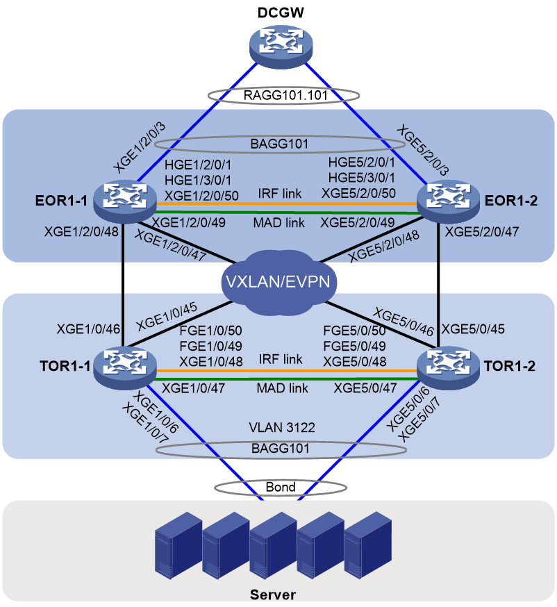
Table 5 Interface and IP address assignment and topology information for devices
|
Device |
Interface |
IP address |
Remarks |
|
TOR (IRF) |
XGE1/0/6 |
N/A |
Connected to a server. |
|
XGE1/0/7 |
N/A |
Connected to a server. |
|
|
XGE1/0/45 |
N/A |
Connected to XGE5/2/0/48 on EOR1-2. |
|
|
XGE1/0/46 |
N/A |
Connected to XGE1/2/0/48 on EOR1-1. |
|
|
XGE1/0/47 |
N/A |
Physical interface used for IRF MAD. |
|
|
XGE1/0/48 |
N/A |
IRF physical interface. |
|
|
FGE1/0/49 |
N/A |
IRF physical interface. |
|
|
FGE1/0/50 |
N/A |
IRF physical interface. |
|
|
XGE5/0/6 |
N/A |
Connected to a server. |
|
|
XGE5/0/7 |
N/A |
Connected to a server. |
|
|
XGE5/0/45 |
N/A |
Connected to XGE5/2/0/47 on EOR1-2. |
|
|
XGE5/0/46 |
N/A |
Connected to XGE1/2/0/47 on EOR1-1. |
|
|
XGE5/0/47 |
N/A |
Physical interface used for IRF MAD. |
|
|
XGE5/0/48 |
N/A |
IRF physical interface. |
|
|
FGE5/0/49 |
N/A |
IRF physical interface. |
|
|
FGE5/0/50 |
N/A |
IRF physical interface. |
|
|
BAGG101 |
N/A |
Connected to servers. |
|
|
Loopback0 |
19.1.37.1/32 |
Used to establish BGP peer relationship with the EOR IRF fabric. |
|
|
VLAN-interface4093 |
member 1: 192.168.2.1/24 member 5: 192.168.2.2/24 |
Used for IRF MAD. |
|
|
EOR (IRF) |
HGE1/2/0/1 |
N/A |
IRF physical interface. |
|
HGE1/3/0/1 |
N/A |
IRF physical interface. |
|
|
XGE1/2/0/3 |
N/A |
Connected to DCGW. |
|
|
XGE1/2/0/47 |
N/A |
Connected to XGE5/0/46 on TOR1-2. |
|
|
XGE1/2/0/48 |
N/A |
Connected to XGE1/0/46 on TOR1-1. |
|
|
XGE1/2/0/49 |
N/A |
Physical interface used for IRF MAD. |
|
|
XGE1/2/0/50 |
N/A |
IRF physical interface. |
|
|
HGE5/2/0/1 |
N/A |
IRF physical interface. |
|
|
HGE5/3/0/1 |
N/A |
IRF physical interface. |
|
|
XGE5/2/0/3 |
N/A |
Connected to DCGW. |
|
|
XGE5/2/0/47 |
N/A |
Connected to XGE5/0/45 on TOR1-2. |
|
|
XGE5/2/0/48 |
N/A |
Connected to XGE1/0/45 on TOR1-1. |
|
|
XGE5/2/0/49 |
N/A |
Physical interface used for IRF MAD. |
|
|
XGE5/2/0/50 |
N/A |
IRF physical interface. |
|
|
BAGG101 |
N/A |
Connected to DCGW. |
|
|
Loopback0 |
19.1.37.3/32 |
Used to establish BGP peer relationship with the TOR IRF fabric. |
|
|
VLAN-interface4093 |
Member 1: 192.168.2.2/24 Member 5: 192.168.2.1/24 |
Used for IRF MAD. |
Major settings before conversion
· TOR:
#
router id 19.1.129.96
#
ospf 100
non-stop-routing
area 0.0.0.0
#
vlan 2 to 4094
#
irf-port 1/1
port group interface FortyGigE 1/0/49
port group interface FortyGigE 1/0/50
port group interface Ten-GigabitEthernet1/0/48
#
irf-port 5/2
port group interface FortyGigE 5/0/49
port group interface FortyGigE 5/0/50
port group interface Ten-GigabitEthernet5/0/48
#
stp global enable
#
l2vpn enable
vxlan tunnel arp-learning disable
#
vsi VSI_30061
arp suppression enable
vxlan 30061
evpn encapsulation vxlan
route-distinguisher auto
vpn-target auto export-extcommunity
vpn-target auto import-extcommunity
#
interface Bridge-Aggregation101
description To_vUP_For_VxLAN-AC
port link-type trunk
undo port trunk permit vlan 1
port trunk permit vlan 3122
link-aggregation mode dynamic
link-aggregation bfd ipv4 source 66.6.6.5 destination 66.6.6.6
vtep access port
bfd min-transmit-interval 100
bfd min-receive-interval 100
bfd detect-multiplier 3
#
service-instance 3122
encapsulation s-vid 3122
xconnect vsi VSI_30061
#
interface LoopBack0
ip address 19.1.37.1 255.255.255.255
#
interface Vlan-interface4093
mad bfd enable
mad ip address 192.168.2.1 255.255.255.0 member 1
mad ip address 192.168.2.2 255.255.255.0 member 5
#
interface Ten-GigabitEthernet1/0/6
port link-mode bridge
description TO_Sever
port link-type trunk
undo port trunk permit vlan 1
port trunk permit vlan 3122
lldp compliance admin-status cdp txrx
vtep access port
port link-aggregation group 101
#
interface Ten-GigabitEthernet1/0/7
port link-mode bridge
description TO_Sever
port link-type trunk
undo port trunk permit vlan 1
port trunk permit vlan 3122
lldp compliance admin-status cdp txrx
vtep access port
port link-aggregation group 101
#
interface Ten-GigabitEthernet1/0/45
port link-mode route
mtu 9000
link-delay down msec 100
link-delay up msec 100
ip address unnumbered interface LoopBack0
ospf network-type p2p
ospf 100 area 0.0.0.0
lldp compliance admin-status cdp txrx
lldp management-address arp-learning
lldp tlv-enable basic-tlv management-address-tlv interface LoopBack0
undo mac-address static source-check enable
#
interface Ten-GigabitEthernet1/0/46
port link-mode route
mtu 9000
link-delay down msec 100
link-delay up msec 100
ip address unnumbered interface LoopBack0
ospf network-type p2p
ospf 100 area 0.0.0.0
lldp compliance admin-status cdp txrx
lldp management-address arp-learning
lldp tlv-enable basic-tlv management-address-tlv interface LoopBack0
undo mac-address static source-check enable
#
interface Ten-GigabitEthernet1/0/47
port link-mode bridge
port access vlan 4093
undo stp enable
undo lldp enable
lldp compliance admin-status cdp txrx
#
interface Ten-GigabitEthernet1/0/48
#
interface FortyGigE 1/0/49
#
interface FortyGigE 1/0/50
#
interface Ten-GigabitEthernet5/0/6
port link-mode bridge
description TO_Sever
port link-type trunk
undo port trunk permit vlan 1
port trunk permit vlan 3122
lldp compliance admin-status cdp txrx
vtep access port
port link-aggregation group 101
#
interface Ten-GigabitEthernet5/0/7
port link-mode bridge
description TO_Sever
port link-type trunk
undo port trunk permit vlan 1
port trunk permit vlan 3122
lldp compliance admin-status cdp txrx
vtep access port
port link-aggregation group 101
#
interface Ten-GigabitEthernet5/0/45
port link-mode route
mtu 9000
link-delay down msec 100
link-delay up msec 100
ip address unnumbered interface LoopBack0
ospf network-type p2p
ospf 100 area 0.0.0.0
lldp compliance admin-status cdp txrx
lldp management-address arp-learning
lldp tlv-enable basic-tlv management-address-tlv interface LoopBack0
undo mac-address static source-check enable
#
interface Ten-GigabitEthernet5/0/46
port link-mode route
mtu 9000
link-delay down msec 100
link-delay up msec 100
ip address unnumbered interface LoopBack0
ospf network-type p2p
ospf 100 area 0.0.0.0
lldp compliance admin-status cdp txrx
lldp management-address arp-learning
lldp tlv-enable basic-tlv management-address-tlv interface LoopBack0
undo mac-address static source-check enable
#
interface Ten-GigabitEthernet5/0/47
port link-mode bridge
port access vlan 4093
undo stp enable
undo lldp enable
lldp compliance admin-status cdp txrx
#
interface Ten-GigabitEthernet5/0/48
#
interface FortyGigE 5/0/49
#
interface FortyGigE 5/0/50
#
bgp 64667
non-stop-routing
peer 19.1.37.3 as-number 64667
peer 19.1.37.3 connect-interface LoopBack0
#
address-family l2vpn evpn
peer 19.1.37.3 enable
#
· EOR:
#
router id 19.1.129.99
#
ospf 100
non-stop-routing
area 0.0.0.0
#
vlan 2 to 4094
#
irf-port 1/1
port group interface hundredgige1/2/0/1 mode enhanced
port group interface hundredgige1/3/0/1 mode enhanced
port group interface Ten-GigabitEthernet1/2/0/50 mode enhanced
#
irf-port 5/2
port group interface hundredgige5/2/0/1 mode enhanced
port group interface hundredgige5/3/0/1 mode enhanced
port group interface Ten-GigabitEthernet5/2/0/50 mode enhanced
#
vsi VSI_30061
arp suppression enable
vxlan 30061
evpn encapsulation vxlan
route-distinguisher auto
vpn-target auto export-extcommunity
vpn-target auto import-extcommunity
#
interface Bridge-Aggregation101
description TO_DCGW
port link-type trunk
undo port trunk permit vlan 1
port trunk permit vlan 101
link-aggregation mode dynamic
#
service-instance 3122
encapsulation s-vid 101
xconnect vsi VSI_30061 access-mode Ethernet
#
interface LoopBack0
ip address 19.1.37.3 255.255.255.255
#
interface Vlan-interface4093
mad bfd enable
mad ip address 192.168.2.2 255.255.255.0 member 1
mad ip address 192.168.2.1 255.255.255.0 member 5
#
interface hundredgige1/2/0/1
#
interface hundredgige1/3/0/1
#
interface Ten-GigabitEthernet1/2/0/3
port link-mode bridge
port link-type trunk
undo port trunk permit vlan 1
port trunk permit vlan 101 104 to 106
port link-aggregation group 101
#
interface Ten-GigabitEthernet1/2/0/47
port link-mode route
mtu 9000
dampening
ip address unnumbered interface LoopBack0
ospf network-type p2p
ospf 100 area 0.0.0.0
lldp management-address arp-learning
lldp tlv-enable basic-tlv management-address-tlv interface LoopBack0
#
interface Ten-GigabitEthernet1/2/0/48
port link-mode route
mtu 9000
dampening
ip address unnumbered interface LoopBack0
ospf network-type p2p
ospf 100 area 0.0.0.0
lldp management-address arp-learning
lldp tlv-enable basic-tlv management-address-tlv interface LoopBack0
#
interface Ten-GigabitEthernet1/2/0/49
port link-mode bridge
port access vlan 4093
undo stp enable
#
interface Ten-GigabitEthernet1/2/0/50
#
interface hundredgige5/2/0/1
#
interface hundredgige5/3/0/1
#
interface Ten-GigabitEthernet5/2/0/3
port link-mode bridge
port link-type trunk
undo port trunk permit vlan 1
port trunk permit vlan 101 104 to 106
port link-aggregation group 101
#
interface Ten-GigabitEthernet5/2/0/47
port link-mode route
mtu 9000
dampening
ip address unnumbered interface LoopBack0
ospf network-type p2p
ospf 100 area 0.0.0.0
lldp management-address arp-learning
lldp tlv-enable basic-tlv management-address-tlv interface LoopBack0
#
interface Ten-GigabitEthernet5/2/0/48
port link-mode route
mtu 9000
dampening
ip address unnumbered interface LoopBack0
ospf network-type p2p
ospf 100 area 0.0.0.0
lldp management-address arp-learning
lldp tlv-enable basic-tlv management-address-tlv interface LoopBack0
#
interface Ten-GigabitEthernet5/2/0/49
port link-mode bridge
port access vlan 4093
undo stp enable
#
interface Ten-GigabitEthernet5/2/0/50
#
bgp 64667
non-stop-routing
group evpn internal
peer evpn connect-interface LoopBack0
peer 19.1.37.1 group evpn
#
address-family l2vpn evpn
undo policy vpn-target
peer evpn enable
peer evpn next-hop-local
peer evpn reflect-client
#
· DCGW:
interface Route-Aggregation101.101
description ToCP_For_CU-Tunnel
ip binding vpn-instance CP2UP_L3VPN
ip address 19.1.15.9 255.255.255.248
vlan-type dot1q vid 101
bfd min-echo-receive-interval 50
bfd detect-multiplier 8
#
Network after conversion
Conversion key points and network description
Settings for IRF fabric to M-LAG system conversion
Change the network scheme of TOR devices and EOR devices from IRF network to M-LAG system network.
For a modular device, you must execute the undo chassis convert mode command to convert the device operating mode from IRF to standalone before configuring M-LAG settings. To avoid configuration loss because of mode conversion, save the running configuration to a configuration file before mode conversion. After mode conversion, save the running configuration to another configuration file. Then, compare the two configuration files to ensure that no settings are lost.
Typically, convert the IRF physical interfaces to physical interfaces attached to the peer link and convert the physical interfaces used for IRF MAD to physical interfaces attached to the keepalive link. In this example, XGE 1/0/48 and XGE 5/0/48 on the TOR devices and XGE 1/2/0/50 and XGE 5/2/0/50 on the EOR devices are IRF physical interfaces before IRF fabric to M-LAG system conversion. Because all member ports for the peer-link interface must operate at the same rate and to enhance the high availability of the keepalive link, convert these interfaces to physical interfaces attached to the keepalive link.
On the TOR devices, convert the multichassis aggregate interface connected to servers to an M-LAG interface. On the EOR devices, convert the multichassis aggregate interface connected to DCGW to an M-LAG interface.
After an IRF fabric is converted to an M-LAG system, the two member devices run independently. They have the same IP addresses for Layer 3 interfaces. To remove IP address conflicts, you must reconfigure IP addresses for the interfaces.
To use dynamic routing for interconnection between M-LAG member devices and upstream devices, the M-LAG primary and secondary member devices must have Layer 3 connectivity and have routes to reach each other. This configuration is used to protect services in case of uplink failure and M-LAG system failure.
Because the IRF fabrics are configured with dynamic routing settings, route ID conflicts occur after the IRF fabrics are converted to M-LAG systems. To resolve the issue, specify a new router ID for the routing process on one of the devices in each M-LAG system and restart the routing process.
EVPN VXLAN settings
Before conversion, an IRF fabric acts as one VTEP. To convert an IRF fabric to an M-LAG system, enable EVPN M-LAG and specify the same virtual VTEP address on both the member devices. To specify a virtual VTEP address, use the evpn m-lag group command. Each M-LAG member device in an M-LAG system uses the virtual VTEP address as the source address to automatically set up VXLAN tunnels with remote VTEPs to avoid single points of failure.
For S12500X-AF and S12500F-AF switches, you must use the l2vpn m-lag peer-link tunnel command to enable each M-LAG member device to automatically set up a VXLAN tunnel with the peer M-LAG member device. With this command, the two VTEPs in an M-LAG system will automatically set up a VXLAN tunnel between them and associate the VXLAN tunnel with all VXLANs. When a site-facing AC on one M-LAG member device fails, the device forwards the packets from a remote VTEP (not an M-LAG member in the same M-LAG system) and destined for the AC to the other M-LAG member device over the automatically created VXLAN tunnel. The packets are encapsulated with the VXLAN ID associated with the VSI of the failed site-facing AC. When the other M-LAG member device receives the packets, it decapsulates them and forwards them in the VSI where they belong. Because Layer 3 forwarding is performed over VXLAN tunnels, you must use the vxlan ip-forwarding command to enable Layer 3 forwarding for VXLAN tunnels.
For S12500G-AF, S12500-XS, S10500X, S7600, S7600E-X, and S7500X switches, you must enable each M-LAG member device to create frame match criteria based on VXLAN IDs for the dynamic ACs on the direct peer link. For this purpose, use the l2vpn m-lag peer-link ac-match-rule vxlan-mapping command.
Operation order
Make sure the OSPF and BGP protocols come up on the EOR and TOR devices and tunnels are established among them before traffic is switched over from one device to another device. This order ensures fast traffic switchover when interfaces are brought up. For this purpose, convert the EOR and TOR IRF subordinate devices together to M-LAG member devices and convert the EOR and TOR IRF master devices together to M-LAG member devices.
The conversion operations are as follows:
1. Manually shut down all service interfaces on the EOR IRF subordinate device and TOR IRF subordinate device to switch over traffic to the EOR IRF master device and TOR IRF master device, respectively. Then, shut down IRF physical interfaces on the IRF master devices to lead in IRF splits.
2. Configure M-LAG settings on the EOR IRF subordinate device and TOR IRF subordinate device.
3. Bring up the interfaces that have been shut down on the EOR IRF subordinate device and TOR IRF subordinate device and the interfaces connected to the subordinate devices on the master devices. Manually shut down all service interfaces on the EOR IRF master device and TOR IRF master device to switch over service traffic to the EOR IRF subordinate device and TOR IRF subordinate device.
4. Configure M-LAG settings on the EOR IRF master device and TOR IRF master device.
5. Manually bring up the interfaces that have been shut down on the EOR IRF master device and TOR IRF master device to complete M-LAG system setup. Traffic will be distributed to both the member devices in each M-LAG system.
Network diagram
Figure 6 Network diagram (after conversion)
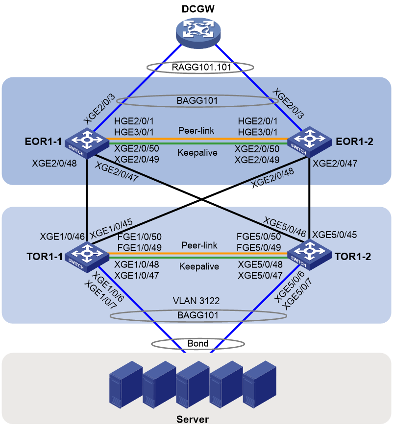
Table 6 Interface and IP address assignment and topology information for devices
|
Device |
Interface |
IP address |
Remarks |
|
TOR1-1 |
XGE1/0/6 |
N/A |
Connected to a server. |
|
XGE1/0/7 |
N/A |
Connected to a server. |
|
|
XGE1/0/45 |
N/A |
Connected to XGE2/0/48 on EOR1-2. |
|
|
XGE1/0/46 |
N/A |
Connected to XGE2/0/48 on EOR1-1. |
|
|
XGE1/0/47 |
N/A |
Physical interface attached to the keepalive link. Connected to XGE5/0/47 on TOR1-2. |
|
|
XGE1/0/48 |
N/A |
Physical interface attached to the keepalive link. Connected to XGE5/0/48 on TOR1-2. |
|
|
FGE1/0/49 |
N/A |
Physical interface attached to the peer link. Connected to FGE5/0/49 on TOR1-2. |
|
|
FGE1/0/50 |
N/A |
Physical interface attached to the peer link. Connected to FGE5/0/50 on TOR1-2. |
|
|
BAGG1 |
N/A |
Layer 2 aggregate interface attached to the peer link. |
|
|
BAGG101 |
N/A |
Connected to servers. |
|
|
RAGG1 |
1.1.1.1/24 |
Layer 3 aggregate interface attached to the keepalive link. |
|
|
Loopback0 |
19.1.37.3 |
Local address. |
|
|
Loopback2 |
19.1.37.6 |
Virtual VTEP address. |
|
|
VLAN-interface4094 |
192.168.1.1/30 |
Used for OSPF neighbor relationship establishment over the peer link. |
|
|
TOR1-2 |
XGE5/0/6 |
N/A |
Connected to a server. |
|
XGE5/0/7 |
N/A |
Connected to a server. |
|
|
XGE5/0/45 |
N/A |
Connected to XGE2/0/47 on EOR1-2. |
|
|
XGE5/0/46 |
N/A |
Connected to XGE2/0/47 on EOR1-1. |
|
|
XGE5/0/47 |
N/A |
Physical interface attached to the keepalive link. Connected to XGE1/0/47 on TOR1-1. |
|
|
XGE5/0/48 |
N/A |
Physical interface attached to the keepalive link. Connected to XGE1/0/48 on TOR1-1. |
|
|
FGE5/0/49 |
N/A |
Physical interface attached to the peer link. Connected to XGE1/0/49 on TOR1-1. |
|
|
FGE5/0/50 |
N/A |
Physical interface attached to the peer link. Connected to XGE1/0/50 on TOR1-1. |
|
|
BAGG1 |
N/A |
Layer 2 aggregate interface attached to the peer link. |
|
|
BAGG101 |
N/A |
Connected to servers. |
|
|
RAGG1 |
1.1.1.2/24 |
Layer 3 aggregate interface attached to the keepalive link. |
|
|
Loopback0 |
19.1.37.4 |
Local address. |
|
|
Loopback2 |
19.1.37.6 |
Virtual VTEP address. |
|
|
VLAN-interface4094 |
192.168.1.2/30 |
Used for OSPF neighbor relationship establishment over the peer link. |
|
|
EOR1-1 |
HGE2/0/1 |
N/A |
Physical interface attached to the peer link. Connected to HGE2/0/1 on EOR1-2. |
|
HGE3/0/1 |
N/A |
Physical interface attached to the peer link. Connected to HGE3/0/1 on EOR1-2. |
|
|
XGE2/0/3 |
N/A |
Connected to DCGW. |
|
|
XGE2/0/47 |
N/A |
Connected to XGE5/0/46 on TOR1-2. |
|
|
XGE2/0/48 |
N/A |
Connected to XGE1/0/46 on TOR1-2. |
|
|
XGE2/0/49 |
N/A |
Physical interface attached to the keepalive link. Connected to XGE2/0/49 on EOR1-2. |
|
|
XGE2/0/50 |
N/A |
Physical interface attached to the keepalive link. Connected to XGE2/0/50 on EOR1-2. |
|
|
BAGG1 |
N/A |
Layer 2 aggregate interface attached to the peer link. |
|
|
RAGG1 |
1.1.1.1/24 |
Layer 3 aggregate interface attached to the keepalive link. |
|
|
BAGG101 |
N/A |
Connected to DCGW. |
|
|
Loopback0 |
19.1.37.1 |
Local address. |
|
|
Loopback2 |
19.1.37.5 |
Virtual VTEP address. |
|
|
VLAN-interface4094 |
192.168.2.5/30 |
Used for OSPF neighbor relationship establishment over the peer link. |
|
|
EOR1-2 |
HGE2/0/1 |
N/A |
Physical interface attached to the peer link. Connected to HGE2/0/1 on EOR1-1. |
|
HGE3/0/1 |
N/A |
Physical interface attached to the peer link. Connected to HGE3/0/1 on EOR1-1. |
|
|
XGE2/0/3 |
N/A |
Connected to DCGW. |
|
|
XGE2/0/47 |
N/A |
Connected to XGE5/0/45 on TOR1-2. |
|
|
XGE2/0/48 |
N/A |
Connected to XGE1/0/45 on TOR1-1. |
|
|
XGE2/0/49 |
N/A |
Physical interface attached to the keepalive link. Connected to XGE2/0/49 on EOR1-1. |
|
|
XGE2/0/50 |
N/A |
Physical interface attached to the keepalive link. Connected to XGE2/0/50 on EOR1-1. |
|
|
BAGG1 |
N/A |
Layer 2 aggregate interface attached to the peer link. |
|
|
RAGG1 |
1.1.1.2/24 |
Layer 3 aggregate interface attached to the keepalive link. |
|
|
BAGG101 |
N/A |
Connected to DCGW. |
|
|
Loopback0 |
19.1.37.2 |
Loopback interface for real VTEP address. |
|
|
Loopback2 |
19.1.37.5 |
Loopback interface for virtual VTEP address. |
|
|
VLAN-interface4094 |
192.168.2.6/30 |
Used for OSPF neighbor relationship establishment over the peer link. |
Converting the TOR and EOR IRF subordinate devices from IRF member devices to M-LAG member devices
In this example, the TOR IRF subordinate device is TOR1-2 and the EOR IRF subordinate device is EOR1-2.
Configuration summary
3. Converting the operating mode of the EOR IRF subordinate device from IRF mode to standalone mode
4. Configuring M-LAG settings on the TOR IRF subordinate device
5. Configuring M-LAG settings on the EOR IRF subordinate device
6. Verifying the configuration on TOR1-2
7. Verifying the configuration on EOR1-2
Restrictions and guidelines
· As a best practice, prepare the settings in advance and quickly deploy the settings to reduce convergence time.
· Strictly follow the steps used to isolate the IRF subordinate device in an IRF fabric to avoid the subordinate device being placed in Recovery state by MAD. Packet loss might occur when you bring up and shut down interfaces. Make sure you are fully aware of the operation on the network.
· After you specify a new router ID for an OSPF process, you must restart the OSPF process for the router ID to take effect.
· As a best practice to establish VXLAN tunnels in advance and reduce network convergence time, bring up the Layer 3 interfaces that connect the TOR and EOR IRF subordinate devices after traffic is switched over to the TOR and EOR IRF master devices.
· As a best practice, configure the IRF master device as the M-LAG secondary device and the IRF subordinate device as the M-LAG primary device. If you do not do so, the effective roles of the member devices might be inconsistent with those configured for the member devices after the M-LAG system is set up. In this case, role switchover might occur. Packets will be lost for about 50 seconds during the role switchover.
Shutting down service physical interfaces on the TOR IRF subordinate device to switch over traffic to the IRF master device and splitting the TOR IRF fabric
# On TOR1-2, shut down all physical interfaces except IRF physical interfaces to switch over traffic to TOR1-1.
[TOR1-2] interface range ten-gigabitethernet 5/0/6 ten-gigabitethernet 5/0/7 ten-gigabitethernet 5/0/45 to ten-gigabitethernet 5/0/47
[TOR1-2-if-range] shutdown
[TOR1-2-if-range] quit
# On TOR1-1, shut down IRF physical interfaces to split the IRF fabric.
[TOR1-1] interface range ten-gigabitethernet 1/0/48 fortygige 1/0/49 fortygige 1/0/50
[TOR1-1-if-range] shutdown
[TOR1-1-if-range] quit
Shutting down service physical interfaces on the EOR IRF subordinate device to switch over traffic to the IRF master device and splitting the EOR IRF fabric
1. On EOR1-2, shut down all physical interfaces except IRF physical interfaces to switch over traffic to EOR1-1.
[EOR1-2] interface range ten-gigabitethernet 5/2/0/3 ten-gigabitethernet 5/2/0/47 to ten-gigabitethernet 5/2/0/49
[EOR1-2-if-range] shutdown
[EOR1-2-if-range] quit
2. On EOR1-1, shut down IRF physical interfaces to split the IRF fabric.
[EOR1-1] interface range hundredgige 1/2/0/1 hundredgige 1/3/0/1 ten-gigabitethernet 1/2/0/50
[EOR1-1-if-range] shutdown
[EOR1-1-if-range] quit
3. Bring up the Layer 3 interfaces that connect TOR1-2 and EOR1-2:
# On TOR1-2, bring up the Layer 3 interface connected to EOR1-2.
[TOR1-2] interface ten-gigabitethernet 5/0/45
[TOR1-2-Ten-GigabitEthernet5/0/45] undo shutdown
[TOR1-2-Ten-GigabitEthernet5/0/45] quit
# On EOR 1-2, bring up the Layer 3 interface connected to TOR 1-2.
[EOR1-2] interface ten-gigabitethernet 5/2/0/47
[EOR1-2-Ten-GigabitEthernet5/2/0/47] undo shutdown
[EOR1-2-Ten-GigabitEthernet5/2/0/47] quit
Converting the operating mode of the EOR IRF subordinate device from IRF mode to standalone mode
# Save the running configuration in IRF mode to file irf.cfg.
[EOR1-2] save flash:/irf.cfg
The current configuration will be saved to flash:/irf.cfg. Continue? [Y/N]:y
Now saving current configuration to the device.
Saving configuration flash:/irf.cfg.Please wait...
Configuration is saved to device successfully.
# Convert the operating mode of the EOR IRF subordinate device from IRF mode to standalone mode.
[EOR1-2] undo chassis convert mode
The device will switch to stand-alone mode and reboot. Continue? [Y/N]:y
You are recommended to save the current running configuration and specify the configuration file for the next startup. Continue? [Y/N]:y
Please input the file name(*.cfg)[flash:/startup.cfg]
(To leave the existing filename unchanged, press the enter key):
flash:/startup.cfg exists, overwrite? [Y/N]:y
Validating file. Please wait...
Saved the current configuration to mainboard device successfully.
Do you want to convert the content of the next startup configuration file flash:/startup.cfg to make it available in stand-alone mode? [Y/N]:y
Now rebooting, please wait...
# Compare file startup.cfg (the configuration file in standalone mode) with file irf.cfg (the configuration file in IRF mode) to ensure that no settings are lost.
[EOR1-2] display diff configfile flash:/irf.cfg configfile flash:/startup.cfg
Configuring M-LAG settings on the TOR IRF subordinate device
1. The member devices might use the same MAC address after the IRF fabric splits, which causes MAC address conflict. To avoid network issues caused by MAC address conflict, configure the IRF fabric to remove the specified IRF bridge MAC address (if any) and not retain its bridge MAC address after it splits:
# Configure the IRF fabric to change its bridge MAC address as soon as the address owner leaves.
[TOR1-2] undo irf mac-address persistent
# Restore the default IRF bridge MAC address.
[TOR1-2] undo irf mac-address
2. Configure M-LAG system settings:
# Set the data restoration interval to 300 seconds.
[TOR1-2] m-lag restore-delay 300
# Set the M-LAG role priority of the device.
[TOR1-2] m-lag role priority 100
# Configure the M-LAG system MAC address. For the M-LAG member devices to be identified as one M-LAG system, you must configure the same M-LAG system MAC address on them.
[TOR1-2] m-lag system-mac 0002-0002-0002
# Set the M-LAG system number. You must assign different M-LAG system numbers to the M-LAG member devices in an M-LAG system.
[TOR1-2] m-lag system-number 2
# Set the M-LAG system priority. You must configure the same M-LAG system priority for the M-LAG member devices in an M-LAG system.
[TOR1-2] m-lag system-priority 123
# Specify the destination and source IPv4 addresses of keepalive packets as 1.1.1.1 and 1.1.1.2, respectively.
[TOR1-2] m-lag keepalive ip destination 1.1.1.1 source 1.1.1.2
# Enable M-LAG system auto-recovery and set the reload delay timer. By default, if only one M-LAG member device starts up in an M-LAG system, that M-LAG member device will be stuck in the None role with all its M-LAG interfaces being M-LAG DOWN after it starts up. The M-LAG interfaces cannot forward service traffic. To resolve this issue, perform this task.
[TOR1-2] m-lag auto-recovery reload-delay 240
# Enable EVPN M-LAG and specify the virtual VTEP address.
[TOR1-2] evpn m-lag group 19.1.37.6
3. Configure an M-LAG interface:
# Assign Layer 2 aggregate interface 101 (the interface connected to servers) to an M-LAG group. Disable spanning tree on the M-LAG interface.
[TOR1-2] interface Bridge-Aggregation 101
[TOR1-2-Bridge-Aggregation101] port m-lag group 101
[TOR1-2-Bridge-Aggregation101] undo stp enable
[TOR1-2-Bridge-Aggregation101] quit
4. Configure the peer link:
# Create Layer 2 aggregate interface 1. The interface will be used as the peer-link interface.
[TOR1-2] interface bridge-aggregation 1
[TOR1-2-Bridge-Aggregation1] quit
# Remove IRF physical interfaces Ten-GigabitEthernet 5/0/48, FortyGigE 5/0/49, and FortyGigE 5/0/50 from IRF-port 5/2 and assign interfaces FortyGigE 5/0/49 and FortyGigE 5/0/50 to aggregation group 1. The physical interfaces assigned to the aggregation group will be attached to the peer link.
[TOR1-2] interface range ten-gigabitethernet 5/0/48 fortygige 5/0/49 fortygige 5/0/50
[TOR1-2-if-range] shutdown
[TOR1-2-if-range] quit
[TOR1-2] irf-port 5/2
[TOR1-2-irf-port5/2] undo port group interface fortygige 5/0/49
[TOR1-2-irf-port5/2] undo port group interface fortygige 5/0/50
[TOR1-2-irf-port5/2] undo port group interface ten-gigabitethernet 5/0/48
[TOR1-2-irf-port5/2] quit
[TOR1-2] interface range fortygige 5/0/49 fortygige 5/0/50
[TOR1-2-if-range] port link-aggregation group 1
[TOR1-2-if-range] quit
# Configure Layer 2 aggregate interface 1 as the peer-link interface.
[TOR1-2] interface Bridge-Aggregation 1
[TOR1-2-Bridge-Aggregation1] port link-type trunk
[TOR1-2-Bridge-Aggregation1] port trunk permit vlan all
[TOR1-2-Bridge-Aggregation1] link-aggregation mode dynamic
[TOR1-2-Bridge-Aggregation1] port m-lag peer-link 1
[TOR1-2-Bridge-Aggregation1] quit
5. Configure the interfaces attached to the keepalive link:
# Remove VLAN-interface 4093 used for IRF MAD and create Layer 3 aggregate interface 1. The aggregate interface will be attached to the keepalive link.
[TOR1-2] undo interface vlan-interface 4093
[TOR1-2] interface route-aggregation 1
[TOR1-2-Route-Aggregation1] quit
# Assign interfaces Ten-GigabitEthernet 5/0/47 and Ten-GigabitEthernet 5/0/48 to Layer 3 aggregation group 1. The physical interfaces will be attached to the keepalive link.
[TOR1-2] interface range ten-gigabitethernet 5/0/47 ten-gigabitethernet 5/0/48
[TOR1-2-if-range] port link-mode route
[TOR1-2-if-range] port link-aggregation group 1
[TOR1-2-if-range] quit
# Configure Layer 3 aggregation group 1 to operate in dynamic aggregation mode and assign an IP address to the aggregate interface.
[TOR1-2] interface route-aggregation 1
[TOR1-2-Route-Aggregation1] link-aggregation mode dynamic
[TOR1-2-Route-Aggregation1] ip address 1.1.1.2 255.255.255.0
[TOR1-2-Route-Aggregation1] quit
6. Configure the device to establish OSPF neighbor relationship with the peer member device over the peer link.
[TOR1-2] interface vlan-interface 4094
[TOR1-2-Vlan-interface4094] ip address 192.168.1.2 255.255.255.252
[TOR1-2-Vlan-interface4094] ospf 100 area 0.0.0.0
[TOR1-2-Vlan-interface4094] quit
7. Remove the settings used by the original IRF fabric to establish BGP peer relationship with the EOR IRF fabric and reconfigure TOR1-2 to establish BGP peer relationship with EOR1-1 and EOR1-2.
[TOR1-2] bgp 64667
[TOR1-2-bgp-default] undo peer 19.1.37.3
[TOR1-2-bgp-default] group evpn internal
[TOR1-2-bgp-default] peer evpn connect-interface LoopBack0
[TOR1-2-bgp-default] peer 19.1.37.1 group evpn
[TOR1-2-bgp-default] peer 19.1.37.2 group evpn
[TOR1-2-bgp-default] address-family l2vpn evpn
[TOR1-2-bgp-default-evpn] peer evpn enable
[TOR1-2-bgp-default-evpn] quit
[TOR1-2-bgp-default] quit
8. Reconfigure IP addresses for interfaces:
|
|
NOTE: After the TOR IRF fabric is converted to an M-LAG system, make sure each Layer 3 interface has a unique IP address on the two member devices. You must reconfigure IP addresses for these interfaces on the member devices. |
# On TOR1-2, change the IP address of Loopback 0 to 19.1.37.4. The device uses this IP address to establish routing neighbor relationship with other devices on the underlay network. The two member devices in an M-LAG system must use different IP addresses to establish routing neighbor relationship with other devices.
[TOR1-2] interface loopback 0
[TOR1-2-LoopBack0] ip address 19.1.37.4 255.255.255.255
[TOR1-2-LoopBack0] ospf 100 area 0.0.0.0
[TOR1-2-LoopBack0] quit
# On TOR1-2, change the IP address of Loopback 2 to 19.1.37.6. You must specify the same IP address for the two member devices in an M-LAG system to ensure that the M-LAG system can automatically establish VXLAN tunnels with remote VTEPs. The specified IP address is the virtual VTEP address configured by using the evpn m-lag group command.
[TOR1-2] interface loopback 2
[TOR1-2-LoopBack2] ip address 19.1.37.6 255.255.255.255
[TOR1-2-LoopBack2] ospf 100 area 0.0.0.0
[TOR1-2-LoopBack2] quit
# On TOR1-2, change the router ID and restart the OSPF process.
[TOR1-2] router-id 19.1.35.4
<TOR1-2> quit
<TOR1-2> reset ospf process? [Y/N]:y
9. Add interfaces to the user-configured list of excluded ports, which will not be shut down by M-LAG MAD when the M-LAG system splits.
<TOR1-2> system-view
[TOR1-2] m-lag mad exclude interface route-aggregation 1
[TOR1-2] m-lag mad exclude interface ten-gigabitethernet 5/0/47
[TOR1-2] m-lag mad exclude interface ten-gigabitethernet 5/0/48
[TOR1-2] m-lag mad exclude interface loopback 0
[TOR1-2] m-lag mad exclude interface loopback 2
[TOR1-2] m-lag mad exclude interface vlan-interface 4094
Configuring M-LAG settings on the EOR IRF subordinate device
1. The member devices might use the same MAC address after the IRF fabric splits, which causes MAC address conflict. To avoid network issues caused by MAC address conflict, configure the IRF fabric to remove the specified IRF bridge MAC address (if any) and not retain its bridge MAC address after it splits:
# Configure the IRF fabric to change its bridge MAC address as soon as the address owner leaves.
[EOR1-2] undo irf mac-address persistent
# Restore the default IRF bridge MAC address.
[EOR1-2] undo irf mac-address
2. Configure M-LAG system settings:
# Set the data restoration interval to 300 seconds.
[EOR1-2] m-lag restore-delay 300
# Set the M-LAG role priority of the device.
[EOR1-2] m-lag role priority 100
# Configure the M-LAG system MAC address. For the M-LAG member devices to be identified as one M-LAG system, you must configure the same M-LAG system MAC address on them.
[EOR1-2] m-lag system-mac 0001-0001-0001
# Set the M-LAG system number. You must assign different M-LAG system numbers to the M-LAG member devices in an M-LAG system.
[EOR1-2] m-lag system-number 2
# Set the M-LAG system priority. You must configure the same M-LAG system priority for the M-LAG member devices in an M-LAG system.
[EOR1-2] m-lag system-priority 123
# Specify the destination and source IPv4 addresses of keepalive packets as 1.1.1.1 and 1.1.1.2, respectively.
[EOR1-2] m-lag keepalive ip destination 1.1.1.1 source 1.1.1.2
# Enable M-LAG system auto-recovery and set the reload delay timer. By default, if only one M-LAG member device starts up in an M-LAG system, that M-LAG member device will be stuck in the None role with all its M-LAG interfaces being M-LAG DOWN after it starts up. The M-LAG interfaces cannot forward service traffic. To resolve this issue, perform this task.
[EOR1-2] m-lag auto-recovery reload-delay 240
# Enable EVPN M-LAG and specify the virtual VTEP address.
[EOR1-2] evpn m-lag group 19.1.37.5
3. Enable the member device to automatically set up a VXLAN tunnel with the peer member device, and enable Layer 3 forwarding for all VXLANs. (Applicable only to S12500X-AF and S12500F-AF switches.)
[EOR1-2] l2vpn m-lag peer-link tunnel source 19.1.37.2 destination 19.1.37.1
[EOR1-2] vxlan ip-forwarding tagged
4. Enable the device to create frame match criteria based on VXLAN IDs for the dynamic ACs on the direct peer link. (Applicable only to S12500G-AF, S12500-XS, S10500X, S7600, S7600E-X, and S7500X switches.)
[EOR1-2] l2vpn m-lag peer-link ac-match-rule vxlan-mapping
5. Configure an M-LAG interface:
# Assign Layer 2 aggregate interface 101 (the interface connected to DCGW) to an M-LAG group. Disable spanning tree on the M-LAG interface.
[EOR1-2] interface bridge-aggregation 101
[EOR1-2-Bridge-Aggregation101] port m-lag group 101
[EOR1-2-Bridge-Aggregation101] undo stp enable
[EOR1-2-Bridge-Aggregation101] quit
6. Configure the peer link:
# Create Layer 2 aggregate interface 1. The aggregate interface will be used as the peer-link interface.
[EOR1-2] interface bridge-aggregation 1
[EOR1-2-Bridge-Aggregation1] undo shutdown
# Remove Ten-GigabitEthernet 2/0/50, HundredGigE 2/0/1, and HundredGigE 3/0/1 from IRF-port 5/2. Assign interfaces HundredGigE 2/0/1 and HundredGigE 3/0/1 to aggregation group 1. The physical interfaces assigned to the aggregation group will be attached to the peer link.
[EOR1-2] interface range hundredgige 2/0/1 hundredgige 3/0/1 ten-gigabitethernet 2/0/50
[EOR1-2-if-range] shutdown
[EOR1-2-if-range] quit
[EOR1-2] irf-port 5/2
[EOR1-2-irf-port5/2] undo port group interface hundredgige 2/0/1
[EOR1-2-irf-port5/2] undo port group interface hundredgige 3/0/1
[EOR1-2-irf-port5/2] undo port group interface ten-gigabitethernet 2/0/50
[EOR1-2-irf-port5/2] quit
[EOR1-2] interface range hundredgige 2/0/1 hundredgige 3/0/1
[EOR1-2-if-range] port link-aggregation group 1
[EOR1-2-if-range] quit
# Configure Layer 2 aggregate interface 1 as the peer-link interface.
[EOR1-2] interface Bridge-Aggregation 1
[EOR1-2-Bridge-Aggregation1] port link-type trunk
[EOR1-2-Bridge-Aggregation1] port trunk permit vlan all
[EOR1-2-Bridge-Aggregation1] link-aggregation mode dynamic
[EOR1-2-Bridge-Aggregation1] port m-lag peer-link 1
[EOR1-2-Bridge-Aggregation1] quit
7. Configure the interfaces attached to the keepalive link:
# Create Layer 3 aggregate interface 1. The aggregate interface will be attached to the keepalive link.
[EOR1-2] undo interface vlan-interface 4093
[EOR1-2] interface route-aggregation 1
[EOR1-2-Route-Aggregation1] undo shutdown
[EOR1-2-Route-Aggregation1] quit
# Assign interfaces Ten-GigabitEthernet 2/0/49 and Ten-GigabitEthernet 2/0/50 to Layer 3 aggregation group 1. The physical interfaces will be attached to the keepalive link.
[EOR1-2] interface range ten-gigabitethernet 2/0/49 ten-gigabitethernet 2/0/50
[EOR1-2-if-range] port link-mode route
[EOR1-2-if-range] port link-aggregation group 1
[EOR1-2-if-range] quit
# Configure Layer 3 aggregation group 1 to operate in dynamic aggregation mode and assign an IP address to the aggregate interface.
[EOR1-2] interface route-aggregation 1
[EOR1-2-Route-Aggregation1] link-aggregation mode dynamic
[EOR1-2-Route-Aggregation1] ip address 1.1.1.2 255.255.255.0
[EOR1-2-Route-Aggregation1] quit
8. Configure the device to establish OSPF neighbor relationship with the peer member device over the peer link.
[EOR1-2] interface vlan-interface 4094
[EOR1-2-Vlan-interface4094] undo shutdown
[EOR1-2-Vlan-interface4094] ip address 192.168.2.6 255.255.255.252
[EOR1-2-Vlan-interface4094] ospf 100 area 0.0.0.0
[EOR1-2-Vlan-interface4094] quit
9. Remove the settings used by the original IRF fabric to establish BGP peer relationship with the TOR IRF fabric and reconfigure EOR1-2 to establish BGP peer relationship with TOR1-1 and TOR1-2.
[EOR1-2] bgp 64667
[EOR1-2-bgp-default] undo peer 19.1.37.1
[EOR1-2-bgp-default] peer evpn connect-interface loopback 0
[EOR1-2-bgp-default] peer 19.1.37.3 group evpn
[EOR1-2-bgp-default] peer 19.1.37.4 group evpn
[EOR1-2-bgp-default] quit
10. Reconfigure IP addresses for interfaces:
|
|
NOTE: After the EOR IRF fabric is converted to an M-LAG system, make sure each Layer 3 interface has a unique IP address on the two member devices. You must reconfigure IP addresses for these interfaces on the member devices. |
# On EOR1-2, change the IP address of Loopback 0 to 19.1.37.2. The device uses this IP address to establish routing neighbor relationship with other devices on the underlay network. The two member devices in an M-LAG system must use different IP addresses to establish routing neighbor relationship with other devices.
[EOR1-2] interface loopback 0
[EOR1-2-LoopBack0] ip address 19.1.37.2 255.255.255.255
[EOR1-2-LoopBack0] ospf 100 area 0.0.0.0
[EOR1-2-LoopBack0] quit
# On EOR1-2, change the IP address of Loopback 2 to 19.1.37.5. You must specify the same IP address for the two member devices in an M-LAG system to ensure that the M-LAG system can automatically establish VXLAN tunnels with remote VTEPs. The specified IP address is the virtual VTEP address configured by using the evpn m-lag group command.
[EOR1-2] interface loopback 2
[EOR1-2-LoopBack2] ip address 19.1.37.5 255.255.255.255
[EOR1-2-LoopBack2] ospf 100 area 0.0.0.0
[EOR1-2-LoopBack2] quit
# On EOR1-2, change the router ID and restart the OSPF process.
[EOR1-2] router-id 19.1.35.2
[EOR1-2] quit
<EOR1-2> reset ospf process? [Y/N]:y
11. Add interfaces to the user-configured list of excluded ports, which will not be shut down by M-LAG MAD when the M-LAG system splits.
<EOR1-2> system-view
[EOR1-2] m-lag mad exclude interface route-aggregation 1
[EOR1-2] m-lag mad exclude interface ten-gigabitethernet 5/2/0/49
[EOR1-2] m-lag mad exclude interface ten-gigabitethernet 5/2/0/50
[EOR1-2] m-lag mad exclude interface loopback 0
[EOR1-2] m-lag mad exclude interface loopback 2
[EOR1-2] m-lag mad exclude interface Vlan-interface4094
Verifying the configuration on TOR1-2
# On TOR1-2, display summary information about the peer-link interface and M-LAG interfaces. Verify that the peer-link interface and M-LAG interfaces have been created and they are in down state.
[TOR1-2] display m-lag summary
Global consistency check : -
Inconsistent type 1 global settings: -
Peer-link interface Peer-link interface ID State
BAGG1 1 DOWN
M-LAG IF M-LAG group ID State Check result Type 1 inconsistency
BAGG101 101 DOWN - -
# Verify that TOR1-2 has established OSPF neighbor relationship and BGP peer relationship with EOR1-2.
[TOR1-2] display ospf peer
OSPF Process 100 with Router ID 19.1.35.4
Neighbor Brief Information
Area: 0.0.0.0
Router ID Address Pri Dead-Time State Interface
19.1.35.2 19.1.37.2 1 35 Full/ - FGE5/0/53
[TOR1-2] display bgp peer l2vpn evpn
BGP local router ID: 19.1.129.96
Local AS number: 64667
Total number of peers: 2 Peers in established state: 1
* - Dynamically created peer
Peer AS MsgRcvd MsgSent OutQ PrefRcv Up/Down State
19.1.37.1 64667 1 1 0 0 00:40:54 Connect
19.1.37.2 64667 29 26 0 2 00:17:59 Established
# Verify that a tunnel has been established between TOR1-2 and EOR1-2 and the tunnel is in up state.
[TOR1-2] display interface Tunnel
Tunnel0
Current state: UP
Line protocol state: UP
Description: Tunnel0 Interface
Bandwidth: 64 kbps
Maximum transmission unit: 8964
Internet protocol processing: Disabled
Last clearing of counters: Never
Tunnel source 19.1.37.6, destination 19.1.37.5
Tunnel protocol/transport UDP_VXLAN/IP
Last 300 seconds input rate: 0 bytes/sec, 0 bits/sec, 0 packets/sec
Last 300 seconds output rate: 0 bytes/sec, 0 bits/sec, 0 packets/sec
Input: 0 packets, 0 bytes, 0 drops
Output: 0 packets, 0 bytes, 0 drops
Verifying the configuration on EOR1-2
# On EOR1-2, display summary information about the peer-link interface and M-LAG interfaces. Verify that the peer-link interface and M-LAG interfaces have been created and they are in down state.
[EOR1-2] display m-lag summary
Flags: A -- Aggregate interface down, B -- No peer M-LAG interface configured
C -- Configuration consistency check failed
Peer-link interface: BAGG1
Peer-link interface state (cause): DOWN (Aggregate interface down)
Keepalive link state (cause): DOWN (Local Tx failed)
M-LAG interface information
M-LAG interface M-LAG group Local state (cause) Peer state Remaining down time(s)
BAGG101 101 DOWN (B) UNKNOWN -
# Verify that EOR1-2 has established OSPF neighbor relationship and BGP peer relationship with the TOR devices.
[EOR1-2] display ospf peer
OSPF Process 100 with Router ID 19.1.35.2
Neighbor Brief Information
Area: 0.0.0.0
Router ID Address Pri Dead-Time State Interface
19.1.35.4 19.1.37.4 1 36 Full/ - HGE5/0/0/2
[EOR1-2]display bgp peer l2vpn evpn
BGP local router ID: 19.1.129.99
Local AS number: 64667
Total number of peers: 2 Peers in established state: 1
* - Dynamically created peer
Peer AS MsgRcvd MsgSent OutQ PrefRcv Up/Down State
19.1.37.3 64667 0 0 0 0 00:01:25 Connect
19.1.37.4 64667 6 6 0 2 00:01:10 Established
# Verify that a tunnel has been established between EOR1-1 and EOR1-2 and the tunnel is in down state.
[EOR1-2] display l2vpn vsi verbose
VSI Name: VSI_30061
VSI Index : 0
VSI State : Down
MTU : 1500
Bandwidth : Unlimited
Broadcast Restrain : Unlimited
Multicast Restrain : Unlimited
Unknown Unicast Restrain: Unlimited
MAC Learning : Enabled
MAC Table Limit : Unlimited
MAC Learning rate : -
Drop Unknown : Disabled
Flooding : Enabled
Statistics : Enabled
Input Statistics :
Octets :2098750749578
Packets :16800457679
Errors :0
Discards :0
Output Statistics :
Octets :2116596276554
Packets :16809468249
Errors :0
Discards :0
VXLAN ID : 30061
Tunnels:
Tunnel Name Link ID State Type Flood proxy
Tunnel0 0x5000000 Down Manual Disabled
Tunnel1 0x5000001 UP Auto Disabled
ACs:
AC Link ID State Type
BAGG101 srv3122 0 Down Manual
[EOR1-2] display interface Tunnel
Tunnel0
Current state: DOWN
Line protocol state: DOWN
Description: Tunnel0 Interface
Bandwidth: 64 kbps
Maximum transmission unit: 64000
Internet protocol processing: Disabled
Last clearing of counters: Never
Tunnel source 19.1.37.2, destination 19.1.37.1
Tunnel protocol/transport UDP_VXLAN/IP
Last 5 seconds input rate: 0 bytes/sec, 0 bits/sec, 0 packets/sec
Last 5 seconds output rate: 0 bytes/sec, 0 bits/sec, 0 packets/sec
Input: 0 packets, 0 bytes, 0 drops
Output: 0 packets, 0 bytes, 0 drops
# Verify that a tunnel has been established between EOR1-2 and TOR1-2 and the tunnel is in up state.
[EOR1-2] display interface Tunnel
Tunnel1
Current state: UP
Line protocol state: UP
Description: Tunnel1 Interface
Bandwidth: 64 kbps
Maximum transmission unit: 8964
Internet protocol processing: Disabled
Last clearing of counters: Never
Tunnel source 19.1.37.5, destination 19.1.37.6
Tunnel protocol/transport UDP_VXLAN/IP
Last 5 seconds input rate: 0 bytes/sec, 0 bits/sec, 0 packets/sec
Last 5 seconds output rate: 0 bytes/sec, 0 bits/sec, 0 packets/sec
Input: 0 packets, 0 bytes, 0 drops
Output: 0 packets, 0 bytes, 0 drops
Converting the TOR and EOR IRF master devices from IRF member devices to M-LAG member devices
In this example, the TOR IRF master device is TOR1-1 and the EOR IRF master device is EOR1-1.
Configuration summary
1. Bringing up interfaces on the TOR IRF subordinate device and shutting down interfaces on the TOR IRF master device to switch over traffic to the IRF subordinate device
2. Bringing up interfaces on the EOR IRF subordinate device and shutting down interfaces on the EOR IRF master device to switch over traffic to the IRF subordinate device
3. Converting the operating mode of the EOR IRF master device from IRF mode to standalone mode
4. Configuring M-LAG settings on the TOR IRF master device
5. Configuring M-LAG settings on the EOR IRF master device
6. Verifying the configuration on TOR1-1
7. Verifying the configuration on EOR1-1
Restrictions and guidelines
As a best practice, prepare the settings in advance and quickly deploy the settings to reduce convergence time.
As a best practice to establish tunnels in advance and reduce the network convergence time, bring up the Layer 3 interfaces that connect the TOR and EOR IRF master devices after traffic is switched over to the TOR and EOR IRF subordinate devices.
Bringing up interfaces on the TOR IRF subordinate device and shutting down interfaces on the TOR IRF master device to switch over traffic to the IRF subordinate device
|
|
CAUTION: To reduce traffic interruption time, shut down service interfaces on the IRF master device immediately after the service interfaces on the IRF subordinate device are brought up. |
# On TOR1-2, bring up all physical interfaces and logical interfaces, including the M-LAG interfaces and member ports, uplink interfaces, physical and logical interfaces attached to the keepalive link, and physical and logical interfaces attached to the peer link.
[TOR1-2] interface range ten-gigabitethernet 5/0/6 ten-gigabitethernet 5/0/7 ten-gigabitethernet 5/0/45 to ten-gigabitethernet 5/0/48 fortygige 5/0/49 fortygige 5/0/50 Bridge-Aggregation 1 Bridge-Aggregation 101 Route-Aggregation 1
[TOR1-2-if-range] undo shutdown
[TOR1-2-if-range] quit
# On TOR1-1, shut down all service physical interfaces and the interfaces used for IRF MAD.
[TOR1-1] interface range ten-gigabitethernet 1/0/6 ten-gigabitethernet 1/0/7 ten-gigabitethernet 1/0/45 to ten-gigabitethernet 1/0/47
[TOR1-1-if-range] shutdown
[TOR1-1-if-range] quit
Bringing up interfaces on the EOR IRF subordinate device and shutting down interfaces on the EOR IRF master device to switch over traffic to the IRF subordinate device
|
|
CAUTION: To reduce traffic interruption time, shut down service interfaces on the IRF master device immediately after the service interfaces on the IRF subordinate device are brought up. |
1. On EOR1-2, bring up all physical interfaces and logical interfaces, including the M-LAG interfaces and member ports, downlink interfaces, physical and logical interfaces attached to the keepalive link, and physical and logical interfaces attached to the peer link.
[EOR1-2] interface range hundredgige 2/0/1 hundredgige 3/0/1 ten-gigabitethernet 2/0/3 ten-gigabitethernet 2/0/47 to ten-gigabitethernet 2/0/50 Bridge-Aggregation 1 Bridge-Aggregation 101 Route-Aggregation 1
[EOR1-2-if-range] undo shutdown
[EOR1-2-if-range] quit
2. On EOR1-1, shut down all service physical interfaces and the interfaces used for IRF MAD.
[EOR1-1] interface range ten-gigabitethernet 1/2/0/3 ten-gigabitethernet 1/2/0/47 to ten-gigabitethernet 1/ 2/0/49
[EOR1-1-if-range] shutdown
[EOR1-1-if-range] quit
3. Bring up the Layer 3 interfaces that connect TOR1-1 and EOR1-1:
# On TOR1-1, bring up the Layer 3 interface connected to EOR1-1.
[TOR1-1] interface ten-gigabitethernet 1/0/46
[TOR1-1-Ten-GigabitEthernet1/0/46] undo shutdown
[TOR1-1-Ten-GigabitEthernet1/0/46] quit
# On EOR1-1, bring up the Layer 3 interface connected to TOR1-1.
[EOR1-1] interface ten-gigabitethernet 1/2/0/48
[EOR1-1-Ten-GigabitEthernet1/2/0/48] undo shutdown
[EOR1-1-Ten-GigabitEthernet1/2/0/48] quit
Converting the operating mode of the EOR IRF master device from IRF mode to standalone mode
# Save the running configuration in IRF mode to file irf.cfg.
[EOR1-1] save flash:/irf.cfg
The current configuration will be saved to flash:/irf.cfg. Continue? [Y/N]:y
Now saving current configuration to the device.
Saving configuration flash:/irf.cfg.Please wait...
Configuration is saved to device successfully.
# Convert the operating mode of the EOR IRF master device from IRF mode to standalone mode.
[EOR1-1] undo chassis convert mode
The device will switch to stand-alone mode and reboot. Continue? [Y/N]:y
You are recommended to save the current running configuration and specify the configuration file for the next startup. Continue? [Y/N]:y
Please input the file name(*.cfg)[flash:/startup.cfg]
(To leave the existing filename unchanged, press the enter key):
flash:/startup.cfg exists, overwrite? [Y/N]:y
Validating file. Please wait...
Saved the current configuration to mainboard device successfully.
Do you want to convert the content of the next startup configuration file flash:/startup.cfg to make it available in stand-alone mode? [Y/N]:y
Now rebooting, please wait...
# Compare file startup.cfg (the configuration file in standalone mode) with file irf.cfg (the configuration file in IRF mode) to ensure that no settings are lost.
[EOR1-1] display diff configfile flash:/irf.cfg configfile flash:/startup.cfg
Configuring M-LAG settings on the TOR IRF master device
1. The member devices might use the same MAC address after the IRF fabric splits, which causes MAC address conflict. To avoid network issues caused by MAC address conflict, configure the IRF fabric to remove the specified IRF bridge MAC address (if any) and not retain its bridge MAC address after it splits:
# Configure the IRF fabric to change its bridge MAC address as soon as the address owner leaves.
[TOR1-1] undo irf mac-address persistent
# Restore the default IRF bridge MAC address.
[TOR1-1] undo irf mac-address
2. Configure M-LAG system settings:
# Set the data restoration interval to 300 seconds.
[TOR1-1] m-lag restore-delay 300
# Configure the M-LAG system MAC address. For the M-LAG member devices to be identified as one M-LAG system, you must configure the same M-LAG system MAC address on them.
[TOR1-1] m-lag system-mac 0002-0002-0002
# Set the M-LAG system number. You must assign different M-LAG system numbers to the M-LAG member devices in an M-LAG system.
[TOR1-1] m-lag system-number 1
# Set the M-LAG system priority. You must configure the same M-LAG system priority for the M-LAG member devices in an M-LAG system.
[TOR1-1] m-lag system-priority 123
# Specify the destination and source IPv4 addresses of keepalive packets as 1.1.1.2 and 1.1.1.1, respectively.
[TOR1-1] m-lag keepalive ip destination 1.1.1.2 source 1.1.1.1
# Enable EVPN M-LAG and specify the virtual VTEP address.
[TOR1-1] evpn m-lag group 19.1.37.6
3. Configure an M-LAG interface:
# Assign Layer 2 aggregate interface 101 (the interface connected to servers) to an M-LAG group. Disable spanning tree on the M-LAG interface.
[TOR1-1] interface bridge-aggregation 101
[TOR1-1-Bridge-Aggregation101] port m-lag group 101
[TOR1-1-Bridge-Aggregation101] undo stp enable
[TOR1-1-Bridge-Aggregation101] quit
4. Configure the peer link:
# Create Layer 2 aggregate interface 1. The interface will be used as the peer-link interface.
[TOR1-1] interface bridge-aggregation 1
# Remove interfaces Ten-GigabitEthernet 1/0/48, FortyGigE 5/0/49, and FortyGigE 5/0/50 from IRF-port 1/1. Assign interfaces FortyGigE 5/0/49 and FortyGigE 5/0/50 to aggregation group 1. The physical interfaces assigned to the aggregation group will be attached to the peer link.
[TOR1-1] irf-port 1/1
[TOR1-1-irf-port1/1] undo port group interface fortygige 1/0/49
[TOR1-1-irf-port1/1] undo port group interface fortygige 1/0/50
[TOR1-1-irf-port1/1] undo port group interface ten-gigabitethernet 1/0/48
[TOR1-1-irf-port1/1] quit
[TOR1-1] interface range fortygige 1/0/49 fortygige 1/0/50
[TOR1-1-if-range] port link-aggregation group 1
[TOR1-1-if-range] quit
# Configure Layer 2 aggregate interface 1 as the peer-link interface.
[TOR1-1] interface Bridge-Aggregation 1
[TOR1-1-Bridge-Aggregation1] port link-type trunk
[TOR1-1-Bridge-Aggregation1] port trunk permit vlan all
[TOR1-1-Bridge-Aggregation1] link-aggregation mode dynamic
[TOR1-1-Bridge-Aggregation1] port m-lag peer-link 1
[TOR1-1-Bridge-Aggregation1] quit
5. Configure the interfaces attached to the keepalive link:
# Create Layer 3 aggregate interface 1. The interface will be attached to the keepalive link.
[TOR1-1] undo interface vlan-interface 4093
[TOR1-1] interface route-aggregation 1
[TOR1-1-Route-Aggregation1] quit
# Assign interfaces Ten-GigabitEthernet 1/0/47 and Ten-GigabitEthernet 1/0/48 to Layer 3 aggregation group 1. The physical interfaces will be attached to the keepalive link.
[TOR1-1] interface range ten-gigabitethernet 1/0/47 ten-gigabitethernet 1/0/48
[TOR1-1-if-range] port link-mode route
[TOR1-1-if-range] port link-aggregation group 1
[TOR1-1-if-range] quit
# Configure Layer 3 aggregation group 1 to operate in dynamic aggregation mode and assign an IP address to the aggregate interface.
[TOR1-1] interface route-aggregation 1
[TOR1-1-Route-Aggregation1] link-aggregation mode dynamic
[TOR1-1-Route-Aggregation1] ip address 1.1.1.1 255.255.255.0
[TOR1-1-Route-Aggregation1] quit
6. Configure the device to establish OSPF neighbor relationship with the peer member device over the peer link.
[TOR1-1] interface vlan-interface 4094
[TOR1-1-Vlan-interface4094] ip address 192.168.1.1 255.255.255.252
[TOR1-1-Vlan-interface4094] ospf 100 area 0.0.0.0
[TOR1-1-Vlan-interface4094] quit
7. Remove the settings used by the original IRF fabric to establish BGP peer relationship with the EOR IRF fabric and reconfigure TOR1-1 to establish BGP peer relationship with EOR1-1 and EOR1-2.
[TOR1-1] bgp 64667
[TOR1-1-bgp-default] undo peer 19.1.37.3
[TOR1-1-bgp-default] group evpn internal
[TOR1-1-bgp-default] peer evpn connect-interface loopback 0
[TOR1-1-bgp-default] peer 19.1.37.1 group evpn
[TOR1-1-bgp-default] peer 19.1.37.2 group evpn
[TOR1-1-bgp-default] address-family l2vpn evpn
[TOR1-1-bgp-default-evpn] peer evpn enable
[TOR1-1-bgp-default-evpn] quit
[TOR1-1-bgp-default] quit
8. Reconfigure IP addresses for interfaces:
# On TOR1-1, change the IP address of Loopback 0 to 19.1.37.3. The device uses this IP address to establish routing neighbor relationship with other devices on the underlay network. The two member devices in an M-LAG system must use different IP addresses to establish routing neighbor relationship with other devices.
[TOR1-1] interface loopback 0
[TOR1-1-LoopBack0] ip address 19.1.37.3 255.255.255.255
[TOR1-1-LoopBack0] ospf 100 area 0.0.0.0
[TOR1-1-LoopBack0] quit
# On TOR1-1, change the IP address of Loopback 2 to 19.1.37.6. You must specify the same IP address for the two member devices in an M-LAG system to ensure that the M-LAG system can automatically establish VXLAN tunnels with remote VTEPs. The specified IP address is the virtual VTEP address configured by using the evpn m-lag group command.
[TOR1-1] interface loopback 2
[TOR1-1- LoopBack2] ip address 19.1.37.6 255.255.255.255
[TOR1-1- LoopBack2] ospf 100 area 0.0.0.0
[TOR1-1- LoopBack2] quit
# On TOR1-1, change the router ID and restart the OSPF process.
[TOR1-1] router-id 19.1.35.3
[TOR1-1] quit
<TOR1-1> reset ospf process? [Y/N]:y
9. Add interfaces to the user-configured list of excluded ports, which will not be shut down by M-LAG MAD when the M-LAG system splits.
[TOR1-1] system-view
[TOR1-1] m-lag mad exclude interface Route-Aggregation 1
[TOR1-1] m-lag mad exclude interface ten-gigabitethernet 1/0/47
[TOR1-1] m-lag mad exclude interface ten-gigabitethernet 1/0/48
[TOR1-1] m-lag mad exclude interface loopback 0
[TOR1-1] m-lag mad exclude interface loopback 2
[TOR1-1] m-lag mad exclude interface vlan-interface 4094
Configuring M-LAG settings on the EOR IRF master device
1. The member devices might use the same MAC address after the IRF fabric splits, which causes MAC address conflict. To avoid network issues caused by MAC address conflict, configure the IRF fabric to remove the specified IRF bridge MAC address (if any) and not retain its bridge MAC address after it splits:
# Configure the IRF fabric to change its bridge MAC address as soon as the address owner leaves.
[EOR1-1] undo irf mac-address persistent
# Restore the default IRF bridge MAC address.
[EOR1-1] undo irf mac-address
2. Configure M-LAG system settings:
# Set the data restoration interval to 300 seconds.
[EOR1-1] m-lag restore-delay 300
# Configure the M-LAG system MAC address. For the M-LAG member devices to be identified as one M-LAG system, you must configure the same M-LAG system MAC address on them.
[EOR1-1] m-lag system-mac 0001-0001-0001
# Set the M-LAG system number. You must assign different M-LAG system numbers to the M-LAG member devices in an M-LAG system.
[EOR1-1] m-lag system-number 1
# Set the M-LAG system priority. You must configure the same M-LAG system priority for the M-LAG member devices in an M-LAG system.
[EOR1-1] m-lag system-priority 123
# Specify the destination and source IPv4 addresses of keepalive packets as 1.1.1.2 and 1.1.1.1, respectively.
[EOR1-1] m-lag Keepalive ip destination 1.1.1.2 source 1.1.1.1
# Enable EVPN M-LAG and specify the virtual VTEP address.
[EOR1-1] evpn m-lag group 19.1.37.5
3. Enable the member device to automatically set up a VXLAN tunnel with the peer member device, and enable Layer 3 forwarding for all VXLANs. (Applicable only to S12500X-AF and S12500F-AF switches.)
[EOR1-1] l2vpn m-lag peer-link tunnel source 19.1.37.1 destination 19.1.37.2
[EOR1-1] vxlan ip-forwarding tagged
4. Enable the device to create frame match criteria based on VXLAN IDs for the dynamic ACs on the direct peer link. (Applicable only to S12500G-AF, S12500-XS, S10500X, S7600, S7600E-X, and S7500X switches.)
[EOR1-1] l2vpn m-lag peer-link ac-match-rule vxlan-mapping
5. Configure an M-LAG interface:
# Assign Layer 2 aggregate interface 101 (the interface connected to DCGW) to an M-LAG group. Disable spanning tree on the M-LAG interface.
[EOR1-1] interface bridge-aggregation 101
[EOR1-1-Bridge-Aggregation101] port m-lag group 101
[EOR1-1-Bridge-Aggregation101] undo stp enable
[EOR1-1-Bridge-Aggregation101] quit
6. Configure the peer link:
# Create Layer 2 aggregate interface 1. The interface will be used as the peer-link interface.
[EOR1-1] interface bridge-aggregation 1
[EOR1-1-Bridge-Aggregation1] undo shutdown
# Assign interfaces HundredGigE 2/0/1 and HundredGigE 3/0/1 to aggregation group 1. The physical interfaces will be attached to the peer link.
[EOR1-1] interface range hundredgige 2/0/1 hundredgige 3/0/1
[EOR1-1-if-range] port link-aggregation group 1
[EOR1-1-if-range] quit
# Configure Layer 2 aggregate interface 1 as the peer-link interface.
[EOR1-1] interface bridge-aggregation 1
[EOR1-1-Bridge-Aggregation1] port link-type trunk
[EOR1-1-Bridge-Aggregation1] port trunk permit vlan all
[EOR1-1-Bridge-Aggregation1] link-aggregation mode dynamic
[EOR1-1-Bridge-Aggregation1] port m-lag peer-link 1
[EOR1-1-Bridge-Aggregation1] quit
7. Configure the interfaces attached to the keepalive link:
# Create Layer 3 aggregate interface 1. The interface will be attached to the keepalive link.
[EOR1-1] undo interface vlan-interface 4093
[EOR1-1] interface route-aggregation 1
[EOR1-1-Route-Aggregation1] undo shutdown
[EOR1-1-Route-Aggregation1] quit
# Assign interfaces Ten-GigabitEthernet 2/0/49 and Ten-GigabitEthernet 2/0/50 to Layer 3 aggregation group 1. The physical interfaces will be attached to the keepalive link.
[EOR1-1] interface range ten-gigabitethernet 2/0/49 ten-gigabitethernet 2/0/50
[EOR1-1-if-range] port link-mode route
[EOR1-1-if-range] port link-aggregation group 1
[EOR1-1-if-range] quit
# Configure Layer 3 aggregation group 1 to operate in dynamic aggregation mode and assign an IP address to the aggregate interface.
[EOR1-1] interface route-aggregation 1
[EOR1-1-Route-Aggregation1] link-aggregation mode dynamic
[EOR1-1-Route-Aggregation1] ip address 1.1.1.1 255.255.255.0
[EOR1-1-Route-Aggregation1] quit
8. Configure the device to establish OSPF neighbor relationship with the peer member device over the peer link.
[EOR1-1] interface vlan-interface 4094
[EOR1-1-Vlan-interface4094] undo shutdown
[EOR1-1-Vlan-interface4094] ip address 192.168.2.5 255.255.255.252
[EOR1-1-Vlan-interface4094] ospf 100 area 0.0.0.0
[EOR1-1-Vlan-interface4094] quit
9. Remove the settings used by the original IRF fabric to establish BGP peer relationship with the TOR IRF fabric and reconfigure EOR1-1 to establish BGP peer relationship with TOR1-1 and TOR1-2.
[EOR1-1] bgp 64667
[EOR1-1-bgp-default] undo peer 19.1.37.1
[EOR1-1-bgp-default] peer evpn connect-interface loopback 0
[EOR1-1-bgp-default] peer 19.1.37.3 group evpn
[EOR1-1-bgp-default] peer 19.1.37.4 group evpn
[EOR1-1-bgp-default] quit
10. Reconfigure IP addresses for interfaces:
# On EOR1-1, change the IP address of Loopback 0 to 19.1.37.1. The device uses this IP address to establish routing neighbor relationship with other devices on the underlay network. The two member devices in an M-LAG system must use different IP addresses to establish routing neighbor relationship with other devices.
[EOR1-1] interface loopback 0
[EOR1-1- LoopBack0] ip address 19.1.37.1 255.255.255.255
[EOR1-1- LoopBack0] ospf 100 area 0.0.0.0
[EOR1-1- LoopBack0] quit
# On EOR1-1, change the IP address of Loopback 2 to 19.1.37.5. You must specify the same IP address for the two member devices in an M-LAG system to ensure that the M-LAG system can automatically establish VXLAN tunnels with remote VTEPs. The specified IP address is the virtual VTEP address configured by using the evpn m-lag group command.
[EOR1-1] interface loopback 2
[EOR1-1-LoopBack2] ip address 19.1.37.5 255.255.255.255
[EOR1-1-LoopBack2] ospf 100 area 0.0.0.0
[EOR1-1-LoopBack2] quit
# On EOR1-1, change the router ID and restart the OSPF process.
[EOR1-1] router-id 19.1.35.1
[EOR1-1] quit
<EOR1-1> reset ospf process? [Y/N]:y
11. Add interfaces to the user-configured list of excluded ports, which will not be shut down by M-LAG MAD when the M-LAG system splits.
[EOR1-1] system-view
[EOR1-1] m-lag mad exclude interface route-aggregation 1
[EOR1-1] m-lag mad exclude interface ten-gigabitethernet 2/0/49
[EOR1-1] m-lag mad exclude interface ten-gigabitethernet 2/0/50
[EOR1-1] m-lag mad exclude interface loopback 0
[EOR1-1] m-lag mad exclude interface loopback 2
[EOR1-1] m-lag mad exclude interface Vlan-interface4094
Verifying the configuration on TOR1-1
# On TOR1-1, display summary information about the peer-link interface and M-LAG interfaces to verify that the peer-link interface and M-LAG interface have been created and they are in down state.
[TOR1-1] display m-lag summary
Global consistency check : -
Inconsistent type 1 global settings: -
Peer-link interface Peer-link interface ID State
BAGG1 1 DOWN
M-LAG IF M-LAG group ID State Check result Type 1 inconsistency
BAGG101 101 DOWN - -
# Verify that TOR1-1 has established OSPF neighbor relationship and BGP peer relationship with EOR1-1.
[TOR1-1] display ospf peer
OSPF Process 100 with Router ID 19.1.35.3
Neighbor Brief Information
Area: 0.0.0.0
Router ID Address Pri Dead-Time State Interface
19.1.35.1 19.1.37.1 1 31 Full/ - FGE1/0/54
[TOR1-1] display bgp peer l2vpn evpn
BGP local router ID: 19.1.129.96
Local AS number: 64667
Total number of peers: 2 Peers in established state: 1
* - Dynamically created peer
Peer AS MsgRcvd MsgSent OutQ PrefRcv Up/Down State
19.1.37.1 64667 10 10 0 2 00:04:15 Established
19.1.37.2 64667 0 0 0 0 00:11:24 Connect
# Verify that dynamic ACs have been created for the M-LAG member devices and the ACs are in down state.
[TOR1-1] display l2vpn vsi verbose
VSI Name: VSI_30061
VSI Index : 0
VSI State : Down
MTU : 1500
Bandwidth : Unlimited
Broadcast Restrain : Unlimited
Multicast Restrain : Unlimited
Unknown Unicast Restrain: Unlimited
MAC Learning : Enabled
MAC Table Limit : Unlimited
MAC Learning rate : -
Drop Unknown : Disabled
Flooding : Enabled
Statistics : Enabled
Input Statistics :
Octets :3403840501876
Packets :26921058372
Errors :0
Discards :0
Output Statistics :
Octets :3352673798948
Packets :26512663950
Errors :0
Discards :0
VXLAN ID : 30061
Tunnels:
Tunnel Name Link ID State Type Flood proxy
Tunnel0 0x5000000 UP Auto Disabled
ACs:
AC Link ID State Type
BAGG101 srv3122 0 Down Manual
BAGG1 srv3122 1 Down Dynamic (M-LAG)
# Verify that a tunnel has been established between TOR1-1 and EOR1-1 and the tunnel is in up state.
[TOR1-1] display interface Tunnel
Tunnel0
Current state: UP
Line protocol state: UP
Description: Tunnel0 Interface
Bandwidth: 64 kbps
Maximum transmission unit: 8964
Internet protocol processing: Disabled
Last clearing of counters: Never
Tunnel source 19.1.37.6, destination 19.1.37.5
Tunnel protocol/transport UDP_VXLAN/IP
Last 300 seconds input rate: 0 bytes/sec, 0 bits/sec, 0 packets/sec
Last 300 seconds output rate: 0 bytes/sec, 0 bits/sec, 0 packets/sec
Input: 0 packets, 0 bytes, 0 drops
Output: 0 packets, 0 bytes, 0 drops
Verifying the configuration on EOR1-1
# On EOR1-1, display summary information about the peer-link interface and M-LAG interfaces to verify that the peer-link interface and M-LAG interface have been created and they are in down state.
[EOR1-1] display m-lag summary
Flags: A -- Aggregate interface down, B -- No peer M-LAG interface configured
C -- Configuration consistency check failed
Peer-link interface: BAGG1
Peer-link interface state (cause): DOWN (Aggregate interface down)
Keepalive link state (cause): DOWN (Local Tx failed)
M-LAG interface information
M-LAG interface M-LAG group Local state (cause) Peer state Remaining down time(s)
BAGG101 101 DOWN (B) UNKNOWN -
# Verify that EOR1-1 has established OSPF neighbor relationship and BGP peer relationship with the TOR devices.
[EOR1-1] display ospf peer
OSPF Process 100 with Router ID 19.1.35.1
Neighbor Brief Information
Area: 0.0.0.0
Router ID Address Pri Dead-Time State Interface
19.1.35.3 19.1.37.3 1 33 Full/ - HGE 3/0/1
[EOR1-1] display bgp peer l2vpn evpn
BGP local router ID: 19.1.129.99
Local AS number: 64667
Total number of peers: 2 Peers in established state: 1
* - Dynamically created peer
Peer AS MsgRcvd MsgSent OutQ PrefRcv Up/Down State
19.1.37.3 64667 8 8 0 2 00:02:47 Established
19.1.37.4 64667 0 0 0 0 00:02:49 Connect
# Verify that a tunnel has been established between EOR1-2 and EOR1-2 and the tunnel is in down state.
[EOR1-1] display l2vpn vsi verbose
VSI Name: VSI_30061
VSI Index : 0
VSI State : Down
MTU : 1500
Bandwidth : Unlimited
Broadcast Restrain : Unlimited
Multicast Restrain : Unlimited
Unknown Unicast Restrain: Unlimited
MAC Learning : Enabled
MAC Table Limit : Unlimited
MAC Learning rate : -
Drop Unknown : Disabled
Flooding : Enabled
Statistics : Enabled
Input Statistics :
Octets :2325163620662
Packets :18611776369
Errors :0
Discards :0
Output Statistics :
Octets :2344819217494
Packets :18620776435
Errors :0
Discards :0
VXLAN ID : 30061
Tunnels:
Tunnel Name Link ID State Type Flood proxy
Tunnel0 0x5000000 Down Manual Disabled
Tunnel1 0x5000001 UP Auto Disabled
ACs:
AC Link ID State Type
BAGG101 srv3122 0 Down Manual
[EOR1-1] display interface Tunnel
Tunnel0
Current state: DOWN
Line protocol state: DOWN
Description: Tunnel0 Interface
Bandwidth: 64 kbps
Maximum transmission unit: 64000
Internet protocol processing: Disabled
Last clearing of counters: Never
Tunnel source 19.1.37.1, destination 19.1.37.2
Tunnel protocol/transport UDP_VXLAN/IP
Last 5 seconds input rate: 0 bytes/sec, 0 bits/sec, 0 packets/sec
Last 5 seconds output rate: 0 bytes/sec, 0 bits/sec, 0 packets/sec
Input: 0 packets, 0 bytes, 0 drops
Output: 0 packets, 0 bytes, 0 drop
# Verify that a tunnel has been established between EOR1-1 and the TOR devices and the tunnel is in up state.
[EOR1-1] display interface Tunnel
Tunnel1
Current state: UP
Line protocol state: UP
Description: Tunnel1 Interface
Bandwidth: 64 kbps
Maximum transmission unit: 8964
Internet protocol processing: Disabled
Last clearing of counters: Never
Tunnel source 19.1.37.5, destination 19.1.37.6
Tunnel protocol/transport UDP_VXLAN/IP
Last 5 seconds input rate: 0 bytes/sec, 0 bits/sec, 0 packets/sec
Last 5 seconds output rate: 0 bytes/sec, 0 bits/sec, 0 packets/sec
Input: 0 packets, 0 bytes, 0 drops
Output: 0 packets, 0 bytes, 0 drops
Bringing up interfaces on the TOR IRF master device to complete M-LAG system setup and distribute traffic to both the member devices
|
|
IMPORTANT: To bring up interfaces on the TOR primary device by using the undo shutdown command, use the following procedure: 1. Bring up interfaces used to set up the peer link. 2. Bring up the interfaces used to set up the keepalive link. 3. Wait for a period of time, and execute the display m-lag summary command to verify that the M-LAG member devices are operating correctly. 4. Bring up all service physical and logical interfaces. |
# On TOR1-1, bring up the interfaces attached to the peer link.
[TOR1-1] interface range fortygige 1/0/49 fortygige 1/0/50 Bridge-Aggregation 1
[TOR1-1-if-range] undo shutdown
[TOR1-1-if-range] quit
# On TOR1-1, bring up the interfaces attached to the keepalive link.
[TOR1-1] interface range ten-gigabitethernet 1/0/47 to ten-gigabitethernet 1/0/48 Route-Aggregation 1
[TOR1-1-if-range] undo shutdown
[TOR1-1-if-range] quit
# On TOR1-1, bring up all service physical and logical interfaces, including the M-LAG interfaces and their member ports and the uplink interfaces.
[TOR1-1] interface range ten-gigabitethernet 1/0/6 ten-gigabitethernet 1/0/7 ten-gigabitethernet 1/0/45 ten-gigabitethernet 1/0/46 Bridge-Aggregation 101 [TOR1-1-if-range] undo shutdown
[TOR1-1-if-range] quit
# Save the settings on both the member devices.
[TOR1-1] save
[TOR1-2] save
Bringing up interfaces on the EOR IRF master device to complete M-LAG system setup and distribute traffic to both the member devices
|
|
IMPORTANT: To bring up interfaces on the EOR primary device by using the undo shutdown command, use the following procedure: 1. Bring up interfaces used to set up the peer link. 2. Bring up the interfaces used to set up the keepalive link. 3. Wait for a period of time, and execute the display m-lag summary command to verify that the M-LAG member devices are operating correctly. 4. Bring up all service physical and logical interfaces. |
# On EOR1-1, bring up the interfaces attached to the peer link.
[EOR1-1] interface range hundredgige 2/0/1 hundredgige 3/0/1 Bridge-Aggregation 1 [EOR1-1-if-range] undo shutdown
[EOR1-1-if-range] quit
# On EOR1-1, bring up the interfaces attached to the keepalive link.
[EOR1-1] interface range ten-gigabitethernet 2/0/49 to ten-gigabitethernet 2/0/50 Route-Aggregation 1
[EOR1-1-if-range] undo shutdown
[EOR1-1-if-range] quit
# On EOR1-1, bring up all service physical and logical interfaces, including the M-LAG interfaces and their member ports and the downlink interfaces.
[EOR1-1] interface range ten-gigabitethernet 2/0/3 ten-gigabitethernet 2/0/47 to ten-gigabitethernet 2/0/58 Bridge-Aggregation 101
[EOR1-1-if-range] undo shutdown
[EOR1-1-if-range] quit
# Save the settings on both the member devices.
[EOR1-1] save
[EOR1-2] save
Traffic forwarding models
U represents underlay, 4 represents IPv4, and 101 is the number.
Traffic is light if the number of flows is fewer than 1000 and traffic is heavy if the number of flows is more than 1000.
|
No. |
Traffic type |
Direction |
Forwarding path |
Traffic simulation |
Load |
Traffic direction to firewalls/LB |
|
U-4-101 |
Known unicast/IPv4 |
South to north |
Server > TOR > EOR > DCGW |
Tester |
Light |
N/A |
|
U-4-101 |
Known unicast/IPv4 |
North to south |
DCGW > EOR > TOR > Server |
Tester |
Light |
N/A |
Testing the convergence time
|
|
IMPORTANT: · The speed of the isolation and recovery operations affects the convergence time. The data in this section might float up or down. · To reduce packet loss time, convert the EOR and TOR IRF subordinate devices together to M-LAG member devices and convert the EOR and TOR IRF master devices together to M-LAG member devices. · The convergence time in this section is obtained based on the tests performed on S12500X-AF (EOR) and S6800 (TOR) switches. |
|
Device |
Failure type |
Traffic interruption time |
|
TOR/EOR |
Isolating TOR1-2 or EOR1-2 to switch over traffic to TOR1-1 or EOR1-1: |
≤ 2 sec |
|
Recovering TOR1-2 or EOR1-2 and isolating TOR1-1 or EOR1-1 to switch over traffic to TOR1-2 or EOR1-2: |
≤ 10 sec |
|
|
Recovering TOR1-1 or EOR1-1 to distribute traffic between TOR1-1 and TOR1-2 or EOR1-1 and EOR1-2: |
≤ 2 sec |
Verifying the configuration
Verifying the configuration on the TOR devices
In this section, the configuration on TOR1-1 is verified. You can verify the configuration on TOR1-2 in the same way the configuration on TOR1-1 is verified.
Verification summary
4. Displaying M-LAG role information on TOR1-1 to verify that the local device role is secondary
6. Displaying aggregate interface information on TOR1-1 to verify that the aggregate interfaces are up
Displaying M-LAG system summary information on TOR1-1 to verify that the M-LAG system that contains TOR1-1 and TOR1-2 is created correctly
<TOR1-1> display m-lag summary
Global consistency check : SUCCESS
Inconsistent type 1 global settings: -
Peer-link interface Peer-link interface ID State
BAGG1 1 UP
M-LAG IF M-LAG group ID State Check result Type 1 inconsistency
BAGG101 101 UP SUCCESS -
Displaying the M-LAG system settings on TOR1-1 to verify that the M-LAG system that contains TOR1-1 and TOR1-2 is created correctly
<TOR1-1> display m-lag system
Peer-link interface: Bridge-Aggregation1
State: UP
M-LAG System number System MAC System priority
Local 1 0002-0002-0002 123
Peer 2 0002-0002-0002 123
Displaying M-LAG keepalive packet statistics on TOR1-1 to verify that TOR1-1 and TOR1-2 have established keepalive neighbor relationship
<TOR1-1> display m-lag Keepalive
Neighbor Keepalive link status: Up
Neighbor is alive for: 1657 s 317 ms
Last Keepalive packet sending status: Successful
Last Keepalive packet sending time: 2022/01/15 05:57:16 10 ms
Last Keepalive packet receiving status: Successful
Last Keepalive packet receiving time: 2022/01/15 05:57:16 493 ms
M-LAG Keepalive parameters:
Destination IP address: 1.1.1.2
Source IP address: 1.1.1.1
Keepalive UDP port : 6400
Keepalive VPN name : N/A
Keepalive interval : 1000 ms
Keepalive timeout : 5 sec
Keepalive hold time: 3 sec
Displaying M-LAG role information on TOR1-1 to verify that the local device role is secondary
<TOR1-1> display m-lag role
M-LAG Role priority Bridge Mac Configured role Effective role
Local 32768 30b0-37c3-e5a0 Secondary Secondary
Peer 100 30b0-37c3-e19e Primary Primary
Displaying information about the configuration consistency check done by M-LAG on TOR1-1 to verify that the local and peer member devices have consistent settings
<TOR1-1> display m-lag consistency type2 global
VLAN consistency check: Success
Local VLAN interfaces:
1, 4094
Peer VLAN interfaces:
1, 4094
Passing PVID and VLANs (tagged) on local peer-link interface:
1-4094
Passing PVID and VLANs (tagged) on peer peer-link interface:
1-4094
Invalid VLANs on local peer-link interface:
None
Displaying aggregate interface information on TOR1-1 to verify that the aggregate interfaces are up
<TOR1-1> display interface Bridge-Aggregation brief
Brief information on interfaces in bridge mode:
Link: ADM - administratively down; Stby - standby
Speed: (a) - auto
Duplex: (a)/A - auto; H - half; F - full
Type: A - access; T - trunk; H - hybrid
Interface Link Speed Duplex Type PVID Description
BAGG1 UP 80G(a) F(a) T 1
BAGG101 UP 40G(a) F(a) T 1 To_vUP_For_VxLAN-AC
Displaying information about VSIs on TOR1-1 to verify that the VSI is up, a tunnel has been bound to the VSI, the tunnel is up, and the ACs mapped to the VSI are up
<TOR1-1> display l2vpn vsi verbose
VSI Name: VSI_30061
VSI Index : 0
VSI State : Up
MTU : 1500
Bandwidth : Unlimited
Broadcast Restrain : Unlimited
Multicast Restrain : Unlimited
Unknown Unicast Restrain: Unlimited
MAC Learning : Enabled
MAC Table Limit : Unlimited
MAC Learning rate : -
Drop Unknown : Disabled
Flooding : Enabled
Statistics : Enabled
Input Statistics :
Octets :3407216953426
Packets :26947792217
Errors :0
Discards :0
Output Statistics :
Octets :3356083688850
Packets :26539382536
Errors :0
Discards :0
VXLAN ID : 30061
Tunnels:
Tunnel Name Link ID State Type Flood proxy
Tunnel0 0x5000000 UP Auto Disabled
ACs:
AC Link ID State Type
BAGG101 srv3122 0 Up Manual
BAGG1 srv3122 1 Up Dynamic (M-LAG)
Displaying tunnel interface information on TOR1-1 to verify that the device has established a VXLAN tunnel with the EOR devices
<TOR1-1> display interface Tunnel
Tunnel0
Current state: UP
Line protocol state: UP
Description: Tunnel0 Interface
Bandwidth: 64 kbps
Maximum transmission unit: 8964
Internet protocol processing: Disabled
Last clearing of counters: Never
Tunnel source 19.1.37.6, destination 19.1.37.5
Tunnel protocol/transport UDP_VXLAN/IP
Last 300 seconds input rate: 0 bytes/sec, 0 bits/sec, 0 packets/sec
Last 300 seconds output rate: 0 bytes/sec, 0 bits/sec, 0 packets/sec
Input: 0 packets, 0 bytes, 0 drops
Output: 0 packets, 0 bytes, 0 drops
Displaying OSPF neighbor relationship and BGP peer relationship on TOR1-1 to verify that the device has established neighbor or peer relationship with TOR1-2, EOR1-1, and EOR1-2
<TOR1-1> display ospf peer
OSPF Process 100 with Router ID 19.1.35.3
Neighbor Brief Information
Area: 0.0.0.0
Router ID Address Pri Dead-Time State Interface
19.1.35.2 19.1.37.2 1 38 Full/ - FGE1/0/53
19.1.35.1 19.1.37.1 1 37 Full/ - FGE1/0/54
19.1.35.4 192.168.1.2 1 37 Full/DR Vlan4094
<TOR1-1> display bgp peer l2vpn evpn
BGP local router ID: 19.1.129.96
Local AS number: 64667
Total number of peers: 2 Peers in established state: 2
* - Dynamically created peer
Peer AS MsgRcvd MsgSent OutQ PrefRcv Up/Down State
19.1.37.1 64667 36 11 0 8 00:04:54 Established
19.1.37.2 64667 44 12 0 8 00:06:15 Established
Verifying the configuration on the EOR devices
In this section, the configuration on EOR1-1 is verified. You can verify the configuration on EOR1-2 in the same way the configuration on EOR1-1 is verified.
Verification summary
4. Displaying M-LAG role information on EOR1-1 to verify that the local device role is secondary
6. Displaying aggregate interface information on EOR1-1 to verify that the aggregate interfaces are up
Displaying M-LAG system summary information on EOR1-1 to verify that the M-LAG system that contains EOR1-1 and EOR1-2 is created correctly
<EOR1-1> display m-lag summary
Flags: A -- Aggregate interface down, B -- No peer M-LAG interface configured
C -- Configuration consistency check failed
Peer-link interface: BAGG1
Peer-link interface state (cause): UP
Keepalive link state (cause): UP
M-LAG interface information
M-LAG interface M-LAG group Local state (cause) Peer state Remaining down time(s)
BAGG101 101 UP UP -
Displaying the M-LAG system settings on EOR1-1 to verify that the M-LAG system that contains EOR1-1 and EOR1-2 is created correctly
<EOR1-1> display m-lag system
System information
Local system number: 1 Peer system number: 2
Local system MAC: 0001-0001-0001 Peer system MAC: 0001-0001-0001
Local system priority: 123 Peer system priority: 123
Local bridge MAC: 88df-9e39-a800 Peer bridge MAC: 7485-c41c-2a00
Local effective role: Secondary Peer effective role: Primary
Health level: 0
Standalone mode on split: Disabled
In standalone mode: No
System timer information
Timer State Value (s) Remaining time (s)
Auto recovery Disabled - -
Restore delay Disabled 180 -
Consistency-check delay Disabled 90 -
Standalone delay Disabled - -
Role to None delay Disabled 60 -
Displaying M-LAG keepalive packet statistics on EOR1-1 to verify that EOR1-1 and EOR1-2 have established keepalive neighbor relationship
<EOR1-1> display m-lag Keepalive
Neighbor Keepalive link status (cause): Up
Neighbor is alive for: 553 s 41 ms
Keepalive packet transmission status:
Sent: Successful
Received: Successful
Last received Keepalive packet information:
Source IP address: 1.1.1.2
Time: 2001/05/11 22:05:37
Action: Accept
M-LAG Keepalive parameters:
Destination IP address: 1.1.1.2
Source IP address: 1.1.1.1
Keepalive UDP port : 6400
Keepalive VPN name : N/A
Keepalive interval : 1000 ms
Keepalive timeout : 5 sec
Keepalive hold time: 3 sec
Displaying M-LAG role information on EOR1-1 to verify that the local device role is secondary
<EOR1-1> display m-lag role
Effective role information
Factors Local Peer
Effective role Secondary Primary
Initial role Secondary Primary
MAD DOWN state Yes No
Health level 0 0
Role priority 32768 100
Bridge MAC 88df-9e39-a800 7485-c41c-2a00
Effective role trigger: peer-link calculation
Effective role reason: MAD status
Configured role information
Factors Local Peer
Configured role Secondary Primary
Role priority 32768 100
Bridge MAC 88df-9e39-a800 7485-c41c-2a00
Displaying information about the configuration consistency check done by M-LAG on EOR1-1 to verify that the local and peer member devices have consistent settings
<EOR1-1> display m-lag consistency type2 global
VLAN consistency check: SUCCESS
Local VLAN interfaces:
4094
Peer VLAN interfaces:
4094
Passing PVID and VLANs (tagged) on local peer-link interface:
1-4094
Passing PVID and VLANs (tagged) on peer peer-link interface:
1-4094
Invalid VLANs on local peer-link interface:
None
Displaying aggregate interface information on EOR1-1 to verify that the aggregate interfaces are up
<EOR1-1> display interface Bridge-Aggregation brief
Brief information on interfaces in bridge mode:
Link: ADM - administratively down; Stby - standby
Speed: (a) - auto
Duplex: (a)/A - auto; H - half; F - full
Type: A - access; T - trunk; H - hybrid
Interface Link Speed Duplex Type PVID Description
BAGG1 UP 200G(a) F(a) T 1
BAGG101 UP 200G(a) F(a) T 1 TO_DCGW
Displaying information about VSIs on EOR1-1 to verify that the VSI is up, tunnels have been bound to the VSI, the tunnels are up, and the AC mapped to the VSI is up
<EOR1-1> display l2vpn vsi verbose
VSI Name: VSI_30061
VSI Index : 0
VSI State : Up
MTU : 1500
Bandwidth : Unlimited
Broadcast Restrain : Unlimited
Multicast Restrain : Unlimited
Unknown Unicast Restrain: Unlimited
MAC Learning : Enabled
MAC Table Limit : Unlimited
MAC Learning rate : -
Drop Unknown : Disabled
Flooding : Enabled
Statistics : Enabled
Input Statistics :
Octets :2330946176652
Packets :18658198385
Errors :0
Discards :0
Output Statistics :
Octets :2350648147036
Packets :18667203515
Errors :0
Discards :0
VXLAN ID : 30061
Tunnels:
Tunnel Name Link ID State Type Flood proxy
Tunnel0 0x5000000 UP Manual Disabled
Tunnel1 0x5000001 UP Auto Disabled
ACs:
AC Link ID State Type
BAGG101 srv3122 0 Up Manual
Displaying tunnel interface information on EOR1-1 to verify that EOR1-1 and EOR1-2 have established VXLAN tunnels with the EOR devices
<EOR1-1> display interface Tunnel
Tunnel0
Current state: UP
Line protocol state: UP
Description: Tunnel0 Interface
Bandwidth: 64 kbps
Maximum transmission unit: 1464
Internet protocol processing: Disabled
Last clearing of counters: Never
Tunnel source 19.1.37.1, destination 19.1.37.2
Tunnel protocol/transport UDP_VXLAN/IP
Last 5 seconds input rate: 0 bytes/sec, 0 bits/sec, 0 packets/sec
Last 5 seconds output rate: 0 bytes/sec, 0 bits/sec, 0 packets/sec
Input: 88 packets, 5866 bytes, 0 drops
Output: 0 packets, 0 bytes, 0 drops
Tunnel1
Current state: UP
Line protocol state: UP
Description: Tunnel1 Interface
Bandwidth: 64 kbps
Maximum transmission unit: 8964
Internet protocol processing: Disabled
Last clearing of counters: Never
Tunnel source 19.1.37.5, destination 19.1.37.6
Tunnel protocol/transport UDP_VXLAN/IP
Last 5 seconds input rate: 0 bytes/sec, 0 bits/sec, 0 packets/sec
Last 5 seconds output rate: 0 bytes/sec, 0 bits/sec, 0 packets/sec
Input: 0 packets, 0 bytes, 0 drops
Output: 0 packets, 0 bytes, 0 drops
Displaying OSPF neighbor relationship and BGP peer relationship on EOR1-1 to verify that the device has established neighbor or peer relationship with EOR1-2 and the TOR devices
<EOR1-1> display ospf peer
OSPF Process 100 with Router ID 19.1.35.1
Neighbor Brief Information
Area: 0.0.0.0
Router ID Address Pri Dead-Time State Interface
19.1.35.3 19.1.37.3 1 31 Full/ - HGE3/0/1
19.1.35.4 19.1.37.4 1 30 Full/ - HGE3/0/2
19.1.35.2 192.168.2.6 1 30 Full/DR Vlan4094 <EOR1-1> display bgp peer l2vpn evpn
BGP local router ID: 19.1.129.99
Local AS number: 64667
Total number of peers: 2 Peers in established state: 2
* - Dynamically created peer
Peer AS MsgRcvd MsgSent OutQ PrefRcv Up/Down State
19.1.37.3 64667 15 69 0 3 00:08:39 Established
19.1.37.4 64667 17 71 0 4 00:08:36 Established
