H3C Security Products User Identification Integration with Authentication Operation Guide (V7)-6W100-book.pdf(3.96 MB)
- Released At: 05-06-2024
- Page Views:
- Downloads:
- Table of Contents
- Related Documents
-
H3C Security Products User Identification Integration with Authentication Operation Guide (V7)
Copyright © 2024 New H3C Technologies Co., Ltd. All rights reserved.
No part of this manual may be reproduced or transmitted in any form or by any means without prior written consent of New H3C Technologies Co., Ltd.
Except for the trademarks of New H3C Technologies Co., Ltd., any trademarks that may be mentioned in this document are the property of their respective owners.
The information in this document is subject to change without notice.
Contents
General restrictions and guidelines
Functions of AD single sign-on service software
Operating mechanism of AD single sign-on services
Software environment requirements
Adding firewall rules on the AD server
AD single sign-on service deployment guide
Installing the AD single sign-on service software
Configuring the startup type as Automatic (Delayed Start) for the AD single sign-on service
Configuring the AD single sign-on service
AD single sign-on script deployment guide
Configuring the logon script for AD single sign-on
Configuring the logout script for AD single sign-on
AD single sign-on script configuration parameters
Configuring the device to obtain full user information through AD domain controller
Configuring the device to obtain online user information through AD single sign-on service
Abnormal backup AD single sign-on service status
Abnormal AD domain controller state
Example: Configuring user identification with ADSSO authentication
Example: Configuring user identification with dual-active ADSSO servers
Information exchange security mechanism
Basic RADIUS packet exchange process
Example: Configuring user identification with RADIUS SSO authentication
Example: Configuring user identification with RADIUS authentication (local access)
Introduction
The following information details how to integrate the user identification feature of security products with RADIUS authentication servers and AD single sign-on (SSO) servers. It includes an introduction to authentication servers and typical configuration examples for the authentication servers and identity firewalls.
Prerequisites
The following information is not restricted to specific software or hardware versions. Procedures and information in the examples might be slightly different depending on the software or hardware version of the device.
The configuration examples were created and verified in a lab environment, and all the devices were started with the factory default configuration. When you are working on a live network, make sure you understand the potential impact of every command on your network.
The following information is provided based on the assumption that you have basic knowledge of portal, AAA, user identification, and security policies.
General restrictions and guidelines
Security policy processing occurs before packet filter processing. If a packet successfully matches a security policy, it will not be processed by a packet filter. Therefore, when you configure both security policies and packet filters, make sure your configuration will not cause packet filters to be ineffective.
AD single sign-on service
About AD single sign-on
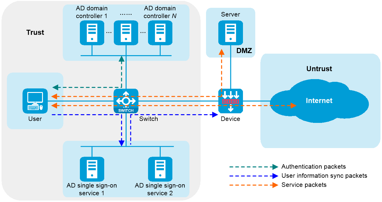
As shown in Figure 1, a user sends the username and password to an Active Directory (AD) domain controller for authentication. After successful authentication, the user synchronizes the identity information (such as the username and IP address) to an AD single sign-on service, which then synchronizes the user's identity information to the device. Once the device obtains the mapping between the username and IP address, the user can directly access network resources after passing authentication by the AD domain controller without authentication by the device. This authentication method is called AD single sign-on.
Figure 1 AD single sign-on diagram
Functions of AD single sign-on service software
The AD single sign-on service software has the following functions:
· Login information collection—Collects a user's login information after successful login of the user and synchronizes the information to the device. The device then sets the user as an online identity user.
· Logout information collection—Collects the user's logout information when the user logs out and synchronizes the information to the device. The device then removes this user from the online identity user list.
· Bulk synchronization of online users—Synchronizes online user information to the device in bulk when receiving a device request for obtaining online users in bulk.
· Simultaneous synchronization of online users to multiple devices—Synchronizes online users to multiple devices simultaneously.
· User information security check—When an AD single sign-on service receives user information, it will perform security checks to prevent nonexistent users from coming online.
For more information about online identity users, see user identification configuration in Security Configuration Guide of the device.
Operating mechanism of AD single sign-on services
To ensure AD single sign-on services operate correctly, perform the following tasks:
1. Install, configure, and start the AD single sign-on services (up to 2) on the AD server.
2. Configure the logon and logout scripts on the AD domain controllers (up to 16).
3. Configure relevant parameters on the device to receive user identity information sent by the AD single sign-on services.
When the device initially joins the AD single sign-on service network, it actively synchronizes full user information and online user information from both the AD domain controllers and the AD single sign-on services. This ensures the continuity of online user services. As shown in Figure 2, the specific process is as follows:
Figure 2 Operating mechanism of AD single sign-on services
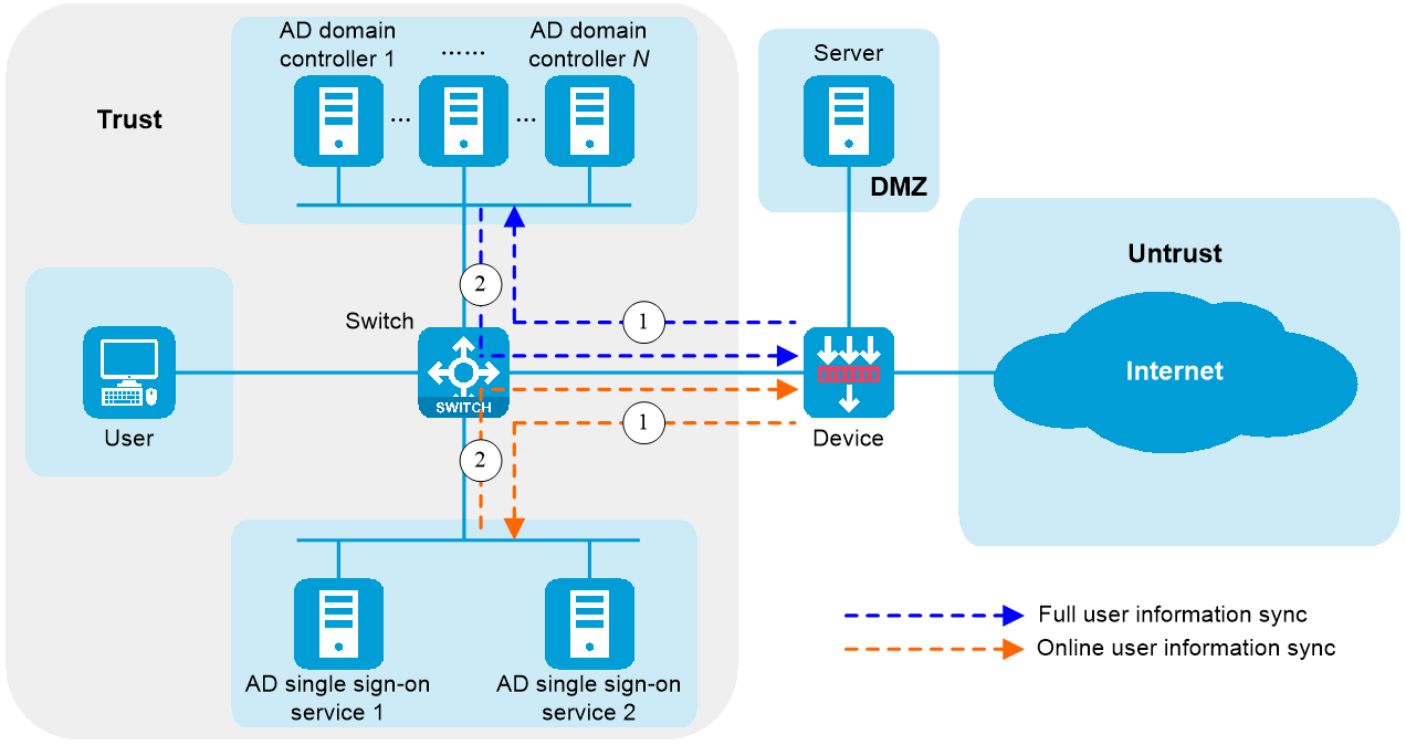
1. The device requests full user information and online user information from an AD domain controller and an AD single sign-on service.
2. The AD domain controller and the AD single sign-on service deploy the full user information and online user information to the device, respectively.
3. Based on the full user information and online user information, the device identifies the corresponding users as all identity users and online identity users, respectively.
The AD single sign-on service operates similarly during user login and logout processes. The following example illustrates the operating mechanism during the login process.
Figure 3 Operating mechanism of AD single sign-on services

1. The user sends the username and password to an AD domain controller for authentication.
2. After successful authentication by the AD server, the AD domain controller deploys the logon script (ReportLogin script) to the user host.
3. The user host executes the logon script and sends the user's identity information to an AD single sign-on service.
4. The AD single sign-on service synchronizes the user's identity information to the device.
5. The device obtains the user's username and IP address from the identity information and adds the mapping between the username and IP address to the online identity user list.
Prerequisites
Software environment requirements
Before installing the AD single sign-on software, check whether any history version of the software has been installed. If so, uninstall the history version and then install the latest version. Make sure that the language of the software is consistent with that of the operating system. Specific interfaces depend on the actual display. The software environment requirements for the AD single sign-on software are as follows. As a best practice, install the latest patches for the corresponding software.
Table 1 Server software configuration requirements
|
Type |
Software |
|
Operating system |
Windows Server 2008 |
|
Windows Server 2012 |
|
|
Windows Server 2016 |
|
|
Windows 7 |
|
|
Windows 10 |
|
|
AD single sign-on |
V002R002 |
Adding firewall rules on the AD server
To ensure the AD single sign-on service communicates normally with both the ReportLogin script and the device, you must add corresponding rules and enable access to the specified service ports on the Windows Firewall with Advanced Security page of the AD server.
For specific service port numbers, see the actually specified ports in the AD single sign-on service configuration files. This example uses port 8826 (in the inbound rule) and port 80 (in the outbound rule).
Adding an inbound rule to enable access to port 8826
To enable normal communication between an AD single sign-on service and the ReportLogin script, add an inbound rule on the Windows Firewall with Advanced Security page and enable access to port 8826. The specific configuration steps are as follows:
1. Select Start > Administrative Tools > Windows Firewall with Advanced Security.
Figure 4 Windows Firewall with Advanced Security page
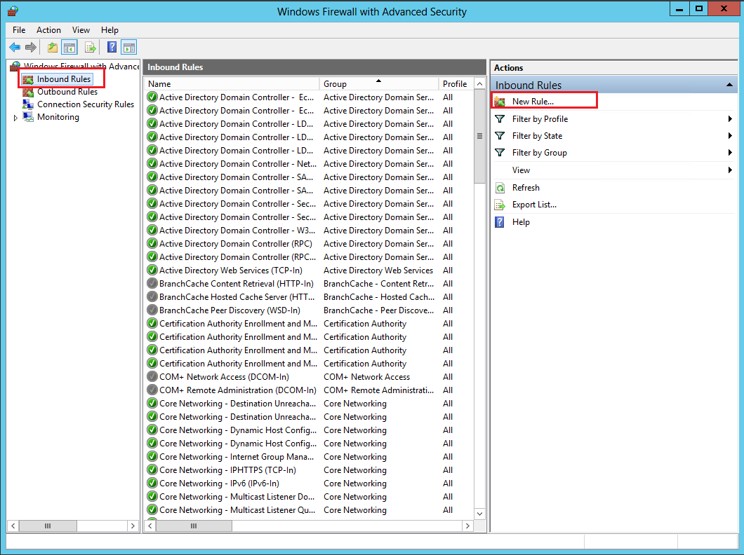
2. On the Windows Firewall with Advanced Security page, select Inbound Rules > New Rule.
Figure 5 New Inbound Rule Wizard page (1)
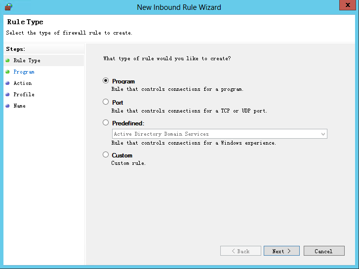
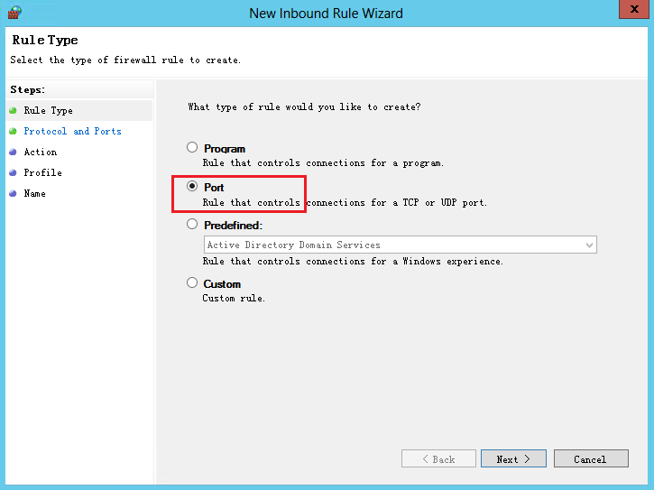
3. On the Rule Type tab, select Port, and then click Next.
Figure 6 New Inbound Rule Wizard page (2)
4. On the Protocol and Ports tab, select TCP, enter 8826 in the Specific local ports field, and then click Next.
Figure 7 New Inbound Rule Wizard page (3)

5. On the Action tab, select Allow the connection, and then click Next.
Figure 8 New Inbound Rule Wizard page (4)

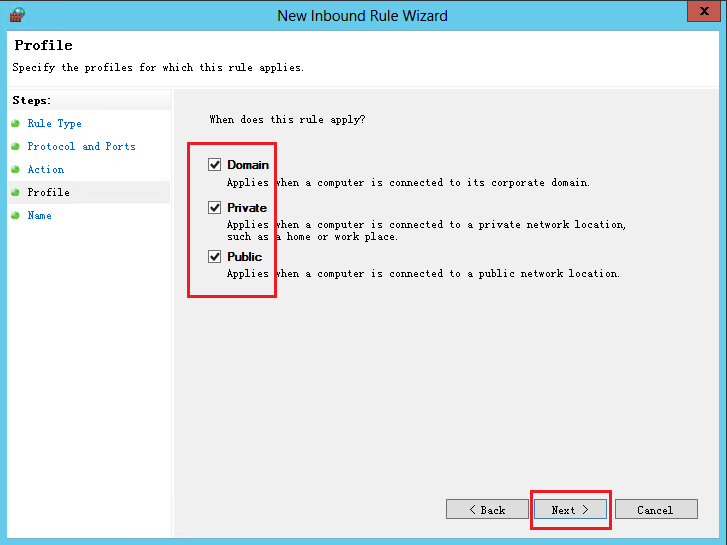
6. On the Profile tab, select all options, and then click Next.
Figure 9 New Inbound Rule Wizard page (5)
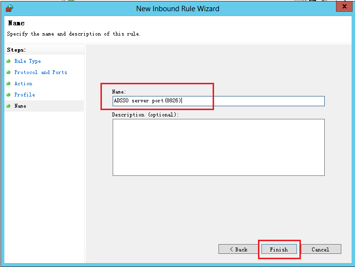
7. On the Name tab, enter the name and description for the rule, and then click Finish.
Figure 10 New Inbound Rule Wizard page (6)
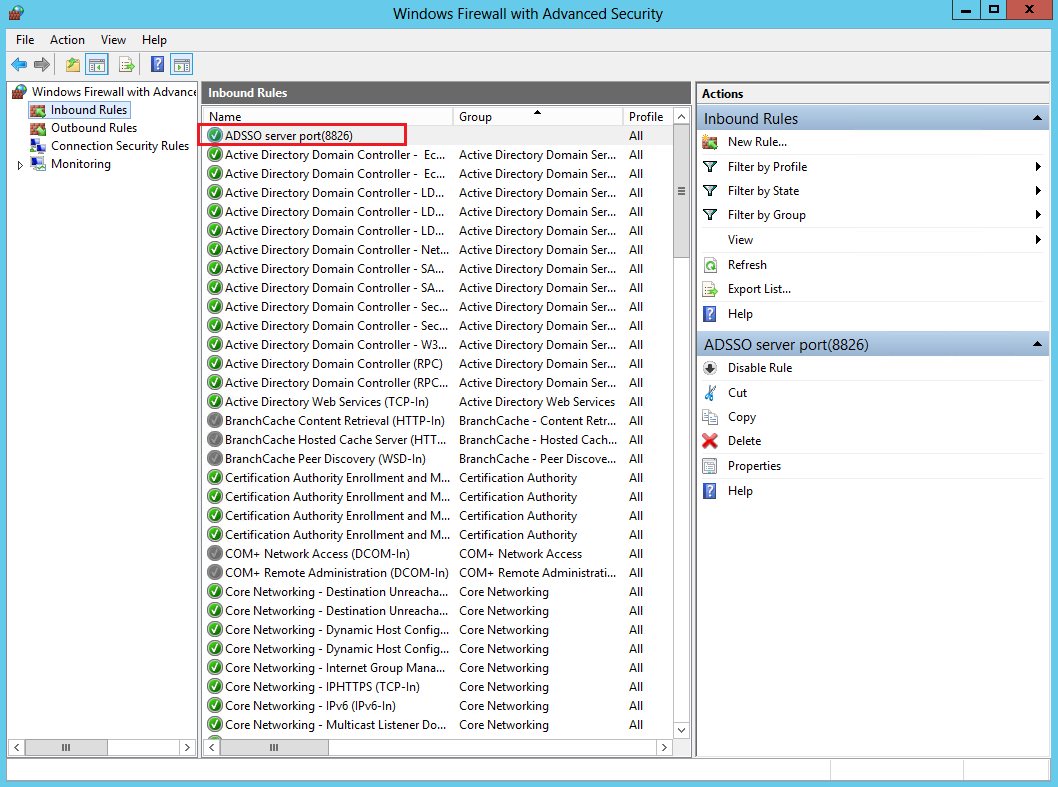
8. View the added inbound rule.
Figure 11 Windows Firewall with Advanced Security page
Adding an outbound rule to enable access to port 80
To ensure normal communication between the AD single sign-on service and the device, add an outbound rule on the Windows Firewall with Advanced Security page and enable access to port 80. The configuration method for an outbound rule is similar to that for an inbound rule. For more information about the specific configuration steps, see "Adding an inbound rule to enable access to port 8826."
Supported endpoint systems
The endpoint operating systems supported by H3C AD single sign-on service include Windows XP, Windows 7, and Windows 10.
AD single sign-on service deployment guide
Installing the AD single sign-on service software
1. Open the executable program setup.exe of the H3C AD single sign-on service software with administrator privileges. The Preparing for Installation page opens. After installation preparation is completed, the License Agreement page opens.
Figure 12 AD single sign-on service installation preparation page

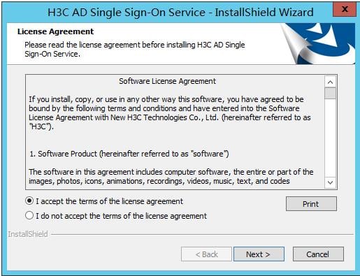
2. Select I accept the terms of the license agreement, and then click Next.
Figure 13 Software license agreement selection page
3. On the Installation Wizard page, click Next.
Figure 14 Installation wizard page

4. On the Select Installation Location page, select the path (this example uses the default path) to install the software, and then click Next.
Figure 15 Installation location selection page

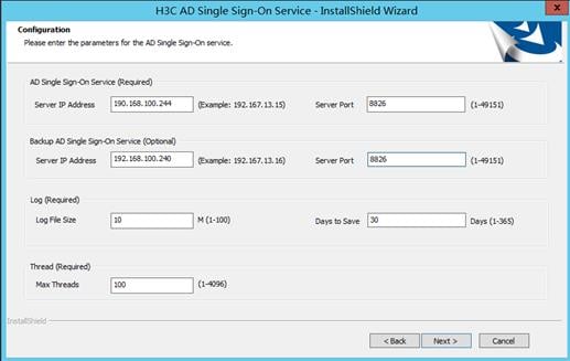
5. On the Configuration page, configure the AD single sign-on service parameters, and then click Next.
Table 2 Service parameters
|
Parameter |
Description |
|
|
AD Single Sign-On Service |
Server IP Address |
IP address of the AD single sign-on server used for communication with the ReportLogin script and the device. This example uses 192.168.100.244. |
|
Server Port |
Port number for the AD single sign-on service. This example uses 8826. |
|
|
Backup AD Single Sign-On Service |
Server IP Address |
IP address of the backup AD single sign-on server used for communication with the ReportLogin script and the device. This example uses 192.168.100.240. |
|
Server Port |
Port number for the backup AD single sign-on service. This example uses 8826. |
|
|
Log |
Log File Size |
Maximum size of a single log file. If the maximum size of a log file is reached, a new log file will be created to continue saving logs. This example uses 10 M. |
|
Days to Save |
Maximum number of days that logs can be saved. This example uses 30 days. |
|
|
Thread |
Max Threads |
Maximum number of threads the AD single sign-on service can open for forwarding user information to the device. This example uses 30. |
Figure 16 Configuration page
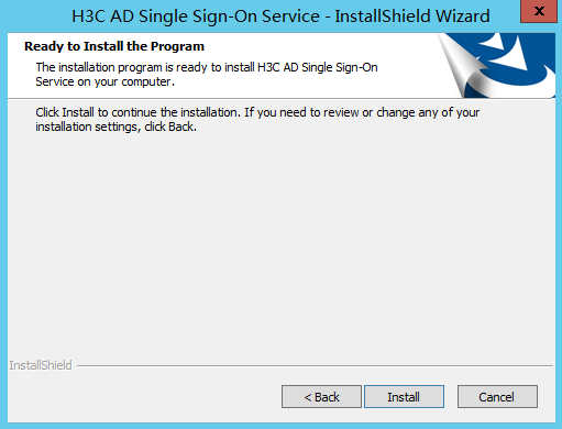
6. On the Ready to Install the Program page, click Install to install the AD single sign-on service software.
Figure 17 Ready to install page
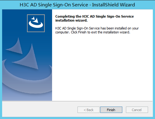
7. On the Installation Wizard page, click Finish to complete the software installation.
Figure 18 Installation wizard page
Configuring the startup type as Automatic (Delayed Start) for the AD single sign-on service
1. Select Start > Administrative Tools > Services.
Figure 19 Service page (1)
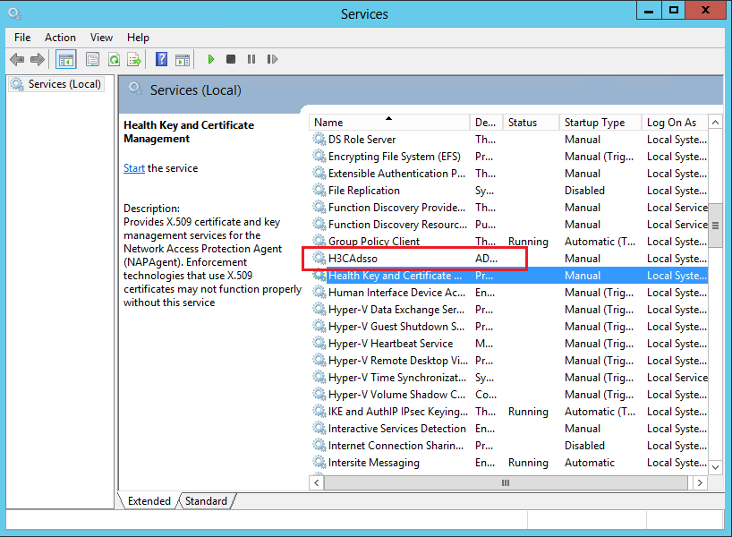
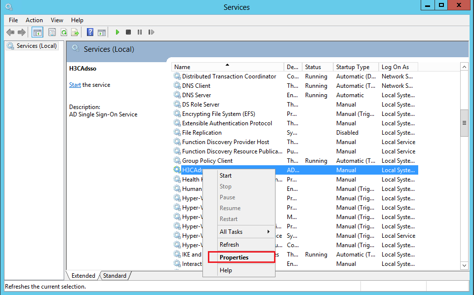
2. On the Services page, select the H3CAdsso service, right-click it, and then select Properties.
Figure 20 Service page (2)
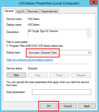
3. On the H3CAdsso Properties (Local Computer) page that opens, set the startup type to Automatic (Delayed Start), and then click OK.
Because the H3CAdsso service requires the Active Directory Domain Services service to start first, you need to set the startup type for the H3CAdsso service to Automatic (Delayed Start).
Figure 21 H3CAdsso Properties (Local Computer) page
Configuring the AD single sign-on service
1. Open the H3C AD Single Sign-On Service management page.
After installing the software, open the management page through the H3C AD Single Sign-On Service shortcut on the desktop.
Figure 22 Shortcut for AD single sign-on service

2. Change the log save path.
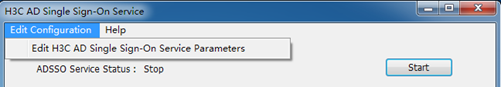
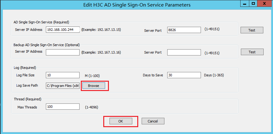
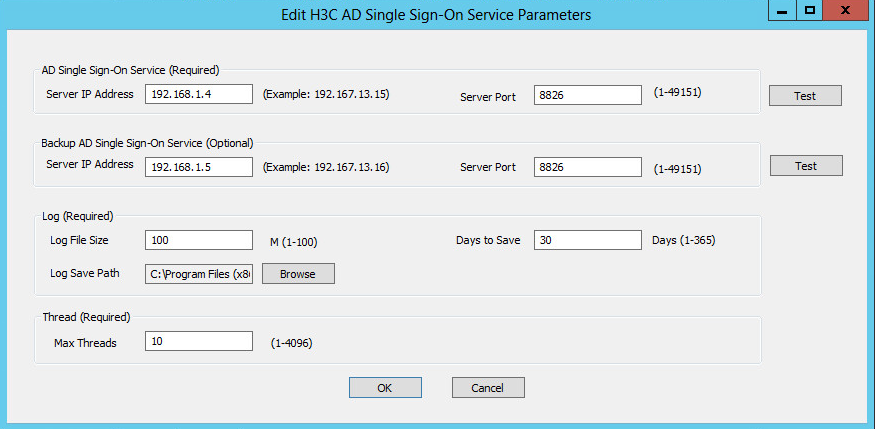
a. On the H3C AD Single Sign-On Service management page, click Edit Configuration, and then click Edit H3C AD Single Sign-On Service Parameters.
Figure 23 Help tab
b. Click Browse to select the log save path (this example uses D:\ADlog), and then click OK.
After the software is installed, the default log save path is the software installation path. Because logs might take a lot of disk space, change the log save path to a non-system installation path after the installation as a best practice.
Figure 24 AD single sign-on service parameter editing page
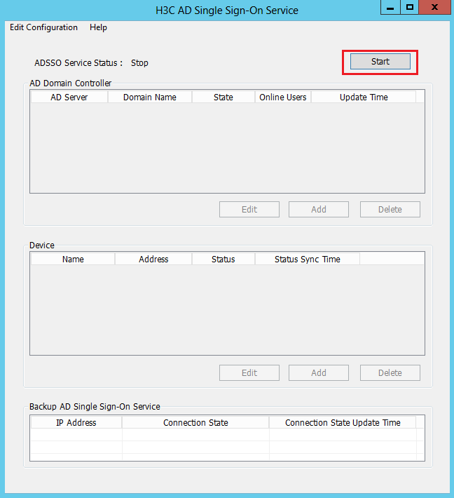
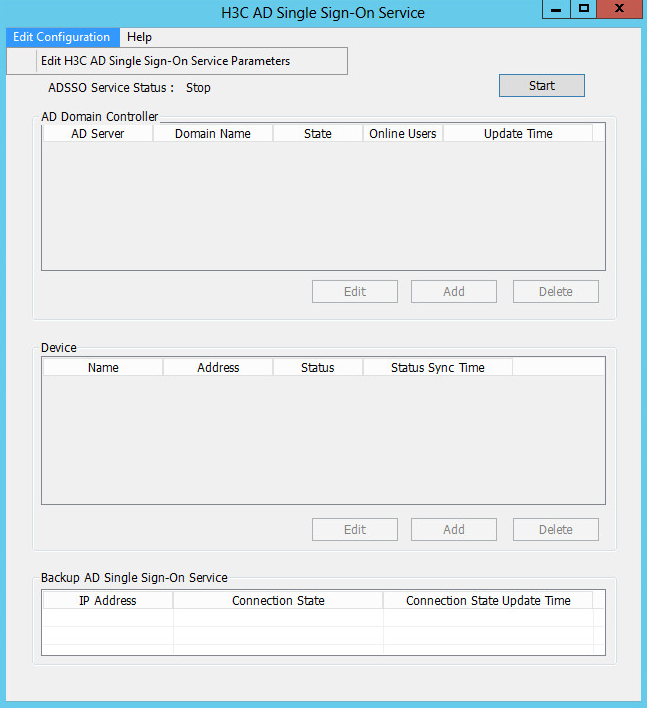
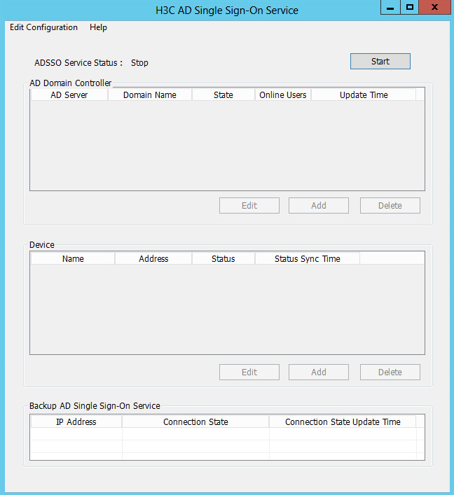
3. Start the service.
Click Start on the H3C AD Single Sign-On Service management page.
Figure 25 AD single sign-on service management page
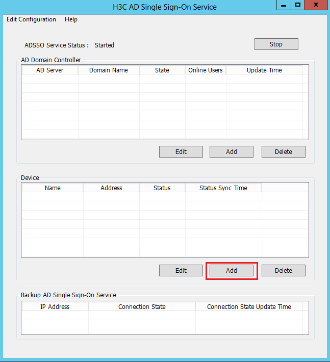
4. Add a device.
After starting the AD single sign-on service, click Add in the Device area to add a device.
Adding a device allows synchronization of online user information from the AD single sign-on service to the added device.
Figure 26 Adding a device
5. Configure device information.
On the Add Device page, configure the parameters, and then click OK.
Table 3 Device parameters
|
Parameter |
Description |
|
Name |
Name of the device. This example uses FW-1. |
|
IP Address |
IP address of the device. This example uses 190.166.148.16. |
|
Port |
Port number for the HTTP service on the device. This example uses 80. |
|
UserName |
RESTful login username on the device. This example uses admin. |
|
Password |
RESTful login password on the device. This example uses admin. |
Figure 27 Device adding page

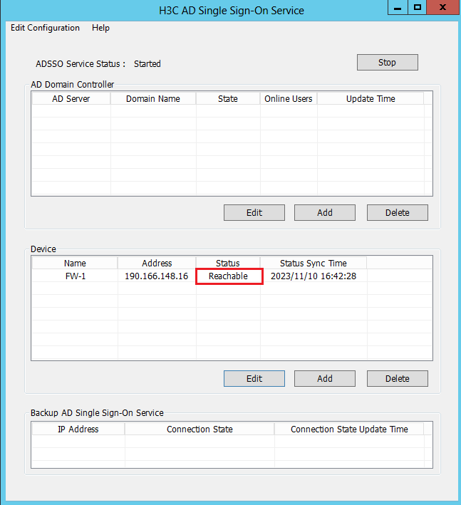
6. After the device is added, you can view that the device is in Reachable status on the H3C AD Single Sign-On Service management page.
The Reachable status is displayed only when the device and the AD single sign-on service are reachable to each other, and you have configured HTTP-based RESTful features on the device.
Because querying and updating the device status take some time, it's normal that the device's status might be temporarily unstable when the service has just started or the device was newly added.
Figure 28 Device status
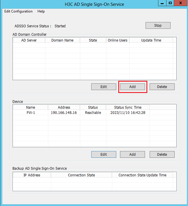
7. Add an AD domain controller.
After starting the AD single sign-on service, click Add in the AD Domain Controller area on the H3C AD Single Sign-On Service management page.
Adding an AD domain controller helps the AD server to implement onboarding of users from multiple domains.
Figure 29 Adding an AD domain controller
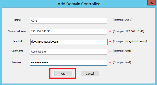
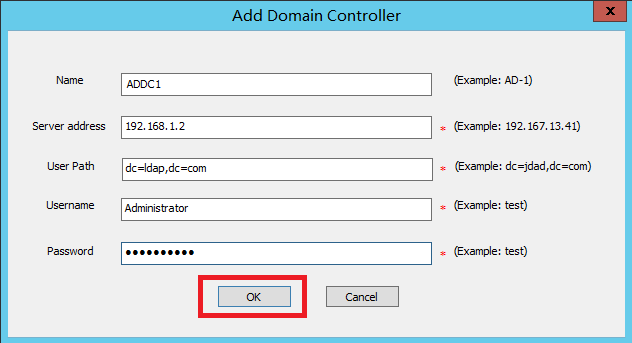
8. Configure the AD domain controller information
On the Add Domain Controller page, configure the parameters, and then click OK.
Table 4 Domain controller parameters
|
Parameter |
Description |
|
Name |
Name of the AD domain controller. This example uses AD-1. |
|
Server Address |
IP address of the AD domain controller. This example uses 190.166.13.148. |
|
User Path |
User path of the AD domain controller. This example uses dc=14890test,dc=com. |
|
Username |
Username for logging in to the AD domain controller. This example uses Administrator. |
|
Password |
Password for logging in to the AD domain controller. This example uses admin. |
Figure 30 AD domain controller adding page
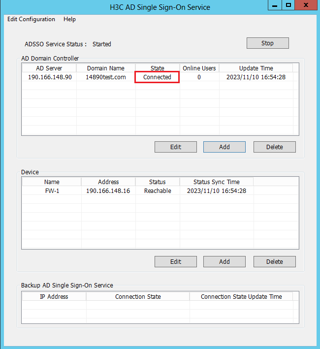
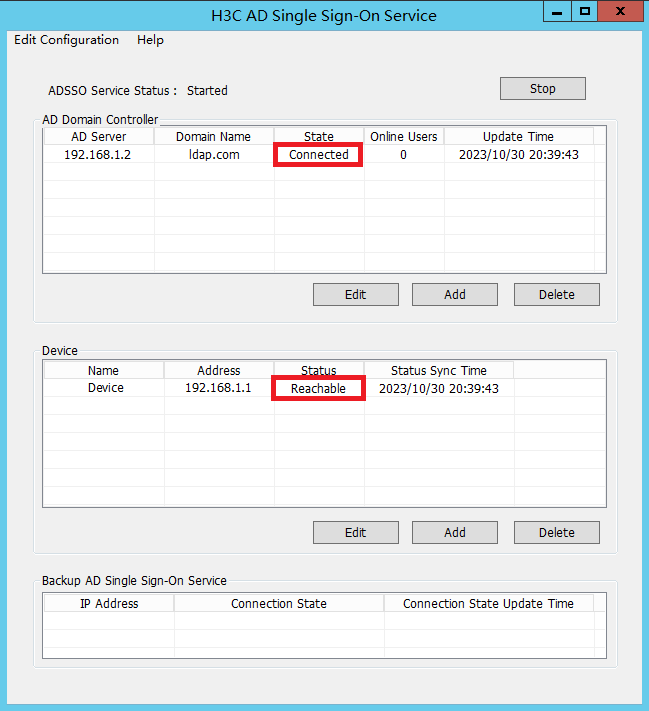
9. After adding the AD domain controller, you can view that the AD domain controller server is in Connected state on the H3C AD Single Sign-On Service management page.
After adding the AD domain controller, make sure that the AD domain controller and the AD single sign-on service are reachable to each other.
Because querying and updating the status of the AD domain controller take some time, it's normal that the controller server's status might be temporarily unstable when the service has just started or the controller was newly added.
Figure 31 AD domain controller status
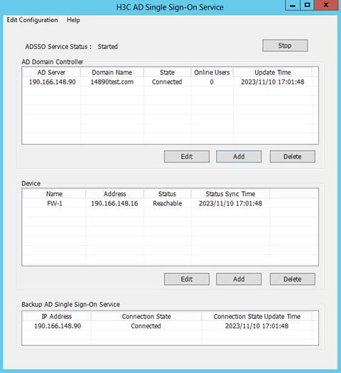
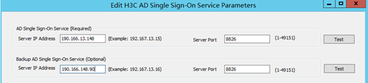
10. If you need two AD single sign-on services to back up each other, configure the server IP address and service port for the backup AD single sign-on service on the Edit AD Single Sign-On Service Parameters page. After successful connection, the statuses are displayed as follows:
Figure 32 AD single sign-on service statuses
AD single sign-on script deployment guide
Configuring the logon script for AD single sign-on
After a user logs in successfully, the logon script is deployed to the user's host to collect and send user identity information. The specific configuration steps for the logon script are as follows:
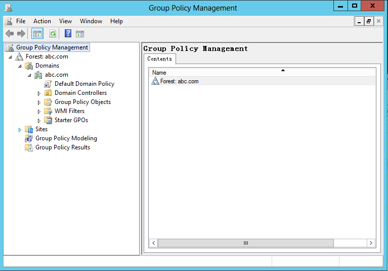
1. Select Start > Administrative Tools > Group Policy Management.
Figure 33 Group policy management page (1)
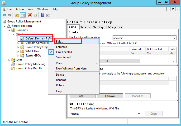
2. On the Group Policy Management page, select the domain to be monitored (abc.com in this example), right-click Default Domain Policy and then select Edit.
Figure 34 Group policy management page (2)
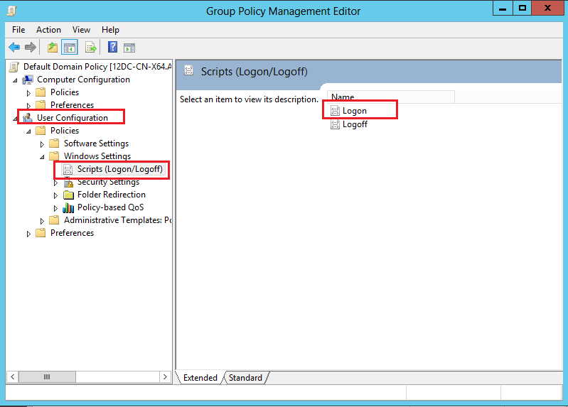
3. On the Group Policy Management Editor page, select User Configuration > Windows Settings > Scripts (Logon/Logout), and then double-click Logon.
Figure 35 Group policy management page (3)
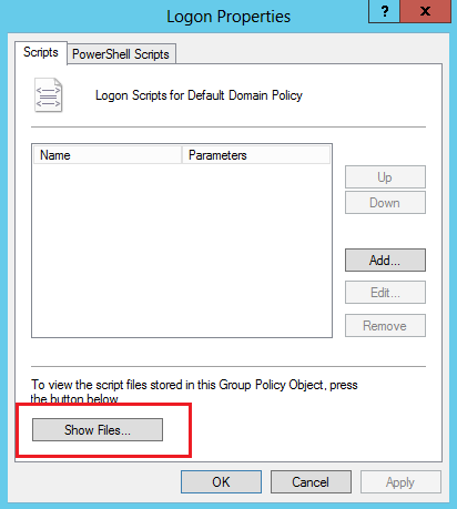
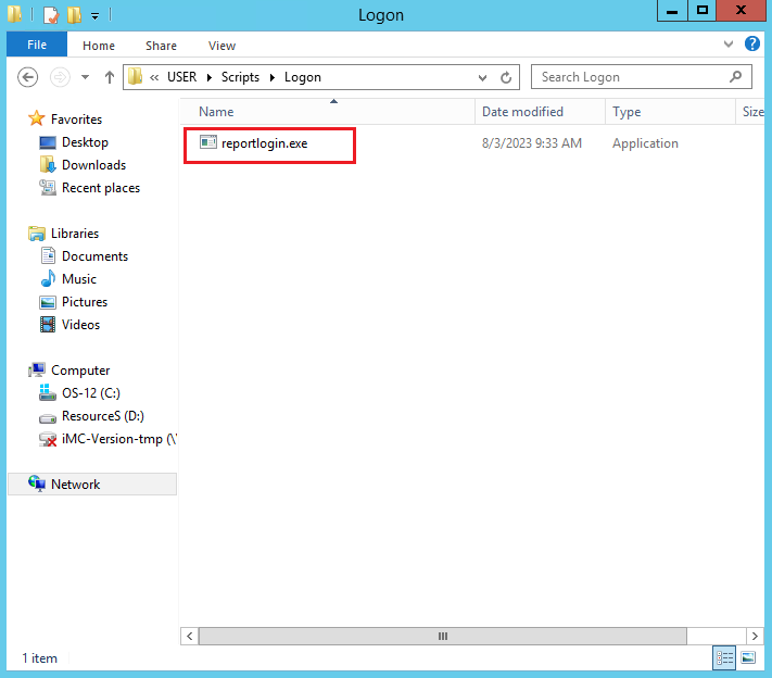
4. On the Logon Properties page, click Show Files to enter the Logon folder.
Figure 36 Logon properties page (1)
5. Copy the reportlogin.exe software from the installation path of the AD single sign-on service to the Logon folder.
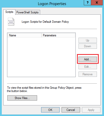
6. On the Logon Properties page, click Add.
Figure 38 Logon properties page (2)
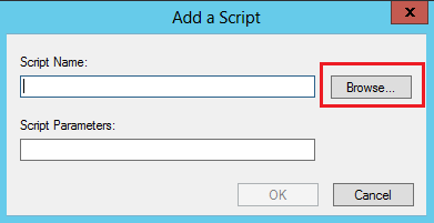
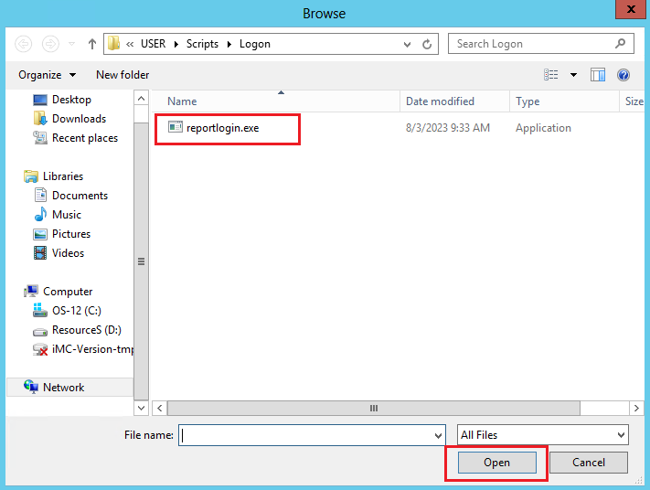
7. On the Add Script page, click Browse, select the reportlogin.exe software from the popup folder, and then click Open.
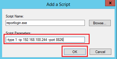
8. On the Add a Script page, configure the required script parameters (IP address 192.168.100.244 and port 8826 in this example), and then click OK.
For the formats and descriptions for the script parameters, see "AD single sign-on script configuration parameters."
For the specific script parameter values, see the actually configured values of the AD single sign-on service parameters. In this example, the script type is logon script, the IP address of the AD single sign-on server is 192.168.100.244, and the port of the AD single sign-on service is 8826.
Figure 40 Script adding page
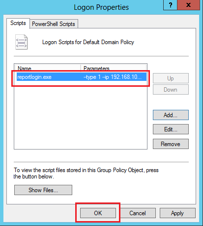
9. On the Logon Properties page, click OK.
Figure 41 Logon properties page (3)
Configuring the logout script for AD single sign-on
When a user logs out, the logout script is deployed to the user's host to collect and send the user's logout identity information. The configuration method of the logout script is similar to that of the logon script. For detailed configuration steps of the logout script, see "Configuring the logon script for AD single sign-on."
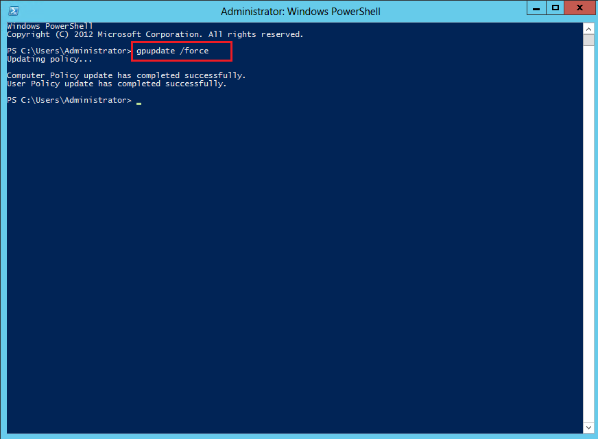
After configuring the logon and logout scripts, you must execute the gpupdate /force command on the AD server console to refresh the policies.
Figure 42 Executing the gpupdate /force command to refresh policies
AD single sign-on script configuration parameters
The configuration parameter formats for the AD single sign-on scripts are as follows:
· --type type-value --ip ip-value --port port-value
· --type type-value --ip ip-value --port port-value --backup-ip ip-value --backup-port port-value
Table 5 Parameters for AD single sign-on scripts
|
Parameter |
Description |
|
--type |
Type of the script. Options include: · 1—Logon. · 2—Logout. |
|
--ip |
IP address of the AD single sign-on server. |
|
--port |
Port for the AD single sign-on service. |
|
--backup-ip |
IP address of the backup AD single sign-on server. |
|
--backup-port |
Port for the backup AD single sign-on service. |
Device configuration guide
Configuring the device to obtain full user information through AD domain controller
To ensure normal communication between the device and the AD domain controller, you must configure the device to synchronize the full identity users from the AD domain controller. The configuration on the device is as follows:
# Enter system view.
<Device> system-view
# Create LDAP server ldap.
[Device] ldap server ldap
# Specify the IP address of the LDAP authentication server as the IP address 192.168.100.244 of the AD domain controller.
[Device-ldap-server-ldap] ip 192.168.100.244
# Specify the administrator DN.
[Device-ldap-server-ldap] login-dn cn=administrator,cn=users,dc=ldap,dc=com
# Set the administrator password to Admin@1234 in plain text.
[Device-ldap-server-ldap] login-password simple Admin@1234
# Configure the base DN for user search.
[Device-ldap-server-ldap] search-base-dn dc=ldap,dc=com
# Include the domain names in the usernames sent to the server.
[Device-ldap-server-ldap] user-parameters user-name-format with-domain
[Device-ldap-server-ldap] quit
# Create LDAP attribute map map1, and map a partial value string of the LDAP attribute named memberof to AAA attribute named user-group.
[Device] ldap attribute-map ldap
[Device-ldap-attr-map-ldap] map ldap-attribute memberof prefix cn= delimiter , aaa-attribute user-group
[Device-ldap-attr-map-ldap] quit
# Create LDAP scheme ldap, specify authentication server ldap, and specify LDAP attribute map map1.
[Device] ldap scheme ldap
[Device-ldap-ldap] authentication-server ldap
[Device-ldap-ldap] attribute-map ldap
[Device-ldap-ldap] quit
# Enable the user identification feature.
[Device] user-identity enable
# Create identity user import policy policy1 and enter its view.
[Device] user-identity user-import-policy policy1
# Set the interval for automatic identity user account import to 1 hour.
[Device-identity-user-impt-policy-policy1] account-update-interval 1
# Specify LDAP scheme ldap for the identity user import policy.
[Device-identity-user-impt-policy-policy1] ldap-scheme ldap
[Device-identity-user-impt-policy-policy1] quit
# Enable automatic identity user account import for identity user import policy policy1.
[Device] user-identity user-account auto-import policy policy1
Configuring the device to obtain online user information through AD single sign-on service
The username and password configured for the AD single sign-on service must be the same as those configured for the RESTful login user on the device. In addition, you must specify the simple keyword to set a password in plaintext form for the RESTful login user on the device. This example uses username admin and password Admin@1234.
To ensure normal communication between the AD single sign-on service and the device, you must configure RESTful access on the device. The configuration on the device is as follows:
# Enable HTTP.
[Device] ip http enable
# Enable RESTful access over HTTP.
[Device] restful http enable
# Create local device management user admin and enter local user view.
[Device] local-user admin class manage
# Set the password for local user admin to Admin@1234 in plain text.
[Device-luser-manage-admin] password simple Admin@1234
# Specify the HTTP service for the local user.
[Device-luser-manage-admin] service-type http
# Specify the user role for the user as network-admin.
[Device-luser-manage-admin] authorization-attribute user-role network-admin
[Device-luser-manage-admin] quit
# Enable the user identification feature.
[Device] user-identity enable
# Create RESTful server adsso and enter its view.
[Device] user-identity restful-server adsso
# Specify http://192.168.100.244:8826/adsso/aduser/onlineUser as the URI used to request online network access user information from the RESTful server.
[Device-restfulserver-adsso] uri get-online-user "http://192.168.100.244:8826/adsso/aduser/onlineUser"
[Device-restfulserver-adsso] quit
# Create identity user import policy policy1.
[Device] user-identity user-import-policy policy1
# Specify RESTful server adsso for the identity user import policy.
[Device-identity-user-impt-policy-policy1] restful-server adsso
[Device-identity-user-impt-policy-policy1] quit
For more information about RESTful login to the device, see login management configuration in Fundamentals Configuration Guide of the device.
Troubleshooting
Abnormal backup AD single sign-on service status
Symptom
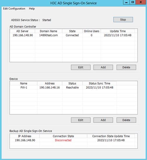
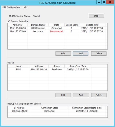
The backup AD server in the backup AD single sign-on service list is in Disconnected state.
Figure 43 Disconnected backup AD single sign-on service
Analysis
The following are the common causes for this issue:
· The primary and backup service configurations of the two single sign-on services are incorrect.
· The corresponding backup AD single sign-on service is running abnormally.
Solution
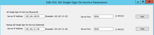
1. Verify that the configurations of the two AD single sign-on services are backups for each other. The heartbeat status can be established normally only when the two services act as backups for each other.
Figure 44 Mutual service backup configuration
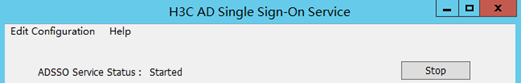
2. Verify that the running statuses of the two AD single sign-on services are Started.
Figure 45 Normal service status
Abnormal device status
Symptom
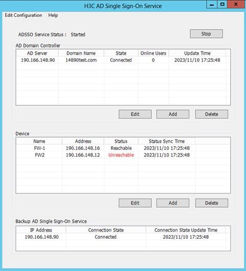
A device in the device list is in Unreachable status.
Figure 46 Abnormal device status
Analysis
The following are the common causes for this type of issue:
· The firewall device itself is abnormal, causing communication failures between the AD single sign-on service and the firewall.
· The username and password configured for the device in the device list are not the same as those configured on the firewall device.
Solution
1. Verify that the firewall is running normally and the communication is normal. Verify that the ping packets between the server and the firewall device can be exchanged.
2. Verify that the username and password configured in the device list are the same as those configured on the firewall device.
Use the username and password configured in the device list to log in to the firewall device. If you cannot log in successfully, edit the username and password for the firewall device in the AD single sign-on service to match those on the firewall.
Abnormal AD domain controller state
Symptom
A domain controller server in the AD domain controller list is in Disconnected state.
Figure 47 Abnormal AD domain controller state
Analysis
The following are the common causes for this type of issue:
· The AD domain controller itself is abnormal, causing communication failures between the AD single sign-on service and the AD domain controller.
· The username and password configured for the controller in the AD domain controller list are not the same as those actually used by the controller.
Solution
1. Verify that the AD domain controller is running normally and the communication is normal. Verify that the ping packets between the server and the AD domain controller can be exchanged.
2. Verify that the username and password configured in the AD domain controller list are the same as those actually used by the controller.
Use the username and password configured in the AD domain controller list to log in to the controller. If you cannot log in successfully, edit the username and password for the controller in the AD domain controller list to match those actually used by the controller.
Example: Configuring user identification with ADSSO authentication
Network configuration
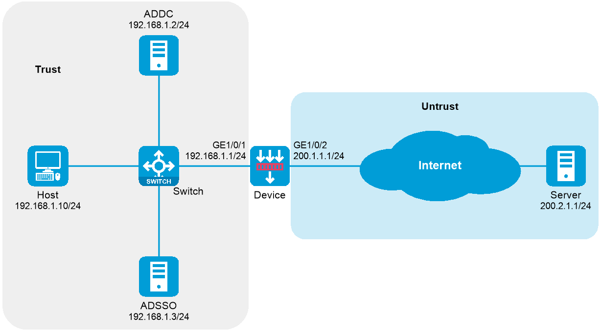
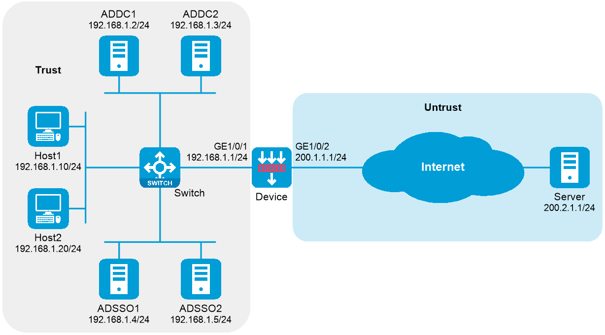
As shown in Figure 48, users transmit their usernames and passwords to the Active Directory domain controller (ADDC) for authentication. Once authenticated, the users synchronize identity information, such as username and IP address, with the Active Directory Single Sign-On service (ADSSO). ADSSO then synchronizes the users’ identity information with the device, allowing the device to obtain username and IP address mapping information.
After passing ADSSO authentication, users can directly access network resources (as the device security policy has provisioned access for them) without needing to authenticate on the device again.
The following information describes the deployment in detail:
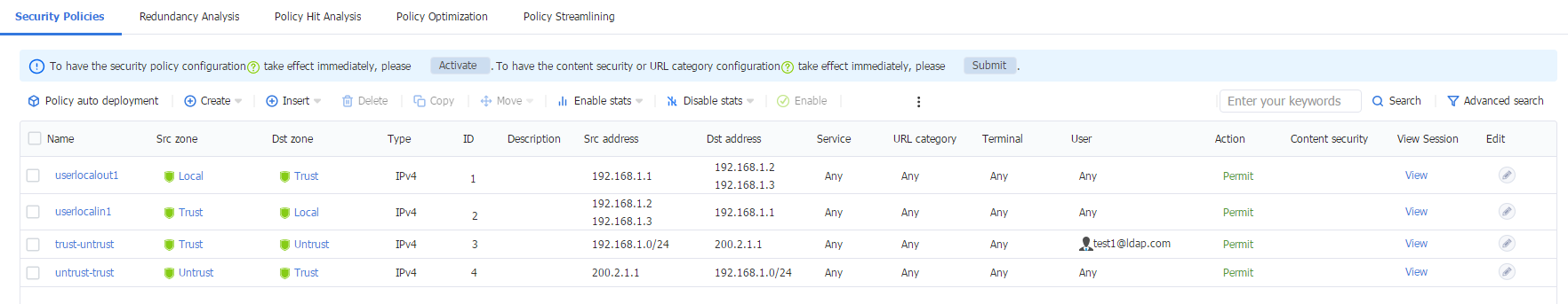
· Configure a security policy rule to permit packets from domain user test1. After logging in via ADSSO, user test1 can access the external network at 200.2.1.1.
· When the security policy rule does not permit packets from domain user test2, user test2 cannot access the external network at 200.2.1.1 after logging in via ADSSO.
· When the security policy rule permit packets from domain user test2, user test2 cannot access the external network at 200.2.1.1 after logging in via ADSSO.
Figure 48 ADSSO network diagram
|
|
NOTE: ADSSO and ADDC can be installed on the same server or on different servers. In this example, ADSSO and ADDC are on different servers. |
Software versions used
This configuration example was created and verified on the following hardware and software:
|
Hardware/software |
Software version used |
|
H3C SecPath F5030-D (Device) |
B64D060SP26 |
|
LDAP server |
Active Directory on Microsoft Windows Server 2012 R2 |
|
ADSSO |
Version V002R002 |
Procedures
The following information is provided based on the assumption that you have basic knowledge of LDAP features and have installed the ADSSO software along with the necessary software, plugins, and scripts.
Configuring users on the LDAP server
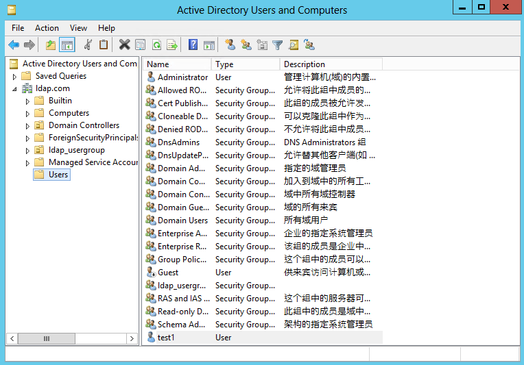
1. Select Start > Management Tools > Active Directory Users and Computers to access the active directory users management interface.
2. In the left navigation tree, click ldap.com, right-click Users and create a new user named test1.
Figure 49 Creating a user

Figure 50 Specifying user information

Figure 51 Setting a password

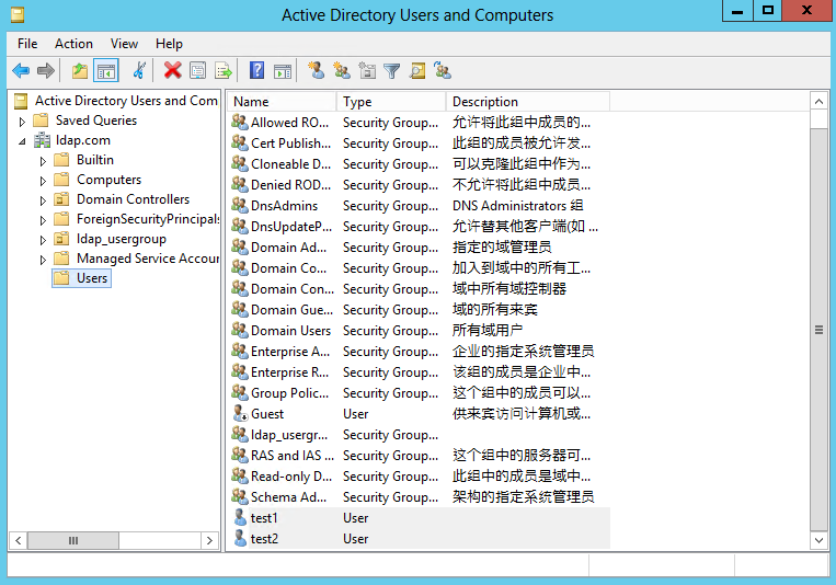
Figure 52 User created
3. Create user test2 in the same way that user test1 is created.
Figure 53 Creating user test2

Configuring ADSSO
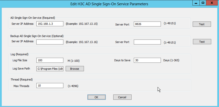
1. Open the H3C AD Single Sign-On Service software. On the top left, click Edit Configuration, and then click Edit H3C AD Single Sign-On Service Parameters.
Figure 54 AD Single Sign-On Service

2. Set up the AD single sign-on service parameters. After completing the configuration, click OK.
Figure 55 Configuring the AD single sign-on service parameters
3. Click Start.
Figure 56 Starting the AD single sign-on service

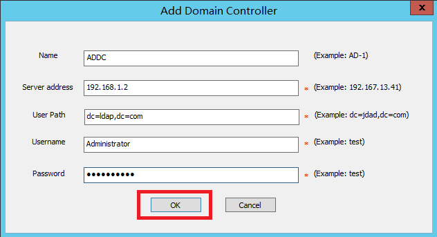
4. Click Add below the AD Domain Controller section to open the Add Domain Controller page. Configure the parameters and then click OK.
|
|
CAUTION: The user Administrator added must be an administrator account created on the AD domain controller. |
Figure 57 Adding a domain controller
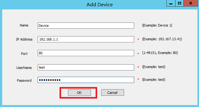
5. Click Add below the Device section to open the Add Device page. Configure the parameters, and then click OK.
|
|
CAUTION: The user test added must be a super administrator already created on the device. |
Figure 58 Adding a device

6. After a device is successfully added, its initial status is unreachable. After the related configurations are complete, the device status will change to reachable.
Figure 59 Viewing the device status
Configuring the device
1. Assign IP addresses to interfaces as planned:
# Assign an IP addresses to interface GigabitEthernet 1/0/1.
<Device> system-view
[Device] interface gigabitethernet 1/0/1
[Device-GigabitEthernet1/0/1] ip address 192.168.1.1 255.255.255.0
[Device-GigabitEthernet1/0/1] quit
# Assign IP addresses to other interfaces in the same way. (Details not shown.)
2. Configure security zones
[Device] security-zone name trust
[Device-security-zone-Trust] import interface gigabitethernet 1/0/1
[Device-security-zone-Trust] quit
[Device] security-zone name untrust
[Device-security-zone-Untrust] import interface gigabitethernet 1/0/2
[Device-security-zone-Untrust] quit
3. Configure a static route:
This example configures a static route. In practice, select the appropriate route configuration method based on the specific circumstances.
# Configure a static route destined for the external network 200.2.1.1/24 with the next hop address being 200.1.1.2.
[Device] ip route-static 200.2.1.1 24 200.1.1.2
4. Configure security policy rules for the Trust and Local security zones to permit communication between the device and the AD servers. Configure security policy rules for the Untrust and Trust security zones to permit communication between the user and the server on the Internet.
# Configure a security policy rule named userlocalout1 to allow the device to send packets to ADDC and ADSSO servers.
[Device] security-policy ip
[Device-security-policy-ip] rule name userlocalout1
[Device-security-policy-ip-1-userlocalout1] source-zone local
[Device-security-policy-ip-1-userlocalout1] destination-zone trust
[Device-security-policy-ip-1-userlocalout1] source-ip-host 192.168.1.1
[Device-security-policy-ip-1-userlocalout1] destination-ip-host 192.168.1.2
[Device-security-policy-ip-1-userlocalout1] destination-ip-host 192.168.1.3
[Device-security-policy-ip-1-userlocalout1] action pass
[Device-security-policy-ip-1-userlocalout1] quit
# Configure a security policy rule named userlocalin1 to allow the ADDC and ADSSO servers to send packets to the device.
[Device-security-policy-ip] rule name userlocalin1
[Device-security-policy-ip-2-userlocalin1] source-zone trust
[Device-security-policy-ip-2-userlocalin1] destination-zone local
[Device-security-policy-ip-2-userlocalin1] source-ip-host 192.168.1.2
[Device-security-policy-ip-2-userlocalin1] source-ip-host 192.168.1.3
[Device-security-policy-ip-2-userlocalin1] destination-ip-host 192.168.1.1
[Device-security-policy-ip-2-userlocalin1] action pass
[Device-security-policy-ip-2-userlocalin1] quit
# Create a security policy rule named trust-untrust to allow user test1 to access the server on the Internet.
[Device-security-policy-ip] rule name trust-untrust
[Device-security-policy-ip-3-untrust-trust] source-zone trust
[Device-security-policy-ip-3-untrust-trust] destination-zone untrust
[Device-security-policy-ip-3-untrust-trust] source-ip-subnet 192.168.1.1 24
[Device-security-policy-ip-3-untrust-trust] destination-ip-host 200.2.1.1
[Device-security-policy-ip-3-untrust-trust] user test1 domain ldap.com
[Device-security-policy-ip-3-untrust-trust] action pass
[Device-security-policy-ip-3-untrust-trust] quit
# Configure a security policy rule named untrust-trust to allow the server to send packets to the user.
[Device-security-policy-ip] rule name untrust-trust
[Device-security-policy-ip-4-trust-untrust] source-zone untrust
[Device-security-policy-ip-4-trust-untrust] destination-zone trust
[Device-security-policy-ip-4-trust-untrust] source-ip-host 200.2.1.1
[Device-security-policy-ip-4-trust-untrust] destination-ip-subnet 192.168.1.1 24
[Device-security-policy-ip-4-trust-untrust] action pass
[Device-security-policy-ip-4-trust-untrust] quit
[Device-security-policy-ip] quit
5. Configure the device to obtain full user information through ADDC:
# Create LDAP server ldap.
[Device] ldap server ldap
# Specify the IP address of the LDAP authentication server as the IP address 192.168.100.244 of the AD domain controller.
[Device-ldap-server-ldap] ip 192.168.1.2
# Specify the administrator DN.
[Device-ldap-server-ldap] login-dn cn=administrator,cn=users,dc=ldap,dc=com
# Set the administrator password to Admin@1234 in plain text.
[Device-ldap-server-ldap] login-password simple Admin@1234
# Configure the base DN for user search.
[Device-ldap-server-ldap] search-base-dn dc=ldap,dc=com
# Include the domain names in the usernames sent to the LDAP server.
[Device-ldap-server-ldap] user-parameters user-name-format with-domain
[Device-ldap-server-ldap] quit
# Create LDAP attribute map map1, and map a partial value string of the LDAP attribute named memberof to AAA attribute named user-group.
[Device] ldap attribute-map ldap
[Device-ldap-attr-map-ldap] map ldap-attribute memberof prefix cn= delimiter , aaa-attribute user-group
[Device-ldap-attr-map-ldap] quit
# Create LDAP scheme ldap, specify authentication server ldap, and specify LDAP attribute map map1.
[Device] ldap scheme ldap
[Device-ldap-ldap] authentication-server ldap
[Device-ldap-ldap] attribute-map ldap
[Device-ldap-ldap] quit
# Enable the user identification feature.
[Device] user-identity enable
# Create identity user import policy policy1 and enter its view.
[Device] user-identity user-import-policy policy1
# Set the interval for automatic identity user account import to 1 hour.
[Device-identity-user-impt-policy-policy1] account-update-interval 1
# Specify LDAP scheme ldap for the identity user import policy.
[Device-identity-user-impt-policy-policy1] ldap-scheme ldap
[Device-identity-user-impt-policy-policy1] quit
# Enable automatic identity user account import for identity user import policy policy1.
[Device] user-identity user-account auto-import policy policy1
6. Configure the device to obtain online user information through ADSSO:
# Enable HTTP.
[Device] ip http enable
# Enable RESTful access over HTTP.
[Device] restful http enable
# Create local device management user test for RESTful login and enter local user view.
[Device] local-user test class manage
# Set the password for local user test to Admin@1234 in plain text.
[Device-luser-manage-test] password simple Admin@1234
# Specify the HTTP service for the local user.
[Device-luser-manage-test] service-type http
# Specify the user role for the user as network-admin.
[Device-luser-manage-test] authorization-attribute user-role network-admin
[Device-luser-manage-test] quit
# Enable the user identification feature.
[Device] user-identity enable
# Create RESTful server adsso and enter its view.
[Device] user-identity restful-server adsso
# Specify the URI used to request online network access user information from the RESTful server as http://192.168.1.3:8826/adsso/aduser/onlineUser.
[Device-restfulserver-adsso] uri get-online-user "http://192.168.1.3:8826/adsso/aduser/onlineUser"
[Device-restfulserver-adsso] quit
# Create identity user import policy policy1.
[Device] user-identity user-import-policy policy1
# Specify RESTful server adsso for the identity user import policy.
[Device-identity-user-impt-policy-policy1] restful-server adsso
[Device-identity-user-impt-policy-policy1] quit
Verifying the configuration
Verifying login of user test1
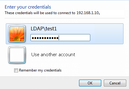
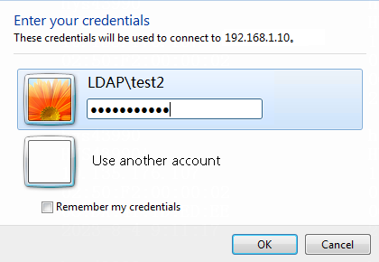
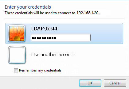
1. Log in to the host that has joined the domain ldap.com by using the domain user test1.
Figure 60 Entering user credentials
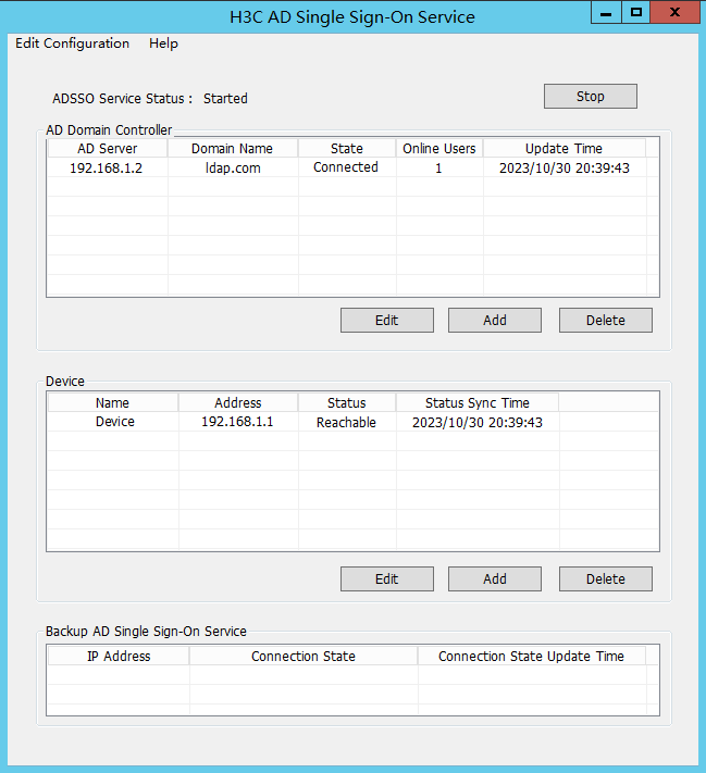
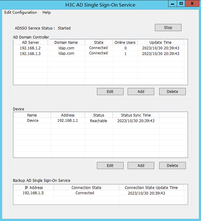
2. After domain user test1 successfully logs in, view the number of online users on ADSSO.
Figure 61 AD Single Sign-On Service

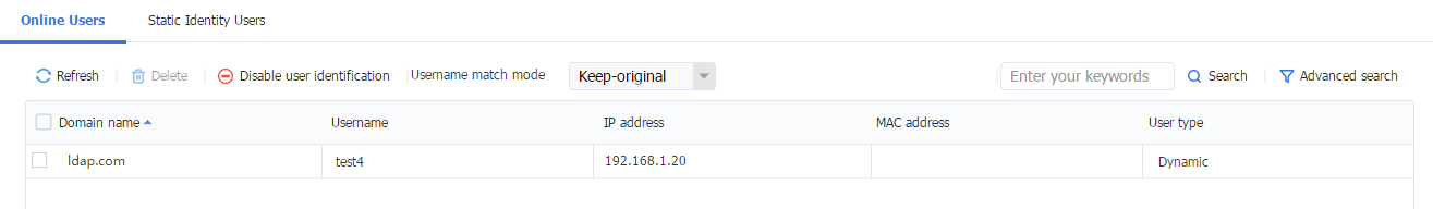
3. Log in to the Web interface of the device, navigate to the Objects > User > User Management > Online Users page. View online users on the page.
Figure 62 Online Users

4. On the host, ping external address 200.2.1.1. The address can be pinged successfully, indicating that user test1 can access the external network at 200.2.1.1.
C:\Users\test1>ping 200.2.1.1 –t
Pinging 200.2.1.1 with 32 bytes of data:
Reply from 200.2.1.1: bytes=32 time<1ms TTL=254
Reply from 200.2.1.1: bytes=32 time<1ms TTL=254
Reply from 200.2.1.1: bytes=32 time<1ms TTL=254
Reply from 200.2.1.1: bytes=32 time<1ms TTL=254
Reply from 200.2.1.1: bytes=32 time<1ms TTL=254
Reply from 200.2.1.1: bytes=32 time<1ms TTL=254
Reply from 200.2.1.1: bytes=32 time<1ms TTL=254
Verifying login of user test2
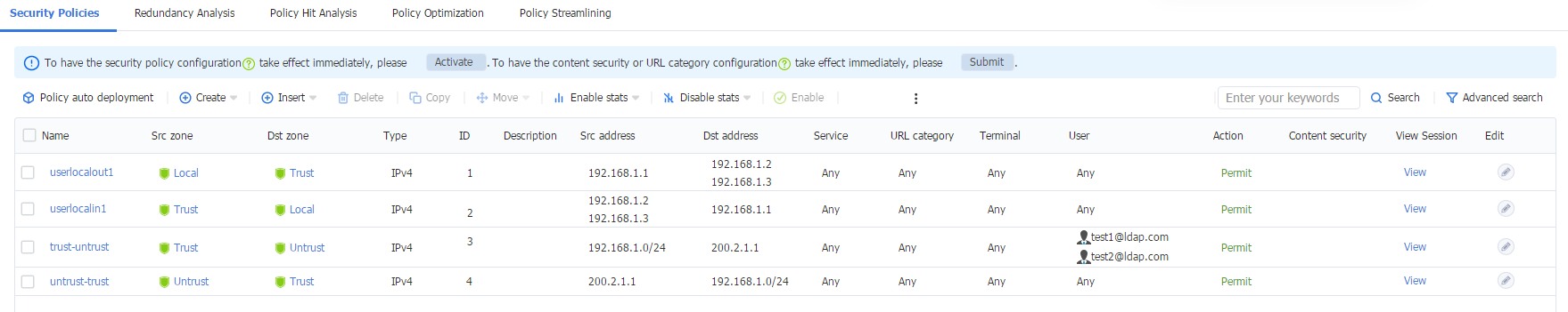
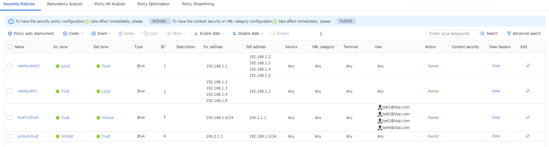
1. Log in to the Web interface of the device, and then navigate to the Policies > Security Policies > Security Policies page. Verify that the security policy only allows traffic from LDAP domain user test1.
Figure 63 Security policies
2. Log in to the host that has joined the domain ldap.com by using the domain user test2.
Figure 64 Logging in using domain account
3. After domain user test2 successfully logs in, view the number of online users on ADSSO.
Figure 65 AD Single Sign-On Service
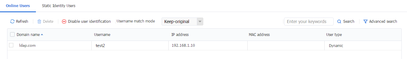
4. Log in to the Web interface of the device, navigate to the Objects > User > User Management > Online Users page. View online users on the page.
Figure 66 Online Users

5. Ping external address 200.2.1.1 from the host. The ping fails, indicating that user test2 cannot access the Internet.
C:\Users\test2>ping 200.2.1.1 –t
Pinging 200.2.1.1 with 32 bytes of data:
Request timed out
Request timed out
Request timed out
Request timed out
Request timed out
Request timed out
Request timed out
Verifying login of user test2 after the security policy permits packets of test2
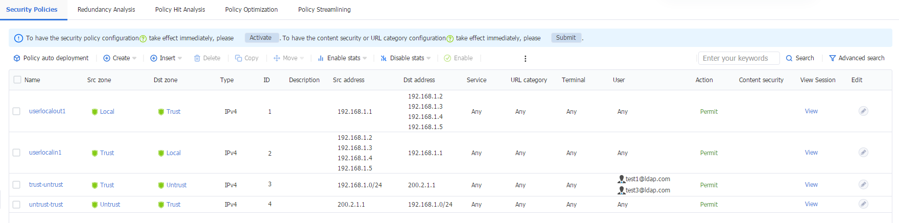
1. Log in to the Web interface of the device, and then navigate to the Policies > Security Policies > Security Policies page. The policy only permit packets from user test1, so packets from user test2 will be discarded and cannot access the external network.
Figure 67 Security policies

2. To allow domain user test2 to access the external network at 200.2.1.1, add user test2 to the security policy as shown in the figure below.
Figure 68 Security policies
3. Ping the external address 200.2.1.1 again from the host. The ping succeeds, indicating that user test2 can also access the Internet.
C:\Users\test2>ping 200.2.1.1 –t
Pinging 200.2.1.1 with 32 bytes of data:
Reply from 200.2.1.1: bytes=32 time<1ms TTL=254
Reply from 200.2.1.1: bytes=32 time<1ms TTL=254
Reply from 200.2.1.1: bytes=32 time<1ms TTL=254
Reply from 200.2.1.1: bytes=32 time<1ms TTL=254
Reply from 200.2.1.1: bytes=32 time<1ms TTL=254
Reply from 200.2.1.1: bytes=32 time<1ms TTL=254
Reply from 200.2.1.1: bytes=32 time<1ms TTL=254
Configuration files
#
interface GigabitEthernet1/0/1
ip address 192.168.1.1 255.255.255.0
#
interface GigabitEthernet1/0/2
ip address 200.1.1.1 255.255.255.0
#
security-zone name Trust
import interface GigabitEthernet1/0/1
#
security-zone name Untrust
import interface GigabitEthernet1/0/2
#
ip route-static 200.2.1.0 24 200.1.1.2
#
ldap server ldap
login-dn cn=administrator,cn=users,dc=ldap,dc=com
search-base-dn dc=ldap,dc=com
ip 192.168.1.2
login-password simple Admin@1234
user-parameters user-name-format with-domain
#
ldap scheme ldap
authentication-server ldap
attribute-map ldap
#
ldap attribute-map ldap
map ldap-attribute memberof prefix cn= delimiter , aaa-attribute user-group
#
local-user test class manage
password simple Admin@1234
service-type http
authorization-attribute user-role network-admin
#
restful http enable
#
ip http enable
#
user-identity enable
user-identity user-account auto-import policy policy1
#
user-identity restful-server adsso
uri get-online-user http://192.168.1.3:8826/adsso/aduser/onlineUser
#
user-identity user-import-policy policy1
account-update-interval 1
restful-server adsso
ldap-scheme ldap
#
security-policy ip
rule 1 name userlocalout1
action pass
source-zone local
destination-zone trust
source-ip-host 192.168.1.1
destination-ip-host 192.168.1.2
destination-ip-host 192.168.1.3
rule 2 name userlocalin1
action pass
source-zone trust
destination-zone local
source-ip-host 192.168.1.2
source-ip-host 192.168.1.3
destination-ip-host 192.168.1.1
rule 3 name trust-untrust
action pass
source-zone trust
destination-zone untrust
source-ip-subnet 192.168.1.0 255.255.255.0
destination-ip-host 200.2.1.1
user test1 domain ldap.com
rule 4 name untrust-trust
action pass
source-zone untrust
destination-zone trust
source-ip-host 200.2.1.1
destination-ip-subnet 192.168.1.0 255.255.255.0
Example: Configuring user identification with dual-active ADSSO servers
Network configuration
As shown in Figure 69, users transmit their usernames and passwords to the Active Directory domain controller (ADDC) for authentication. Once authenticated, the users synchronize identity information, such as username and IP address, with the Active Directory Single Sign-On service (ADSSO). ADSSO then synchronizes the users’ identity information with the device, allowing the device to obtain username and IP address mapping information.
After passing ADSSO authentication, users can directly access network resources (as the device security policy has provisioned access for them) without needing to authenticate on the device again.
The following information describes the deployment in detail:
· Configure a security policy rule to permit packets from domain users test1 and test3. After logging in via ADSSO, user test1 can access the external network at 200.2.1.1.
· When the security policy rule does not permit packets from domain users test2 and test4, user test2 cannot access the external network at 200.2.1.1 after logging in via ADSSO.
· When the security policy rule permits packets from domain users test2 and test4, users test2 and test4 can access the external network at 200.2.1.1 after logging in via ADSSO.
· When one of the ADSSO servers fails, users can still log in normally and access the external network at 200.2.1.1.
Figure 69 ADSSO network diagram
|
|
NOTE: ADSSO and ADDC can be installed on the same server or on different servers. In this example, ADSSO and ADDC are on different servers. |
Software versions used
This configuration example was created and verified on the following hardware and software:
|
Hardware/software |
Software version used |
|
H3C SecPath F5030-D (Device) |
B64D060SP26 |
|
LDAP server |
Active Directory on Microsoft Windows Server 2012 R2 |
|
ADSSO software |
Version V002R002 |
Procedures
The following information is provided based on the assumption that you have basic knowledge of LDAP features and have installed the ADSSO software along with the necessary software, plugins, and scripts.
Configuring users on the LDAP server
1. Select Start > Management Tools > Active Directory Users and Computers to access the active directory users management interface.
2. In the left navigation tree, click ldap.com, right-click Users and create a new user named test1.
Figure 70 Creating a user
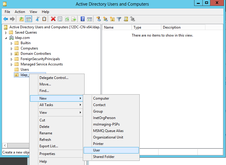
Figure 71 Specifying user information
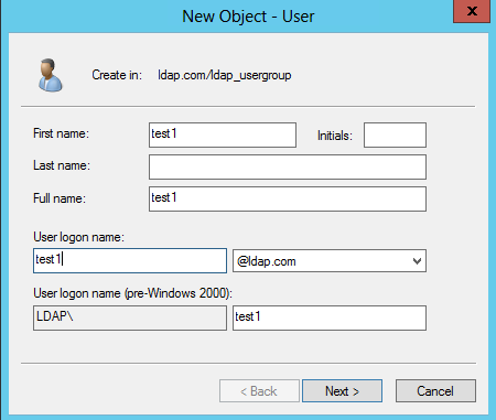
Figure 72 Setting the password
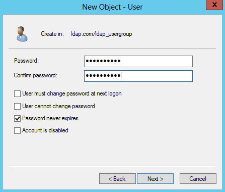
Figure 73 User created

3. Create user test2 in the same way that user test1 is created.
Figure 74 Creating user test2
4. Create users test3 and test4 on ADDC2 in the same way that users test1 and test2 are created.
Configuring ADSSO
1. Open the H3C AD Single Sign-On Service software. On the top left, click Edit Configuration, and then click Edit H3C AD Single Sign-On Service Parameters.
Figure 75 AD Single Sign-On Service
2. Set up the AD single sign-on service parameters. After completing the configuration, click OK.
Figure 76 Configuring the AD single sign-on service parameters
3. Click Start.
Figure 77 Starting the AD single sign-on service
4. Click Add below the AD Domain Controller section to open the Add Domain Controller page. Configure the parameters and then click OK.
|
|
CAUTION: The user Administrator added must be an administrator account created on the AD domain controller. |
Figure 78 Adding a domain controller

5. Click Add below the Device section to open the Add Device page. Configure the parameters, and then click OK.
|
|
CAUTION: The user test added must be a super administrator already created on the device. |
Figure 79 Add devices
6. After a device is successfully added, its initial status is unreachable. After the related configurations are complete, the device status will change to reachable.
Figure 80 Viewing the device status

7. On the other ADSSO, swap the previous AD Single Sign-On Service parameter settings with the Backup-AD Single Sign-On Service parameter settings. All other configurations remaining the same as the previous settings.
Configuring the device
1. Assign IP addresses to interfaces as planned:
# Assign IP address to interface GigabitEthernet 1/0/1.
<Device> system-view
[Device] interface gigabitethernet 1/0/1
[Device-GigabitEthernet1/0/1] ip address 192.168.1.1 255.255.255.0
[Device-GigabitEthernet1/0/1] quit
# Assign IP addresses to other interfaces in the same way. (Details not shown.)
2. Configure security zones
[Device] security-zone name trust
[Device-security-zone-Trust] import interface gigabitethernet 1/0/1
[Device-security-zone-Trust] quit
[Device] security-zone name untrust
[Device-security-zone-Untrust] import interface gigabitethernet 1/0/2
[Device-security-zone-Untrust] quit
3. Configure a static route.
This example configures a static route. In actual network setup, select the appropriate route configuration method based on the specific circumstances.
# Configure a static route destined for the external network 200.2.1.1/24 with the next hop address being 200.1.1.2.
[Device] ip route-static 200.2.1.1 24 200.1.1.2
4. Configure security policy rules for the Trust and Local security zones to permit communication between the device and the AD server. Configure security policy rules for the Untrust and Trust security zones to permit users to access the server on the Internet.
# Configure a security policy rule named userlocalout1 to allow the device to send packets to ADDC and ADSSO.
[Device] security-policy ip
[Device-security-policy-ip] rule name userlocalout1
[Device-security-policy-ip-1-userlocalout1] source-zone local
[Device-security-policy-ip-1-userlocalout1] destination-zone trust
[Device-security-policy-ip-1-userlocalout1] source-ip-host 192.168.1.1
[Device-security-policy-ip-1-userlocalout1] destination-ip-host 192.168.1.2
[Device-security-policy-ip-1-userlocalout1] destination-ip-host 192.168.1.3
[Device-security-policy-ip-1-userlocalout1] destination-ip-host 192.168.1.4
[Device-security-policy-ip-1-userlocalout1] destination-ip-host 192.168.1.5
[Device-security-policy-ip-1-userlocalout1] action pass
[Device-security-policy-ip-1-userlocalout1] quit
# Configure a security policy rule named userlocalin1 to allow the ADDC and ADSSO servers to send packets to the device.
[Device-security-policy-ip] rule name userlocalin1
[Device-security-policy-ip-2-userlocalin1] source-zone trust
[Device-security-policy-ip-2-userlocalin1] destination-zone local
[Device-security-policy-ip-2-userlocalin1] source-ip-host 192.168.1.2
[Device-security-policy-ip-2-userlocalin1] source-ip-host 192.168.1.3
[Device-security-policy-ip-2-userlocalin1] source-ip-host 192.168.1.4
[Device-security-policy-ip-2-userlocalin1] source-ip-host 192.168.1.5
[Device-security-policy-ip-2-userlocalin1] destination-ip-host 192.168.1.1
[Device-security-policy-ip-2-userlocalin1] action pass
[Device-security-policy-ip-2-userlocalin1] quit
# Configure a security policy rule named trust-untrust to allow users test1 and test3 to access to the server on the Internet.
[Device-security-policy-ip] rule name trust-untrust
[Device-security-policy-ip-3-untrust-trust] source-zone trust
[Device-security-policy-ip-3-untrust-trust] destination-zone untrust
[Device-security-policy-ip-3-untrust-trust] source-ip-subnet 192.168.1.1 24
[Device-security-policy-ip-3-untrust-trust] destination-ip-host 200.2.1.1
[Device-security-policy-ip-3-untrust-trust] user test1 domain ldap.com
[Device-security-policy-ip-3-untrust-trust] user test3 domain ldap.com
[Device-security-policy-ip-3-untrust-trust] action pass
[Device-security-policy-ip-3-untrust-trust] quit
# Configure a security policy rule named untrust-trust to allow the server to send packets to the users.
[Device-security-policy-ip] rule name untrust-trust
[Device-security-policy-ip-4-trust-untrust] source-zone untrust
[Device-security-policy-ip-4-trust-untrust] destination-zone trust
[Device-security-policy-ip-4-trust-untrust] source-ip-host 200.2.1.1
[Device-security-policy-ip-4-trust-untrust] destination-ip-subnet 192.168.1.1 24
[Device-security-policy-ip-4-trust-untrust] action pass
[Device-security-policy-ip-4-trust-untrust] quit
[Device-security-policy-ip] quit
5. Configuring the device to obtain full user information through ADDC
# Create an LDAP server named ldap1.
[Device] ldap server ldap1
# Specify the IP address of the LDAP authentication server as the IP address 192.168.100.244 of the AD domain controller.
[Device-ldap-server-ldap1] ip 192.168.1.2
# Specify the administrator DN.
[Device-ldap-server-ldap1] login-dn cn=administrator,cn=users,dc=ldap,dc=com
# Set the administrator password to Admin@1234 in plain text.
[Device-ldap-server-ldap1] login-password simple Admin@1234
# Configure the base DN for user search.
[Device-ldap-server-ldap1] search-base-dn dc=ldap,dc=com
# Include the domain names in the usernames sent to the LDAP server.
[Device-ldap-server-ldap1] user-parameters user-name-format with-domain
[Device-ldap-server-ldap1] quit
# Create an LDAP server named ldap2.
[Device] ldap server ldap2
# Specify the IP address of the LDAP authentication server as the IP address 192.168.100.244 of the AD domain controller.
[Device-ldap-server-ldap2] ip 192.168.1.3
# Specify the administrator DN.
[Device-ldap-server-ldap2] login-dn cn=administrator,cn=users,dc=ldap,dc=com
# Set the administrator password to Admin@1234 in plain text.
[Device-ldap-server-ldap2] login-password simple Admin@1234
# Configure the base DN for user search.
[Device-ldap-server-ldap2] search-base-dn dc=ldap,dc=com
# Include the domain names in the usernames sent to the LDAP server.
[Device-ldap-server-ldap2] user-parameters user-name-format with-domain
[Device-ldap-server-ldap2] quit
# Create LDAP attribute map map1, and map a partial value string of the LDAP attribute named memberof to AAA attribute named user-group.
[Device] ldap attribute-map ldap
[Device-ldap-attr-map-ldap] map ldap-attribute memberof prefix cn= delimiter , aaa-attribute user-group
[Device-ldap-attr-map-ldap] quit
# Create LDAP scheme ldap1, specify authentication server ldap1, and specify LDAP attribute map ldap.
[Device] ldap scheme ldap1
[Device-ldap-ldap1] authentication-server ldap1
[Device-ldap-ldap1] attribute-map ldap
[Device-ldap-ldap1] quit
# Create LDAP scheme ldap2, specify authentication server ldap2, and specify LDAP attribute map ldap.
[Device] ldap scheme ldap2
[Device-ldap-ldap2] authentication-server ldap2
[Device-ldap-ldap2] attribute-map ldap
[Device-ldap-ldap2] quit
# Enable the user identification feature.
[Device] user-identity enable
# Create identity user import policy policy1 and enter its view.
[Device] user-identity user-import-policy policy1
# Set the interval for automatic identity user account import to 1 hour.
[Device-identity-user-impt-policy-policy1] account-update-interval 1
# Specify LDAP schemes ldap1 and ldap2 for the identity user import policy.
[Device-identity-user-impt-policy-policy1] ldap-scheme ldap1
[Device-identity-user-impt-policy-policy1] ldap-scheme ldap2
[Device-identity-user-impt-policy-policy1] quit
# Enable automatic identity user account import for identity user import policy policy1.
[Device] user-identity user-account auto-import policy policy1
6. Configuring the device to obtain online user information through the AD single sign-on service
# Enable HTTP.
[Device] ip http enable
# Enable RESTful access over HTTP.
[Device] restful http enable
# Create local device management user test and enter local user view.
[Device] local-user test class manage
# Set the password for local user test to Admin@1234 in plain text.
[Device-luser-manage-test] password simple Admin@1234
# Specify the HTTP service for the local user.
[Device-luser-manage-test] service-type http
# Specify the user role for the user as network-admin.
[Device-luser-manage-test] authorization-attribute user-role network-admin
[Device-luser-manage-test] quit
# Enable the user identification feature.
[Device] user-identity enable
# Create RESTful server adsso and enter its view.
[Device] user-identity restful-server adsso
# Specify the URI used to request online network access user information from the RESTful server as http://192.168.1.3:8826/adsso/aduser/onlineUser.
[Device-restfulserver-adsso] uri get-online-user "http://192.168.1.3:8826/adsso/aduser/onlineUser"
[Device-restfulserver-adsso] quit
# Create identity user import policy policy1.
[Device] user-identity user-import-policy policy1
# Specify RESTful server adsso for the identity user import policy.
[Device-identity-user-impt-policy-policy1] restful-server adsso
[Device-identity-user-impt-policy-policy1] quit
Verifying the configuration
Verifying login of user test1
1. Use domain user test1 to log in to Host1, which has joined domain ldap.com.
Figure 81 Entering user credentials

2. After domain user test1 successfully logs in, view the number of online users on ADSSO.
Figure 82 AD Single Sign-On Service

3. Log in to the Web interface of the device, navigate to the Objects > User > User Management > Online Users page. View online users on the page.
Figure 83 Online Users

4. On Host1 logged in using user test1, ping external address 200.2.1.1. The address can be pinged successfully, indicating that user test1 can access the external network at 200.2.1.1.
C:\Users\test1>ping 200.2.1.1 –t
Pinging 200.2.1.1 with 32 bytes of data:
Reply from 200.2.1.1: bytes=32 time<1ms TTL=254
Reply from 200.2.1.1: bytes=32 time<1ms TTL=254
Reply from 200.2.1.1: bytes=32 time<1ms TTL=254
Reply from 200.2.1.1: bytes=32 time<1ms TTL=254
Reply from 200.2.1.1: bytes=32 time<1ms TTL=254
Reply from 200.2.1.1: bytes=32 time<1ms TTL=254
Reply from 200.2.1.1: bytes=32 time<1ms TTL=254
Verifying login of user test2
1. Log in to the Web interface of the device, and then navigate to the Policies > Security Policies > Security Policies page. Verify that the security policy only allows traffic from LDAP domain users test1 and test3.
Figure 84 Security policies
2. Use domain user test2 to log in to Host1, which has joined domain ldap.com.
Figure 85 Logging in using domain account

3. After domain user test2 successfully logs in, view the number of online users on ADSSO.
Figure 86 AD Single Sign-On Service

4. Log in to the Web interface of the device, navigate to the Objects > User > User Management > Online Users page. View online users on the page.
Figure 87 Online Users
5. Ping external address 200.2.1.1 from the Host1. The ping fails, indicating that user test2 cannot access the Internet.
C:\Users\test2>ping 200.2.1.1 –t
Pinging 200.2.1.1 with 32 bytes of data:
Request timed out
Request timed out
Request timed out
Request timed out
Request timed out
Request timed out
Request timed out
Verifying login of user test3
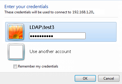
1. Use domain user test3 to log in to Host2, which has joined domain ldap.com.
Figure 88 Entering user credentials
2. After domain user test3 successfully logs in, view the number of online users on ADSSO.
Figure 89 AD Single Sign-On Service
3. Log in to the Web interface of the device, navigate to the Objects > User > User Management > Online Users page. View online users on the page.
Figure 90 Online Users

4. On Host2 logged in using user test3, ping external address 200.2.1.1. The address can be pinged successfully, indicating that user test3 can access the external network at 200.2.1.1.
C:\Users\test3>ping 200.2.1.1 –t
Pinging 200.2.1.1 with 32 bytes of data:
Reply from 200.2.1.1: bytes=32 time<1ms TTL=254
Reply from 200.2.1.1: bytes=32 time<1ms TTL=254
Reply from 200.2.1.1: bytes=32 time<1ms TTL=254
Reply from 200.2.1.1: bytes=32 time<1ms TTL=254
Reply from 200.2.1.1: bytes=32 time<1ms TTL=254
Reply from 200.2.1.1: bytes=32 time<1ms TTL=254
Reply from 200.2.1.1: bytes=32 time<1ms TTL=254
Verifying login of user test4
1. Log in to the Web interface of the device, and then navigate to the Policies > Security Policies > Security Policies page. Verify that the security policy only allows traffic from LDAP domain users test1 and test3.
Figure 91 Security policies

2. Use domain user test4 to log in to Host2, which has joined domain ldap.com.
Figure 92 Logging in using domain account
3. After domain user test4 successfully logs in, view the number of online users on ADSSO.
Figure 93 AD Single Sign-On Service

4. Log in to the Web interface of the device, navigate to the Objects > User > User Management > Online Users page. View online users on the page.
Figure 94 Online Users
5. Ping external address 200.2.1.1 from the Host2. The ping fails, indicating that user test4 cannot access the Internet.
C:\Users\test4>ping 200.2.1.1 –t
Pinging 200.2.1.1 with 32 bytes of data:
Request timed out
Request timed out
Request timed out
Request timed out
Request timed out
Request timed out
Request timed out
Verifying login of users test2 and test4 after the security policy permits packets of test2 and test4
1. Log in to the Web interface of the device, and then navigate to the Policies > Security Policies > Security Policies page. The policy only permit packets from users test1 and test3, so packets from users test2 and test4 will be discarded and cannot access the external network.
Figure 95 Security policies

2. To allow domain users test2 and test4 to access the external network at 200.2.1.1, add them to the security policy as shown in the figure below.
Figure 96 Security policies
3. Ping the external address 200.2.1.1 again on Host1. The ping succeeds, indicating that user test2 can also access the Internet.
C:\Users\test2>ping 200.2.1.1 –t
Pinging 200.2.1.1 with 32 bytes of data:
Reply from 200.2.1.1: bytes=32 time<1ms TTL=254
Reply from 200.2.1.1: bytes=32 time<1ms TTL=254
Reply from 200.2.1.1: bytes=32 time<1ms TTL=254
Reply from 200.2.1.1: bytes=32 time<1ms TTL=254
Reply from 200.2.1.1: bytes=32 time<1ms TTL=254
Reply from 200.2.1.1: bytes=32 time<1ms TTL=254
Reply from 200.2.1.1: bytes=32 time<1ms TTL=254
4. Ping the external address 200.2.1.1 again on Host2. The ping succeeds, indicating that user test4 can also access the Internet.
C:\Users\test4>ping 200.2.1.1 –t
Pinging 200.2.1.1 with 32 bytes of data:
Reply from 200.2.1.1: bytes=32 time<1ms TTL=254
Reply from 200.2.1.1: bytes=32 time<1ms TTL=254
Reply from 200.2.1.1: bytes=32 time<1ms TTL=254
Reply from 200.2.1.1: bytes=32 time<1ms TTL=254
Reply from 200.2.1.1: bytes=32 time<1ms TTL=254
Reply from 200.2.1.1: bytes=32 time<1ms TTL=254
Reply from 200.2.1.1: bytes=32 time<1ms TTL=254
Configuration files
#
interface GigabitEthernet1/0/1
ip address 192.168.1.1 255.255.255.0
#
interface GigabitEthernet1/0/2
ip address 200.1.1.1 255.255.255.0
#
security-zone name Trust
import interface GigabitEthernet1/0/1
#
security-zone name Untrust
import interface GigabitEthernet1/0/2
#
ip route-static 200.2.1.0 24 200.1.1.2
#
ldap server ldap1
login-dn cn=administrator,cn=users,dc=ldap,dc=com
search-base-dn dc=ldap,dc=com
ip 192.168.1.2
login-password simple Admin@1234
user-parameters user-name-format with-domain
#
ldap server ldap2
login-dn cn=administrator,cn=users,dc=ldap,dc=com
search-base-dn dc=ldap,dc=com
ip 192.168.1.3
login-password simple Admin@1234
user-parameters user-name-format with-domain
#
ldap scheme ldap1
authentication-server ldap1
attribute-map ldap
#
ldap scheme ldap2
authentication-server ldap2
attribute-map ldap
#
ldap attribute-map ldap
map ldap-attribute memberof prefix cn= delimiter , aaa-attribute user-group
#
local-user test class manage
password simple Admin@1234
RXBKiu46NOfqw==
service-type http
authorization-attribute user-role network-admin
authorization-attribute user-role network-operator
#
restful http enable
#
ip http enable
#
user-identity enable
user-identity user-account auto-import policy policy1
#
user-identity restful-server adsso
uri get-online-user http://192.168.1.4:8826/adsso/aduser/onlineUser
#
user-identity user-import-policy policy1
account-update-interval 1
restful-server adsso
ldap-scheme ldap1
ldap-scheme ldap2
#
security-policy ip
rule 1 name userlocalout1
action pass
source-zone local
destination-zone trust
source-ip-host 192.168.1.1
destination-ip-host 192.168.1.2
destination-ip-host 192.168.1.3
destination-ip-host 192.168.1.4
destination-ip-host 192.168.1.5
rule 2 name userlocalin1
action pass
source-zone trust
destination-zone local
source-ip-host 192.168.1.2
source-ip-host 192.168.1.3
source-ip-host 192.168.1.4
source-ip-host 192.168.1.5
destination-ip-host 192.168.1.1
rule 3 name trust-untrust
action pass
source-zone trust
destination-zone untrust
source-ip-subnet 192.168.1.0 255.255.255.0
destination-ip-host 200.2.1.1
user test1 domain ldap.com
user test3 domain ldap.com
rule 4 name untrust-trust
action pass
source-zone untrust
destination-zone trust
source-ip-host 200.2.1.1
destination-ip-subnet 192.168.1.0 255.255.255.0
#
RADIUS authentication service
Remote Authentication Dial-In User Service (RADIUS) is a distributed information interaction protocol that uses a client/server model. The protocol can protect networks against unauthorized access and is often used in network environments that require both high security and remote user access.
The RADIUS authorization process is combined with the RADIUS authentication process, and user authorization information is piggybacked in authentication responses. RADIUS uses UDP port 1812 for authentication and UDP port 1813 for accounting.
RADIUS was originally designed for dial-in user access, and has been extended to support additional access methods, such as Ethernet and ADSL.
Client/server model
The RADIUS client runs on the NASs located throughout the network. It passes user information to RADIUS servers and acts on the responses to, for example, reject or accept user access requests.
The RADIUS server runs on the computer or workstation at the network center and maintains information related to user authentication and network service access.
The RADIUS server operates using the following process:
1. Receives authentication, authorization, and accounting requests from RADIUS clients.
2. Performs user authentication, authorization, or accounting.
3. Returns user access control information (for example, rejecting or accepting the user access request) to the clients.
The RADIUS server can also act as the client of another RADIUS server to provide authentication proxy services.
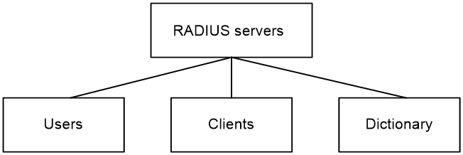
The RADIUS server maintains the following databases:
· Users—Stores user information, such as the usernames, passwords, applied protocols, and IP addresses.
· Clients—Stores information about RADIUS clients, such as shared keys and IP addresses.
· Dictionary—Stores RADIUS protocol attributes and their values.
Figure 97 RADIUS server databases
Information exchange security mechanism
The RADIUS client and server exchange information between them with the help of shared keys, which are preconfigured on the client and server. A RADIUS packet has a 16-byte field called Authenticator. This field includes a signature generated by using the MD5 algorithm, the shared key, and some other information. The receiver of the packet verifies the signature and accepts the packet only when the signature is correct. This mechanism ensures the security of information exchanged between the RADIUS client and server.
The shared keys are also used to encrypt user passwords that are included in RADIUS packets.
User authentication methods
The RADIUS server supports multiple user authentication methods, such as PAP, CHAP, and EAP.
Basic RADIUS packet exchange process
Figure 98 illustrates the interactions between a user host, the RADIUS client, and the RADIUS server.
Figure 98 Basic RADIUS packet exchange process
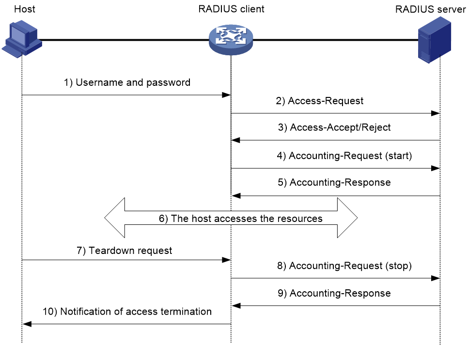
RADIUS uses in the following workflow:
1. The host sends a connection request that includes the user's username and password to the RADIUS client.
2. The RADIUS client sends an authentication request (Access-Request) to the RADIUS server. The request includes the user's password, which has been processed by the MD5 algorithm and shared key.
3. The RADIUS server authenticates the username and password. If the authentication succeeds, the server sends back an Access-Accept packet that contains the user's authorization information. If the authentication fails, the server returns an Access-Reject packet.
4. The RADIUS client permits or denies the user according to the authentication result. If the result permits the user, the RADIUS client sends a start-accounting request (Accounting-Request) packet to the RADIUS server.
5. The RADIUS server returns an acknowledgment (Accounting-Response) packet and starts accounting.
6. The user accesses the network resources.
7. The host requests the RADIUS client to tear down the connection.
8. The RADIUS client sends a stop-accounting request (Accounting-Request) packet to the RADIUS server.
9. The RADIUS server returns an acknowledgment (Accounting-Response) and stops accounting for the user.
10. The RADIUS client notifies the user of the termination.
RADIUS packet format
RADIUS uses UDP to transmit packets. The protocol also uses a series of mechanisms to ensure smooth packet exchange between the RADIUS server and the client. These mechanisms include the timer mechanism, the retransmission mechanism, and the backup server mechanism.
Figure 99 RADIUS packet format
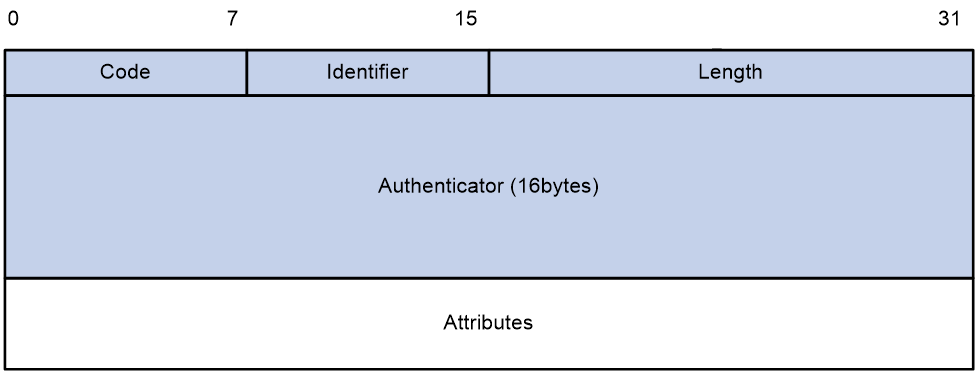
Descriptions of the fields are as follows:
· The Code field (1 byte long) indicates the type of the RADIUS packet. Table 6 gives the main values and their meanings.
Table 6 Main values of the Code field
|
Code |
Packet type |
Description |
|
1 |
Access-Request |
From the client to the server. A packet of this type includes user information for the server to authenticate the user. It must contain the User-Name attribute and can optionally contain the attributes of NAS-IP-Address, User-Password, and NAS-Port. |
|
2 |
Access-Accept |
From the server to the client. If all attribute values included in the Access-Request are acceptable, the authentication succeeds, and the server sends an Access-Accept response. |
|
3 |
Access-Reject |
From the server to the client. If any attribute value included in the Access-Request is unacceptable, the authentication fails, and the server sends an Access-Reject response. |
|
4 |
Accounting-Request |
From the client to the server. A packet of this type includes user information for the server to start or stop accounting for the user. The Acct-Status-Type attribute in the packet indicates whether to start or stop accounting. |
|
5 |
Accounting-Response |
From the server to the client. The server sends a packet of this type to notify the client that it has received the Accounting-Request and has successfully recorded the accounting information. |
· The Identifier field (1 byte long) is used to match response packets with request packets and to detect duplicate request packets. The request and response packets of the same exchange process for the same purpose (such as authentication or accounting) have the same identifier.
· The Length field (2 bytes long) indicates the length of the entire packet (in bytes), including the Code, Identifier, Length, Authenticator, and Attributes fields. Bytes beyond this length are considered padding and are ignored by the receiver. If the length of a received packet is less than this length, the packet is dropped.
· The Authenticator field (16 bytes long) is used to authenticate responses from the RADIUS server and to encrypt user passwords. There are two types of authenticators: request authenticator and response authenticator.
· The Attributes field (variable in length) includes authentication, authorization, and accounting information. This field can contain multiple attributes, each with the following subfields:
¡ Type—Type of the attribute.
¡ Length—Length of the attribute in bytes, including the Type, Length, and Value subfields.
¡ Value—Value of the attribute. Its format and content depend on the Type subfield.
Extended RADIUS attributes
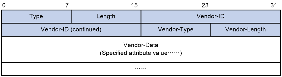
The RADIUS protocol features excellent extensibility. The Vendor-Specific attribute (attribute 26) allows a vendor to define extended attributes. The extended attributes can implement functions that the standard RADIUS protocol does not provide.
A vendor can encapsulate multiple subattributes in the TLV format in attribute 26 to provide extended functions. As shown in Figure 100, a subattribute encapsulated in attribute 26 consists of the following parts:
· Vendor-ID—ID of the vendor. The most significant byte is 0. The other three bytes contains a code compliant to RFC 1700.
· Vendor-Type—Type of the subattribute.
· Vendor-Length—Length of the subattribute.
· Vendor-Data—Contents of the subattribute.
Figure 100 Format of attribute 26
Example: Configuring user identification with RADIUS SSO authentication
Software versions used
This configuration example was created and verified on the following hardware and software:
|
Hardware/software |
Software version used |
|
F5000-AI160 (Device) |
E8371 |
|
MSR26-30 (Router) |
Version 7.1.064, ESS 0701 |
|
IMC (Portal server, RADIUS server) |
IMC PLAT 7.3 (E0506), IMC UAM 7.3 (E0503), IMC CAMS 7.3 (E0501), and IMC SSM 7.3 (E0501) |
Network configuration
As shown in Figure 101, the enterprise needs to perform identity identification and access control on portal users. The specific requirements are as follows:
· An IMC server acts as a portal authentication server, a portal Web server, and a RADIUS server.
· The RADIUS server acts as the authentication server.
· The RESTful server stores user account information.
· The router acts as a NAS to authenticate users. The users use static IP addresses and must pass portal authentication to access the network.
· The firewall (Device) performs the following identity-based access control on the users that have passed portal authentication:
¡ User user10001 cannot access the FTP server or the Internet.
¡ User user10002 can access the FTP server but cannot access the Internet.
¡ User user10003 can access the Internet but cannot access the FTP server.
¡ Users from the Internet cannot initiate access to the hosts in security zones trust and dmz.
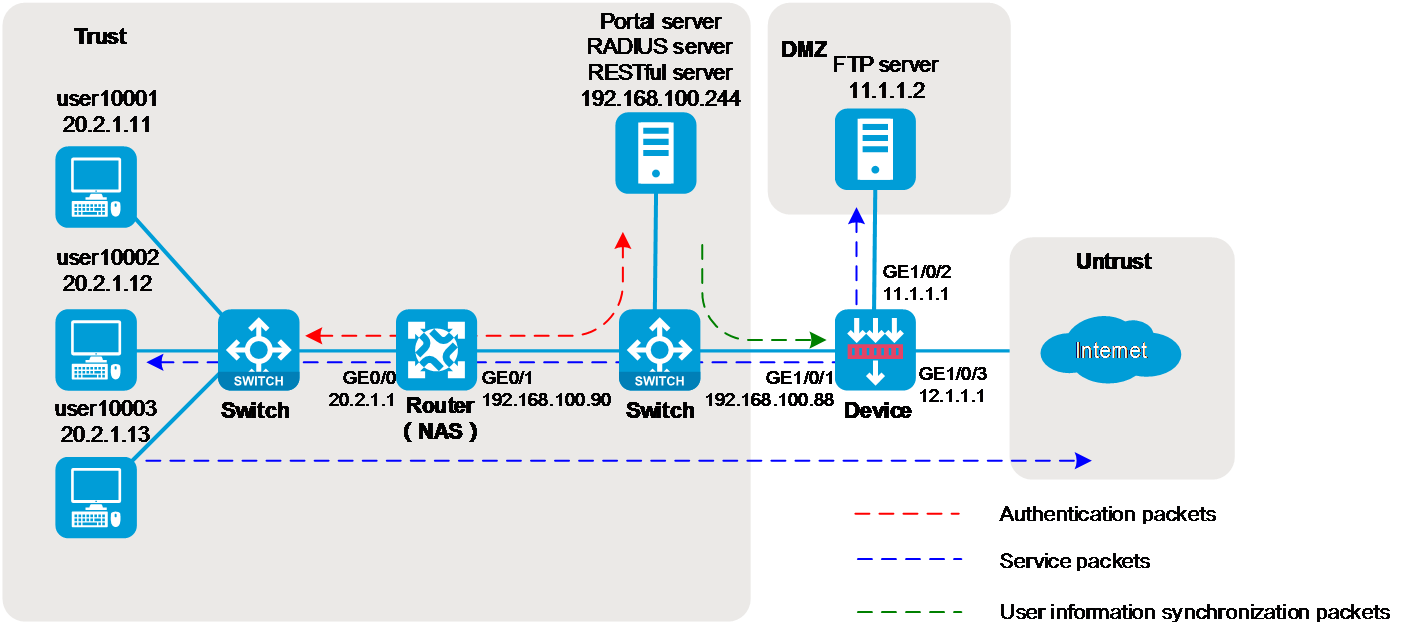
Analysis
To implement the purpose of this example, configure the hosts, router, firewall (Device), and IMC server as follows:
Figure 102 Analysis diagram
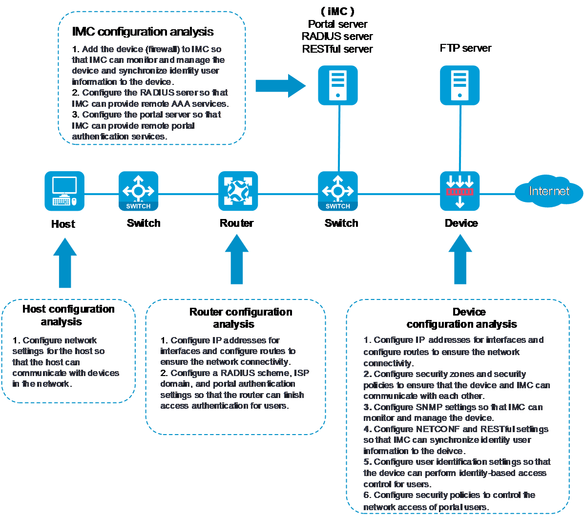
Restrictions and guidelines
An IMC server logs off an online user only if it receives an accounting-stop request for that user. For the NAS to send accounting-stop requests to the IMC server, you must configure accounting settings in the user authentication domain on the NAS. However, you do not need to configure accounting parameters on the IMC server because accounting is not required.
Procedures
Configuring the router
1. Configure IP addresses for interfaces and a default route to ensure the network connectivity of the router:
# Assign IP address 20.2.1.1 to interface GigabitEthernet 0/0.
<Router> system-view
[Router] interface gigabitethernet 0/0
[Router-GigabitEthernet0/0] ip address 20.2.1.1 255.255.255.0
[Router-GigabitEthernet0/0] quit
# Assign IP address 192.168.100.90 to interface GigabitEthernet 0/1.
[Router] interface gigabitethernet 0/1
[Router-GigabitEthernet0/1] ip address 192.168.100.90 255.255.255.0
[Router-GigabitEthernet0/1] quit
# Configure a default route to ensure that the router can reach the FTP server and the Internet.
[Router] ip route-static 0.0.0.0 0.0.0.0 192.168.100.88
2. Configure SNMP to ensure that the IMC server can monitor and manage the router:
# Enable the SNMP agent.
[Router] snmp-agent
# Enable all SNMP versions, and create the read-only community public and the read and write community private.
[Router] snmp-agent sys-info version all
[Router] snmp-agent community read public
[Router] snmp-agent community write private
3. Configure a RADIUS scheme:
# Create a RADIUS scheme named rs1 and enter its view.
[Router] radius scheme rs1
# Configure the primary authentication server, the primary accounting server, and the keys for secure communication.
[Router-radius-rs1] primary authentication 192.168.100.244
[Router-radius-rs1] primary accounting 192.168.100.244
[Router-radius-rs1] key authentication simple admin
# Exclude the ISP domain name from the usernames sent to the RADIUS server.
[Router-radius-rs1] user-name-format without-domain
[Router-radius-rs1] quit
4. Configure an authentication domain:
# Create an ISP domain named dm1 and enter its view.
[Router] domain dm1
# Configure users to use RADIUS scheme rs1 for authentication, authorization, and accounting in the ISP domain.
[Router-isp-dm1] authentication portal radius-scheme rs1
[Router-isp-dm1] authorization portal radius-scheme rs1
[Router-isp-dm1] accounting portal radius-scheme rs1
[Router-isp-dm1] quit
5. Configure portal authentication:
# Configure a portal authentication server named newpt, with IP address 192.168.100.244, plaintext password admin, and portal packet listening port number 50100.
[Router] portal server newpt
[Router-portal-server-newpt] ip 192.168.100.244 key simple admin
[Router-portal-server-newpt] port 50100
[Router-portal-server-newpt] quit
# Create a portal Web server named newpt and specify http://192.168.100.244:8080/portal as the URL of the server.
[Router] portal web-server newpt
[Router-portal-websvr-newpt] url http://192.168.100.244:8080/portal
[Router-portal-websvr-newpt] quit
# Enable direct portal authentication on GigabitEthernet 0/0.
[Router] interface gigabitethernet 0/0
[Router–GigabitEthernet0/0] portal enable method direct
# Specify portal Web server newpt on GigabitEthernet 0/0.
[Router–GigabitEthernet0/0] portal apply web-server newpt
# Specify domain dm1 as the portal authentication domain on GigabitEthernet 0/0.
[Router–GigabitEthernet0/0] portal domain dm1
[Router–GigabitEthernet0/0] quit
Configuring the firewall (Device)
1. Configure IP addresses for interfaces and a default route to ensure the network connectivity of the firewall:
# Assign IP address 192.168.100.88 to interface GigabitEthernet 1/0/1.
<Device> system-view
[Device] interface gigabitethernet 1/0/1
[Device-GigabitEthernet1/0/1] ip address 192.168.100.88 255.255.255.0
[Device-GigabitEthernet1/0/1] quit
# Assign IP address 11.1.1.1 to interface GigabitEthernet 1/0/2.
[Device] interface gigabitethernet 1/0/2
[Device-GigabitEthernet1/0/2] ip address 11.1.1.1 255.255.255.0
[Device-GigabitEthernet1/0/2] quit
# Assign IP address 12.1.1.1 to interface GigabitEthernet 1/0/3.
[Device] interface gigabitethernet 1/0/3
[Device-GigabitEthernet1/0/3] ip address 12.1.1.1 255.255.255.0
[Device-GigabitEthernet1/0/3] quit
# Configure a static route to ensure that the firewall can reach the user network.
[Device] ip route-static 20.2.1.0 255.255.255.0 192.168.100.90
# Configure a default route to ensure that the firewall can reach the Internet. This example uses 12.1.1.2 as the IP address of the next hop for the route. In an actual network, use the IP address provided by the ISP.
[Device] ip route-static 0.0.0.0 0.0.0.0 12.1.1.2
2. Add interfaces to security zones:
# Create security zone trust and enter its view. Add interface GigabitEthernet 1/0/1 to the security zone.
[Device] security-zone name trust
[Device-security-zone-Trust] import interface gigabitethernet 1/0/1
[Device-security-zone-Trust] quit
# Create security zone dmz and enter its view. Add interface GigabitEthernet 1/0/2 to the security zone.
[Device] security-zone name dmz
[Device-security-zone-DMZ] import interface gigabitethernet 1/0/2
[Device-security-zone-DMZ] quit
# Create security zone untrust and enter its view. Add interface GigabitEthernet 1/0/3 to the security zone.
[Device] security-zone name untrust
[Device-security-zone-Untrust] import interface gigabitethernet 1/0/3
[Device-security-zone-Untrust] quit
3. Configure a security policy to ensure that the firewall and IMC can reach each other.
This step ensures that the firewall can synchronize user identity information from IMC.
# Enter IPv4 security policy view.
[Device] security-policy ip
# Configure a rule named trust-local to permit packets from security zone trust to security zone local.
[Device-security-policy-ip] rule 0 name trust-local
[Device-security-policy-ip-0-trust-local] source-zone trust
[Device-security-policy-ip-0-trust-local] destination-zone local
[Device-security-policy-ip-0-trust-local] action pass
[Device-security-policy-ip-0-trust-local] quit
# Configure a rule named local-trust to permit packets from security zone local to security zone trust.
[Device-security-policy-ip] rule 1 name local-trust
[Device-security-policy-ip-1-trust-local] source-zone local
[Device-security-policy-ip-1-trust-local] destination-zone trust
[Device-security-policy-ip-1-trust-local] action pass
[Device-security-policy-ip-1-trust-local] quit
4. Configure SNMP for the IMC server to monitor and manage the firewall.
# Enable the SNMP agent.
[Device] snmp-agent
# Enable all SNMP versions, and create the read-only community public and the read and write community private.
[Device] snmp-agent sys-info version all
[Device] snmp-agent community read public
[Device] snmp-agent community write private
5. Configure NETCONF over SOAP for the IMC server to issue configuration to the firewall:
# Enable NETCONF over SOAP over HTTP.
[Device] netconf soap http enable
# Enable NETCONF over SOAP over HTTPS.
[Device] netconf soap https enable
6. Enable RESTful for the firewall for communication with the IMC server:
# Enable RESTful access over HTTP.
[Device] restful http enable
# Enable RESTful access over HTTPS.
[Device] restful https enable
7. Configure the HTTP service for local device management user admin.
[Device] local-user admin class manage
[Device-luser-manage-admin] service-type http
[Device-luser-manage-admin] quit
8. Configure the user identification feature:
# Enable the user identification feature.
[Device] user-identity enable
# Create a RESTful server named rest1 and enter its view.
[Device] user-identity restful-server rest1
# Specify the username and password for logging in to the RESTful server as both admin.
[Device-restfulserver-rest1] login-name admin password simple admin
# Specify the URIs for requesting information such as the network access user account information and online network access user information from the RESTful server. (The URIs of the IMC server are fixed as follows. Only the IP address can be replaced.)
[Device-restfulserver-rest1] uri get-user-database http://192.168.100.244:8080/imcrs/ssm/imcuser/accessUser
[Device-restfulserver-rest1] uri get-user-group-database http://192.168.100.244:8080/imcrs/ssm/imcuser/acces
sUserGroup
[Device-restfulserver-rest1] uri get-online-user http://192.168.100.244:8080/imcrs/ssm/imcuser/onlineUser
[Device-restfulserver-rest1] uri put-online-user http://192.168.100.244:8080/imcrs/ssm/imcuser/uploadOnlineU
ser
[Device-restfulserver-rest1] uri put-offline-user http://192.168.100.244:8080/imcrs/ssm/imcuser/uploadOfflin
eUser
[Device-restfulserver-rest1] quit
# Create an identity user import policy named imc and enter its view.
[Device] user-identity user-import-policy imc
# Specify RESTful server rest1 for the identity user import policy.
[Device-identity-user-impt-policy-imc] restful-server rest1
# Set the interval for automatic identity user account import to 1 hour.
[Device-identity-user-impt-policy-imc] account-update-interval 1
[Device-identity-user-impt-policy-imc] quit
# Enable automatic identity user account import.
[Device] user-identity user-account auto-import policy imc
# Import identity user accounts from the servers specified in identity user import policy imc. (Execute this command after the device can communicate normally with the IMC server.)
[Device] user-identity user-account import policy imc
# Import online identity users from the servers specified in identity user import policy imc. (Execute this command after the device can communicate normally with the IMC server and users have come online.)
[Device] user-identity online-user import policy imc
9. Configure a security policy to permit only user10002 to access the FTP server and permit only user10003 to access the Internet:
# Configure a security policy rule named user10002 to permit only user10002 to communicate with the FTP server and deny others from accessing the FTP server.
[Device] security-policy ip
[Device-security-policy-ip] rule 2 name user10002
[Device-security-policy-ip-2-user10002] source-zone trust
[Device-security-policy-ip-2-user10002] source-zone dmz
[Device-security-policy-ip-2-user10002] destination-zone dmz
[Device-security-policy-ip-2-user10002] destination-zone trust
[Device-security-policy-ip-2-user10002] user user10002
[Device-security-policy-ip-2-user10002] action pass
[Device-security-policy-ip-2-user10002] logging enable
[Device-security-policy-ip-2-user10002] quit
# Configure a security policy rule named user10003 to permit only user10003 to access the Internet and deny Internet users from accessing the internal network.
[Device-security-policy-ip] rule 3 name user10003
[Device-security-policy-ip-3-user10003] source-zone trust
[Device-security-policy-ip-3-user10003] destination-zone untrust
[Device-security-policy-ip-3-user10003] user user10003
[Device-security-policy-ip-3-user10003] action pass
[Device-security-policy-ip-2-user10003] logging enable
[Device-security-policy-ip-3-user10003] quit
[Device-security-policy-ip] quit
Adding devices to IMC
Add the firewall to IMC for device monitoring and management.
1. Enter the URL of IMC in the address bar of a browser to log in to IMC.
In this example, the URL for IMC is http://192.168.100.244:8080/imc/. The username and password are both admin. (Details not shown.)
2. Adding the firewall:
# Click the Resource tab.
# From the navigation pane, select Resource Management > Add Device.
# On the page that opens, configure the parameters as shown in Figure 103:
¡ In the Telnet Settings area, set both the username and password to admin.
¡ Use the default settings for other parameters.
By default, the read-only SNMP community string is public and the read and write SNMP community string is private.
Figure 103 Adding the firewall

# Click OK.
# Add the router at 192.168.100.90 to IMC in the same way.
3. Modify NETCONF settings:
# Click the Resource tab.
# From the navigation pane, select View Management > Device View.
# Click the link in the firewall Label column for the target device.
Figure 104 Device list
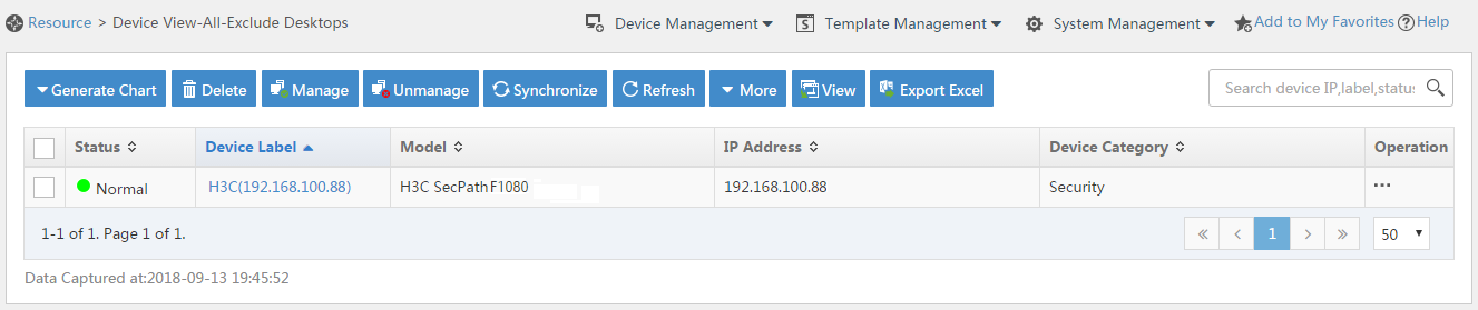
# In the right pane, click Configure > Modify NETCONF Settings.
# In the dialog box that opens, click the plus sign (+) to add a protocol as shown in Figure 105.
This example sets both the username and password to admin.
Figure 105 Modifying NETCONF settings

# Click OK.
Configuring security services on IMC
1. Synchronize security services from the firewall to the IMC server to ensure that the configuration and user information is consistent on the firewall and IMC server:
# Click the Service tab.
# From the navigation pane, select Security Service Manager > Device Management.
# On the Devices tab, view the firewall displayed in the device list.
Figure 106 Device management page (1)
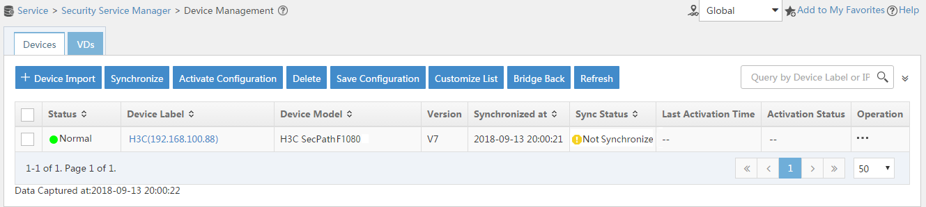
# Select the firewall, click Synchronize, and then view the synchronization status in the Sync Status column.
The synchronization process might take a long time. Please wait.
Figure 107 Device management page (2)

Figure 108 Device management page (3)

2. Configure user authentication system parameters and user notification parameters to ensure that the IMC server synchronizes user online and offline information to the firewall in real time:
# Click the Service tab.
# From the navigation pane, select Security Service Manager > Global Parameters.
# Configure the user authentication system parameters, and then click OK.
¡ Select a protocol based on the protocol type of the portal authentication server.
¡ The username and password must be the same as those configured on the router for logging in to the IMC server.
Figure 109 Configuring user authentication system parameters
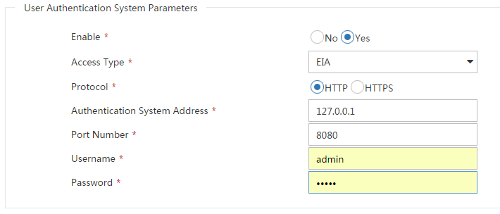
# Click the User tab.
# From the navigation pane, select User Access Policy > Service Parameters > System Settings.
# Click the Configure icon for User Notification Parameters.
# Click Add.
# On the page that opens, configure the parameters as needed, and then click OK.
Because no shared key is used in this example, you can enter a shared key randomly.
Figure 110 Configuring user notification parameters

Configuring the RADIUS server on IMC
1. Enter the URL of IMC in the address bar of a browser to log in to IMC.
In this example, the URL for IMC is http://192.168.100.244:8080/imc/. The username and password are both admin. (Details not shown.)
2. Add the router to IMC as an access device:
# Click the User tab.
# From the navigation pane, select User Access Policy > Access Device Management > Access Device.
# Click Add.
# Set the shared key to admin, and configure other parameters as needed.
Figure 111 Adding an access device
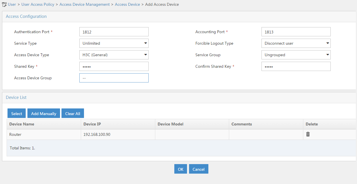
# Click OK.
|
|
NOTE: The IP address of the access device specified on IMC must be the source IP address of outgoing RADIUS packets specified on the router. By default, if no source IP address is specified for outgoing RADIUS packets, the IP address of the packet outgoing interface is used. · If you have executed the nas-ip or radius nas-ip command on the router to specify a source IP address for outgoing RADIUS packets, you must configure the specified address as the IP address of the access device. · In this example, the IP address 192.168.100.90 of the packet outgoing interface is used as the IP address of the access device. |
3. Add an access policy:
# Click the User tab.
# From the navigation pane, select User Access Policy > Access Policy.
# Click Add.
# Set the access policy name to Portal, and use the default settings for other parameters.
Figure 112 Adding an access policy
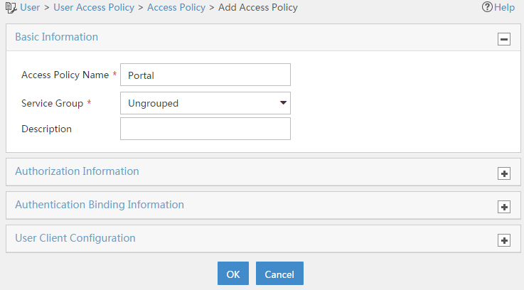
# Click OK.
4. Add an access service:
# Click the User tab.
# From the navigation pane, select User Access Policy > Access Service.
# Click Add.
# On the page that opens, configure the following parameters:
¡ Specify the service name as Portal.
¡ Select Portal from the Default Access Policy list.
Figure 113 Adding an access service

# Click OK.
5. Add an access user:
# Click the User tab.
# From the navigation pane, select Access User > All Access Users.
# Click Add.
# On the page that opens, configure the following parameters:
¡ Enter user in the User Name field.
¡ Enter user10001 in the Account Name field.
¡ Enter admin in the Password and Confirm Password fields.
¡ Select Portal in the Access Service area.
Figure 114 Adding an access user
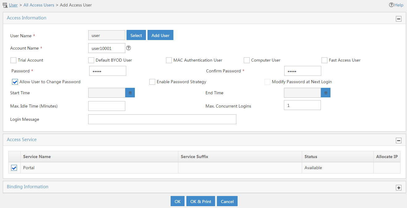
# Click OK.
# Add user accounts user10002 and user10003 in the same way.
Configuring the portal server on IMC
1. Enter the URL of IMC in the address bar of a browser to log in to IMC.
In this example, the URL for IMC is http://192.168.100.244:8080/imc/. The username and password are both admin. (Details not shown.)
2. Configure the portal server:
# Click the User tab.
# From the navigation pane, select User Access Policy > Portal Service > Server.
# Configure the portal server parameters as needed. This example uses the default settings.
Figure 115 Configuring the portal server

3. Add an IP group:
# Click the User tab.
# From the navigation pane, select User Access Policy > Portal Service > IP Group.
# Click Add.
# Configure the parameters as needed.
Figure 116 Adding an IP group
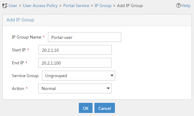
# Click OK.
4. Add a portal device:
# Click the User tab.
# From the navigation pane, select User Access Policy > Portal Service > Device.
# Click Add.
# Set the shared key to admin and configure other parameters as shown in Figure 117.
Figure 117 Adding a portal device
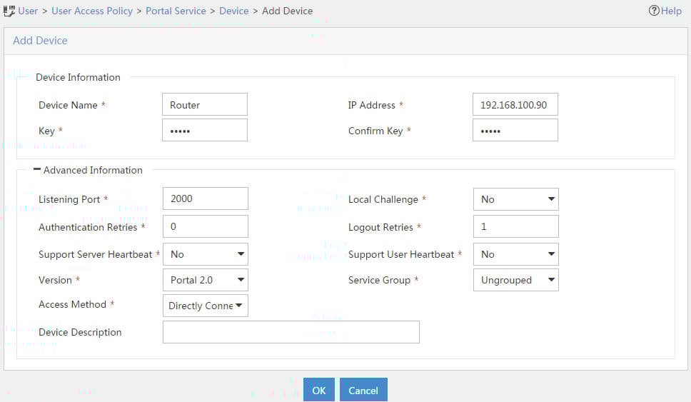
# Click OK.
5. Associate the portal device with the IP group:
# Click the User tab.
# From the navigation pane, select User Access Policy > Portal Service > Device.
# Click the Port Group icon in the Operation column for the router.
Figure 118 Device list
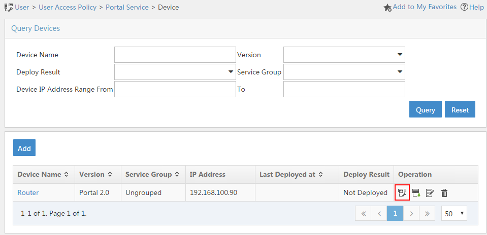
# Click Add.
# Configure the parameters as needed.
Figure 119 Adding a port group
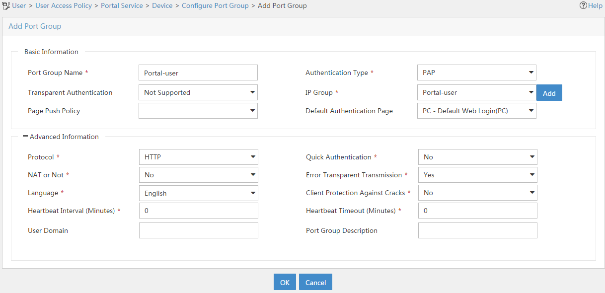
# Click OK.
Configuring the hosts
Configure the IP address, subnet mask, and default gateway settings on each host. Make sure the hosts can communicate with other devices on the network. (Details not shown.)
Verifying the configuration
1. On the hosts, verify that the users can pass portal authentication:
# Enter the URL of the portal Web server in the address bar of a browser.
In this example, the URL is http://192.168.100.244:8080/portal.
# Enter the username and password.
# Click Log In.
# Verify that the user has passed portal authentication.
Figure 120 Portal authentication success page
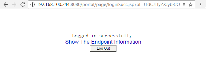
2. On the IMC server, verify that you can view users user10001, user10002, and user10003 on the online user list of the User > Access User > Online Users page.
3. On the firewall, view identity user information:
# View information about all identity users.
[Device] display user-identity all user
User ID Username
0x2 user10001
0x3 user10002
0x4 user10003
# View information about online identity user user10001.
[Device] display user-identity online-user null-domain name user10001
User name: user10001
IP : 20.2.1.11
MAC : 0011-95e4-4aa9
Type: Dynamic
Total 1 records matched.
# View information about online identity user user10002.
[Device] display user-identity online-user null-domain name user10002
User name: user10002
IP : 20.2.1.12
MAC : 0011-95e4-4aa3
Type: Dynamic
Total 1 records matched.
# View information about online identity user user10003.
[Device] display user-identity online-user null-domain name user10003
User name: user10003
IP : 20.2.1.13
MAC : 0011-95e4-4aa2
Type: Dynamic
Total 1 records matched.
4. Verify that the firewall can perform identity-based access control on the users:
# Verify that user user10001 cannot ping the FTP server.
C:\>ping 11.1.1.2
Pinging 11.1.1.2 with 32 bytes of data:
Request time out.
Request time out.
Request time out.
Request time out.
Ping statistics for 11.1.1.2:
Packets: Sent = 4, Received = 0, Lost = 4 (100% loss),
# Verify that user user10002 can ping the FTP server.
C:\>ping 11.1.1.2
Pinging 11.1.1.2 with 32 bytes of data:
Reply from 11.1.1.2: bytes=32 time=36ms TTL=253
Reply from 11.1.1.2: bytes=32 time<1ms TTL=253
Reply from 11.1.1.2: bytes=32 time<1ms TTL=253
Reply from 11.1.1.2: bytes=32 time<1ms TTL=253
Ping statistics for 11.1.1.2:
Packets: Sent = 4, Received = 4, Lost = 0 (0% loss),
Approximate round trip times in milli-seconds:
Minimum = 0ms, Maximum = 36ms, Average = 9ms
# When user user10002 pings the FTP server, verify that the firewall generates a log as follows.
[Device]%Nov 6 10:19:53:920 2017 H3C FILTER/6/FILTER_ZONE_EXECUTION_ICMP: -Context
=1; SrcZoneName(1025)=Trust;DstZoneName(1035)=DMZ;Type(1067)=ACL;SecurityPolicy(
1072)=user10002;RuleID(1078)=2;Protocol(1001)=ICMP;SrcIPAddr(1003)=20.2.1.12;Src
MacAddr(1021)=7425-8a37-b5f6;DstIPAddr(1007)=11.1.1.2;IcmpType(1062)=ECHO(8);Icm
pCode(1063)=0;MatchCount(1069)=1;Event(1048)=Permit;
# Verify that user user10003 can ping hosts on the Internet.
In this example, the user pings the host at 12.1.1.2.
C:\>ping 12.1.1.2
Pinging 12.1.1.2 with 32 bytes of data:
Reply from 12.1.1.2: bytes=32 time=37ms TTL=253
Reply from 12.1.1.2: bytes=32 time<1ms TTL=253
Reply from 12.1.1.2: bytes=32 time<1ms TTL=253
Reply from 12.1.1.2: bytes=32 time<1ms TTL=253
Ping statistics for 12.1.1.2:
Packets: Sent = 4, Received = 4, Lost = 0 (0% loss),
Approximate round trip times in milli-seconds:
Minimum = 0ms, Maximum = 36ms, Average = 9ms
# When user user10003 pings the host on the Internet, verify that the firewall generates a log as follows.
[Device]%Nov 6 10:19:53:920 2017 H3C FILTER/6/FILTER_ZONE_EXECUTION_ICMP: -Context
=1; SrcZoneName(1025)=Trust;DstZoneName(1035)=Untrust;Type(1067)=ACL;SecurityPolicy(
1072)=user10003;RuleID(1078)=3;Protocol(1001)=ICMP;SrcIPAddr(1003)=20.2.1.13;Src
MacAddr(1021)=7425-8a37-b5f6;DstIPAddr(1007)=12.1.1.2;IcmpType(1062)=ECHO(8);Icm
pCode(1063)=0;MatchCount(1069)=1;Event(1048)=Permit;
Configuration files
Router
[Router] display current-configuration
#
interface GigabitEthernet0/0
port link-mode route
ip address 20.2.1.1 255.255.255.0
portal enable method direct
portal domain dm1
portal apply web-server newpt
#
interface GigabitEthernet0/1
port link-mode route
ip address 192.168.100.90 255.255.255.0
#
interface GigabitEthernet3/0
port link-mode route
combo enable copper
#
ip route-static 0.0.0.0 0 192.168.100.88
#
snmp-agent
snmp-agent local-engineid 800063A28074258A37B5F500000001
snmp-agent community write private
snmp-agent community read public
snmp-agent sys-info version all
#
radius scheme rs1
primary authentication 192.168.100.244
primary accounting 192.168.100.244
key authentication cipher $c$3$hhbEbD5Ycvw7VWqljAoMoU7hQRgcUjtg
user-name-format without-domain
#
domain dm1
authentication portal radius-scheme rs1
authorization portal radius-scheme rs1
accounting portal radius-scheme rs1
#
domain system
#
domain default enable system
#
local-user admin class manage
password hash $h$6$UbIhNnPevyKUwfpm$LqR3+yg1IjNct39MkOR0H0iQXLkYB3jMqM4vbAeoXOh
babIIFnjJPEGR00YiYA1Sz4LiY3FmEdru2fOLMb1shQ==
service-type telnet http
authorization-attribute user-role network-admin
#
portal web-server newpt
url http://192.168.100.244:8080/portal
#
portal server newpt
ip 192.168.100.244 key cipher $c$3$+UmaGOco7eHsjOqlrp8lI4eYe0A8NpYU
#
return
Device
[Device] display current-configuration
#
interface GigabitEthernet1/0/1
port link-mode route
ip address 192.168.100.88 255.255.255.0
#
interface GigabitEthernet1/0/2
port link-mode route
ip address 11.1.1.1 255.255.255.0
#
interface GigabitEthernet1/0/3
port link-mode route
ip address 12.1.1.1 255.255.255.0
#
security-zone name Trust
import interface GigabitEthernet1/0/1
#
security-zone name DMZ
import interface GigabitEthernet1/0/2
#
security-zone name Untrust
import interface GigabitEthernet1/0/3
#
line vty 0 63
authentication-mode scheme
user-role network-admin
#
ip route-static 0.0.0.0 0 12.1.1.2
ip route-static 20.2.1.0 24 192.168.100.90
#
snmp-agent
snmp-agent local-engineid 800063A280487ADA9593B700000001
snmp-agent community write private
snmp-agent community read public
snmp-agent sys-info version all
snmp-agent target-host trap address udp-domain 192.168.100.244 params securityn
ame public v2c
#
local-user admin class manage
password hash $h$6$UbIhNnPevyKUwfpm$LqR3+yg1IjNct39MkOR0H0iQXLkYB3jMqM4vbAeoXOh
babIIFnjJPEGR00YiYA1Sz4LiY3FmEdru2fOLMb1shQ==
service-type ssh telnet terminal http https
authorization-attribute user-role level-3
authorization-attribute user-role network-admin
authorization-attribute user-role network-operator
#
netconf soap http enable
netconf soap https enable
restful http enable
restful https enable
#
user-identity enable
user-identity user-account auto-import policy imc
#
user-identity restful-server rest1
login-name admin password cipher $c$3$phGy00HA6OP6pIpGI0KOKZEOPuLVbtt/
uri get-user-database http://192.168.100.244:8080/imcrs/ssm/imcuser/accessUser
uri get-user-group-database http://192.168.100.244:8080/imcrs/ssm/imcuser/acces
sUserGroup
uri get-online-user http://192.168.100.244:8080/imcrs/ssm/imcuser/onlineUser
uri put-online-user http://192.168.100.244:8080/imcrs/ssm/imcuser/uploadOnlineU
ser
uri put-offline-user http://192.168.100.244:8080/imcrs/ssm/imcuser/uploadOfflin
eUser
#
user-identity user-import-policy imc
account-update-interval 1
restful-server rest1
#
security-policy ip
rule 0 name trust-local
action pass
source-zone trust
destination-zone local
rule 1 name local-trust
action pass
source-zone local
destination-zone trust
rule 2 name user10002
action pass
logging enable
source-zone trust
source-zone dmz
destination-zone dmz
destination-zone trust
user user10002
rule 3 name user10003
action pass
logging enable
source-zone trust
destination-zone untrust
user user10003
#
return
Example: Configuring user identification with RADIUS authentication (local access)
Software versions used
This configuration example was created and verified on the following hardware and software:
|
Hardware/software |
Software version used |
|
F5000-AI160 (Device) |
E8371 |
|
MSR26-30 (Router) |
Version 7.1.064, ESS 0701 |
|
IMC (Portal server, RADIUS server) |
IMC PLAT 7.3 (E0506), IMC UAM 7.3 (E0503), IMC CAMS 7.3 (E0501), and IMC SSM 7.3 (E0501) |
Network configuration
As shown in Figure 121, the enterprise needs to perform identity identification and access control on portal users. The specific requirements are as follows:
· An IMC server acts as a portal authentication server, a portal Web server, and a RADIUS server.
· The RADIUS server acts as the authentication server.
· The RESTful server stores user account information.
· The firewall (Device) acts as a NAS to authenticate users. The users use static IP addresses and must pass portal authentication to access the network.
· The firewall (Device) performs the following identity-based access control on the users that have passed portal authentication:
¡ Users user10001 and user10002 cannot access the Internet.
¡ User user10003 can access the Internet.
¡ Users from the Internet cannot access the hosts in security zones trust and dmz.
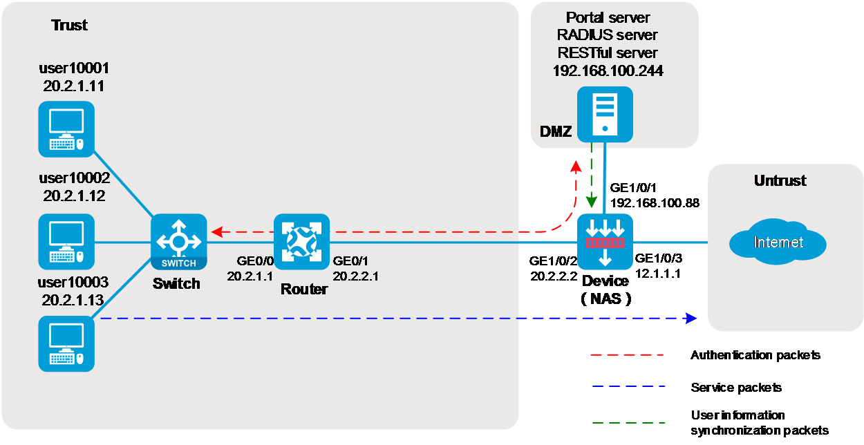
Analysis
To implement the purpose of this example, configure the hosts, router, firewall (Device), and IMC server as follows:
Figure 122 Analysis diagram

Restrictions and guidelines
An IMC server logs off an online user only if it receives an accounting-stop request for that user. For the NAS to send accounting-stop requests to the IMC server, you must configure accounting in the user authentication domain on the NAS. However, you do not need to configure accounting parameters on the IMC server because accounting is not required.
Procedures
Configuring the router
Configure IP addresses for interfaces and a default route to ensure the network connectivity of the router:
# Assign IP address 20.2.1.1 to interface GigabitEthernet 0/0.
<Router> system-view
[Router] interface gigabitethernet 0/0
[Router-GigabitEthernet0/0] ip address 20.2.1.1 255.255.255.0
[Router-GigabitEthernet0/0] quit
# Assign IP address 20.2.2.1 to interface GigabitEthernet 0/1.
[Router] interface gigabitethernet 0/1
[Router-GigabitEthernet0/1] ip address 20.2.2.1 255.255.255.0
[Router-GigabitEthernet0/1] quit
# Configure a default route to ensure that the router can reach the FTP server and the Internet.
[Router] ip route-static 0.0.0.0 0.0.0.0 20.2.2.2
Configuring the firewall (Device)
1. Configure IP addresses for interfaces and a default route to ensure the network connectivity of the router:
# Assign IP address 192.168.100.88 to interface GigabitEthernet 1/0/1.
<Device> system-view
[Device] interface gigabitethernet 1/0/1
[Device-GigabitEthernet1/0/1] ip address 192.168.100.88 255.255.255.0
[Device-GigabitEthernet1/0/1] quit
# Assign IP address 20.2.2.2 to interface GigabitEthernet 1/0/2.
[Device] interface gigabitethernet 1/0/2
[Device-GigabitEthernet1/0/2] ip address 20.2.2.2 255.255.255.0
[Device-GigabitEthernet1/0/2] quit
# Assign IP address 12.1.1.1 to interface GigabitEthernet 1/0/3.
[Device] interface gigabitethernet 1/0/3
[Device-GigabitEthernet1/0/3] ip address 12.1.1.1 255.255.255.0
[Device-GigabitEthernet1/0/3] quit
# Configure a static route to ensure that the firewall can reach the user network.
[Device] ip route-static 20.2.1.0 255.255.255.0 20.2.2.1
# Configure a default route to ensure that the firewall can reach the Internet.
This example uses 12.1.1.2 as the IP address of the next hop for the route. In an actual network, use the IP address provided by the ISP.
[Device] ip route-static 0.0.0.0 0.0.0.0 12.1.1.2
2. Add interfaces to security zones.
# Create security zone dmz and enter its view. Add interface GigabitEthernet 1/0/1 to the security zone.
[Device] security-zone name dmz
[Device-security-zone-DMZ] import interface gigabitethernet 1/0/1
[Device-security-zone-DMZ] quit
# Create security zone trust and enter its view. Add interface GigabitEthernet 1/0/2 to the security zone.
[Device] security-zone name trust
[Device-security-zone-Trust] import interface gigabitethernet 1/0/2
[Device-security-zone-Trust] quit
# Create security zone untrust and enter its view. Add interface GigabitEthernet 1/0/3 to the security zone.
[Device] security-zone name untrust
[Device-security-zone-Untrust] import interface gigabitethernet 1/0/3
[Device-security-zone-Untrust] quit
3. Configure a security policy to ensure that the firewall and IMC can reach each other.
This step ensures that the firewall can synchronize user identity information from IMC.
# Enter IPv4 security policy view.
[Device] security-policy ip
# Configure a rule named dmz-local to permit packets from security zone dmz to security zone local.
[Device-security-policy-ip] rule 0 name dmz-local
[Device-security-policy-ip-0-dmz-local] source-zone dmz
[Device-security-policy-ip-0-dmz-local] destination-zone local
[Device-security-policy-ip-0-dmz-local] action pass
[Device-security-policy-ip-0-dmz-local] quit
# Configure a rule named local-dmz to permit packets from security zone local to security zone dmz.
[Device-security-policy-ip] rule 1 name local-dmz
[Device-security-policy-ip-1-dmz-local] source-zone local
[Device-security-policy-ip-1-dmz-local] destination-zone dmz
[Device-security-policy-ip-1-dmz-local] action pass
[Device-security-policy-ip-1-dmz-local] quit
4. Configure a security policy to ensure network connectivity between security zones trust and dmz so that the user network and IMC can reach each other:
Because the portal authentication packets traverse the firewall, you must configure this step to ensure that portal users can perform AAA and portal authentication by the IMC.
# Configure a security policy rule named trust-dmz to permit packets between security zones trust and dmz.
[Device] security-policy ip
[Device-security-policy-ip] rule 2 name trust-dmz
[Device-security-policy-ip-2-trust-dmz] source-zone trust
[Device-security-policy-ip-2-trust-dmz] source-zone dmz
[Device-security-policy-ip-2-trust-dmz] destination-zone dmz
[Device-security-policy-ip-2-trust-dmz] destination-zone trust
[Device-security-policy-ip-2-trust-dmz] action pass
[Device-security-policy-ip-2-trust-dmz] quit
5. Configure SNMP for the IMC server to monitor and manage the firewall:
# Enable the SNMP agent.
[Device] snmp-agent
# Enable all SNMP versions, and create the read-only community public and the read and write community private.
[Device] snmp-agent sys-info version all
[Device] snmp-agent community read public
[Device] snmp-agent community write private
6. Configure NETCONF over SOAP for the IMC server to issue configuration to the firewall:
# Enable NETCONF over SOAP over HTTP.
[Device] netconf soap http enable
# Enable NETCONF over SOAP over HTTPS.
[Device] netconf soap https enable
7. Enable RESTful for the firewall for communication with the IMC server:
# Enable RESTful access over HTTP.
[Device] restful http enable
# Enable RESTful access over HTTPS.
[Device] restful https enable
8. Configure the HTTP service for local device management user admin.
[Device] local-user admin class manage
[Device-luser-manage-admin] service-type http
[Device-luser-manage-admin] quit
9. Configure a RADIUS scheme:
# Create a RADIUS scheme named rs1 and enter its view.
[Device] radius scheme rs1
# Configure the primary authentication server, the primary accounting server, and the keys for secure communication.
[Device-radius-rs1] primary authentication 192.168.100.244
[Device-radius-rs1] primary accounting 192.168.100.244
[Device-radius-rs1] key authentication simple admin
# Exclude the ISP domain name from the usernames sent to the RADIUS server.
[Device-radius-rs1] user-name-format without-domain
[Device-radius-rs1] quit
10. Configure an authentication domain:
# Create an ISP domain named dm1 and enter its view.
[Device] domain dm1
# Configure users to use RADIUS scheme rs1 for authentication, authorization, and accounting in the ISP domain.
[Device-isp-dm1] authentication portal radius-scheme rs1
[Device-isp-dm1] authorization portal radius-scheme rs1
[Device-isp-dm1] accounting portal radius-scheme rs1
[Device-isp-dm1] quit
11. Configure portal authentication:
# Configure a portal authentication server named newpt, with IP address 192.168.100.244, plaintext password admin, and portal packet listening port number 50100.
[Device] portal server newpt
[Device-portal-server-newpt] ip 192.168.100.244 key simple admin
[Device-portal-server-newpt] port 50100
[Device-portal-server-newpt] quit
# Create a portal Web server named newpt and specify http://192.168.100.244:8080/portal as the URL of the server.
[Device] portal web-server newpt
[Device-portal-websvr-newpt] url http://192.168.100.244:8080/portal
[Device-portal-websvr-newpt] quit
# Enable cross-subnet portal authentication on GigabitEthernet 1/0/2.
[Device] interface gigabitethernet 1/0/2
[Device–GigabitEthernet1/0/2] portal enable method layer3
# Specify portal Web server newpt on GigabitEthernet 1/0/2.
[Device–GigabitEthernet1/0/2] portal apply web-server newpt
# Specify domain dm1 as the portal authentication domain on GigabitEthernet 1/0/2.
[Device–GigabitEthernet1/0/2] portal domain dm1
[Device–GigabitEthernet1/0/2] quit
12. Configure the user identification feature:
# Enable the user identification feature.
[Device] user-identity enable
# Create a RESTful server named rest1 and enter its view.
[Device] user-identity restful-server rest1
# Specify the username and password for logging in to the RESTful server as both admin.
[Device-restfulserver-rest1] login-name admin password simple admin
# Specify the URIs for requesting information such as the network access user account information and online network access user information from the RESTful server. (The URIs of the IMC server are fixed as follows. Only the IP address can be replaced.)
[Device-restfulserver-rest1] uri get-user-database http://192.168.100.244:8080/imcrs/ssm/imcuser/accessUser
[Device-restfulserver-rest1] uri get-user-group-database http://192.168.100.244:8080/imcrs/ssm/imcuser/acces
sUserGroup
[Device-restfulserver-rest1] quit
# Create an identity user import policy named imc and enter its view.
[Device] user-identity user-import-policy imc
# Specify RESTful server rest1 for the identity user import policy.
[Device-identity-user-impt-policy-imc] restful-server rest1
# Set the interval for automatic identity user account import to 1 hour.
[Device-identity-user-impt-policy-imc] account-update-interval 1
[Device-identity-user-impt-policy-imc] quit
# Enable automatic identity user account import.
[Device] user-identity user-account auto-import policy imc
# Import identity user accounts from the servers specified in identity user import policy imc. (Execute this command after the device can communicate normally with the IMC server.)
[Device] user-identity user-account import policy imc
13. Configure a security policy to permit only user10003 to access the Internet.
# Configure a security policy rule named user10003 to permit only user10003 to access the Internet and deny Internet users from accessing the internal network.
[Device-security-policy-ip] rule 3 name user10003
[Device-security-policy-ip-3-user10003] source-zone trust
[Device-security-policy-ip-3-user10003] destination-zone untrust
[Device-security-policy-ip-3-user10003] user user10003
[Device-security-policy-ip-3-user10003] action pass
[Device-security-policy-ip-2-user10003] logging enable
[Device-security-policy-ip-3-user10003] quit
[Device-security-policy-ip] quit
Adding devices to IMC
Add the firewall to IMC for device monitoring and management.
1. Enter the URL of IMC in the address bar of a browser to log in to IMC.
In this example, the URL for IMC is http://192.168.100.244:8080/imc/. The username and password are both admin. (Details not shown.)
2. Adding the firewall:
# Click the Resource tab.
# From the navigation pane, select Resource Management > Add Device.
# On the page that opens, configure the parameters as shown in Figure 123:
¡ In the Telnet Settings area, set both the username and password to admin.
¡ Use the default settings for other parameters.
By default, the read-only SNMP community string is public and the read and write SNMP community string is private.
Figure 123 Adding the firewall
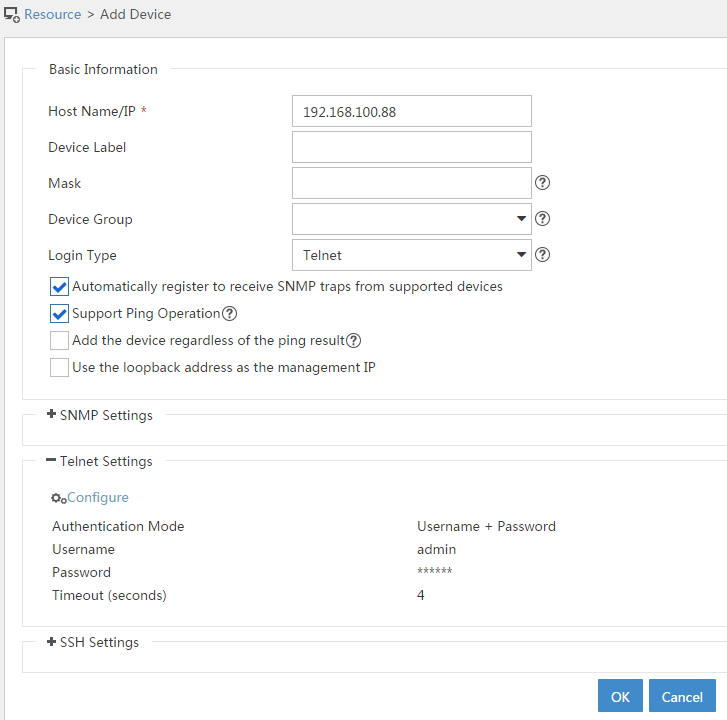
# Click OK.
3. Modify NETCONF settings:
# Click the Resource tab.
# From the navigation pane, select View Management > Device View.
# Click the link in the firewall Label column for the target device.
Figure 124 Device list

# In the right pane, click Configure > Modify NETCONF Settings.
# In the dialog box that opens, click the plus sign (+) to add a protocol as shown in Figure 125.
This example sets both the username and password to admin.
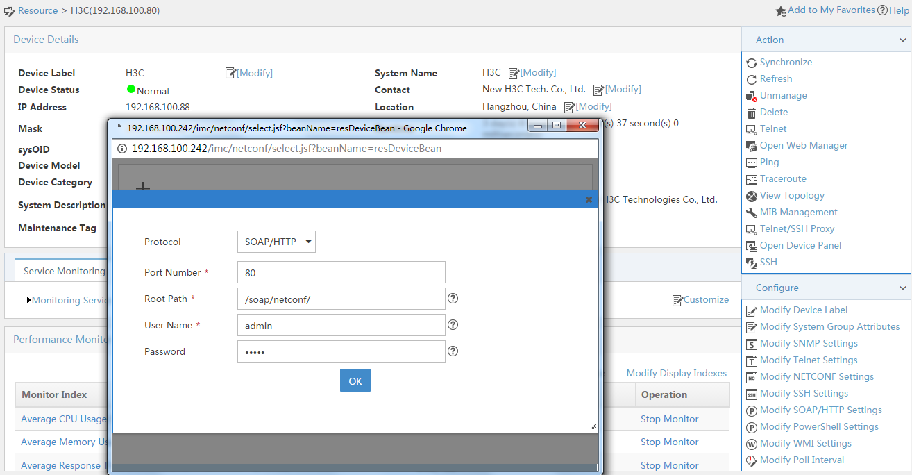
# Click OK.
Configuring security services on IMC
1. Synchronize security services from the firewall to the IMC server to ensure that the configuration and user information is consistent on the firewall and IMC server:
# Click the Service tab.
# From the navigation pane, select Security Service Manager > Device Management.
# On the Devices tab, view the firewall displayed in the device list.
Figure 125 Device management page (1)

# Select the firewall, click Synchronize, and then view the synchronization status in the Sync Status column.
The synchronization process might take a long time. Please wait.
Figure 126 Device management page (2)

Figure 127 Device management page (3)
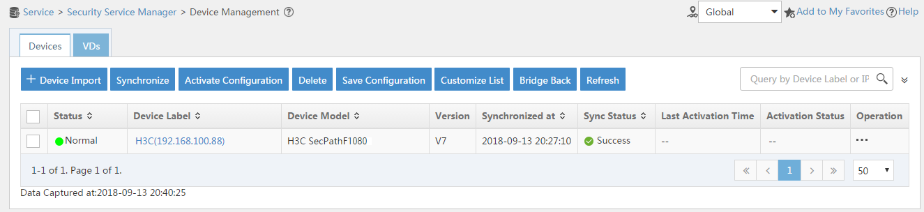
2. Configure user authentication system parameters and user notification parameters to ensure that the IMC server synchronizes user online and offline information to the firewall in real time:
# Click the Service tab.
# From the navigation pane, select Security Service Manager > Global Parameters.
# Configure the user authentication system parameters, and then click OK.
¡ Select a protocol based on the protocol type of the portal authentication server.
¡ The username and password must be the same as those configured on the firewall for logging in to the IMC server.
Figure 128 Configuring user authentication system parameters

# Click the User tab.
# From the navigation pane, select User Access Policy > Service Parameters > System Settings.
# Click the Configure icon for User Notification Parameters.
# Click Add.
# On the page that opens, configure the parameters as needed, and then click OK.
Because no shared key is used in this example, you can enter a shared key randomly.
Figure 129 Configuring user notification parameters
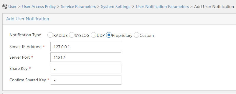
Configuring the RADIUS server on IMC
1. Enter the URL of IMC in the address bar of a browser to log in to IMC.
In this example, the URL for IMC is http://192.168.100.244:8080/imc/. The username and password are both admin. (Details not shown.)
2. Add the firewall to IMC as an access device:
# Click the User tab.
# From the navigation pane, select User Access Policy > Access Device Management > Access Device.
# Click Add.
# Set the shared key to admin and configure other parameters as shown in Figure 130.
Figure 130 Adding an access device

# Click OK.
|
|
NOTE: The IP address of the access device specified on IMC must be the source IP address of outgoing RADIUS packets specified on the firewall. By default, if no source IP address is specified for outgoing RADIUS packets, the IP address of the packet outgoing interface is used. · If you have executed the nas-ip or radius nas-ip command on the firewall to specify a source IP address for outgoing RADIUS packets, you must configure the specified address as the IP address of the access device. · In this example, the IP address 192.168.100.90 of the packet outgoing interface is used as the IP address of the access device. |
3. Add an access policy:
# Click the User tab.
# From the navigation pane, select User Access Policy > Access Policy.
# Click Add.
# Set the access policy name to Portal, and use the default settings for other parameters.
Figure 131 Adding an access policy

# Click OK.
4. Add an access service:
# Click the User tab.
# From the navigation pane, select User Access Policy > Access Service.
# Click Add.
# On the page that opens, configure the following parameters:
¡ Specify the service name as Portal.
¡ Select Portal from the Default Access Policy list.
Figure 132 Adding an access service
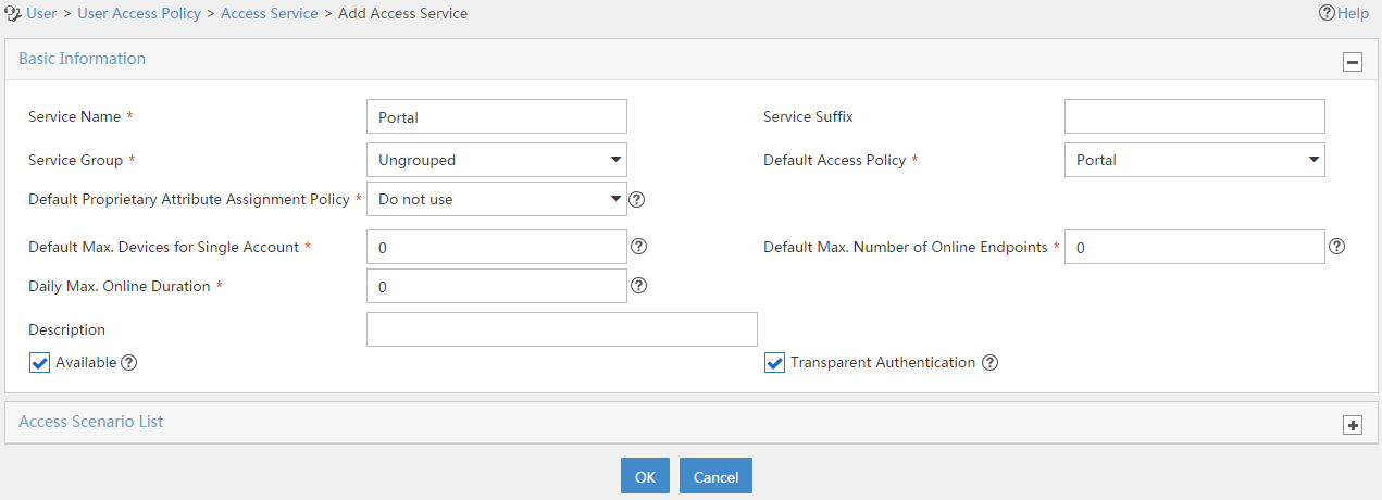
# Click OK.
5. Add an access user:
# Click the User tab.
# From the navigation pane, select Access User > All Access Users.
# Click Add.
# On the page that opens, configure the following parameters:
¡ Enter user in the User Name field.
¡ Enter user10001 in the Account Name field.
¡ Enter admin in the Password and Confirm Password fields.
¡ Select Portal in the Access Service area.
Figure 133 Adding an access user

# Click OK.
# Add user accounts user10002 and user10003 in the same way.
Configuring the portal server on IMC
1. Enter the URL of IMC in the address bar of a browser to log in to IMC.
In this example, the URL for IMC is http://192.168.100.244:8080/imc/. The username and password are both admin. (Details not shown.)
2. Configure the portal server:
# Click the User tab.
# From the navigation pane, select User Access Policy > Portal Service > Server.
# Configure the portal server parameters as needed. This example uses the default settings.
Figure 134 Configuring the portal server
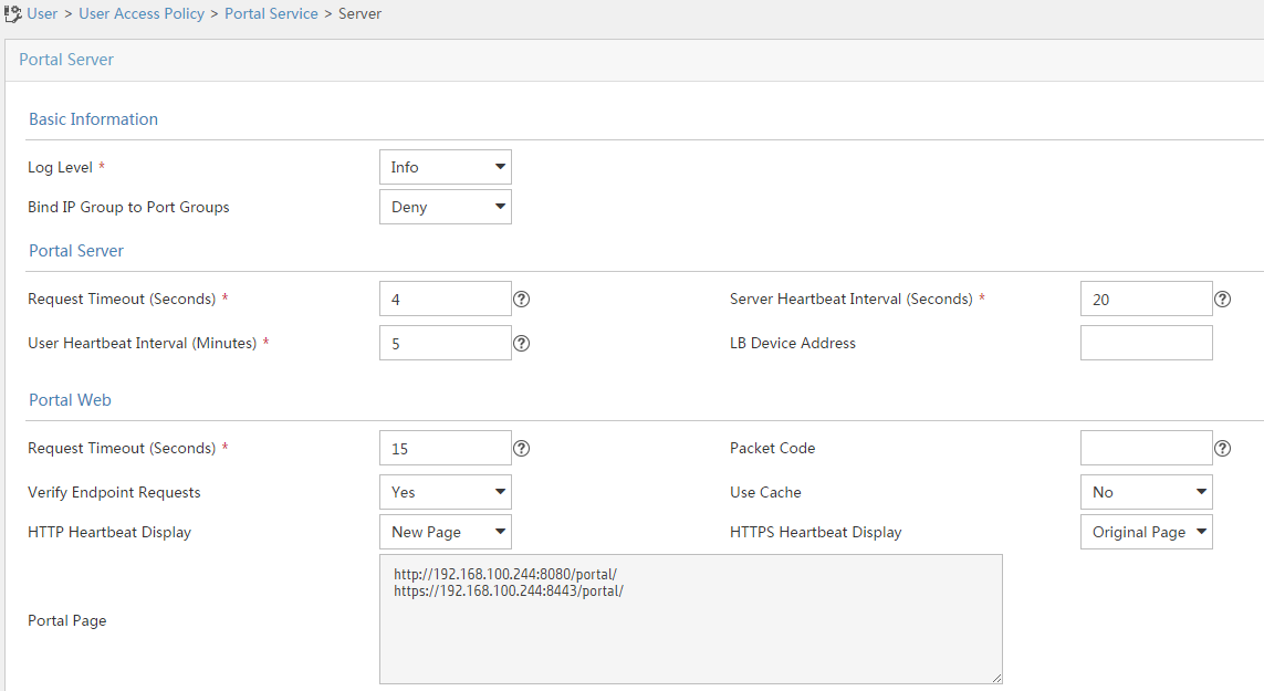
3. Add an IP group:
# Click the User tab.
# From the navigation pane, select User Access Policy > Portal Service > IP Group.
# Click Add.
# Configure the parameters as needed.
Figure 135 Adding an IP group

# Click OK.
4. Add a portal device:
# Click the User tab.
# From the navigation pane, select User Access Policy > Portal Service > Device.
# Click Add.
# Set the shared key to admin and configure other parameters as shown in Figure 136.
Figure 136 Adding a portal device
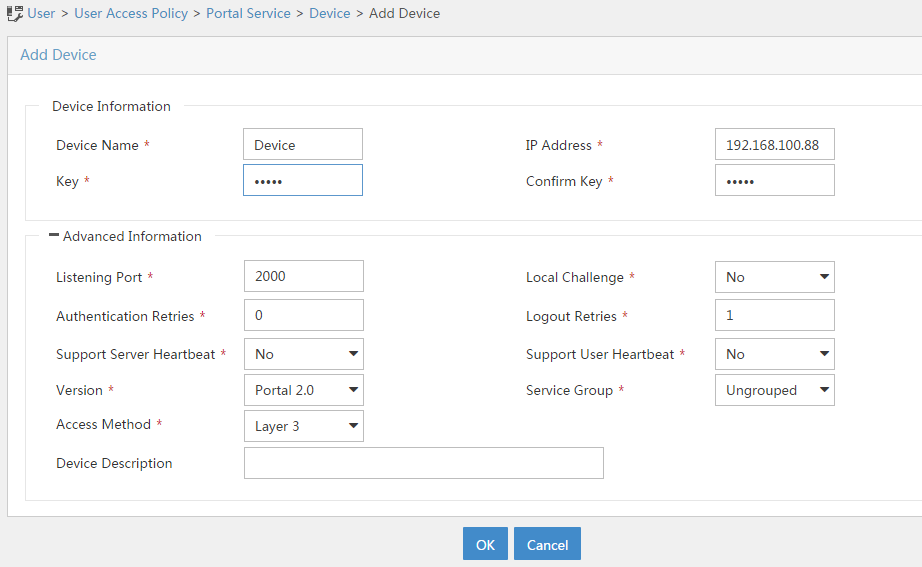
# Click OK.
5. Associate the portal device with the IP group:
# Click the User tab.
# From the navigation pane, select User Access Policy > Portal Service > Device.
# Click the Port Group icon in the Operation column for the firewall.
Figure 137 Device list
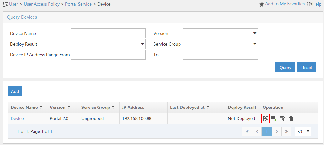
# Click Add.
# Configure the parameters as needed.
Figure 138 Adding a port group

# Click OK.
Configuring the hosts
Configure the IP address, subnet mask, and default gateway settings on each host. Make sure the hosts can communicate with other devices on the network. (Details not shown.)
Verifying the configuration
1. On the hosts, verify that the users can pass portal authentication:
# Enter the URL of the portal Web server in the address bar of a browser.
In this example, the URL is http://192.168.100.244:8080/portal.
# Enter the username and password.
# Click Log In.
# Verify that the user has passed portal authentication.
Figure 139 Portal authentication success page

2. On the IMC server, verify that you can view users user10001, user10002, and user10003 on the online user list of the User > Access User > Online Users page.
3. On the firewall, view information about all online portal users.
[Device] display portal user all
Total portal users: 3
Username: user10001
Portal server: newpt
State: Online
VPN instance: N/A
MAC IP VLAN Interface
0011-95e4-4aa9 20.2.1.13 -- GigabitEthernet1/0/2
Authorization information:
DHCP IP pool: N/A
User profile: N/A
Session group profile: N/A
ACL number: N/A
Inbound CAR: N/A
Outbound CAR: N/A
Username: user10002
Portal server: newpt
State: Online
VPN instance: N/A
MAC IP VLAN Interface
0011-95e4-4aa3 20.2.1.13 -- GigabitEthernet1/0/2
Authorization information:
DHCP IP pool: N/A
User profile: N/A
Session group profile: N/A
ACL number: N/A
Inbound CAR: N/A
Outbound CAR: N/A
Username: user10003
Portal server: newpt
State: Online
VPN instance: N/A
MAC IP VLAN Interface
0011-95e4-4aa2 20.2.1.13 -- GigabitEthernet1/0/2
Authorization information:
DHCP IP pool: N/A
User profile: N/A
Session group profile: N/A
ACL number: N/A
Inbound CAR: N/A
Outbound CAR: N/A
4. On the firewall, view identity user information:
# View information about all identity users.
[Device] display user-identity all user
User ID Username
0x2 user10001
0x3 user10002
0x4 user10003
# View information about online identity user user10001.
[Device] display user-identity online-user null-domain name user10001
User name: user10001
IP : 20.2.1.11
MAC : 0011-95e4-4aa9
Type: Dynamic
Total 1 records matched.
# View information about online identity user user10002.
[Device] display user-identity online-user null-domain name user10002
User name: user10002
IP : 20.2.1.12
MAC : 0011-95e4-4aa3
Type: Dynamic
Total 1 records matched.
# View information about online identity user user10003.
[Device] display user-identity online-user null-domain name user10003
User name: user10003
IP : 20.2.1.13
MAC : 0011-95e4-4aa2
Type: Dynamic
Total 1 records matched.
5. Verify that the firewall can perform identity-based access control on the users:
# Verify that user user10001 cannot ping hosts on the Internet. In this example, the user pings the host at 12.1.1.2.
C:\>ping 12.1.1.2
Pinging 12.1.1.2 with 32 bytes of data:
Request time out.
Request time out.
Request time out.
Request time out.
Ping statistics for 12.1.1.2:
Packets: Sent = 4, Received = 0, Lost = 4 (100% loss),
# Verify that user user10003 can ping hosts in the Internet. In this example, the user pings the host at 12.1.1.2.
C:\>ping 12.1.1.2
Pinging 12.1.1.2 with 32 bytes of data:
Reply from 12.1.1.2: bytes=32 time=36ms TTL=253
Reply from 12.1.1.2: bytes=32 time<1ms TTL=253
Reply from 12.1.1.2: bytes=32 time<1ms TTL=253
Reply from 12.1.1.2: bytes=32 time<1ms TTL=253
Ping statistics for 12.1.1.2:
Packets: Sent = 4, Received = 4, Lost = 0 (0% loss),
Approximate round trip times in milli-seconds:
Minimum = 0ms, Maximum = 36ms, Average = 9ms
# When user user10003 pings the host on the Internet, verify that the firewall generates a log as follows.
[Device]%Nov 6 10:19:53:920 2017 H3C FILTER/6/FILTER_ZONE_EXECUTION_ICMP: -Context
=1; SrcZoneName(1025)=Trust;DstZoneName(1035)=Untrust;Type(1067)=ACL;SecurityPolicy(
1072)=user10003;RuleID(1078)=3;Protocol(1001)=ICMP;SrcIPAddr(1003)=20.2.1.13;Src
MacAddr(1021)=7425-8a37-b5f6;DstIPAddr(1007)=12.1.1.2;IcmpType(1062)=ECHO(8);Icm
pCode(1063)=0;MatchCount(1069)=1;Event(1048)=Permit;
Configuration files
Router
[Router] display current-configuration
#
interface GigabitEthernet0/0
port link-mode route
ip address 20.2.1.1 255.255.255.0
#
interface GigabitEthernet0/1
port link-mode route
ip address 20.2.2.1 255.255.255.0
#
interface GigabitEthernet3/0
port link-mode route
combo enable copper
#
ip route-static 0.0.0.0 0 20.2.2.2
#
snmp-agent
snmp-agent local-engineid 800063A28074258A37B5F500000001
snmp-agent community write private
snmp-agent community read public
snmp-agent sys-info version all
#
local-user admin class manage
password hash $h$6$UbIhNnPevyKUwfpm$LqR3+yg1IjNct39MkOR0H0iQXLkYB3jMqM4vbAeoXOh
babIIFnjJPEGR00YiYA1Sz4LiY3FmEdru2fOLMb1shQ==
service-type telnet http
authorization-attribute user-role network-admin
#
return
Device
[Device] display current-configuration
#
interface GigabitEthernet1/0/1
port link-mode route
ip address 192.168.100.88 255.255.255.0
#
interface GigabitEthernet1/0/2
port link-mode route
ip address 20.2.2.2 255.255.255.0
portal enable method direct
portal domain dm1
portal apply web-server newpt
#
interface GigabitEthernet1/0/3
port link-mode route
ip address 12.1.1.1 255.255.255.0
#
security-zone name Trust
import interface GigabitEthernet1/0/2
#
security-zone name DMZ
import interface GigabitEthernet1/0/1
#
security-zone name Untrust
import interface GigabitEthernet1/0/3
#
line vty 0 63
authentication-mode scheme
user-role network-admin
#
ip route-static 0.0.0.0 0 12.1.1.2
ip route-static 20.2.1.0 24 20.2.2.1
#
snmp-agent
snmp-agent local-engineid 800063A280487ADA9593B700000001
snmp-agent community write private
snmp-agent community read public
snmp-agent sys-info version all
snmp-agent target-host trap address udp-domain 192.168.100.244 params securityn
ame public v2c
#
radius scheme rs1
primary authentication 192.168.100.244
primary accounting 192.168.100.244
key authentication cipher $c$3$hhbEbD5Ycvw7VWqljAoMoU7hQRgcUjtg
user-name-format without-domain
#
domain dm1
authentication portal radius-scheme rs1
authorization portal radius-scheme rs1
accounting portal radius-scheme rs1
#
domain system
#
domain default enable system
#
local-user admin class manage
password hash $h$6$UbIhNnPevyKUwfpm$LqR3+yg1IjNct39MkOR0H0iQXLkYB3jMqM4vbAeoXOh
babIIFnjJPEGR00YiYA1Sz4LiY3FmEdru2fOLMb1shQ==
service-type ssh telnet terminal http https
authorization-attribute user-role level-3
authorization-attribute user-role network-admin
authorization-attribute user-role network-operator
#
portal web-server newpt
url http://192.168.100.244:8080/portal
#
portal server newpt
ip 192.168.100.244 key cipher $c$3$+UmaGOco7eHsjOqlrp8lI4eYe0A8NpYU
#
netconf soap http enable
netconf soap https enable
restful http enable
restful https enable
#
user-identity enable
user-identity user-account auto-import policy imc
#
user-identity restful-server rest1
login-name admin password cipher $c$3$phGy00HA6OP6pIpGI0KOKZEOPuLVbtt/
uri get-user-database http://192.168.100.244:8080/imcrs/ssm/imcuser/accessUser
uri get-user-group-database http://192.168.100.244:8080/imcrs/ssm/imcuser/acces
sUserGroup
uri get-online-user http://192.168.100.244:8080/imcrs/ssm/imcuser/onlineUser
uri put-online-user http://192.168.100.244:8080/imcrs/ssm/imcuser/uploadOnlineU
ser
uri put-offline-user http://192.168.100.244:8080/imcrs/ssm/imcuser/uploadOfflin
eUser
#
user-identity user-import-policy imc
account-update-interval 1
restful-server rest1
#
security-policy ip
rule 0 name dmz-local
action pass
source-zone dmz
destination-zone local
rule 1 name local-dmz
action pass
source-zone local
destination-zone dmz
rule 2 name trust-dmz
action pass
source-zone trust
source-zone dmz
destination-zone dmz
destination-zone trust
rule 3 name user10003
action pass
logging enable
source-zone trust
destination-zone untrust
user user10003
#
return
