H3C SecPath Series Intrusion Prevention Products Security Device Bypass Configuration Examples (V7)-6W100-book.pdf(842.09 KB)
- Released At: 29-12-2022
- Page Views:
- Downloads:
- Table of Contents
- Related Documents
-
|
|
|
H3C SecPath Series Intrusion Prevention Products |
|
Security Service Bypass Configuration Examples |
|
|
|
|
Copyright © 2022 New H3C Technologies Co., Ltd. All rights reserved.
No part of this manual may be reproduced or transmitted in any form or by any means without prior written consent of New H3C Technologies Co., Ltd.
Except for the trademarks of New H3C Technologies Co., Ltd., any trademarks that may be mentioned in this document are the property of their respective owners.
The information in this document is subject to change without notice.
Contents
External bypass configuration examples
Example: Configuring dynamic external bypass
Example: Configuring static external bypass
Example: Configuring internal bypass
Example: Configuring internal bypass
Introduction
The following information provides configuration examples about the security device bypass feature.
Prerequisites
Procedures and information in the examples might be slightly different depending on the software or hardware version of the devices.
The configuration examples were created and verified in a lab environment, and all the devices were started with the factory default configuration. When you are working on a live network, make sure you understand the potential impact of every command on your network.
The following information is provided based on the assumption that you have basic knowledge of the security device bypass feature.
About security service bypass
Security service bypass can be classified into external bypass, internal bypass, and DPI bypass.
· External bypass—User traffic is forwarded by the Power Free Connector (PFC) device directly without passing through the security device. For more information about PFC devices, see H3C SecPath PFC Quick Start.
External bypass can be further classified into the following types:
¡ Dynamic external bypass—External bypass is enabled or disabled automatically based on the status of the links between the security device and the PFC device. The security device polls the link status periodically and enables external bypass if one or both links go down. External bypass is disabled automatically if the failed links come up.
The security device provides intrusion prevention functions and protects enterprise internal users from Internet attacks. To ensure that user traffic is under intrusion protection when the device works normally and is not affected when hardware exceptions occurred on the device deployed in standalone mode, enable dynamic external bypass on the device. In this way, if device power-off, reboot, or port down occurs, user traffic can be forwarded directly by the PFC device.
¡ Static external bypass—External bypass takes effect immediately when configured and must be manually disabled.
The security device provides intrusion prevention functions and protects enterprise internal users from Internet attacks. To manually upgrade or reboot the device, perform operations that might affect the traffic, or troubleshoot issues such as network traffic exception on the device, enable static external bypass on the device. In this way, the traffic is forwarded by the PFC device directly without passing through the security device. When the device environment recovers, manually disable static external bypass so that the traffic is under intrusion protection again.
· Internal bypass—User traffic is sent to the security device but is not processed by it. The security device directly forwards or drops the traffic according to the configured forwarding mode.
The security device provides intrusion prevention functions and protects enterprise internal users from Internet attacks. When the security device causes traffic exceptions such as traffic blocking or traffic stuck, enable internal bypass on the device to facilitate troubleshooting.
· DPI bypass—DPI bypass disables deep packet inspection for packets. Packet inspection in the DPI engine is a complex and resource-consuming process. You can enable DPI bypass in scenarios where packet inspection is not needed or must be ignored. For example, you can enable DPI bypass to guarantee the device performance when the CPU usage of the device is too high.
External bypass configuration examples
Example: Configuring dynamic external bypass
Network configuration
As shown in Figure 1, the security device is deployed in standalone mode to provide intrusion prevention functions and protect enterprise internal users from Internet attacks. Enable dynamic external bypass on the device to implement the following:
· When the device works normally, user traffic is under intrusion protection.
· When a hardware exception (power-off, reboot, or port down) occurs on the device, user traffic can be forwarded directly by the PFC device.
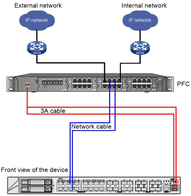
The device is connected to the PFC device as shown in Figure 2.

Figure 2 Device wiring diagram

Software versions used
The configuration examples were created and verified on Release R8860 of the T1000-AI-90 security device.
Restrictions and guidelines
When you configure dynamic external bypass, follow these restrictions and guidelines:
· Only a Layer 2 or Layer 3 Ethernet interface or a Layer 2 aggregate interface can be added to an interface pair operating in forward-type forwarding mode.
· Support for the dynamic external bypass feature depends on the device model.
Procedures
Configuring an interface pair and enabling dynamic external bypass
# Select Network > Interface Configuration > Inline > Interface Pairs.
# Click Create.
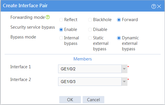
# Configure the interface pair as follows:
· Specify the forwarding mode as Forward.
· Enable security service bypass.
· Specify the bypass mode as Dynamic external bypass.
· Select GE1/0/2 and GE1/0/3 in the Interface 1 and Interface 2 fields, respectively.
Figure 3 Configuring the interface pair
Verifying the configuration
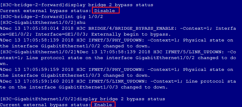
# Verify the following items:
· When a link goes down between the security device and the PFC device, traffic from Host A is forwarded to Host B directly by the PFC device.
· When the links between the security device and the PFC are operating correctly, the security device automatically disables external bypass and traffic from Host A is forwarded to Host B by the security device.
Figure 4 Dynamic external bypass
Configuration files
#
bridge 1 forward
bypass enable external auto
add interface GigabitEthernet1/0/2
add interface GigabitEthernet1/0/3
#
Example: Configuring static external bypass
Network configuration
As shown in Figure 5, the security device is deployed in standalone mode to provide intrusion prevention functions and protect enterprise internal users from Internet attacks. Enable or disable static external bypass on the device to implement the following:
· When you want to manually upgrade or reboot the device, perform operations that might affect the traffic, or troubleshoot issues such as network traffic exception on the device, enable static external bypass on the device. In this way, the traffic is forwarded by the PFC device directly without passing through the security device.
· When the device environment recovers, manually disable static external bypass so that the traffic is under intrusion protection again.
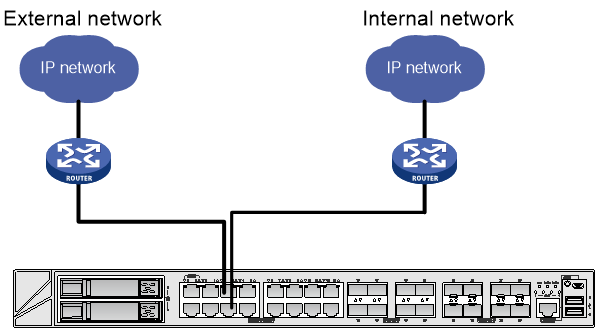
The device is connected to the PFC device as shown in Figure 6.
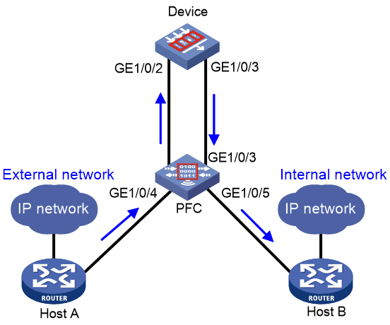
Figure 6 Device wiring diagram
Software versions used
The configuration examples were created and verified on Release R8860 of the T1000-AI-90 security device.
Restrictions and guidelines
When you configure static external bypass, follow these restrictions and guidelines:
· Only a Layer 2 or Layer 3 Ethernet interface or a Layer 2 aggregate interface can be added to an interface pair operating in forward-type forwarding mode.
· Support for the static external bypass feature depends on the device model.
Procedures
Configuring an interface pair and enabling static external bypass
# Select Network > Interface Configuration > Inline > Interface Pairs.
# Click Create.
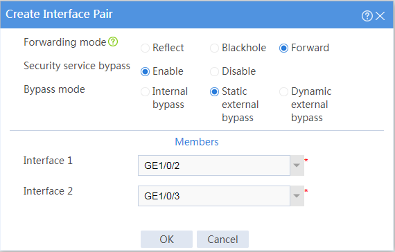
# Configure the interface pair as follows:
· Specify the forwarding mode as Forward.
· Enable security service bypass.
· Specify the bypass mode as Static external bypass.
· Select GE1/0/2 and GE1/0/3 in the Interface 1 and Interface 2 fields, respectively.
Figure 7 Configuring the interface pair
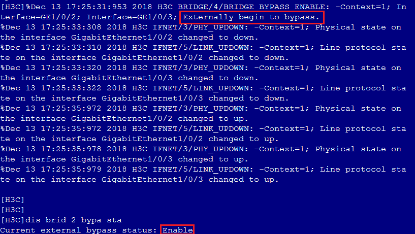
Verifying the configuration
# Verify that after static external bypass is enabled, the bridge forwarding interfaces flap and the traffic from Host A is forwarded to Host B directly by the PFC device without passing through the security device.
Figure 8 Static external bypass
Configuration files
#
bridge 1 forward
bypass enable external
add interface GigabitEthernet1/0/2
add interface GigabitEthernet1/0/3
#
Example: Configuring internal bypass
Network configuration
As shown in Figure 9, the security device is deployed in standalone mode to provide intrusion prevention functions and protect enterprise internal users from Internet attacks. Enable internal bypass on the device to facilitate troubleshooting when the security device causes traffic exceptions such as traffic blocking or traffic stuck. In this way, user traffic is sent to the security device but is not processed by it. The security device directly forwards or drops the traffic according to the configured forwarding mode.
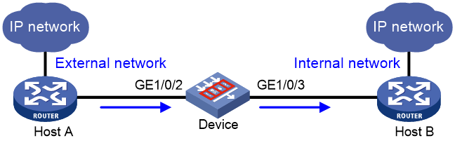
Figure 10 Device wiring diagram
Software versions used
The configuration examples were created and verified on Release R8860 of the T1000-AI-90 security device.
Restrictions and guidelines
When you configure internal bypass, follow these restrictions and guidelines:
· Only a Layer 2 Ethernet interface or aggregate interface can be added to an interface pair operating in forward-type forwarding mode.
· Support for the internal bypass feature depends on the device model.
Procedures
Configuring an interface pair and enabling internal bypass
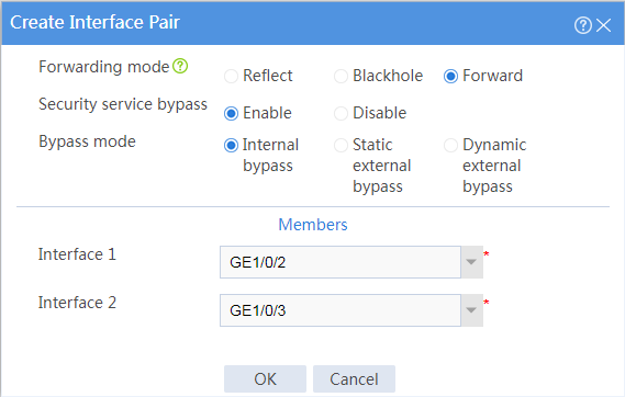
# Select Network > Interface Configuration > Inline > Interface Pairs.
# Click Create.
# Configure the interface pair as follows:
· Specify the forwarding mode as Forward.
· Enable security service bypass.
· Specify the bypass mode as Internal bypass.
· Select GE1/0/2 and GE1/0/3 in the Interface 1 and Interface 2 fields, respectively.
Figure 11 Configuring the interface pair
Verifying the configuration
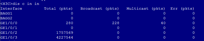
# Verify that traffic from Host A to Host B is sent to the security device but is not processed by it.
Figure 12 Internal bypass
Configuration files
#
bridge 1 forward
bypass enable
add interface GigabitEthernet1/0/2
add interface GigabitEthernet1/0/3
#
Example: Configuring internal bypass
Network configuration
As shown in Figure 13, a security device is deployed to provide security processing for traffic from Host A to Host B. To guarantee the device performance when the CPU usage of the device is too high, you can enable DPI bypass on the device. With DPI bypass enabled, traffic from Host A to Host B is not processed by the DPI engine.

Software versions used
The configuration examples were created and verified on Release R8860 of the T1000-AI-90 security device.
Restrictions and guidelines
When you configure DPI bypass, follow these restrictions and guidelines:
· The bypass feature disables the DPI engine so packets will not be processed by DPI. Before enabling DPI bypass, make sure DPI process is not needed on the device.
· Support for the DPI bypass feature depends on the device model.
Procedures
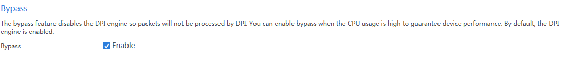
Enabling DPI bypass to disable the DPI engine
# Select Objects > APP Security > Advanced Settings.
# Select Enable next to Bypass.
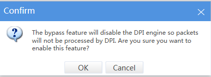
# In the confirmation dialog box that opens, click OK.
Figure 14 Enabling DPI bypass
Verifying the configuration
# Verify that traffic from Host A to Host B is not processed by the DPI engine when DPI bypass is enabled.
Figure 15 DPI bypass

Configuration files
#
Inspect bypass
#
