| Title | Size | Downloads |
|---|---|---|
| iNOF Technology White Paper-6W100-book.pdf | 645.96 KB |
- Table of Contents
- Related Documents
-
| Title | Size | Download |
|---|---|---|
| book | 645.96 KB |
iNOF Technology White Paper
Copyright © 2024 New H3C Technologies Co., Ltd. All rights reserved.
No part of this manual may be reproduced or transmitted in any form or by any means without prior written consent of New H3C Technologies Co., Ltd.
Except for the trademarks of New H3C Technologies Co., Ltd., any trademarks that may be mentioned in this document are the property of their respective owners.
The content in this article is of a general technical nature, some of which may not be applicable to the product you have purchased.
Contents
Network element in an NFV environment
Extended LLDP advertisement message
Differences in iNOF-related messages between iNOF protocols
iNOF direct-connected networking
BFD-based link failure detection
BFD notifies iNOF of link failures
Technical features implemented by H3C
iNOF networking without reflectors deployed
iNOF networking with reflectors deployed
Overview
Background
As the global acceleration of enterprise digital transformation continues, and internet applications increasingly penetrate into the fields of production and daily life, storage networks are growing in scale, requiring the processing of ever-greater amounts of data. Data center deployments at headquarters and branch offices are situated in different physical locations, making RDMA (Remote Direct Memory Access) a mainstream technology for storage networks. RDMA leverages related hardware and network technologies to enable direct memory reads between network cards of hosts, ultimately achieving high bandwidth, low latency, and low resource consumption rates. However, RDMA was initially designed to operate over lossless IB (InfiniBand) networks, which are dedicated, closed architectures that are not compatible with existing networks and come with high usage costs. Consequently, RoCE (RDMA over Converged Ethernet) was developed.
RoCE is a network protocol that carries RDMA over Ethernet, and it comes in two versions: RoCEv1 is a link layer protocol that cannot be used across different broadcast domains; RoCEv2 is a network layer protocol that can implement routing functions.
Current applications such as high-performance computing, distributed storage, and artificial intelligence all use the RoCEv2 protocol to reduce CPU processing and latency, thereby enhancing application performance. The RoCEv2 protocol lacks a robust packet loss protection mechanism, but storage services are exceptionally sensitive to network packet loss. To unleash the true performance of RDMA in an Ethernet environment and break through the network performance bottleneck of large-scale distributed systems in data centers, we use intelligent lossless network technology to create a "no packet loss, low latency, high throughput" lossless network environment for RDMA.
Intelligent lossless networking is a collection of technologies that on one hand, enhance the overall network throughput and reduce latency through traffic control and congestion control techniques, and on the other hand, achieve network and application system integration and optimization through technologies such as intelligent lossless storage networking.
iNOLF (Intelligent Lossless NVMe Over Fabric) is a technology that optimizes the integration of Ethernet and storage networks. It enables the automatic discovery of massive storage devices, rapid perception of network faults, and promptly notifies all devices within the intelligent lossless network of the addition and removal of storage devices, providing foundational support for the realization of a "no packet loss, low latency, high throughput" intelligent lossless network.
Benefits
iNOF has the following basic benefits:
· Plug and play
The iNOF switch can discover a new host as soon as the host accesses the iNOF network. Then, it synchronizes this change to other switches on the network and other hosts in the iNOF zone to which the new host belongs. Hosts in the same zone will automatically establish connections with the new host to ensure fast storage service expansion.
· Fast network failure detection
The iNOF switch can detect network failures promptly and forward this event to other switches on the network and the hosts connected to that switch. Hosts disconnect from the storage devices affected by network failures and use redundant paths to ensure service continuity.
Implementation of iNOF
Network element in an NFV environment
An iNOF network includes the following elements:
· Host—iNOF-capable network servers and disk devices.
· Switch—iNOF-capable switches that provide network access to iNOF hosts.
· Zone—iNOF introduces the concept of zone to manage hosts. An iNOF zone has multiple hosts. When you add a new host into or remove a host from the zone, iNOF informs this event to other hosts in that zone. iNOF zones are divided into the following types:
¡ User-defined zone—A user-defined zone is created by users. Users must add hosts into the zone manually according to network requirements.
¡ Default zone—By default, an iNOF switch has a default iNOF zone that cannot be deleted. Users can select whether to enable automatic adding of free hosts to the default zone. A free host refers to a host that is not a member of any user-defined zones.
iNOF networking
Directly connected network
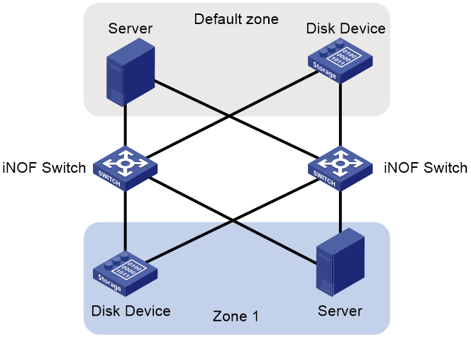
As shown in Figure 1, the hosts in an iNOF zone connect to the same iNOF switch. Each host exchanges Layer 2 packets with the switch to ensure they are aware of the state changes of connected hosts. Switches do not exchange iNOF information with each other. This iNOF network type is applicable to small networks.
Figure 1 Directly connected network
Cross-switch network
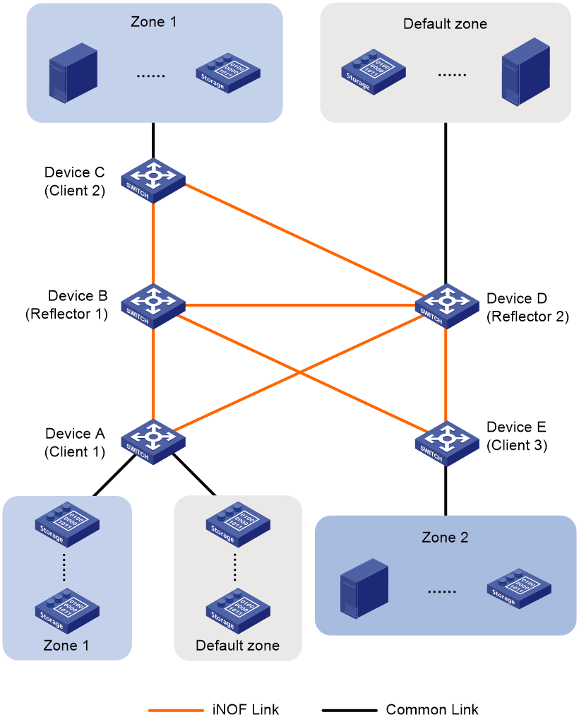
As shown in Figure 2, the hosts in the same iNOF zone can connect to different iNOF switches. These switches exchange dynamic host information. This iNOF network type is applicable to large-scale data centers with multiple hosts from different organizations or departments. The hosts in the same organization or department connect to different iNOF switches.
A cross-switch iNOF network is established as follows:
· Each host directly connects to an iNOF switch. They communicate with each other in the same way as they do on the directly connected iNOF network.
· The iNOF switches establish IBGP sessions to each other and exchange iNOF route information through BGP. iNOF switches can be connected by using either of the following methods:
¡ Full-mesh—Each iNOF switch establishes connections with the other iNOF switches. This method is tedious and is unfavorable for network expansion.
¡ Route reflection—H3C has extended BGP for iNOF adaption. In the cross-switch networking scenario, use the route reflection method as a best practice to simplify the network. Other switches can promptly receive the state changes of iNOF hosts connected to a switch. In BGP iNOF address family, iNOF switches exchange iNOF route information that includes dynamic iNOF host information and iNOF configuration information.
|
|
NOTE: · To simplify a cross-switch iNOF network, configure a minimum of one switch as the iNOF reflector and the rest of switches on that network as iNOF clients. All clients establish iNOF connection with the iNOF reflector and each host directly connects to an iNOF reflector or client. To avoid unexpected or unsolvable issues during frequent route changes, do not establish any iNOF connections between clients. · To improve network availability, you can specify multiple route reflectors for an iNOF zone. The failure of a reflector does not affect service continuity, because other reflectors still run normally. These route reflectors and their clients automatically form a cluster. The route reflectors in the cluster must have the same cluster ID to avoid routing loops. |
Messages used by iNOF
During the operation of iNOF, it uses the messages shown in Table 1.
|
Message name |
Transmitter (Tx) --> Receiver |
Packet description |
|
Extended LLDP advertisement message |
Host -> iNOF switch |
Informs the directly connected iNOF switch about the host's joining and changes in host parameters. |
|
iNOF state notification message |
iNOF switch --> host |
Notifies other hosts in the same domain about a host leaving the iNOF domain. |
|
iNOF state ACK message |
Host --> iNOF switch |
Acknowledges the received notification message. |
|
iNOF message |
iNOF switch --> iNOF switch |
Synchronizes configurations and inform the peer iNOF switch about local host status changes detected. |
Extended LLDP advertisement message
iNOF has extended the LLDP advertisement message, redefining certain fields within the LLDP message to implement the function of announcing host join evens. The redefinition of the LLDP advertisement message by iNOF is mainly reflected in the following aspects:
· The host identifier is carried through the ChassisID and PortID fields, with "ChassisID+PortID" uniquely identifying a host.
¡ Chassis ID: Represented by the MAC address of the port on the host that accesses the iNOF network (e.g., 0800-271a-494f).
¡ PortID: Represented in the format of prefix+port name. The prefix uses a fixed string. In the ODCC specification, the prefix is snsd. In the China Mobile specification, the prefix is roce-san_.
· Host iNOF parameters are carried by adding a new LLDP extension TLV.
Figure 3 LLDP extension TLV
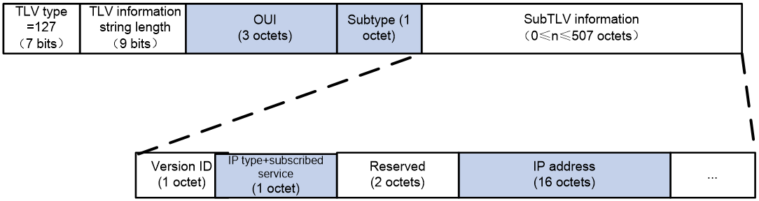
The iNOF extension TLV format is shown in the above figure, where iNOF primarily uses the following fields:
· OUI (Organizationally Unique Identifier): Indicates the iNOF specification followed by the host.
· Subtype: Indicates that the TLV is an iNOF extension TLV, carrying iNOF-related information.
· IP Type: A value of 1 indicates an IPv4 address and a value of 2 indicates an IPv6 address.
· Subscription Service: Indicates whether the host subscribes to network information change messages. This field shows whether the host wants to be aware of the joining and leaving status changes of other hosts in the same domain.
¡ A value of 1 indicates subscription, meaning the host needs to be notified when other hosts in the same domain join or leave the network.
¡ A value of 0 indicates no subscription, meaning there is no need to notify the host when other hosts in the same domain join or leave the network.
For servers, it is mandatory to subscribe to network information change messages. For disk devices, subscribing is optional.
· IP Address: IP address of the host. For IPv4 addresses, only the first 4 bytes are used, and the remaining bytes are filled with zeros.
Status notification messages
When a host's network status changes (e.g., joining, leaving, or access link failure), the iNOF switch directly connected to the host detects the change in network information and sends a status notification message to other hosts in the same domain that are directly connected. This allows other hosts to quickly become aware of the network status change so that they can promptly establish connections with the new host, disconnect from the leaving host, or quickly perform link switching.
There are two types of status notification messages:
· Notification message: Generated on the iNOF switch and sent to the host, used to notify the host of network information changes.
· ACK message: Generated on the host and sent to the iNOF switch, used to acknowledge the received notification message.
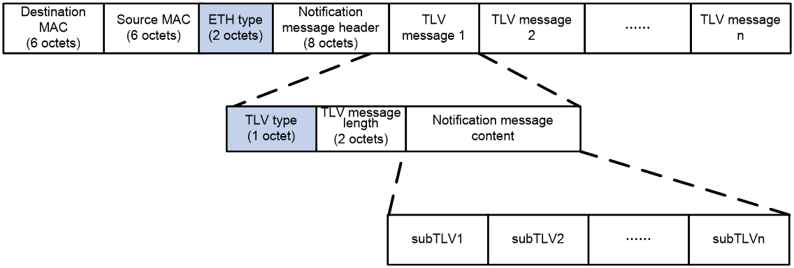
The format of the iNOF notification message is shown in Figure 3. For a description of the important fields in the message, please refer to Table 2. Devices determine whether a message is an iNOF notification message by the value of the ETH type field and then determine whether it is a notification message or an ACK message based on the value of the TLV type field.
Figure 4 iNOF status notification message
|
|
NOTE: In an iNOF notification message, multiple TLVs can be included. For H3C devices, an iNOF notification message can carry only one TLV. |
Table 2 Important fields in a status notification message
|
Field type |
Field name |
Field length |
Parameters |
|
ETH frame header |
Destination MAC address |
6 bytes |
The fixed value is 0180-C200-000D. |
|
Source MAC address |
6 bytes |
MAC address of the message sender. |
|
|
ETH type |
2 bytes |
· In the ODCC specification, the value of this field is set to 0x88A7. · In the China Mobile standards, the value of this field is set to 0x7777. |
|
|
Notification message header |
Version ID |
1 byte |
Version number, and its current value is 1. |
|
Reserved field |
1 byte |
Reserved field. |
|
|
Total length of the message |
2 bytes |
The notification message can carry multiple TLV messages; this field indicates the total length of all TLV messages, excluding the length of the ETH frame header and the notification message header. |
|
|
Reserved field |
4 bytes |
Reserved field. |
|
|
TLV message |
TLV type |
1 byte |
· In the ODCC standards, a value of 33 indicates that the message is a notification message. In the China Mobile standards, a value of 1 indicates that the message is a notification message. ¡ For IPv4 notification messages, the message content must carry subTLV of types 1, 2, 5, 6, 7, and 8. ¡ For IPv6 notification messages, the message content must carry subTLVs of type 3, 4, 5, 6, 7, and 8. · In the ODCC standard, a value of 34 signifies that the message is an ACK message. In the China Mobile standard, a value of 2 also signifies that the message is an ACK message. ¡ For IPv4 ACK messages, the message content must carry subTLVs of type 1, 2, and 5. ¡ For IPv6 ACK messages, the message content must carry subTLV of types 3, 4, and 5. The subTLV1 and subTLV2 carried in the ACK message must remain consistent with the original notification message, to be checked by the switch. |
|
TLV message length |
2 bytes |
Length of the notification message content, excluding TLV type and TLV message length. |
|
|
Notification message content. |
Variable length |
Different TLVs carry different combinations of subTLVs. See Table 3 for the definition of subTLVs. |
Table 3 SubTLV format
|
Sub-TLV type |
Sub-TLV message length |
Description |
|
1 |
4 bytes |
IPv4 address of the host where the network state has changed. The value should be an IPv4 address. |
|
2 |
4 bytes |
Destination IPv4 address, which is the IPv4 address of the host within the same domain that subscribed to the network information change message. The value is an IPv4 address. |
|
3 |
16 bytes |
IPv6 address of the host where the network state has changed. The value is an IPv6 address. |
|
4 |
16 bytes |
Destination IPv6 address, which is the IPv6 address of the host within the same domain that subscribed to the network information change message. The value is an IPv6 address. |
|
5 |
4 bytes |
Message serial number. The value is the message serial number, which increases by 1 for each message. The serial number carried in the ACK message must be the same as the serial number carried in the notification message it acknowledges. |
|
6 |
4 bytes |
State of the host. The value is: · 0: Offline. · 1: Online. |
|
7 |
4 bytes |
Reason code for device state change. The value is: · 0: Normal. · 1: The host is offline because the link between the host and the iNOF switch is disconnected. · 2: The host is offline because the iNOF switch detected a PFC deadlock on the interface connected to the host. · 3: The host is offline because the iNOF switch detected an access failure to the iNOF switch or a cascading link failure between iNOF switches through BFD. · 4: The host is offline because of domain configuration changes, and the host has been removed from the domain. · 5: The host is offline because of changes in the host's IP address configuration. · 6: The host is offline because the host has not sent an LLDP advertisement message to the iNOF switch for more than 120 seconds. |
|
8 |
Variable Length |
Additional information related to the device. The value is filled by the host manufacturer. |
iNOF messages
BGP has added a new BGP iNOF address family for iNOF and carries iNOF routing information, through the MP_REACH_NLRI (Multiprotocol Reachable NLRI) or MP_UNREACH_NLRI (Multiprotocol Unreachable NLRI) fields in BGP Update messages. iNOF routing information is conveyed via the MP_REACH_NLRI field in BGP Update messages. Within the BGP iNOF address family, devices can exchange iNOF routing information, which is used to transmit messages about the joining or leaving of hosts, as well as iNOF's configuration information.
BGP Update
As shown in Figure 2, a BGP iNOF message has the Type field in the BGP Header area with a value of 2, indicating that the message is a BGP Update message. The Unfeasible routes length field of the BGP iNOF message has a fixed value of 0, with iNOF routing information encapsulated in the Path Attributes field.
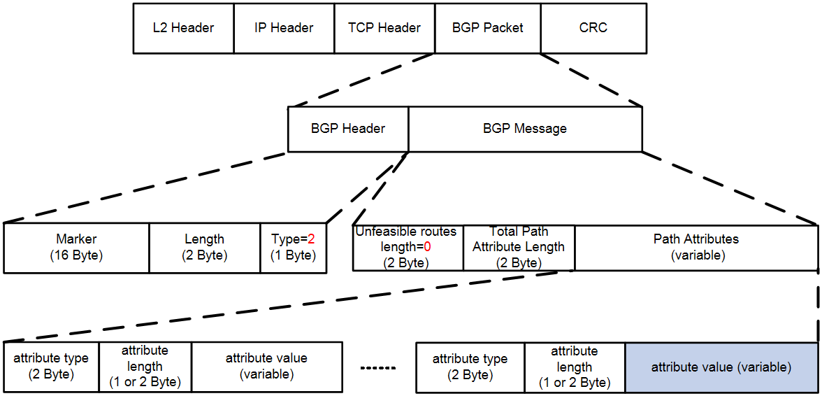
Path Attributes
Path Attributes is a variable-length field; it is a list that can contain multiple triplets (attribute type, attribute length, and attribute value) to convey different types of BGP attributes.
Attribute type indicates the type of BGP attribute, occupying 2 bytes, consisting of Attr.Flags (attribute flags) and Attr.Type.
· Attr.Type Code=14, indicating MP_REACH_NLRI.
If an iNOF host joins the iNOF network, its information changes, or there is an iNOF configuration change, the iNOF switch connected to the iNOF host will generate a BGP Update message with Attr.Type Code=14 to notify all directly connected iNOF switches. Since the reflector is directly connected to the iNOF switch, it also receives this BGP Update message and reflects it to all other iNOF switches.
· Attr.Type Code=15, indicating MP_UNREACH_NLRI.
If an iNOF host leaves the iNOF network, the reflector will generate a BGP Update message with Attr.Type Code=15 to notify all iNOF switches in the network.
· attribute length indicates the length of the BGP attribute, which may occupy 1 byte or 2 bytes.
¡ If the 4th bit in Attr.Flags (indicating Extended Length) has a value of 0, then attribute length occupies 1 byte.
¡ If the 4th bit in Attr.Flags has a value of 1, then attribute length occupies 2 bytes.
· Attribute value represents the value of the BGP attribute, which is a variable-length field.
This field can be used to advertise IPv6 BGP, FlowSpec, iNOF, and other routes. BGP uses the Address Family Identifier and Subsequent Address Family Identifier fields to distinguish different routes. When Address Family Identifier=6000 and Subsequent Address Family Identifier=254, it indicates BGP iNOF routing.
¡ When publishing or modifying BGP iNOF routing, the internal structure of its attribute value is as shown in Figure 3. iNOF information is encapsulated in the Network Layer Reachability Information field.
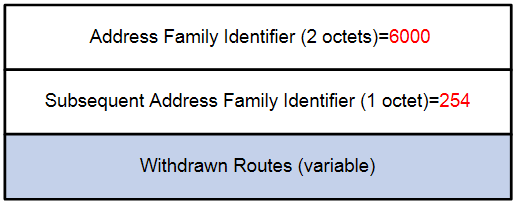
¡ When deleting BGP iNOF routing, the MP_UNREACH_NLRI field is used, and its attribute value internal structure is as shown in Figure 4. iNOF information is encapsulated in the Withdrawn Routes field.
The Network Layer Reachability Information field and the Withdrawn Routes field have the same structure, both using the <length, prefix> format, where prefix is the TLV structure encapsulated by the iNOF module, and length is the length of the prefix.
Figure 6 attribute value in MP_REACH_NLRI message
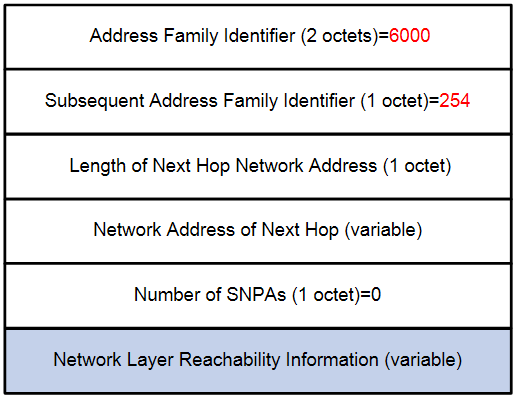
Figure 7 attribute value in MP_UNREACH_NLRI message
iNOF TLV structure
iNOF, based on its business needs, has defined five types of TLV structures. When corresponding events occur, iNOF assembles the relevant information into the corresponding TLV structure and sends it to the BGP module. The BGP module then encapsulates it into the Network Layer Reachability Information field's prefix area of the MP_REACH_NLRI message or the Withdrawn Routes field's prefix area of the MP_UNREACH_NLRI message. A single BGP Update message can include all five types of iNOF TLV structure types, and multiple pieces of information of the same iNOF TLV structure type can also be integrated and transmitted in a single BGP Update message. When a device receives the same iNOF message from different neighbors, it selects the best message and propagates it via a BGP Update message. A BGP Update message can also carry BGP iNOF routes and other BGP route attributes (such as IPv6 routes and Flowspec routes.) simultaneously to improve the efficiency of BGP route transmission and accelerate the convergence speed of BGP routes.
Table 4 iNOF TLV structure
|
ID |
Message TLV structure type |
Description |
Attr.Type Code value in the generated BGP message |
|
1 |
Host TLV |
Sent upon host adding |
14 |
|
Sent upon host deletion |
15 |
||
|
Sent upon host or storage information changes |
14 |
||
|
2 |
Zone TLV |
Sent upon zone adding |
14 |
|
Sent upon zone deletion |
15 |
||
|
3 |
ZoneHost TLV |
Sent upon adding host information to a zone |
14 |
|
Sent upon deleting host information from a zone |
15 |
||
|
4 |
DefaultZone TLV |
Sent when the function of automatic host adding to the default zone changes |
14 |
|
5 |
HardZone TLV |
Sent when the iNOF zone isolation function is configured |
14 |
By default, automatic adding of free hosts to the default iNOF zone is enabled. If the undo default-zone enable command is configured on the reflector to disable the iNOF default domain auto-join function, the iNOF module will generate a data block with the TLV structure as shown in Figure 5 and send it to the BGP module. The BGP module will then generate a BGP Update message with Attr.Type Code=14 and fill the DefaultZone TLV structure data block into the Path Attributes/attribute value/Network Layer Reachability Information field of the message, and then release the message to all BGP clients. When BGP clients receive and parse this message, they will disable the iNOF default domain auto-join function on the local machine.
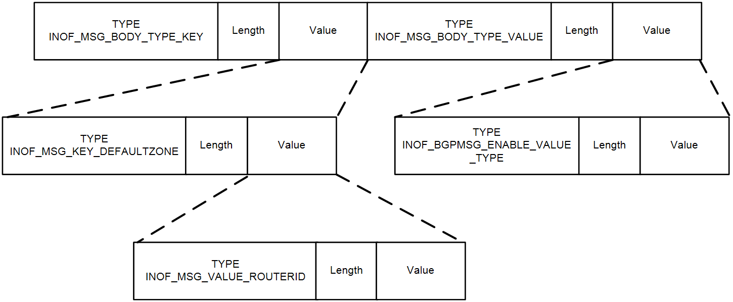
Table 5 DefaultZone TLV
|
Field name |
Field length (in bytes) |
Parameters |
|
INOF_MSG_BODY_TYPE_KEY |
2 |
TLV type, which has a value of 2. |
|
INOF_MSG_BODY_TYPE_VALUE |
2 |
TLV type, which its value is 3. |
|
INOF_MSG_KEY_DEFAULTZONE |
2 |
TLV type, which its value is 4. |
|
INOF_MSG_VALUE_ROUTERID |
4 |
Router ID of the router. |
|
INOF_BGPMSG_ENABLE_VALUE_TYPE |
4 |
Enabling status of the DefaultZone function. |
Differences in iNOF-related messages between iNOF protocols
Currently, the main iNOF protocols include ODCC-2020-05016: NVMe over RoCEv2 and China Mobile RoCE-SAN Solution v03 20210817. iNOF switches negotiate with hosts to decide which of these two protocols to use for message exchange.
The values of individual fields in iNOF messages vary by iNOF protocol. For details, see the following table:
Table 6 Differences in iNOF messages between different iNOF protocols.
|
Field in the iNOF message |
Value defined in the ODCC specification |
Value defined in China Mobile's specification |
|
OUI field in the LLDP announcement message |
0x001882 |
0x5C75C6 |
|
subtype field in the LLDP advertisement message. |
101 |
88 |
|
Port ID field in the LLDP announcement message. |
The value for the prefix segment in the Port ID field is: snsd_ |
The value for the prefix segment in the Port ID field is: roce-san_ |
|
ETH type field in the state notification message. |
0x88A7 |
0x7777 |
|
TLV type field in the state notification message. |
· 33: Notification messages. · 34: ACK (Acknowledgement) message. |
· 1: Notification message. · 2: ACK (Acknowledgement) message. |
iNOF operating Mechanism
iNOF direct-connected networking
Host joining
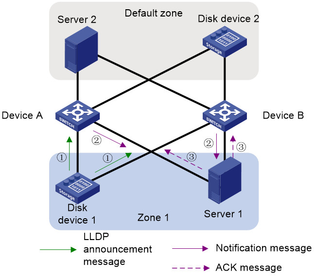
Both the host and the iNOF switch must support and enable the LLDP function. In the iNOF network shown in the following figure , Server 1 and Disk Device 1 belong to the same custom domain zone 1, and Server 2 and Disk Device 2 belong to the default domain. When a host (e.g., Disk Device 1) connects to an iNOF switch, the message exchange process between devices is as follows:
1. The host proactively sends LLDP advertisement messages to the directly connected iNOF switches (Device A and Device B), with the messages recording LLDP neighbor change information and requesting subscription to network information change messages.
2. Upon receiving the LLDP advertisement messages, the iNOF switches proceed as follows:
a. Maintain the local host information database.
The iNOF switch precisely searches the local host information database using "ChassisID+PortID" as the key.
- If a corresponding record is found, it is considered that the host has joined the iNOF network; the host information aging timer is updated, and other parameter values are compared for changes. If other parameter values have changed, the local corresponding record is updated; if there are no changes in other parameter values, no further action is needed. (iNOF switches use the host information aging timer to automatically maintain host records. For existing host records in the local host information database, if the host's LLDP advertisement message has not been received by the time the host information aging timer expires, the iNOF switch will consider the host to have gone offline and will take appropriate action. The duration of the host information aging timer is determined by the host, with the current value being 120 seconds.)
- If no corresponding record is found, it is considered that the host is new. The iNOF switch creates a record for the host in the host information database and starts the host information aging timer.
b. Send a notification message to inform about the change in network information.
- For new hosts that have joined and subscribed to network information change messages (Disk Device 1), the iNOF switch notifies the host of the status information of all devices in the domain (Server 1).
- For directly connected hosts that belong to the same iNOF domain and have subscribed to network information change messages (Server 1), the iNOF switch notifies them (Server 1) of the information of the newly joined host (Disk Device 1).
3. The host acknowledges the notification.
Server 1 sends ACK messages to Device A and Device B, indicating that it is aware of the new host joining. If the iNOF switch does not receive the ACK message from the host, it will resend the notification message.
Figure 9 Host joining
Host leaving
When the following situations occur, the iNOF switch will consider the host to have left and will initiate the host leave notification process:
· The link between the host and the iNOF switch is disconnected.
· The iNOF switch detects a PFC deadlock on the interface connected to the host.
· The iNOF switch detects an access switch failure or a cascading link failure between iNOF switches through BFD.
· Domain configuration changes, and the host is removed from the domain.
· The host's IP address configuration changes.
· The host has not sent an LLDP advertisement message to the iNOF switch for more than 120 seconds (the duration of the host information aging timer, currently set to 120 seconds).
When a host leaves, the message exchange process between devices is as follows:
1. The iNOF switch determines that the host has left and deletes the corresponding record from the local host information database. It notifies other directly connected hosts in the same iNOF domain and subscribed to network information change messages that a device has gone offline.
2. Server 1 sends ACK messages to Device A and Device B, indicating that it is aware of the host going offline. If the iNOF switch does not receive the ACK message from the host, it will resend the notification message.
iNOF cross-switch networking
Establish iNOF connections
iNOF leverages the BGP route reflection technology; iNOF connections reuse iBGP connections. Therefore, before deploying iNOF, it is necessary to complete the configuration of iBGP and reflectors on all iNOF switches.
After enabling the iNOF feature on an iNOF switch, the reflector will send BGP routes to clients and other reflectors, with iNOF information carried within as route attributes.
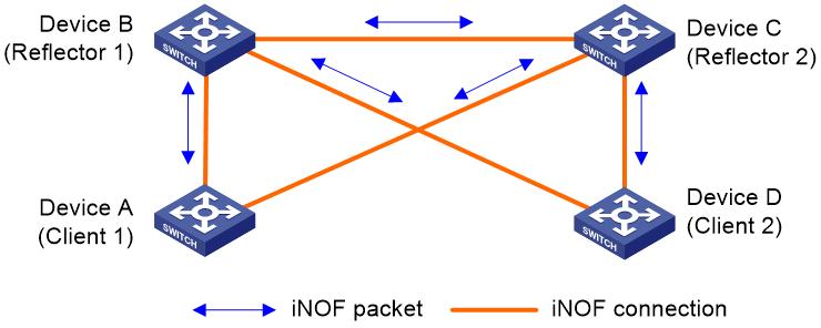
As shown in the following figure, assuming Device B and Device C are reflectors, and Device A and Device D are clients. Device B will establish iBGP connections with Device A, Device C, and Device D respectively; Device C will establish iBGP connections with Device A, Device B, and Device D respectively.
Figure 10 Establishing iNOF connections (reflectors deployed)
Host joining
Figure 11 Host joining in the multi-reflector scenario
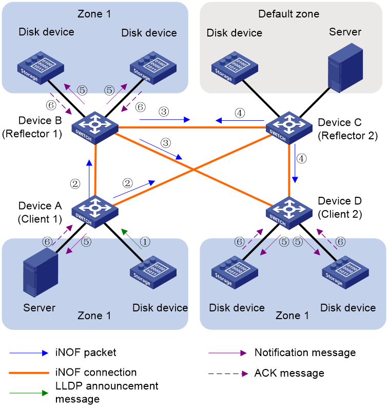
In the iNOF network shown in Figure 8, servers 10, disk devices 11 to 15 belong to the same custom zone, zone 1. Server 20 and disk device 21 belong to the default domain. Device A and Device D are clients, Device B and Device C are two backup reflectors, all iNOF switches belong to AS 65000, and are part of the same cluster. Both hosts and iNOF switches must support and enable the LLDP feature. When a host (assumed to be disk device 11) connects to an iNOF switch, the message exchange process between devices is as follows:
1. The host proactively sends an LLDP advertisement message to the directly connected iNOF switch (Device A), which records LLDP neighbor change information and subscribes to network information change messages.
2. After receiving the LLDP advertisement message, the iNOF switch processes it as follows:
a. Maintains the local host information database.
The iNOF switch uses "ChassisID+PortID" as a key to accurately search the local host information database.
- If a corresponding record is found, the host is considered already joined, the host information aging timer is updated, and other parameter values are compared for changes. If there are changes in other parameters, the local corresponding record is updated. If not, no further action is taken.
- If no corresponding record is found, the host is considered new. The iNOF switch creates a record for the host in the host information database and starts the host information aging timer.
b. Sends a notification message to inform about the network information change.
- For new hosts who have joined and subscribed to network information change messages (disk device 11), the iNOF switch announces the status information of all devices within the domain (server 10, disk devices 12 to 15) to the new host.
- For directly connected hosts belonging to the same iNOF domain and subscribed to network information change messages (server 10, disk devices 12 to 15), the iNOF switch announces the information of the newly joined host to other hosts.
c. Sends an iNOF message to inform the iNOF reflectors.
Device A extracts the LLDP neighbor change information and encapsulates it into a BGP message as an iNOF route, which is then announced to reflectors Device B and Device C via iBGP connections.
3. Server 10 and disk device 11 reply with an ACK message, indicating that they have received the announcement.
4. After receiving the iNOF message, Device B processes it as follows:
a. Reflects the iNOF route received from Device A to Device C and Device D.
Since Device B and Device C belong to the same cluster and are two backup reflectors, when Device C receives the iNOF route reflected by Device B, it directly discards the route.
b. Sends a notification message to inform about the network information change.
Device B checks the local host information database for other hosts that are directly connected, belong to Zone 1, and have subscribed to network information change messages. Assuming disk device 14 has subscribed to network information change messages and disk device 15 has not, Device B sends an announcement to disk device 14 but not to disk device 15.
5. Disk device 14 replies with an ACK message, indicating that it has received the announcement.
6. Device C processes it as follows:
a. Reflects the iNOF route received from Device A to Device B and Device D.
Since Device B and Device C belong to the same cluster and are two backup reflectors, when Device B receives the iNOF route reflected by Device C, it directly discards the route.
b. Device C checks the local host information database and finds no host belonging to Zone 1, so Device C does not need to send a notification message.
7. Device D sends a notification message to inform about the network information change.
Device D checks the local host information database for other hosts belonging to Zone 1 who have subscribed to network information change messages. Assuming both disk devices have subscribed, Device D sends an announcement to disk devices 12 and 13.
8. Disk devices 12 and 13 reply with an ACK message, indicating that they have received the announcement.
After convergence, all hosts within Zone 1 are able to synchronize information, and each host is aware that there are 6 hosts in Zone 1: server 10, disk devices 11 to 15.
Host leaving
When the following conditions occur, the iNOF switch considers the host to have left and initiates the host departure announcement process:
· LLDP messages timed out on the iNOF switch side.
· The interface directly connected between the iNOF switch and the host becomes Down.
· The iNOF switch encounters PFC (Priority-based Flow Control) deadlock, preventing the host's messages from being forwarded by the switch.
· iNOF domain configuration changes lead to host routes becoming unreachable.
When a host (assumed to be disk device 11) leaves, the message exchange process between devices is as follows:
1. The directly connected iNOF switch processes it as follows:
a. Deletes the corresponding record from the local host information database.
b. Informs other hosts directly connected within the same iNOF domain and subscribed to network information change messages that a device has gone offline.
c. Informs the iNOF reflectors that a device has gone offline.
2. Other iNOF switches process it as follows:
a. Informs other hosts directly connected within the same iNOF domain and subscribed to network information change messages that a device has gone offline.
b. For iNOF reflectors, inform other iNOF reflectors and connected clients that a device has gone offline.
3. Processing on other hosts:
Other hosts send an ACK message to the iNOF switch, acknowledging awareness of the host going offline. If the iNOF switch does not receive an ACK from the host, it will resend the notification message.
After convergence, all hosts within Zone 1 are able to synchronize information, and all hosts subscribed to network information change messages are aware that there are 5 hosts in Zone 1: server 10, disk devices 12 to 15.
BFD-based link failure detection
When iNOF reflectors run on a network, they rely on BGP, and thus support BFD configuration.
Bidirectional forwarding detection (BFD) provides millisecond-level link failure detection. It can detect and monitor the connectivity of forwarding paths to detect communication failures quickly. Once a communication failure is detected, BFD can report the failure to upper-layer applications.
The collaboration between iNOF and BFD is to associate BFD with iNOF through BGP and achieve fast failure detection for the links between iNOF switches.
Establishing BFD sessions
Bidirectional Forwarding Detection (BFD) does not have its own neighbor discovery mechanism and relies on associated upper-layer protocols to establish sessions. When an upper-layer protocol establishes a new neighbor relationship, it announces the neighbor's parameters and detection parameters (including the destination and source addresses, etc.) to BFD. BFD then establishes a BFD session based on the received parameters.
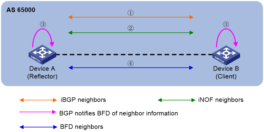
As shown in the following figure, in AS65000, Device A is a reflector, and Device B is a client. The process for establishing a session triggered by the linkage between iNOF and BFD is as follows:
1. Device A and Device B establish an iBGP connection.
2. Based on the iBGP connection, iNOF establishes an iNOF connection, where the status of the iNOF connection is completely consistent with the status of the iBGP connection.
3. After the iBGP connection is established, Device A and Device B announce neighbor information (including destination and source addresses, etc.) to their respective BFD modules.
4. The BFD module automatically establishes a BFD session based on the received neighbor information and parameters from the peer.
Figure 12 Establishing a BFD session
BFD notifies iNOF of link failures
After the BFD session is established, Device A and Device B periodically send BFD packets to each other. If one end does not receive a BFD packet from the session peer within the BFD detection time, it considers a failure to have occurred in the bidirectional forwarding path. The failure information is then notified to the upper-layer application serving that session, prompting the upper-layer application to take appropriate measures.
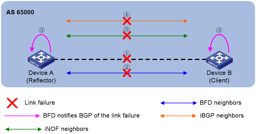
As shown in the following figure, the process for BFD to notify iNOF of a link failure detection is as follows:
1. A link failure occurs on Device A and Device B.
2. The BFD modules on Device A and Device B detect that the BFD neighbor is unreachable, and the local BFD session status changes to DOWN.
3. The BFD module notifies the local BGP process that the BFD neighbor is unreachable.
4. The local BGP process on Device A and Device B interrupts the iBGP neighbor relationship and announces this to the iNOF process.
5. The local iNOF connection on Device A and Device B is disconnected. The iNOF process considers the remote host to be offline. Subsequently, announcement messages are sent to hosts that are directly connected, within the same domain, and subscribed to network information change messages, indicating the remote host is offline. The reflector will also send iNOF messages to connected clients and other reflectors to notify them of the remote host's offline status.
Figure 13 Fault processing
Technical features implemented by H3C
H3C has extended the mature BGP technology to implement the iNOF networking across switches with the following features:
· iNOF connections are established based on BGP connections, using the TCP protocol at the transport layer to provide a stable connection for the transmission of iNOF information.
· Rich routing policies provided by BGP allow for flexible filtering and selection of iNOF routes.
· iNOF reuses the BGP route reflection function, which can effectively reduce the number of iNOF connections in large-scale iNOF networks, simplify network topology, and decrease network maintenance costs. Moreover, once an administrator configures iNOF domains and member hosts on the reflector, iNOF can automatically synchronize these settings to the clients, simplifying iNOF deployment and configuration.
· iNOF reuses BGP's GR (Graceful Restart) and NSR (Nonstop Routing) features to ensure the uninterrupted transmission of iNOF information during iNOF switch failover or BGP restart.
· Since iNOF reuses BGP connections and BGP supports linkage with BFD, iNOF can also quickly detect link failures using BFD.
· Leveraging various encryption methods for BGP sessions, such as MD5 authentication, GTSM (Generalized TTL Security Mechanism), and keychain authentication, can enhance the security of connections between iNOF switches.
Typical networkings
iNOF networking without reflectors deployed
As shown in the following figure, all servers are equipped with SNSD (Storage Network Smart Discovery) and multipathing software, and all disk devices have SNSD software installed. To enhance reliability, servers and disks are connected via Device A and Device B, respectively. Under normal circumstances, the multipathing software chooses to transmit packets between the server and the disk through Device A.
Deploy the iNOF function on both Device A and Device B to achieve the following goals:
· If there is a link failure between Device A and the disk device, Device A can notify the server immediately so that the multipathing software on the server can quickly switch to the server > Device B > disk device link to transmit packets;
· If the link between Device A and the disk device is restored, Device A can notify the server immediately so that the multipathing software on the server can quickly switch back to the server > Device A > disk device link to transmit packets.
Figure 14 iNOF networking without reflectors deployed

iNOF networking with reflectors deployed
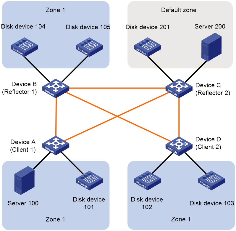
As shown in the following figure, an enterprise has established data centers in different locations, with disk devices and servers in these data centers interconnected via Ethernet. All servers are equipped with SNSD and multipathing software, and all disk devices have SNSD software installed. Deploy the iNOF function in the network to achieve the following goals:
· When a disk device joins, servers can detect it immediately and establish a connection with the disk device as soon as possible.
· When a disk device fails, servers can detect it immediately and quickly switch to a backup disk device.
· Assets can be divided into iNOF custom domains, with sporadic assets divided into the default domain, to isolate devices between different domains. For example, server 100 and disk devices 101 to 105 can be added to Zone 1 for use and management by the data department; server 200 and disk device 201 can be added to the default domain for centralized management by the IT department.
Figure 15 iNOF networking with reflectors deployed
Related documentation
· ODCC-2020-05016: Requirements and Testing Specifications for NVMe over RoCEv2 Network Control Optimization Technical
· China Mobile RoCE-SAN Solution v03 20210817
