- Released At: 18-12-2024
- Page Views:
- Downloads:
- Table of Contents
- Related Documents
-
VSRP Technology White Paper
Copyright © 2024 New H3C Technologies Co., Ltd. All rights reserved.
No part of this manual may be reproduced or transmitted in any form or by any means without prior written consent of New H3C Technologies Co., Ltd.
Except for the trademarks of New H3C Technologies Co., Ltd., any trademarks that may be mentioned in this document are the property of their respective owners.
The content in this article is general technical information, some of which may not be applicable to the product you have purchased.
Contents
Typical topology of the backup channel
Relationship between VSRP and various service modules
Master and backup election mechanism
Collaboration between VSRP and VRRP
Collaboration between VSRP and S-Trunk
VSRP control channel fast detection
ARP support for VSRP and VRRP group collaboration with the direct link used as the backup channel
ND support for VSRP and VRRP group collaboration with the direct link used as the backup channel
Implementing VSRP for DHCPv4 server and DHCPv6 server
Typical networking applications
Implementing VSRP for DHCPv4 relay and DHCPv6 relay
Implementing VSRP for IGMP/MLD
VSRP support for MEC (Layer 2 network)
VSRP support for MEC (Layer 3 network)
Overview
Technical background
As users' demands for network reliability increase, ensuring uninterrupted network transmission has become an urgent issue. This is particularly essential at key service entry or access points, such as corporate Internet gateways. If only one device is used at these points, regardless of its reliability, the system will inevitably bear the risk of network service interruptions due to single point failures, as shown in Figure 1. To address this, we typically adopt 1+1 redundancy backup at the device level. Especially for multi-service type route gateways, in addition to implementing 1+1 redundancy on hardware, we also deploy VSRP to backup various service data. This ensures that after a single point failure, when traffic is switched to another device, service data is not interrupted.

Benefits
Virtual Service Redundancy Protocol (VSRP) provides a device-level network reliability solution. In scenarios where a redundancy protocol (such as VRRP or S-Trunk) is deployed, user service data is backed up from the master (or primary) device to the backup (or secondary) device. When the master (or primary) device or link fails, user services are immediately switched over to the backup (or secondary) device. When the master (or primary) device or link fault recovers, user services switch back to the master (or primary) device, ensuring service continuity.
As shown in Figure 2, in practical applications, the most common network configuration for VSRP is 1+1 device-level backup, also referred to as dual-node hot backup. That is, two devices of the same model and the same software and hardware configurations are deployed at important nodes in the network to enhance network reliability as follows:
· One device serves as the master device. The master device handles service operations, forwards service traffic, and backs up data from service modules.
· Another device operates as a backup device. When the master device is working correctly, the backup device does not forward service traffic and only backs up the data of the service module. In case of a fault with the master device, the backup device is able to take over the role of the master device, ensuring service continuity.
|
|
NOTE: VSRP is based on the dual-node hot backup model, expanding it across multiple devices, allowing device-level redundancy backup between multiple devices. This document typically introduces the dual-node networking scenario in VSRP. |

Basic concepts of VSRP
Concepts
VSRP group
A VSRP group contains two peer devices that are enabled with VSRP.
VSRP peer
The member devices in a VSRP group are the peer of each other, with one as master and the other as backup. You must configure the peer IP address on each device to create a VSRP group.
Device role in the VSRP group
In a VSRP group, device roles include master and backup. The role of a device affects the direction of data backup in the service module. Most service modules back up data from the master to backup. Some modules perform bidirectional backup between master and backup devices.
VSRP instance
The VSRP instance is used for managing data backup between two devices in the VSRP group. Under the VSRP instance, the administrator can specify parameters such as VSRP peer, backup mode, and backup trigger condition. When the service module uses the VSRP instance, data backup is performed according to the parameters defined in the VSRP instance.
Create multiple instances and specify different peers in each instance to achieve data backup among multiple devices.
Create multiple instances, specifying different backup parameters in each instance, to meet the backup requirements of different business data.
VSRP channel
The VSRP peers in a VSRP group synchronize VSRP instance state information and service data by establishing TCP control and data channels.
· Control channel—Used for the transmission of VSRP protocol packets, to determine the role of the device in the VSRP group. In a VSRP group, all VSRP instances use the same control channel.
· Data channel—Once a service module is associated with multiple VSRP instances, a service data channel is created on the devices at both ends of these instances. This channel is used to synchronize the service data (real-time state and service operation information). This backup mechanism ensures that the backup device takes over the services when the master fails.
After completing the configuration for VSRP and ensuring the route between the local IP address and peer IP address used by the backup channel is reachable, the master device and backup device will automatically establish a backup channel.
Master/backup switchover
In normal operation of VSRP, the master device is responsible for forwarding user traffic, while the backup device serves only as a backup and does not forward user traffic. When the master device or a link fault occurs, the backup device switches over to become the new master device, taking over the process of forwarding user traffic from the original master device. This process is called a switchover.
Switch-back
When the original master device or link fault recovers, the original master device resumes its master role and the original backup device resumes its backup role. The process, which involves traffic switching back to the original master device and being forwarded by it, is referred to as switch-back.
Typical topology of the backup channel
Depending on the configuration method of the backup channel, VSRP supports the following two typical networking methods:
· Direct networking. The master device and the backup device are directly connected, and the direct link is used as the backup channel, as shown in Figure 3. Using the direct link as the backup channel provides higher backup efficiency, but it requires occupying an interface.
· Networking across intermediate device groups. Use the uplink of the cross-intermediate device as a backup channel, as shown in Figure 4. Using the cross-device link as a backup channel does not need to occupy the interface, but the backup control messages and data backup packets will be mixed with the service packets. As a best practice, use dedicated VLAN or subinterface to isolate traffic.
|
|
NOTE: To enhance the reliability of the backup link and avoid issues caused by single link faults that result in failed backups, use the aggregate link as the backup channel. |
Figure 3 Using direct link as the backup channel

Figure 4 Using cross-device link as the backup channel

Relationship between VSRP and various service modules
In a VSRP network, two issues need to be addressed: one is determining which device processes the traffic, and the other is how to back up the business data.
As shown in Figure 5, in the dual-node backup network setup:
· Use Virtual Router Redundancy Protocol (VRRP) or Smart Trunk (S-Trunk) to determine which device is the master and which is the backup in a dual-node backup scenario. Traffic is passed through the master device.
· VSRP, as a bridge module, collaborates with VRRP, S-Trunk, and service modules. It establishes a unified backup platform for redundancy backups between master and backup devices across various user services.
¡ VSRP determines the master and backup in VSRP data backup based on VRRP and S-Trunk's master and backup.
¡ VSRP advertises the master and backup data to the service module during the data backup process, guiding the backup operations of the service module.
¡ VSRP advertises parameters such as backup channel, backup time interval or traffic threshold to the business module, guiding the data backup of the service module.
· The service module implements data backup, allowing traffic to switch to another device. This other device will have the corresponding service data to process service packets, ensuring uninterrupted services. For example, VSRP is applied in the Broadband Remote Access Server (BRAS) network. It performs VSRP for BRAS devices in the network distribution layer. The master and backup devices back up the user's BRAS authentication information, charging information, and customer management information through the data backup channel. This ensures the continuous operation of the BRAS system and improves its reliability.
The service modules that currently support VSRP include Address Resolution Protocol (ARP), Neighbor Discovery (ND), DHCPv4 server, DHCPv6 server, DHCPv4 relay, DHCPv6 relay, Internet Group Management Protocol (IGMP), Multicast Listener Discovery (MLD), IP over Ethernet (IPoE), PPP over Ethernet (PPPoE), Layer 2 Tunneling Protocol (L2TP), Portal, Network Address Translation (NAT), and Multi-access Edge Computing (MEC).
|
|
NOTE: Support for service modules varies by device model. |
Figure 5 Relationship between VSRP and various service modules

Master and backup election mechanism
Collaboration between VSRP and VRRP
About collaboration between VSRP and VRRP
VRRP uses a set of routers (usually two) within the local area network (LAN) to form a VRRP group. Functionally, the VRRP group acts as a virtual router. The VRRP group assigns two roles to physical devices: Master and backup.
The VRRP group supports two working modes: Standard mode and load balancing mode.
· In the standard mode:
¡ The master router forwards traffic, and the hosts within the local area network (LAN) communicate with the external network through the master router.
¡ The backup router is in a listening state and cannot forward packets.
· In the load balancing mode:
Both the master router and the backup router can forward packets.
Regardless of whether VRRP operates in the standard mode or load balancing mode, in a VSRP network, the master and backup roles of the two devices in the VSRP instance are determined by the roles of the devices in the VRRP group. The master router in the VRRP group acts as the master device in the VSRP group, while the backup router in the VRRP group serves as the backup device in the VSRP group.
Election mechanism of VRRP master and backup devices
During network deployment, the network administrator needs to configure the VRRP priorities for these two devices. The rules for electing the role of the VRRP device are as follows:
· The router with a higher priority becomes the master router.
· The router with a lower priority becomes the backup router.
· If the priorities are the same, the device with the larger IP address on the interface where the VRRP group is located becomes the master router.
Working mechanism of the VRRP master/backup networking scenario
VRRP master and backup group networking refers to the VRRP group operating in standard protocol mode. Only the master router forwards packets while the backup router does not. The principle behind its implementation is:
1. The administrator assigns the virtual IP (VIP) address of the VRRP group as the gateway (GW) on the host.
2. The host transmits an ARP/ND message to the gateway (GW), requesting the gateway's MAC address.
3. The master router uses its local host's virtual MAC (VMAC) address to respond to the host's ARP/ND request, while the backup router does not respond to the host's ARP/ND request.
4. The host maintains the correspondence between the master router's virtual MAC (VMAC) address and the gateway (GW) IP address in the ARP table, and transmits messages to the Master router for processing.
The roles of the primary and backup devices in VSRP are the same as those in the VRRP group. The master router in the VRRP group serves as the master device in VSRP, and the backup router in the VRRP group serves as the backup device in VSRP, as shown in Figure 6. For the processing of backup data in this scenario, see the sections for implementation of VSRP with service modules.
Figure 6 VSRP and VRRP group collaboration (in normal case)

Working mechanism of the VRRP dual-active networking scenario
In the standard VRRP mode, only the master router can forward packets, and the backup router is in a listening state, unable to forward packets. To improve device utilization, we hope that while VRRP provides gateway redundancy backup functions, both devices can process services and forward packets, that is, VRRP supports dual-active networking. In VRRP dual-active networking, the devices in the VRRP group also fall into two roles: Master router and backup router. The master and backup roles of the two devices in the VSRP instance are still determined by the roles of the devices in the VRRP group after collaboration between VSRP and VRRP. The master router in the VRRP group acts as the master device in the VSRP group, and the backup router in the VRRP group serves as the backup device in the VSRP group.
There are two implementation methods for VRRP dual-active networking.
1. Dual-active mode is achieved by creating multiple VRRP groups based on standard protocol patterns, as shown in Figure 7.
For VRRP:
¡ In VRRP group 1, designate Router A as the master device and Router B as the backup device.
- Router A uses its local host's virtual MAC (VMAC) address to respond to the ARP/ND request from Host A and Host B.
- The destination IP address of the packets sent by Host A and Host B is the virtual IP (VIP) address of VRRP group 1, and the destination MAC address is the virtual MAC (VMAC) address of Router A.
- Router A forwards the messages from Host A and Host B.
¡ In VRRP group 2, set Router A as the backup device and Router B as the primary device.
- Router B responds to the ARP/ND request of Host C using its local host's virtual MAC (VMAC) address.
- The destination IP address of the message transmitted by Host C is the virtual IP (VIP) of VRRP group 2, and the destination MAC address is the virtual MAC (VMAC) of Router B.
- Router B forwards the packet from Host C.
For VSRP:
You can associate VSRP instance 1 with VRRP group 1, and associate VSRP instance 2 with VRRP group 2. In this way, the master and backup roles in VSRP is identical to those in the VRRP group.
¡ In VSRP instance 1, Router A serves as the master VSRP device, while Router B acts as the backup VSRP device.
¡ In VSRP instance 2, Router B serves as the master VSRP device, while Router A acts as the backup VSRP device.
This thus achieves bi-directional backup of service data, ensuring the data consistency on both Router A and Router B.
Figure 7 VRRP and VSRP collaboration in a dual-active networking (multiple VRRP groups in standard mode)

2. Implement dual-active mode by configuring VRRP load balancing mode, as shown in Figure 8.
Create a VRRP group to operate in load balancing mode. VRRP will still elect the master router and backup router. VRRP uses virtual MAC (VMAC) address and virtual forwarder technology, allowing traffic from different hosts to be transmitted to different routers, and each router in the backup group can forward the traffic. The message forwarding process in the load balancing mode is roughly as follows:
a. The master router will generate a virtual MAC (VMAC) address for every router in the backup group.
b. The master router responds to the ARP/ND requests from the host using different virtual MAC (VMAC) addresses. For instance, it uses the VMAC address of Router A to respond to the ARP/ND requests from Host A and uses the VMAC address of Router B to respond to the ARP/ND requests from Host A.
c. The destination IP address of the message transmitted by Host A is the virtual IP (VIP) of backup group 1, and the destination MAC address is the virtual MAC (VMAC) of Router A.
d. Host B transmits a message with the destination IP address being the virtual IP (VIP) of backup group 1, and the destination MAC address being the virtual MAC (VMAC) of Router B.
e. Router A forwards the message from Host A.
f. Router B forwards the data packets from Host B.
The master and backup device roles in VSRP are the same as in the VRRP group. For data backup processing in this scenario, see the sections on the implementation of VSRP with service modules.
|
|
NOTE: VRRP load balancing mode uses the same master election, preemption, master/backup switchover, and switchover upon failure recovery mechanisms as the standard mode. |
Figure 8 VRRP and VSRP collaboration in a dual-active network (in VRRP load balancing mode)

Master/backup switchover mechanism
|
|
NOTE: The master/backup switchover mechanisms of VRRP master/backup networking and dual-active networking are identical. |
The VRRP protocol stipulates that the master router periodically transmits VRRP messages, advertising its configuration (such as priority) and work status in the virtual router. The backup router determines whether the baster router is operating correctly by receiving the VRRP messages.
When the master router suffers a network outage and cannot transmit VRRP messages, the backup router does not immediately obtain its status. The backup router waits for a period of time, and if it has not received any VRRP messages, it considers the master router unable to function correctly and switches to master. The new master router sends an ARP broadcast request with its source MAC as its local host's virtual MAC to the host, which then refreshes its local MAC address table. This allows the host to forward messages to the new master router for processing, and for the new master router to carry on forwarding traffic.
VSRP follows VRRP group for master/backup switchover, where VSRP takes Router B as the master device, performing a role switchover, as shown in Figure 9. For the processing of backup data in this scenario, see the sections for implementation of VSRP with service modules.
Figure 9 VRRP and VSRP collaboration (master/backup switchover)

Switch-back working mechanism
|
|
NOTE: The switch-back mechanisms of VRRP master/backup networking and dual-active networking are identical. |
After VRRP switchover, if the previously faulty master device (Router A) recovers, VRRP is required for the initially created router to work in backup status, thus Router A is currently a backup router. However, Router A (Backup router) has a higher priority than the existing master router (Router B). At this moment, the working mode of backup router (Router A) (preemption and non-preemption mode) will determine whether to re-elect a master.
· Non-preemptive mode—When the backup router operates in non-preemption mode, it will not become the master router even if it is later configured with a higher priority, as long as the master router does not have any fault.
· Preemptive mode—If the backup router operates in preemption mode, it will compare its priority with the one in the advertisement message upon receiving a VRRP message. If its priority is higher than the current master router, it will preempt to become the Master router. Otherwise, it will maintain its backup status.
By default, the routers in the backup group operate in preemption mode with a delay time of 0 centiseconds. If Router A is restored, it will be immediately re-elected as the Master router and traffic will switch back to being forwarded by Router A.
VSRP performs switchover according to the VRRP group, that is, it switches Router A back to the master device state, and Router B back to the backup device state. For the processing of backup data in this scenario, please refer to the section on the implementation of VSRP technical support in the business module.
Collaboration between VSRP and S-Trunk
About collaboration between VSRP and S-Trunk
Smart Trunk (S-Trunk), an H3C proprietary protocol, is used in the networking environment of MPLS L2VPN where the customer edge (CE) is dually connected to the provider edge (PE). S-Trunk is a cross-device link aggregation mechanism. By aggregating links between multiple devices, the reliability is elevated to the device level.
The S-Trunk network model primarily defines the following concepts:
· S-Trunk group: A link aggregation group formed by aggregating the interfaces on two PE devices together.
· Device priority in the S-Trunk group: Used for deciding the primary and backup state of two PE devices within the same S-Trunk group.
· In the S-Trunk group, the roles of devices: Devices in the S-Trunk group are categorized as the primary device and backup device. The device with a higher priority is the primary one, while the one with a lower priority serves as the backup. The backup device will only switchover to become the primary device if the primary device experiences a fault or under certain triggered conditions.
· The S-Trunk group member interfaces: The interfaces, which join the S-Trunk group, form a backup within the same S-Trunk group.
· The role of interfaces in the S-Trunk group: The interfaces in the same S-Trunk group on two PE devices serve as either a primary interface or a secondary interface.
In S-Trunk networking, the role of the S-Trunk group's interface members determines whether to forward traffic. Only the primary interface can forward traffic.
· Under normal circumstances, the member interface on the main device is the primary interface, and the member interface on the backup device is the secondary interface.
· The role of the S-Trunk group member interface will switch over between primary and secondary based on the interface connectivity status. If the primary interface faults, the secondary interface will switchover to become the primary interface and forward the traffic.
In VSRP networking, after linking VSRP and S-Trunk, the master and backup roles of two devices in the VSRP instance are determined by the roles of the S-Trunk group member interfaces. The device belonging to the primary interface in the S-Trunk group serves as the primary device in the VSRP group, and the device belonging to the secondary interface in the S-Trunk group serves as the backup device in the VSRP group.
Working mechanism of S-Trunk primary and secondary group networking scenario
When linking VSRP and S-Trunk together, after successfully establishing the S-Trunk group, under normal circumstances, member interfaces on the primary device within the S-Trunk group perform packet forwarding. As shown in Figure 10, under normal circumstances, because PE 1 has a higher S-Trunk priority, it is selected as the primary device for the S-Trunk. The LAGG 1 on PE 1 serves as the primary interface for the S-Trunk, and its link state is UP. PE 2 is the backup device for the S-Trunk, and its LAGG 1 is the backup interface for S-Trunk, with its link state being S-Trunk DOWN. User traffic on the CE side is forwarded through LAGG 1 on PE 1.
The roles of the primary and secondary devices in VSRP correspond to the roles of the member interfaces in the S-Trunk group. PE 1 is the primary device for VSRP, while PE 2 is the secondary device. For the processing of backup data in this scenario, see the sections for implementation of VSRP with service modules.
Figure 10 VSRP and S-Trunk group collaboration (in normal cases)

Normal working mechanism of the S-Trunk group
1. A link fault in the main member interface of the S-Trunk group leads to a switchover.
When a link fault occurs at the primary interface in the S-Trunk group, the traffic is forwarded through the standby interface. As shown in Figure 11, if a link fault occurs between CE and PE 1, the Hello message transmitted from PE 1 to PE 2 carries the fault information of PE 1's LAGG 1. After PE 2 receives the Hello message and detects the fault of PE 1's LAGG 1, the roles of the primary and standby devices remain unchanged. PE 2's LAGG 1 becomes the primary interface, and the link state changes to UP. In this way, the traffic from CE is transmitted through PE 2, achieving the goal of protecting CE's traffic.
The role of the primary and backup devices in VSRP corresponds to the role of the S-Trunk group member interfaces. Switch PE 2 to the new primary device, and switch PE 1 to the backup device. For the processing of backup data in this scenario, see the sections for implementation of VSRP with service modules.

2. The primary device in the S-Trunk group fails, resulting in a switchover.
After the primary device in the S-Trunk group fails, the traffic is forwarded by the secondary interface. As shown in Figure 12, if PE 1 fails and PE 2 has not received the Hello message transmitted from PE 1 within the timing limit, the roles of the devices remain the same, with LAGG 1 on PE 2 becoming the primary interface and the link state turning to UP. This way, the traffic from CE will pass through PE 2, achieving the goal of protecting the CE's traffic.
The role of the master and backup devices in VSRP corresponds to the role of the S-Trunk group member interfaces, with PE 2 switched to the new primary device and PE 1 switched to the secondary device. For the processing of backup data in this scenario, see the sections for implementation of VSRP with service modules.
Figure 12 Collaboration between VSRP and S-Trunk (PE 1 fault leading to switchover)

Failover mechanism in the scenario of the S-Trunk primary and secondary networking
In a VSRP network setup, for a smooth switchover of traffic between two devices, as a best practice, make sure the primary and secondary devices are completely symmetrical, meaning the model and both software and hardware (HW) configurations of the two devices are the same. The network administrator might plan the device with better performance and higher configuration as the primary device based on the actual network situation. Thus, when an error recovery causing a correct switchover in the S-Trunk occurs, and the network returns to a normal state, by default, the S-Trunk will activate a delay switch-back timer. After this timer times out, the S-Trunk will restore PE 1's LAGG 1 to primary state, and PE 2's LAGG 1 to standby state, and traffic will switch back to PE 1.
The role of the primary and secondary devices in VSRP corresponds to the role of the S-Trunk group member interfaces, restoring PE 1 to the primary device and PE 2 to the standby device. For data backup processing under this scenario, refer to the chapter on the implementation of the multiple-device backup technique supported by the business module.
If after the switchover, the current primary/secondary state of the dual nodes can meet business requirements, to avoid traffic changeover during the switchback process, the administrator can choose to turn off the switchback function.
Working mechanism of S-Trunk dual-active networking
In the S-Trunk primary-secondary group networking, only the interfaces with the primary state in the S-Trunk group forward traffic, while the interfaces in the Secondary state are shut down and cannot forward traffic. To improve link usage, we can force the two member interfaces of the S-Trunk group to be in the primary state at CLI, enabling both member interfaces to process business and forward messages while S-Trunk provides redundancy backup function, that is, S-Trunk supports dual-active networking.
In the S-Trunk dual-active networking scenario, VSRP elects the primary and secondary device roles using anti-split-brain mechanisms to guide the business modules in data backup. For the processing of backup data in this scenario, see the sections for implementation of VSRP with service modules.
|
|
NOTE: In a dual-active S-Trunk group network, both member interfaces in the S-Trunk group are in the primary state. Therefore, there are no switchover or fallback situations in the dual-active S-Trunk network. |
Figure 13 Collaboration between VSRP and S-Trunk (dual-active S-Trunk networking)

Anti-brain-split mechanism
As shown in Figure 14, a network outage OR VRRP/S-Trunk protocol failure may cause both PE 1 and PE 2 to believe they are the primary device for VRRP/S-Trunk. This phenomenon is called split-brain. In a split-brain situation, the absence of a backup device can severely impact, or even halt, data backup for business modules.
To solve the split-brain issue and allow the business module to continue data backup, VSRP gets dual master from VRRP/S-Trunk. Immediately, VSRP will pass its control channel to select the primary and standby devices for VSRP. The rule is to compare the local and peer's IP addresses. The device with a larger IP address is the primary for VSRP and the one with a smaller IP address is the backup, preventing split-brain issues.
Figure 14 VSRP anti-brain-split

VSRP modes
The backup modes of VSRP include two types: hot backup and warm backup.
· Hot backup: When the backup device receives the backup information from the primary device, it immediately sends out the backup information to the forwarding plane. In this way, if a fault occurs to the primary device, the standby device can guide the packet forwarding instantly, enabling swift switchover to the backup device. Hot backup is applicable for 1+1 backup scenarios (one primary device plus one backup device).
· Warm backup: Upon receiving backup information from the primary device, the standby device doesn't immediately distribute the backup data to the forwarding plane. It only starts this process once the primary device experiences a fault causing a switchover in the primary and secondary device states. The time taken for services to switch over to the standby device in a warm backup scenario is slightly longer than in a hot backup scenario. Warm backup is suitable for N+1 backup scenarios (N primary devices plus one standby device). For these N+1 backup scenarios, since there's much backup data, immediate distribution of backup information to the forwarding plane might result in the majority of forwarding entries being temporarily occupied by unused data, while the immediate data needed cannot access entry resources for backup. For example, if primary devices A, B, C, and D share Standby device E with a forwarding entry specification of 4,000, each device A, B, C, and D has 2,000 data entries. When these are backed up to E, at most 4,000 entries can be distributed; the remaining entries can't be pushed out, and E cannot create new forwarding entries until the existing ones age. If the primary device fails and service changeover occurs to E for processing, E might be impacted due to a lack of business data.
In practical networking, the hot backup mode is more commonly used. This article focuses on the description of the hot backup mode.
VSRP control channel fast detection
By default, a VSRP group detects the state of the failover link based only on the state of the TCP control channel. To fast detect the state of the failover link, you can perform the following tasks:
1. Use NQA or BFD to monitor the state of the failover link.
2. Establish the collaboration between the failover link state and NQA or BFD through the Track function.
A VSRP group operates differently depending on the state of the track entry associated with the VSRP group:
· When the track entry is in Positive or NotReady state, a device attempts to establish a TCP control channel with its peer.
· When the track entry changes to Negative state, the device terminates the TCP control channel.
Implementing VSRP for ARP/ND
Overview
The support for VSRP function in ARP/ND allows the ARP/ND entries of the master and backup devices under hot backup mode to remain synchronized. When a traffic switchover occurs, the new master device can perform fast forwarding of traffic without the need to relearn ARP/ND entries, thereby enhancing the reliability of ARP/ND service.
Operating mechanism
The basic operation mechanism of ARP supporting VSRP is similar to that of ND supporting VSRP. This article takes the example of ARP supporting VSRP's basic operation mechanism.
The basic operation mechanism of ARP supporting VSRP is as follows:
1. The instance of multiple device backup determines the master and backup roles of the devices.
2. Once the ARP function is bound to the VSRP instance on the interface, the ARP module begins to batch backup ARP entries. The master and backup devices each transmit ARP entry information from interfaces in the up state that are bound to the VSRP instance, passing it through the business data channel to the VSRP peer. The master and backup devices add ARP entries based on the received ARP entry information. Once all ARP entry information from the interfaces bound to the VSRP instance has been transmitted to the VSRP peer, the batch backup phase of the ARP module ends, entering into the real-time backup phase.
3. The ARP module performs real-time backup. The master and backup devices check every 0.1 seconds for changes in the ARP entries of the interfaces in the 'up' state bound to the VSRP instances. If changes occur, the devices transmit the modified entry information to the VSRP peer for backup.
4. Through the batch backup and real-time backup of entries, the ARP entries of the interfaces bound with multiple backup instances on the master and backup devices can be synchronized. This way, when a traffic switchover occurs between the primary and backup devices, the new master device does not need to relearn the ARP entries.
Whether it's a master/backup network or a dual-active network, regardless of two devices running normally, or in the case of a smooth switchover or a switch-back scenario, as long as ARP/ND detects an interface up and learns a new ARP/ND entry, it will be backed up to the peer device. If the backup link fails, the backup will stop.
ARP/ND does not support the standby mode. If you only want to implement ARP/ND service backup, you do not need to deploy VRRP and S-Trunk.
ARP support for VSRP and VRRP group collaboration with the direct link used as the backup channel
As shown in Figure 15, the upstream link of the access device uses OSPF for route learning and advertisement. VSRP is implemented between access devices Device A and Device B with the specific requirements as follows:
· Run the VRRP protocol on a subinterface connected to the customer site via the access device, and terminate the VLAN 10 used for VRRP protocol message interchange on this interface.
· The access device uses a direct link to construct a VSRP data channel, which is used for backing up ARP entry information.

ND support for VSRP and VRRP group collaboration with the direct link used as the backup channel
As shown in Figure 16, VSRP is configured for access devices Device A and Device B. The specific requirements are as follows:
· Run the VRRP protocol on a subinterface connected to the customer site by the access device and terminate VLAN 10 in the upstream packets on this subinterface.
· The access device uses a direct link to establish a VSRP data channel, which is used for backing up ND entry information.

Implementing VSRP for DHCPv4 server and DHCPv6 server
Overview
The DHCP server supports the function of VSRP, which can realize the batch and real-time backup of DHCP service data (including legal leases and conflicting leases) through the data backup channel. This ensures a smooth switchover to the standby DHCP server when the primary DHCP server has a fault. Thus, it reduces the risk of DHCP service interruptions and enhances the reliability of the DHCP service.
In the current software version, DHCP VSRP is often used in the BRAS network environment, in conjunction with IPoE, PPPoE and other access functions, to provide IPv4 or IPv6 address information for clients that need to connect.
|
|
NOTE: The implementation of VSRP for DHCPv6 server is consistent with the implementation of VSRP for DHCPv4 server. The term "DHCP server" in this chapter refers to both DHCPv4 and DHCPv6 servers. |
Operating mechanism
The basic operation mechanism of the DHCP server supporting VSRP is as follows:
1. VSRP establishes the master and backup roles of two devices in a VSRP instance.
2. Configure the address pool on the DHCP server to associate with multiple backup instances. When the interface names of the master and backup DHCP servers connected to the DHCP client are different, it is also necessary to bind the multiple backup instances to the interface connected between the DHCP server and client.
3. Once the address pool is associated and active with the VSRP instance, the DHCP server where the address pool is located serves as the primary device when the VSRP instance is in the primary state. Otherwise, the server serves as the backup device. Only the primary DHCP server can allocate address leases to the DHCP client. The backup DHCP server cannot allocate leases to the clients.
4. A TCP-based DHCP data backup channel is established between the primary and secondary DHCP servers. The primary DHCP server will transmit large amounts of existing DHCP business data in bulk to the secondary server for backup. When a new DHCP user comes online, the primary DHCP server will back up the newly generated business data to the secondary server in real-time.
5. When a switchover or a switchback happens in VSRP, the main DHCP server syncs business data with the backup DHCP server, and users will be switched from the original main DHCP server to the backup DHCP server. Subsequently, the new main DHCP server will carry out the allocation of leases and back up the generated business data to the new backup DHCP server. If a fault occurs with the backup device or the data backup channel, backup operations will no longer be executed.
In an S-Trunk dual active group networking setup, after setting the backup mode of the VSRP instance to a dual active hot backup mode, the primary DHCP server and the backup DHCP server are both working, sharing the user traffic load between them. Even in this networking environment, the VSRP module can still determine the master and backup device roles based on the VSRP instance. The interworking mechanism of DHCP and VSRP is the same as that under the master and backup networking. Data on the master device is automatically backed up to the backup device.
|
|
IMPORTANT: The primary application of S-Trunk dual-active networking is in DHCPv4 relay and DHCPv6 relay. The DHCPv4 server does not support S-Trunk dual-active networking, and it is only when the user goes online through NDRS that the DHCPv6 server will support S-Trunk dual-active networking. |
Typical networking applications
As shown in Figure 17, the DHCP client accesses the BRAS access device via a Layer 2 network in IPoE mode, and the BRAS access device is connected to the DHCP server. In order to enhance the reliability of DHCP services, VSRPs are deployed between DHCP server A and DHCP server B. DHCP server A is the primary device, and DHCP Server B is the backup device. If a fault occurs in DHCP server A, DHCP server B will take over its tasks, thus enhancing the reliability of the DHCP services.

Implementing VSRP for DHCPv4 relay and DHCPv6 relay
Overview
The DHCP relay supports VSRP function. This can be achieved through a data backup channel for bulk and real-time backup of DHCP business data (DHCP relay user address entries). It ensures a smooth switchover to the backup DHCP relay when the primary DHCP relay agent faults, thereby reducing the risk of DHCP relay service interruptions and improving the reliability of DHCP relay services.
At present, the DHCP relay VSRP function is frequently used in the BRAS network environment, in concert with access functions such as IPoE and PPPoE. It provides necessary information such as IP address to the clients needing access.
|
|
NOTE: The implementation principle of VSRP function support in DHCPv6 relay is basically consistent with that of DHCPv4 relay. The content of this chapter involves DHCP relay, including both DHCPv4 and DHCPv6 relay. |
Operating mechanism
The basic operating mechanism for VSRP support in DHCP relay is as follows:
1. Determine the primary and backup roles of two devices in a VSRP instance using VSRP.
2. After associating the interface of the DHCP client with multiple backup instances through configuration, a DHCP data backup channel based on a TCP connection will be established between the primary and standby DHCP relay. The DHCP module will use this channel to back up the user address entries recorded by the primary DHCP relay to the standby DHCP relay.
3. Once the data backup channel is successfully established, the primary DHCP relay will transmit a large amount of recorded DHCP business data in batches to the standby DHCP relay for backup. When a new DHCP relay user comes online, the primary DHCP relay will real-time back up the newly generated business data to the standby server.
4. When a switchover or switchback occurs in VSRP, the primary DHCP relay synchronizes business data with the standby DHCP relay, and users are switched from the original primary DHCP relay to go online on the standby DHCP relay. Subsequently, the new primary DHCP relay will execute the task of data forwarding (DF), and the generated business data will be backed up to the new standby DHCP relay. If a fault occurs in the standby device or the data backup channel, backup operations will no longer be executed.
In the network configuration of the S-Trunk dual-active group, after setting the backup mode of the VSRP instance to hot backup in dual-active mode, the primary and secondary DHCP relay operate simultaneously, with user traffic shared between the primary and secondary relay. Under this network environment, VSRP modules can still determine the primary and secondary device roles based on the VSRP instance. The mechanism of DHCP and VSRP linkage is the same as that of the primary and secondary network links. Data on the primary device will be automatically backed up to the secondary device.
Typical network applications
As depicted in Figure 18, the DHCP client connects to the BRAS access device via a layer-two network in an IPoE manner, with the BRAS access device also acting as a DHCP relay connected to the DHCP server. To enhance the reliability of DHCP services, VSRP is deployed between DHCP Relay A and DHCP Relay B. Specifically, DHCP Relay A is the primary device, and DHCP Relay B serves as the backup. If a fault occurs with DHCP Relay A, DHCP Relay B will take over to continue its work, thus improving the reliability of DHCP services.

Implementing VSRP for IGMP/MLD
Overview
The IGMP/MLD supports a VSRP function, which can be enabled on the interfaces of two access devices connected to the customer site. The master device automatically backs up the IGMP/MLD multicast group information on this device to the backup device. When the master device encounters a fault, the backup device can take over the multicast traffic forwarding work based on the multicast forwarding table entries generated from the backed-up IGMP/MLD multicast group information, ensuring multicast services are not disrupted.
Operating mechanism
The basic operation mechanism of IGMP/MLD supporting VSRP is as follows:
1. The VSRP determines the master and backup roles of two devices in the VSRP instance.
2. After associating the multicast service with multiple backup instances through configuration, the IGMP/MLD module will create a business data channel between the master and backup devices. This business data channel is used for synchronizing IGMP/MLD multicast group information.
3. Upon successful establishment of the business data channel, the master and backup devices will real-time backup the IGMP/MLD membership report messages received from downstream devices to the opposite device, achieving bidirectional backup between the master and backup devices.
4. When a VSRP switchover occurs, the current master device quickly transmits an IGMP/MLD query message to downstream devices, triggering them to respond with an IGMP/MLD membership report message. This retrieves IGMP/MLD multicast group information, facilitating rapid backup. If the current backup device OR backup channel experiences a fault, the backup operation will not be executed.
In the hot backup mode of the S-trunk dual-active networking, IGMP/MLD supports the load sharing function of VSRP. Once the load sharing function of VSRP is configured on the device, the main and backup devices will form load sharing, and jointly forward multicast traffic. The main device forwards multicast traffic of multicast group addresses that are odd, while the backup device forwards multicast traffic of multicast group addresses that are even.
At this point, after the VSRP network switches, when the original master device or link fault recovers, you can choose to configure switch-back or not. On the two devices belonging to the same VSRP group, the switch back mode for multicast traffic forwarding needs to be consistently configured, meaning either both switch back or neither do.
· When both master and backup devices are configured not to switch back, all multicast traffic is continuously forwarded by the current forwarder device. The device that recovers from failure does not participate in forwarding the multicast traffic.
· When both the master and backup devices are configured for switchover, the current master device forwards multicast traffic with an odd number multicast group address, while the current backup device forwards multicast traffic with an even number multicast group address.
Typical network applications
As shown in Figure 19, users access the network through IPoE authentication and deploy VSRP on access devices Device A and Device B. Device A acts as the master device and Device B as the backup. Device A and Device B mutually back up IGMP/MLD multicast group information. If a fault occurs with Device A, Device B takes over and continues to operate, allowing multicast traffic to be forwarded with the multicast forwarding table entries generated on Device B, ensuring that multicast packet forwarding will not be disrupted.
Figure 19 Network diagram (IPoE scenario)

Implementing VSRP for IPoE
Overview
IPoE's support for VSRP functions can enhance the reliability of IPoE access services. Once the VSRP function for IPoE is configured on two BRAS devices, the master BRAS device will automatically back up IPoE user session information to the backup BRAS device. If a fault occurs with the master BRAS device, the backup BRAS device can take over and continue to work, ensuring that the IPoE user's service is not disrupted.
Operating mechanism
The basic operation mechanism of IPoE supporting VSRPs is as follows:
1. VSRP establishes the master and backup roles of two devices in a VSRP instance.
2. After associating the IPoE service with the VSRP instance through configuration, the IPoE service module will create a business data channel between the master and backup devices. This business data channel is used to synchronize the session information of IPoE users.
3. After the successful establishment of the business data channel, the master device rapidly backs up all data that need backup to the backup device. Subsequently:
¡ For IPoE users who are online, the IPoE module of the main device will incrementally backup their traffic update information to the backup device, according to the set traffic backup time interval OR traffic threshold.
¡ For session information of newly online IPoE users or authorization property changes of already online users, the IPoE module of the main device will back it up to the backup device in real time.
4. During switchover or switchback of VSRP, the IPoE module always takes the data from the current master device as the standard, automatically backing up the session information of the IPoE user from the master device to the current backup device. If the current backup device or backup channel encounters a fault, the backup operation will not be executed.
In the network built with VRRP or S-trunk dual-active group, VSRP can still determine the role of the master and backup VSRP devices. The IPoE and VSRP mechanism function the same way as they do in the master and backup network, where the data on the master device is automatically backed up to the backup device.
Typical network applications
As shown in Figure 20, the DHCP client connects to the BRAS access device via a Layer 2 network using the IPoE method. To improve the reliability of IPoE services, a VSRP is deployed between BRAS A and BRAS B. Here, BRAS A serves as the master device, and BRAS B serves as the backup device. When a fault occurs in BRAS A, BRAS B takes over to continue working, enhancing the reliability of IPoE services.

Implementing VSRP for PPPoE
Overview
The PPPoE function's support for VSRP can enhance the reliability of PPPoE access services. After configuring the PPPoE support for VSRP on two BRAS devices, the master BRAS device will automatically backup the session information of local PPPoE users to the backup BRAS device. If a fault occurs on the master BRAS device, the backup BRAS device can continue to work, ensuring that the PPPoE user service won't be disrupted.
Operating mechanism
The basic operation mechanism of PPPoE supporting VSRP is as follows:
1. The VSRP determines the master and backup roles of two devices in the VSRP instance.
2. After associating the PPPoE service with multiple backup instances through configuration, the PPPoE service module will create a service data channel between the main and backup devices. This service data channel is used to synchronize the session information of PPPoE users.
3. Upon successful establishment of the business data channel, the master device will quickly batch backup all required data to the spare device. Subsequently:
¡ For online PPPoE user traffic update information, the PPPoE module of the master device will perform an incremental backup to the backup device based on the set traffic backup time interval or traffic threshold.
¡ For the session information of new online PPPoE users OR the changed authorization properties of existing online users, the PPPoE module of the master device will back it up in real time to the backup device.
4. When a VSRP switchover or switch-back occurs, the PPPoE module always follows the data on the current master device, automatically backing up the session information of the PPPoE users of the current master device to the current backup device. If the current backup device has a fault OR there is a channel fault, the backup operation will not be executed.
In a VRRP or S-trunk dual-active group network, the device role of the master and backup VSRP can still be determined, and the mechanism of PPPoE and VSRP linkage is the same as in the master-backup group network. The data on the master device will be automatically backed up to the backup device.
Typical network applications
As shown in Figure 21, the Host serves as a PPPoE Client, running the PPPoE client dial-up software (S/W). To improve the reliability of PPPoE service, two devices, BRAS A and BRAS B, are employed as PPPoE Servers for VSRP. BRAS A is the master device, and BRAS B is the backup device. If BRAS A experiences a fault, BRAS B takes over to continue work, enhancing the PPPoE service's reliability.

Implementing VSRP for L2TP
Overview
The reliability of L2TP access services can be improved by utilizing the VSRP function supported by L2TP. After configuring the VSRP function on both the master and backup LAC devices, the master LAC device automatically backs up its local host L2TP tunnel and L2TP session information to the backup LAC device. If a fault occurs in the master LAC device, the backup LAC device can take over and continue operating, ensuring that the L2TP user services will not be disrupted.
Operating mechanism
The basic operation mechanism of VSRP supported by L2TP is as follows:
1. The multiple device backup identifies the master and backup roles of two devices in the multiple device backup instance.
2. After associating the L2TP service with multiple backup instances through configuration, the L2TP service module will create a business data channel between the master and backup devices. This business data channel is used to synchronize L2TP tunnel and L2TP session information.
3. After the successful establishment of the business data channel, the master device quickly and in bulk backs up all present data that needs to be backed up to the backup device. Following this:
¡ For online L2TP user traffic update information, the L2TP module of the master device will incrementally backup to the backup device based on the set traffic backup time interval or traffic threshold.
¡ For new L2TP tunnel and L2TP session information, OR changes to the authorization properties of online L2TP users, the L2TP module of the master device will back up this information to the backup device in real time.
4. When a switchover or failback occurs in VSRP, the L2TP module always bases on the data on the current master device, automatically backing up the L2TP tunnel and L2TP session information of the current master device to the current backup device. If the current backup device or backup channel faults, the backup operation will not be executed.
Under VRRP or S-trunk dual active group networking, the roles of master and backup devices in VSRP can still be determined. The mechanism of L2TP and VSRP linkage under the dual active group networking is the same as that under master-backup group networking. The data on the master device will be automatically backed up to the backup device.
Restrictions and guidelines
Currently, only L2TP LAC supports the VSRP function, and it only supports user access in NAS-Initiated mode for PPPoE types. Therefore, to realize VSRP for L2TP services, the PPPoE Server must also be configured on the LAC device to support this function.
Typical network applications
As shown in Figure 22, to improve the reliability of L2TP services, a VSRP is deployed between two LAC devices. LAC 1 serves as the master device, and LAC 2 serves as the backup device. When a fault occurs in LAC 1, LAC 2 takes over and continues working to maintain the reliability of the L2TP service.

Implementing VSRP for portal
Overview
The Portal's support for VSRP function can enhance the reliability of the Portal access service. Once the VSRP function of the Portal is turned on two access devices, the main device will automatically back up the Portal user information to the backup device. If a fault occurs on the main device, the backup device can take over and continue to work, ensuring that the Portal service will not be disrupted.
Operating mechanism
The basic operating mechanism of portal supporting VSRP is as follows:
1. The VSRP determines the master and backup roles of two devices in the VSRP instance.
2. After configuring the association of Portal services with VSRP instances, the Portal module creates a business data channel between the master and backup devices. This business data channel is used to synchronize Portal user information.
3. Once the business data channel is successfully established, the main device will quickly back up all the data that needs to be backed up to the backup device in bulk. Subsequently, the Portal module of the main device, based on the set traffic backup time interval or traffic threshold, will incrementally backup the newly generated Portal user information during the operation of the main device to the backup device.
4. When a switchover or a failback occurs during VSRP, the Portal module, based on the data on the current device, automatically backs up the Portal user information from the current master device to the current backup device. If the current backup device fails OR the backup channel is faulty, the backup operation is not executed.
Under the network of VRRP OR S-trunk dual active group, the redundant device can still determine the roles of the master and backup devices in VSRP. The linkage mechanism between Portal and VSRP is the same as it is in the master-backup network. Data on the master device will be automatically backed up to the backup device.
Typical network applications
As shown in Figure 23, the user uses the DHCP method to dynamically allocate addresses and accesses the network via Portal authentication. The access device applies OSPF to learn and release routes on the uplink. Both access devices, Device A and Device B, have multiple backup systems deployed, with Device A serving as the master device and Device B as the backup. In case of a fault in Device A or a link fault, it is set to backup its Portal user information to Device B via a designated backup instance. This ensures that, if Device A fails, the Portal services on the master device automatically switchover to the backup device, Device B. Online Portal users do not need to re-authenticate, and no billing or authorization information is lost.

Implementing VSRP for NAT
Overview
After binding the NAT instance with the VSRP VSRP instance on two devices, the master device automatically backs up local host's NAT user table and other information to the backup device. In case of a fault in the master device, the backup device can take over and continue working, using the user table and other information backed up from the master device to guide local host's NAT processing, thus enhancing the reliability of NAT services.
Operating mechanism
The basic operating mechanism for NAT supporting VSRP is as follows:
1. After the NAT instance binds with the VSRP instance, the master device backs up information such as the user table (which includes address mapping relationships) to the backup device via the VSRP backup channel.
2. When multiple-device backup undergoes switchover or failback, the new master device utilizes backup user table information or the like from the local host for address translation and creates new user table information, etc. for traffic accessing the external network for the first time. At the same time, it backs up the complete user table information, etc. from the local host to the backup device.
3. In the configuration of VRRP OR S-trunk dual-active group, multiple device backup can still determine the master role and backup role of VSRP device. After the NAT business traffic is redirected to the backup device, the backup device will pass the NAT business traffic to the master device for processing through a protective tunnel. Therefore, in the VRRP OR S-trunk dual-active group configuration, it is still the master device that creates user table information, etc., and automatically backups this information to the backup device. The mechanism of NAT and VSRP linkage is the same as in the master and backup group with NAT and VSRP linkage.
Typical network applications
As shown in Figure 24, to enhance the reliability of NAT service, Router A and Router B form a VRRP group. Usually, Router A is the master node of VRRP, and the CGN board on Router A is the master node in the backup group, which processes NAT service and backs up the service data to the CGN board on Router B device. When the CGN board on the master node, Router A, encounters a fault, Router B becomes the master node of VRRP, and its CGN board also becomes the master node in the backup group. At this point, the CGN board on Router B processes NAT service, ensuring no disruption to the NAT service.
Bind the NAT instance on Router A and Router B with the VSRP instance. NAT establishes a data backup channel through VSRP, which is used to backup the user table.

Implementing VSRP for MEC
Overview
MEC (Multi-access Edge Computing) is applied to 4G or 5G networks specified by 3GPP (Third Generation Partnership Project).
As shown in Figure 25, the Mobile Edge GateWay (MEGW) device is deployed between the base station and the core network. By implementing MEC policy, MEGW can divert local business traffic. For example, when end-users access a service, if the service has been deployed in the local business network (typically services that are frequently accessed by users, such as video teaching, forums, email services, and FTP services), it can be directly responded to by the server within the local network, bypassing the processing by the core network.

The support of VSRP function by MEC can boost the reliability of MEC services. Two MEGW devices are deployed between the base station and the core network. Once the VSRP function is configured on both MEGW devices, the master MEGW device will automatically back up QoS stream tables, tunnel association tables, and other service information to the secondary MEGW device. In case of a fault in the master MEGW device, the secondary MEGW device will take over and continue working, ensuring user services are not disrupted.
Operating mechanism
The basic operating mechanism for MEC to support VSRP is as follows:
1. The VSRP confirms the master and backup roles of two MEGW devices in the VSRP instance.
2. A business data channel, utilizing a TCP connection, is established between the master and backup MEGW devices.
3. Once the business data channel is successfully established, the master MEGW device will backup all the generated QoS stream tables, tunnel association tables and other business information in bulk to the backup MEGW device via this business data channel. Simultaneously, the master MEGW device will immediately backup the QoS stream tables, tunnel association tables, and other business information generated by the real-time business to the backup MEGW device.
4. When a master and backup switchover (active or switchback) occurs, the new master MEGW device executes data forwarding (DF) based on the previously backed-up business data, and performs a batch backup of business data to the backup MEGW device. The new master MEGW device continues to pass real-time business information (Info) to the backup MEGW device through the business data channel.
5. In addition, when situations like backup MEGW reboot or data channel rebuilding occur, the master MEGW device will also perform a bulk backup of business data to the backup MEGW device.
Under the VRRP or S-trunk dual-active group networking, the VSRP can still determine the master device role and backup device role of VSRP. The mechanism of MEC and VSRP linkage is the same as that in the master and backup group networking. The data on the master device will be automatically backed up to the backup device.
Restrictions and guidelines
Only one VSRP instance can be bound to the same MEGW device.
In order to ensure normal traffic switchover and avoid frequent switchover, please set the same VRRP priority for the master and backup MEGW devices, and let the VRRP group operate in preemption mode.
Typical network applications
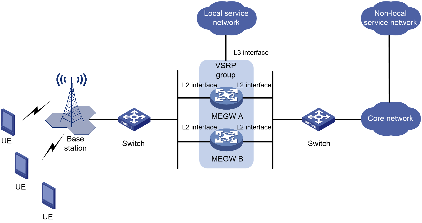
VSRP support for MEC (Layer 2 network)
As shown in Figure 26, MEC operates in a Layer 2 network. The MEGW device uses Layer 2 interfaces to connect separately with the base station and core network, and a Layer 3 interface to connect with the local business network. To enhance the reliability of MEC services, VSRP is deployed on both MEGW A and MEGW B. MEGW A serves as the master device and MEGW B as the backup device. If MEGW A faults, MEGW B takes over and continues to operate, ensuring message forwarding is not disrupted.
VSRP support for MEC (Layer 3 network)
As shown in Figure 27, MEC operates in a Layer 3 network architecture. The MEGW device uses Layer 3 interfaces to connect with the base station, core network, and local business network respectively. To enhance the reliability of MEC service, VSRP is deployed on MEGW A and MEGW B. MEGW A serves as the master device, while MEGW B serves as a backup. When MEGW A experiences a fault, MEGW B takes over its work to ensure the message forwarding will not be disrupted.

