Source Address-Based Slice ID Encapsulation Network SlicingTechnology White Paper-6W100-book.pdf(278.17 KB)
- Released At: 07-04-2025
- Page Views:
- Downloads:
- Table of Contents
- Related Documents
-
Source Address-Based Slice ID Encapsulation Network Slicing
Technology White Paper
Copyright © 2025 New H3C Technologies Co., Ltd. All rights reserved.
No part of this manual may be reproduced or transmitted in any form or by any means without prior written consent of New H3C Technologies Co., Ltd.
Except for the trademarks of New H3C Technologies Co., Ltd., any trademarks that may be mentioned in this document are the property of their respective owners.
This document provides generic technical information, some of which might not be applicable to your products.
Expansion of the control plane
Operating mechanism of the SRv6 BE scenario
Overview of the operating mechanism
Control plane routing learning
Data plane network slicing message forwarding
SRv6 TE policy scenario operating mechanism
Overview of the operating mechanism
Forwarding network slice messages in the data plane
Medical industry private network
Overview
Background
As shown in Figure 1, traditional VPN technology only isolates traffic between services. However, traffic from different VPNs or the public network still shares bandwidth resources during transmission in the IP network. Critical services may experience high latency, jitter, or even packet loss due to insufficient bandwidth resources. Therefore, VPN technology cannot guarantee the differentiated SLA (Service Level Agreement) requirements of different services. To achieve this, the industry has introduced the Enhanced VPN (VPN+) solution, which features service separation, resource exclusivity, and independent management. Network slicing technology is a VPN+ solution. The network slicing technology that encapsulates Slice ID based on the source address applies to SRv6 networking scenarios.
Figure 1 Comparison between traditional VPN technology with VPN+ technology
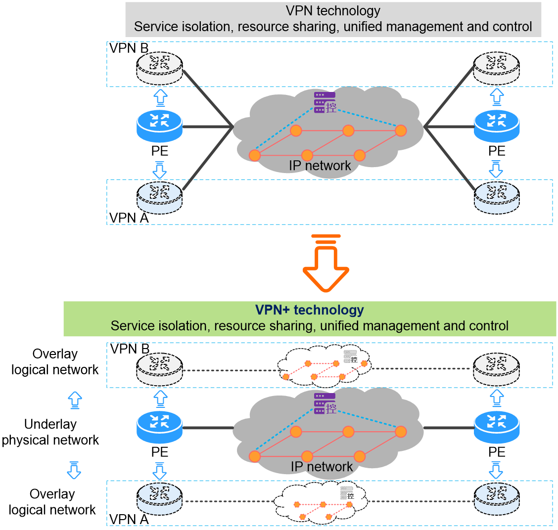
A Slice ID is a globally unique decimal value in a network. Use it to identify virtual logical networks and the physical bandwidth resources they utilize. Each logical network represents a network slice. Encapsulate Slice ID information in the source address of the IPv6 datagram. The device forwards the datagram with the Slice ID through the corresponding logical network, enabling forwarding within a specific network slice. Each physical device allocates dedicated bandwidth resources for the logical network. Therefore, packets carrying the Slice ID can achieve both service separation and resource exclusivity during forwarding.
Technology comparison
Comparing with other network slicing technologies
H3C's existing MDC, subinterface slicing, FlexE, and Flex-Algo flexible algorithms can effectively isolate network resources. Use these technologies for network slicing solutions. The network slicing technology based on source address encapsulation of Slice ID is just one of many network slicing solutions. Compared to other technologies, the network slicing technology based on source address encapsulation of Slice ID offers unique advantages.
· Compared to MDC or Flex-Algo technology, the slice technology based on Slice ID supports a greater number of slices.
¡ Devices use MDC technology to allocate virtualization resources. They support a maximum of 15 MDCs, allowing you to distinguish up to 15 slice networks. Use the Flex-Algo flexible algorithm to calculate up to 128 algorithm topologies, which means you can create 128 independent slice networks.
¡ The slice technology based on Slice ID supports up to a thousand slice networks, fully meeting current business needs.
· Compared to FlexE slicing technology, the Slice ID-based slicing technology offers precise bandwidth control and lower costs.
¡ The bandwidth granularity of FlexE slicing technology is 5 Gbps or 1 Gbps. FlexE-compatible hardware remains relatively expensive and is suitable only for backbone networks or high-bandwidth scenarios.
¡ The bandwidth minimum for each slice network in Slice ID-based network slicing technology can reach 1 Mbps without requiring hardware upgrades or replacements.
· Compared to the Flex-Algo technology for network slicing, the Slice ID-based slicing technology decouples the data plane (DP) from the control plane (CP).
¡ The network slicing solution based on Flex-Algo technology uses the control plane's routing calculations to obtain different network slice topologies. Data forwarding within the network slices relies entirely on the control plane's calculation results. Additionally, administrators need to assign a set of SRv6 Locators for each Flex-Algo algorithm's calculated slice network. This can lead to resource waste of SRv6 Locators due to numerous slice networks. The more topologies the Flex-Algo algorithm calculates, the higher the routing computation complexity in the control plane (CP). Due to the coupling of the data plane (DP) and control plane (CP), the network slicing implemented by Flex-Algo technology is not suitable for large-scale slicing network divisions.
¡ In the Slice ID-based network slicing solution, introduce Slice ID in the data plane's messages and forwarding resources to distinguish different network slices. This approach completely decouples data forwarding from control plane routing calculations. Additionally, different sliced networks can share a set of SRv6 Locators. This approach significantly saves SRv6 Locator resources and reduces the pressure on control plane routing calculations.
Additionally, using network slicing technology based on source address encapsulation Slice ID does not conflict with other network slicing technologies. Different network slicing technologies can work together to offer users flexible and diverse VPN+ solutions.
Comparison of different methods for encapsulating Slice ID
The technology that uses Slice ID to implement network slicing is called Slice ID-based network slicing technology. The current standards and drafts offer various implementations of network slicing technology based on Slice ID. Different vendors may support different standards and implementation methods. The fundamental difference among these implementations lies in the encapsulation position of the Slice ID.
· H3C supports encapsulating Slice ID in the hop-by-hop extension header. This encapsulation scheme requires adding an HBH extension header that carries the Slice ID to the SRv6 packet. This increases redundant information and demands that forwarding devices' hardware support resolving the Slice ID in the HBH extension header, impacting forwarding efficiency.
· H3C also supports encapsulating the Slice ID in the source address of the IPv6 basic header. This encapsulation scheme requires no additional extension headers. The forwarding device's hardware only needs to resolve the source address to obtain the Slice ID information, ensuring efficient forwarding.
· The industry also suggests using the 20-bit Flow Label in the IPv6 header to encapsulate the Slice ID. The Slice ID occupies only part of the Flow Label's bit positions, such as using the top 8 bits. This encapsulation scheme does not affect forwarding efficiency, but it conflicts with the Flow Label definition in RFC8200.
The differences between various Slice ID encapsulation schemes are compared in Table 1.
Table 1 Comparison of Slice ID Encapsulation Schemes
|
Slice ID encapsulation method Difference comparison |
HBH encapsulation Slice ID |
Source address encapsulation Slice ID |
Flow Label encapsulation Slice ID |
|
Length of Slice ID |
Supports a large number of slices with 32-bit architecture. |
Supports a high number of slices in 32-bit. |
Typically, it is only 8 bits and does not exceed 20 bits, with a limited number of supported slices. |
|
Compatibility |
Forward compatibility is not supported; you may need to upgrade your hardware (HW). |
Support backward compatibility; simply upgrade the software version. |
Support forward compatibility; just upgrade the software version. |
|
Forwarding efficiency |
It requires additional overhead, and the hardware resolution speed is slightly slower, which affects forwarding efficiency. |
No additional overhead is needed, and it does not affect forwarding efficiency. |
No additional overhead is required, and it does not affect forwarding efficiency. |
|
Planning requirements |
You can plan anew with minimal difficulty. |
Planning the source address for the existing network is quite challenging. |
You can plan anew with minimal difficulty. |
|
Standard conflict |
N/A |
N/A |
Conflict exists. |
Comparing various encapsulation methods for Slice IDs, using the source address to encapsulate Slice IDs is more challenging in planning, but offers some advantages in other areas.
Technical implementation
Concepts
As shown in Figure 2, the network slice based on the source address encapsulates the following concepts regarding Slice ID:
· Network slice instance (NSI)—An independent virtual network in a network with SRv6 network slicing deployed. A virtual network is identified by its unique NSI ID (also called slice ID). Network slice instances can define the general attributes of the slice, such as the description of the network slice. Only after deploying the network slice instance on the device can the physical device map to the virtual slice network identified by the network slice instance ID.
· Network slice channel—A logical channel on an interface, used for forwarding network slice packets. The network slicing channel identifies and associates network slicing instances through the Slice ID. You can create multiple network slice channels on an interface and assign an independent scheduling queue to each network slice channel. In this way, the scheduling queues for network slice channels do not affect each other. Allocate dedicated bandwidth resources and achieve resource isolation by dividing network slices on the interface.
· Network slice packets—IPv6 packets transmitted within a network slice instance. The IPv6 header of these packets carries the Slice ID, which identifies the associated network slice instance. Network slice packets with the Slice ID will be forwarded through the network slice channel identified by the Slice ID.
Figure 2 Network slicing diagram based on source address encapsulation Slice ID

Expansion of the data plane
The message structure encapsulates the Slice ID based on the source address, as shown in Figure 3. For more information about the details in the IPv6 message source address, see Figure 4.
Figure 3 Message structure encapsulates Slice ID based on the source address.

Figure 4 Illustration of the detailed composition of the IPv6 source address with Slice ID
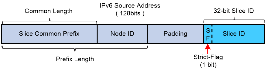
The IPv6 source address carrying Slice ID information includes the following components:
· Slice Common Prefix: Also known as SPI (Slice ID Presence Indicator) in IETF drafts, this feature identifies whether the IPv6 source address carries Slice ID information. It is dedicated to slicing and occupies the highest bits of the IPv6 source address. Users can specify the length of the Slice Common Prefix. Typically, all devices in the same SRv6 slicing network use the same slice common prefix.
· Node ID: Use this to identify different devices within the same regional network. The slice common prefix and Node ID together form the IPv6 source address prefix carrying the Slice ID. You can use IS-IS to advertise the IPv6 source address prefix containing the Slice ID to other devices within the domain. Use this IPv6 source address prefix for routing between devices and create a directly connected route entry for the IPv6 source address prefix in the local device's FIB table.
· NSI ID (slice ID)—Least significant 32 bits of the IPv6 source address. The first bit is the Strict-Flag flag bit. If this flag bit is set to 1 in a network slice packet, the device must forward the packet through a network slice channel bound to the NSI ID. If no network slice channels are bound to the NSI ID, the device discards the packet. If this flag bit is set to 0 in a network slice packet, the device searches for a network slice channel bound to the NSI ID to forward the packet. If no network slice channels are bound to the NSI ID, the device does not discard the packet. Instead, it forwards the packet according to the SRv6 packet forwarding process. Since the first bit of the Slice ID serves as the Strict-Flag flag bit, the maximum length of the Slice ID for configuring and distinguishing different network slice instances is 31 bits.
· Padding—If the total length of the slice common prefix, node ID, and NSI ID is less than 128 bits, fill with 0s after the IPv6 source address prefix to make up for it.
Expansion of the control plane
BGP IPv6 SR policy expansion
After establishing the BGP IPv6 SR Policy peer between the controller and forwarding device, the controller publishes the BGP IPv6 SR Policy routes to the forwarding device to create the SRv6 TE Policy. Therefore, in the control plane, the BGP IPv6 SR Policy routing NLRI needs expansion to support Sub-TLVs that carry Slice ID information. Comware follows the draft-dong-idr-sr-policy-vtn-01 proposal and uses the VTN (Virtual Transport Network) Sub-TLV defined in this draft to carry Slice ID information. Therefore, it can also be called Slice ID Sub-TLV.
Currently, Comware carries the Slice ID Sub-TLV in BGP IPv6 SR Policy routing by adding the Slice ID Sub-TLV in the Tunnel Encaps Attribute. The format example is as follows:
SRv6 TE Policy SAFI NLRI: <Distinguisher, Policy Color, Endpoint>
Attributes:
Tunnel Encaps Attribute (23)
Tunnel Type: SRv6 TE Policy
Binding SID
Preference
Priority
Policy Name
Policy Candidate Path Name
Slice ID
Segment List
Weight
Segment
Segment
...
The format of the Slice ID Sub-TLV appears as shown in Figure 5.

The fields included in the Slice ID Sub-TLV are shown in Table 2.
Table 2 Slice ID Sub-TLV field description table
|
Item |
Length |
Description |
|
Type |
8-Bit |
Sub-TLV type, with a value of 123. |
|
Length |
8-Bit |
Flags and Slice ID lengths in Sub-TLV |
|
Flags |
8-Bit |
Flag bit, reservation for future use. |
|
Reserved |
8-Bit |
Reservation, set the value to all zeros. |
|
Slice ID |
32-Bit |
Slice ID value |
BGP-LS expansion
Devices can report the SRv6 TE Policy configuration and status to the controller (CTL) using BGP-LS. Therefore, the Link-State NLRI reporting SRv6 TE Policy information must support the Slice ID TLV. The message format of the Slice ID TLV is shown in Figure 6.

The Slice ID TLV includes fields as shown in Table 3.
Table 3 Field description table for Slice ID TLV
|
Item |
Length |
Description |
|
Type |
16-Bit |
The TLV type value is pending application. |
|
Length |
16-Bit |
Set the length of the Value section to 4. |
|
Slice ID |
32-Bit |
Slice ID value |
Operating mechanism of the SRv6 BE scenario
Overview of the operating mechanism
In SRv6 BE scenarios, use the Slice ID-based network slicing solution for IP L3VPN over SRv6 BE, EVPN L3VPN over SRv6 BE, public IP over SRv6 BE, EVPN VPLS over SRv6 BE, and EVPN VPWS over SRv6 BE.
To forward traffic in a network slice identified by Slice ID, the local PE device needs to learn BGP routes with Color extended community attributes from the remote PE. Associate the Color extended community attribute of the BGP route with the Slice ID and the IPv6 source address prefix that carries the Slice ID. When the destination address in the datagram matches the corresponding BGP route entry, the system can forward the traffic through the network slice identified by Slice ID. Therefore, in the SRv6 BE scenario, implement the Slice ID-based network slicing solution by first completing BGP route learning in the control plane. This article uses IP L3VPN over SRv6 BE for message forwarding to illustrate the working mechanism of Slice ID-based network slicing.
Control plane routing learning
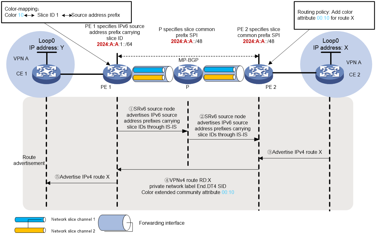
As shown in Figure 7, the SRv6 network includes network slice instance 1 and network slice instance 2. PE 1 and PE 2 each have forwarding interfaces associated with network slice instance 1 and network slice instance 2, respectively, linked to channel 1 and channel 2.
Traffic between two sites, CE 1 and CE 2, in VPN A forwards using the SRv6 BE method.
The preparation (Prep) tasks are as follows:
· To enable SRv6 source node PE 1 to encapsulate the IPv6 source address with Slice ID into network slice packets, specify the IPv6 source address prefix with Slice ID on PE 1 and advertise this prefix to IS-IS. In this example, the IPv6 source address prefix for PE 1 is 2024:A:A:1::/64, with the shared prefix SPI being 2024:A:A::/48. Simultaneously specify the relationship between the Color attribute, Slice ID, and the IPv6 source address prefix.
· To enable forwarding nodes in the SRv6 network to identify Slice ID information from the source address of network slice packets, specify the Slice ID carrying public prefix SPI or the IPv6 source address prefix on the P device. In this example, all nodes in the SRv6 network share a common slice prefix SPI 2024:A:A::/48.
The process of publishing the private network route from CE 2 to CE 1 is as follows:
Use IGP or BGP to publish the private network route X from the Loopback 0 interface of this site to PE 2.
Upon learning the route, PE 2 adds the route to the routing table of VPN instance A. PE 2 adds RD and RT attributes to the private network route, and assigns an End.DT4 SID to the private network route, creating a VPNv4 route RD:X. PE 2 adds the Color extended community attribute with an attribute value of 00:10 to the VPNv4 route RD:X through the routing policy. Then, it publishes the VPNv4 route carrying the Color extended community attribute to PE 1 via MP-BGP.
PE 1 receives the VPNv4 route, adds it to the routing table of VPN1, and records its Color extended community attribute as 00:10. On PE 1, associate Color attribute 10 with network slice Slice ID 1 and the IPv6 source address prefix 2024:A:A:1::/64 that carries the Slice ID.
PE 1 converts the VPNv4 route RD:X to an IPv4 route, and advertises the route to CE 1.
Upon receiving the route, CE 1 learns it to its routing table.
Figure 7 Diagram for route learning in IP L3VPN over SRv6 control plane
Data plane network slicing message forwarding
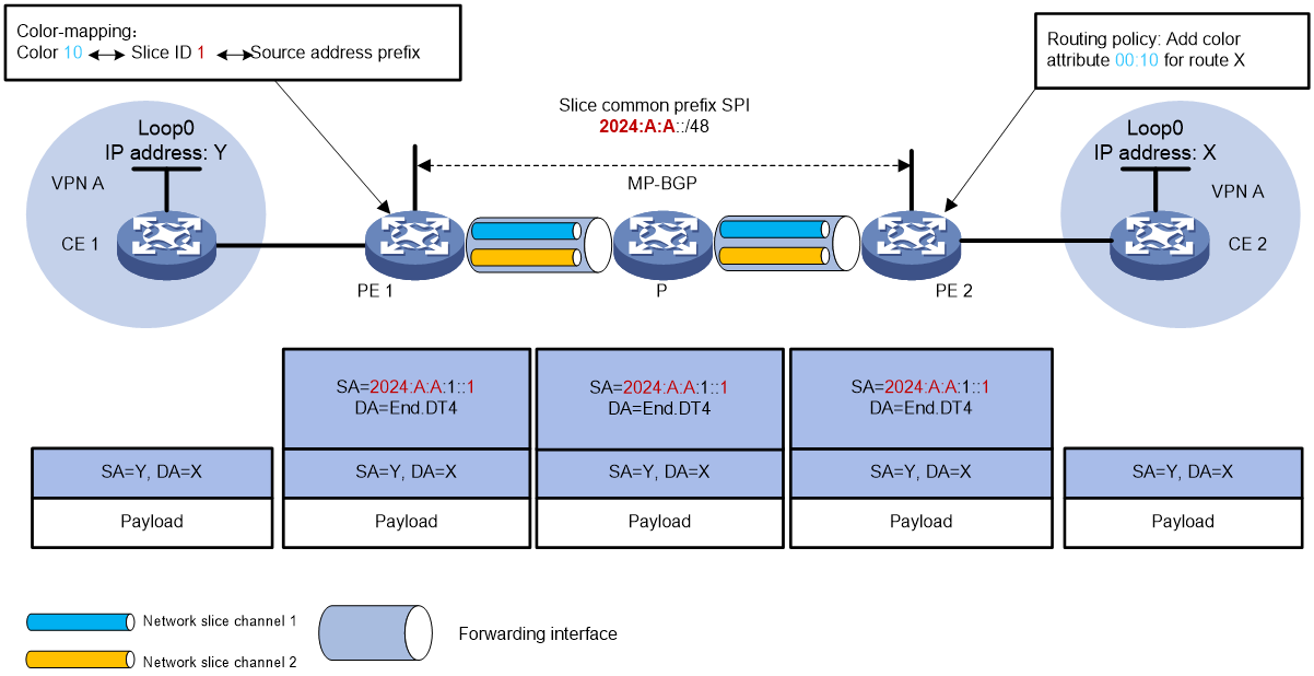
As shown in Figure 8, the forwarding process of private network packets from CE 1 to CE 2 is as follows:
CE 1 sends an IPv4 packet with destination address X to PE 1.
After PE 1 receives a private network message from the interface bound to VPN A, it searches the routing table of VPN-instance A for a matching route X. It finds the corresponding End.DT4 SID and notices that the Color extended community attribute 00:10 maps with Slice ID 1 and the IPv6 source address prefix 2024:A:A:1::/64. Based on the configured slicing encapsulation method, PE 1 encapsulates the IPv6 message header, modifying the source address to IPv6 Prefix + Padding (all zeros) + Slice ID. As a result, the source address of the network slicing message becomes 2024:A:A:1::1, and this message needs to be forwarded through the Slice ID 1 network slice.
PE 1 looks up the IPv6 FIB table based on End.DT4, with its outgoing interface being the interface between PE 1 and P. PE 1 compares the source address in the IPv6 packet header with the locally configured slice common prefix 2024:A:A::. If they match, forward the packet through the network slice channel indicated by the source address. PE 1 retrieves the Slice ID value from the lower 32 bits of the source address. It then looks up the corresponding network slice channel on the outgoing interface and forwards the packets through that channel. PE 1 forwards the message to P.
Use End.DT4 to find the IPv6 FIB table. Repeat the process in step 3 to forward the packet to PE 2 using the optimal IGP route.
After PE 2 receives the packet with the destination IPv6 address of End.DT4 SID, it performs decapsulation to remove the IPv6 header. Then, it matches the End.DT4 SID to VPN A, looks up the routing table for VPN A, and sends the packet to CE 2.
Figure 8 Forwarding process of IPv4 L3VPN over SRv6 BE scenario network slicing packets.
SRv6 TE policy scenario operating mechanism
Overview of the operating mechanism
The candidate paths for the SRv6 TE Policy need to associate with the Slice ID and the IPv6 source address prefix that carries the Slice ID. When the source node redirects traffic to the SRv6 TE Policy, the device uses the Slice ID associated with the SRv6 TE Policy candidate path to import traffic into the corresponding slice network for forwarding. In the SRv6 TE Policy scenario, implement the network slicing solution based on Slice ID without establishing mappings between the BGP route's Color extended community attribute and Slice ID. Simply redirect traffic to the SRv6 TE Policy. Therefore, in the SRv6 TE Policy scenario, the network slicing solution that encapsulates the Slice ID based on the source address does not require adjustments to the control plane routing learning process. This document uses the example of packet forwarding in the IP L3VPN over SRv6 TE Policy scenario to explain the working mechanism of network slicing based on Slice ID.
Forwarding network slice messages in the data plane
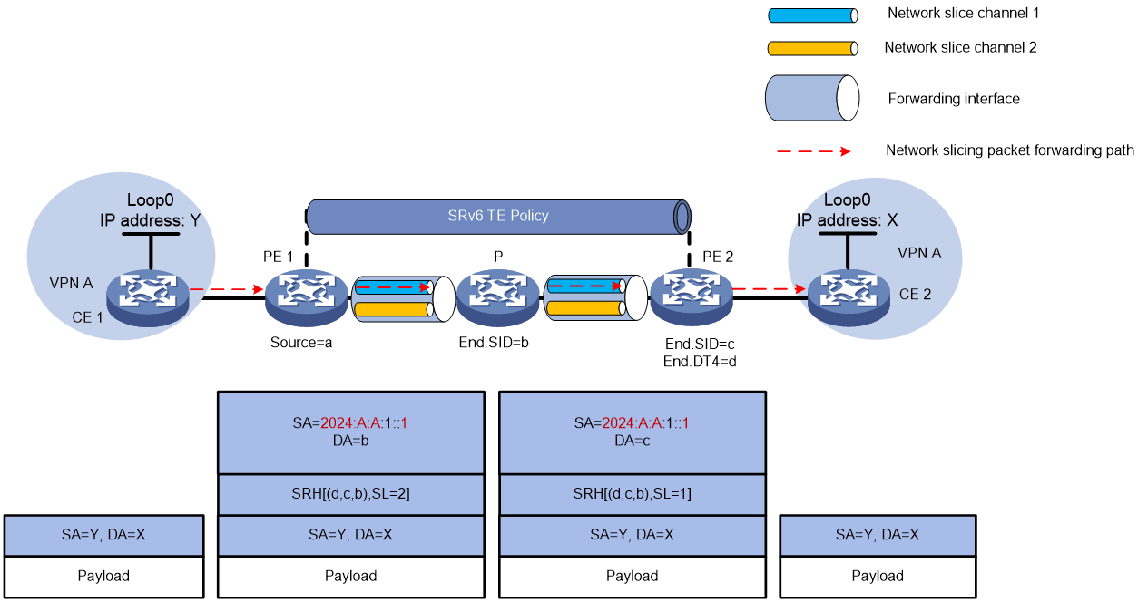
As shown in Figure 9, the SRv6 network includes network slice instance 1 and network slice instance 2. PE 1 and PE 2 both have forwarding interfaces associated with network slice instance 1 and network slice instance 2, linked to channel 1 and channel 2, respectively. Traffic between CE 1 and CE 2 in VPN A is forwarded through the SRv6 TE Policy tunnel.
The preparation (Prep) steps for configuration are as follows:
· To enable the SRv6 source node PE 1 to encapsulate the IPv6 source address with Slice ID into network slice packets, specify the IPv6 source address prefix with Slice ID on PE 1 and publish this prefix to IS-IS. In this example, the IPv6 source address prefix for PE 1 is 2024:A:A:1::/64, with the slice public prefix SPI as 2024:A:A::/48. At the same time, specify the forwarding path and Slice ID under the candidate path of the SRv6 TE Policy, along with the association of the IPv6 source address prefix carrying the Slice ID.
· To enable forwarding nodes in the SRv6 network to identify Slice ID information from the source address of network slice packets, specify the Slice Public Prefix SPI or the IPv6 source address prefix carrying the Slice ID on the P device. In this example, all nodes in the SRv6 network share a unified slice public prefix of SPI 2024:A:A::/48.
The message forwarding process from CE 1 to CE 2 is as follows:
CE 1 sends IPv4 unicast packets to PE 1. After PE 1 receives the packets sent by CE 1, it looks up the routing table of VPN instance A and detects that the output interface for the matching route is the SRv6 TE policy. PE 1 encapsulates the Slice ID using source address slicing based on the configuration.
¡ The SRH header that contains the SID list of the SRv6 TE policy.
¡ Encapsulate the basic IPv6 packet header. Modify the source address in the IPv6 header to IPv6 Prefix + Padding (all 0s) + Slice ID. In this example, PE 1 configures the IPv6 Prefix as 2024:A:A:1:: with a length of 64 and a Slice ID of 1. Therefore, the source address becomes 2024:A:A:1::1. This packet needs to be forwarded through the Slice ID 1 network.
PE 1 looks up the IPv6 FIB table based on the destination address, using the interface between PE 1 and P as its outgoing interface. PE 1 compares the source address in the IPv6 packet header with the locally configured slice common prefix 2024:A:A::. This indicates that the packet needs to be forwarded through the network slice channel based on the source address. PE 1 retrieves the Slice ID value from the low 32 bits of the source address. It then looks up the corresponding network slice channel on the outgoing interface and forwards the packet to P through this channel.
Repeat the processing steps in the intermediate device as described in step 2. During forwarding, use the Slice ID to find the corresponding network slice channel on the outgoing interface, and forward the packet through that channel.
After the packet reaches the tail node PE 2, use the packet's IPv6 destination address to look up the Local SID table. PE 2 matches it to the End SID, decreases the packet's SL by 1, and updates the IPv6 destination address to End.DT4 SID. PE 2 looks up the Local SID table using the End.DT4 SID. It executes the forwarding action corresponding to the End.DT4 SID by decapsulating the packet and removing the IPv6 header. Then, it matches the End.DT4 SID with VPN A, checks the routing table, and forwards the packet to CE 2.
Figure 9 Forwarding process of IPv4 L3VPN over SRv6 TE Policy in network slicing
IPv6 source address planning
Principles for planning the source address
In the network slicing technology based on source address encapsulation of Slice ID, the administrator must plan the IPv6 packet source address effectively to meet the following requirements:
· Maintain consistency within the domain: The Slice ID in the source address of IPv6 packets carries a common prefix SPI that remains the same across the autonomous domain. All devices within the domain can identify the Slice ID from the uniform SPI in the source address. If business spans multiple domains, the ASBR between domains supports re-encapsulation of the source address in the outer header. Therefore, different autonomous domains can have varying slice public prefix SPIs.
· Avoid overlap with business and interface addresses: the shared prefix SPI must not be the same as or overlap with any business addresses or interconnection interface addresses. If a certain type of business address prefix matches the slice common prefix SPI, it may cause messages sourced from that address to be incorrectly forwarded through the slice network. If a loopback address prefix matches the slice's common prefix SPI and serves as the source address for SRv6 VPN encapsulation, these packets will incorrectly forward through the slice network.
Example of source address planning
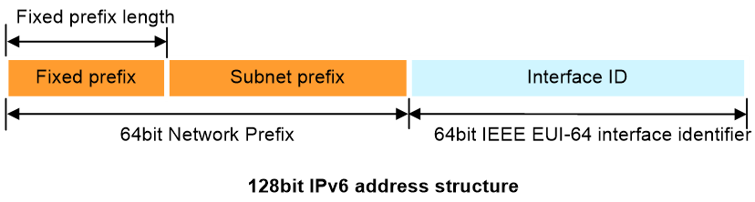
As shown in Figure 10, the IPv6 Global Unicast Address (GUA) consists of two parts: the network prefix and the interface ID.
· The Interface ID follows the IEEE EUI-64 format and occupies the lower 64 bits of the 128-bit IPv6 address. Use it to uniquely identify an interface within a subnet. The SLAAC (Stateless Address Autoconfiguration) mechanism in IPv6 uses the EUI-64 format to automatically generate the Interface ID. Therefore, do not corrupt the complete 64-bit Interface ID structure. Use the Interface ID portion for subnet division.
· The network prefix occupies the high 64 bits of the 128-bit IPv6 address, allowing for subnetting within this range. The IPv6 GUA address network prefix consists of a fixed prefix and a subnet prefix. The fixed prefix is a designated address block obtained from regional network information centers and cannot be changed.
Figure 10 128-bit IPv6 GUA address structure
The IPv6 source address structure with Slice ID includes four parts: SPI prefix, Node ID, Padding, and Slice ID. The slice public prefix SPI and different Node IDs distinguish various SRv6 source nodes within the domain, forming part of the network prefix. To avoid wasting address space, the Padding section does not occupy the high 64 bits of the network prefix, using only the SPI and Node ID as the network prefix. Therefore, SPI and Node ID can occupy the highest 64 bits of an IPv6 GUA address. Reserve the length of the Node ID based on the number of SRv6 nodes in the domain and future expansion needs. This prevents insufficient space for the Node ID, ensuring you can allocate addresses to all SRv6 nodes. Additionally, Padding and Slice ID occupy the lower 64 bits. The Slice ID occupies a minimum of 32 bits, allowing for a sufficient number of identifiable network slices. Typically, a single slice common prefix SPI or a few common prefixes SPI meet the domain's needs.
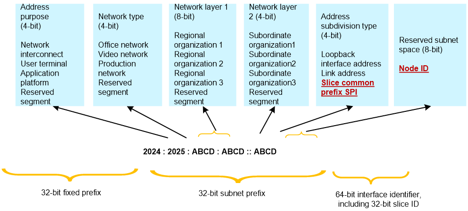
For example, as shown in Figure 11, a large organization applied to the Asia-Pacific Internet Information Center for a fixed prefix length of 32 bits, receiving the IPv6 address block 2024:2025::/32. Divide the 64-bit network prefix into the following sections to meet the network design requirements:
· The maximum 32-bit address space has a fixed prefix that cannot be changed. You can only further divide the remaining 32 bits of address space.
· Classify all addresses based on purpose and network type according to unified planning principles. Reserve up to 4 bits to distinguish address purposes, such as user addresses, application platform addresses, and internetworking addresses. Use a 4-bit space to differentiate network types, such as office networks, video networks, and production networks.
· Reserve address space for the regional center (level one) and its subordinate institutions (level two) according to hierarchical address planning principles. Plan the necessary address space bits based on the number of regional centers and subordinate institutions at each level. In this case, the regional center may exceed 100 in the future, while subordinate institutions will not exceed 10. Reserve 8 bits of address space to distinguish the regional center (level one) and 4 bits to distinguish subordinate institutions (level two).
· Further subdivide addresses and reserve subnet space for subordinate organizations. Choose a value within the 4 bits of address type as the slice public prefix (SPI) with a length of 56 bits. Use the 8 bits of subnet space as the Node ID.
· The lower 32 bits of the 64-bit interface identifier represent the Slice ID.
Figure 11 Example of hierarchical IPv6 address planning for a large organization
|
|
NOTE: When planning IPv6 address allocation, use a 4-bit address space as the smallest unit for address division, since IPv6 addresses are configured and managed using hexadecimal numbers. Do not corrupt the structure of the 4-bit minimum unit, or it may complicate the configured address filtering rules and policies |
Typical applications
Medical industry private network
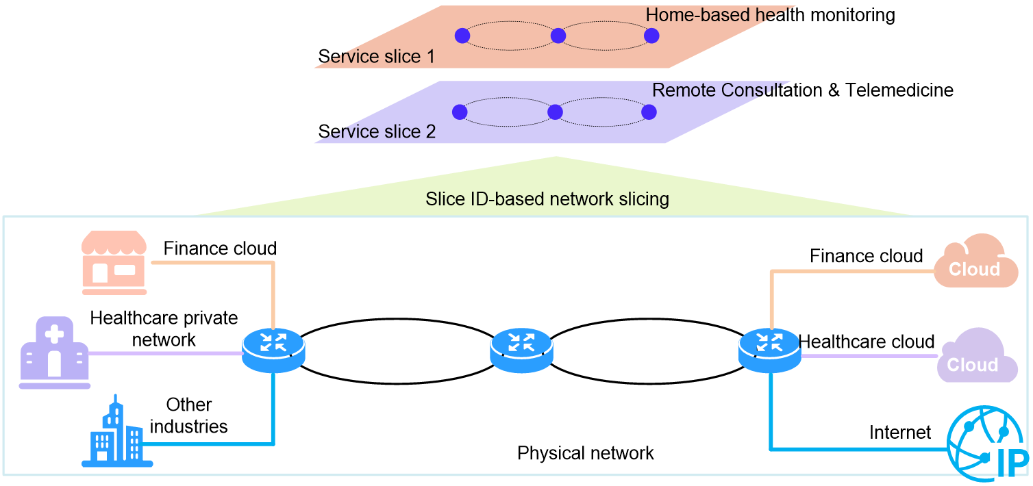
Urban and rural hospitals aim to leverage ICT technology to advance smart healthcare and provide professional medical services to more people. The smart healthcare system includes services such as disease prevention, home medical monitoring, health consulting, remote consultations, remote surgical training, and international communication. Therefore, the smart healthcare system needs to establish a dedicated network connecting patients, urban and rural hospitals, and various medical research and teaching institutions. Additionally, create comprehensive cloud services for the healthcare industry.
The medical industry's private network requires seamless business channels between healthcare institutions. Share system data resources, enhance business bandwidth, and ensure ultra-low transmission delays to meet special real-time needs.
In the carrier transport network shown in Figure 12, use Flex-Algo technology to customize network topology for the healthcare industry. Implement network slicing based on source address encapsulation Slice ID to create business slices for home medical monitoring and remote consultation services. Provide different quality assurance (QA) based on the SLA requirements for each service.
· Medical monitoring service—The network slice with slice ID 1 provides the remote control service. This network slice uses FlexE logical interfaces to forward data packets. The latency is stable and low. In addition, TI-LFA FRR is deployed to ensure high availability.
· Remote consultation service—Use slice ID 2 to identify the slice network. This network forwards datagrams via a 1Gbps bandwidth subinterface, supporting high-definition video calls.
References
draft-cheng-spring-srv6-encoding-network-sliceid
draft-filsfils-spring-srv6-stateless-slice-id
draft-dong-idr-sr-policy-vtn
