- Released At: 12-05-2025
- Page Views:
- Downloads:
- Table of Contents
- Related Documents
-
Loop Detection and Prevention Technology White Paper
Copyright © 2024 New H3C Technologies Co., Ltd. All rights reserved.
No part of this manual may be reproduced or transmitted in any form or by any means without prior written consent of New H3C Technologies Co., Ltd.
Except for the trademarks of New H3C Technologies Co., Ltd., any trademarks that may be mentioned in this document are the property of their respective owners.
This document provides generic technical information, some of which might not be applicable to your products.
Contents
Introduction to various loop protection technologies
Introduction to loop detection
Summary and comparison of loop protection technologies
Loop prevention technologies in data center networks
Loop prevention technologies in campus network
Overview
Network administrators typically deploy multiple links at crucial points in the network to enhance its reliability. However, this deployment method can easily create level-two loops, leading to network resource wastage, sharp bandwidth decline, or even network unavailability. Our devices can use several technical methods to detect, prevent, and eliminate level-two loops, such as STP, RRPP, ERPS, loop detection, etc. These techniques can effectively prevent a broadcast storm.
Firstly, this article will categorize and compare our company's various class two loop protection protocols based on their technical features and application scenarios, to help users better utilize these protocols. For the detailed principles and mechanisms of the related protocols, please refer to the Technology White Paper of the protocol.
In the conclusion of this article, we will conduct a practical application analysis using the network group from several classic solutions proposed by our company as a case study. We will discuss the occurrence of second stratum loops in each network group and the applicable loop prevention protocol.
Introduction to various loop protection technologies
Introduction to Spanning Tree
The Spanning Tree Protocol selectively blocks redundant links in the network to eliminate Layer 2 loops. Our company's Spanning Tree functionalities include four types of Spanning Tree Protocols: STP (Spanning Tree Protocol), RSTP (Rapid Spanning Tree Protocol), PVST (Per-VLAN Spanning Tree), and MSTP (Multiple Spanning Tree Protocol). All four types of Spanning Tree Protocols can eliminate Layer 2 loops, each offeloop different functions.
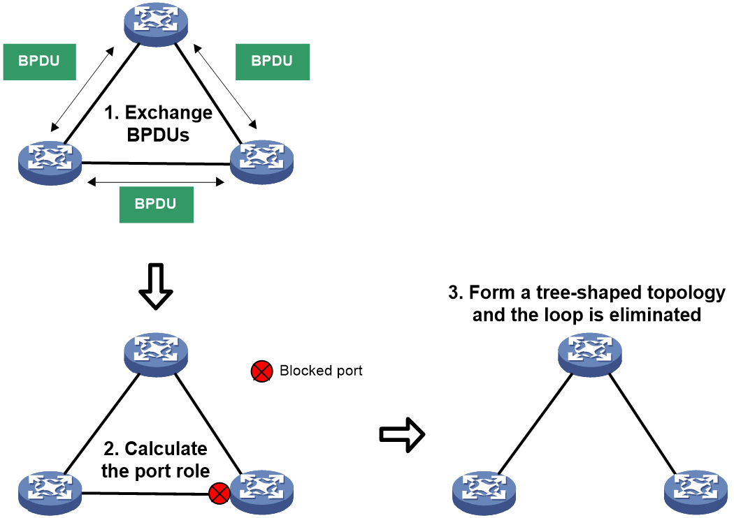
· STP: Defined by the IEEE 802.1D standard. Devices running this protocol interact with each other to discover loops in the network, and selectively block certain ports, eventually trimming the loop network structure into a loop-free tree network structure. This prevents the constant increase and infinite looping of packets in the loop network, avoids the device receiving the same packets repeatedly, and prevents a decline in packet processing ability.
· RSTP, defined by the IEEE 802.1w standard, improves upon STP for fast convergence of network topology. In STP, the newly elected root port and designated port need to go through twice the state migration delay time before enteloop the forwarding state. However, RSTP is faster; when a port is selected as the root port and designated port and meets certain conditions, the port can quickly transition to the forwarding state without waiting, thereby reducing the time needed for the network to reach a stable topology.
· PVST: In LAN, STP and RSTP share a spanning tree across all VLANs, and redundant links can't be blocked per VLAN, with all VLAN's messages being forwarded along the same spanning tree. However, PVST can calculate a separate spanning tree for each VLAN, effectively improving link bandwidth utilization. PVST can be simply understood as running a RSTP protocol on each VLAN, with the spanning trees between different VLANs being completely independent. By calculating different tree-like topologies for different VLANs, traffic from different VLANs can be forwarded along different paths for the shaloop of business data load.
· MSTP, defined by the IEEE 802.1s standard, partitions a switched network into multiple regions, with each region independently forming multiple spanning trees. Each region separates different trees by setting the relationship between VLANs and spanning trees. Unlike PVST, which calculates a separate spanning tree for each VLAN and puts a high load on the system when there are many VLANs, MSTP can enable multiple VLANs to share a single tree, OR a single VLAN to calculate a separate tree, providing a more flexible configuration. By calculating different tree-like topologies for different VLANs, traffic from different VLANs can be forwarded along different paths, enabling load shaloop of business data.
Figure 1 Spanning Tree Working Mechanism Diagram
Introduction to loop detection
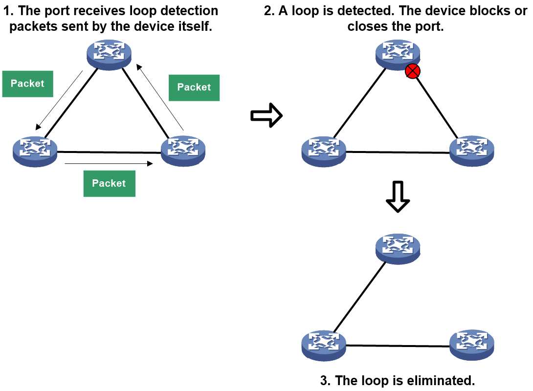
The loop detection function periodically transmits specific messages for identifying loops. If a port on a device receives a loop detection message sent by the device itself, it is determined that there is a loop in the link where the port is located. When a loop is detected, the loop detection function can generate a log info to notify the user and take measures (such as blocking or closing the port) against the port where the loop appears, based on the preset configuration. After the loop disappears, the loop detection function can automatically restore the blocked or closed port to the normal transmission state.
Figure 2 Schematic Diagram of Loop Detection Working Mechanism
Introduction to RRPP
In industrial-level application scenarios, high stability of the topology is required. The convergence speed of the Spanning Tree Protocol (STP) in large networks is slow and cannot meet these requirements. Our company's proprietary protocol, Rapid Loop Protection Protocol (RRPP), is an Ethernet anti-loop link layer protocol, independent of network diameter convergence time. It can achieve a convergence speed within 50ms, showing a clear advantage over STP in networks with larger diameters.
RRPP also has the following features:
· When the Ethernet loop is intact, it can prevent broadcast storms caused by data loops. If a link on the Ethernet loop disconnects, it can quickly enable the backup link for the restoration of communication links between each node on the loop network.
· In intersecting loop topology, each loop is calculated independently. A change in one loop topology will not cause topology oscillations in other loops, ensuloop stable data transmission.
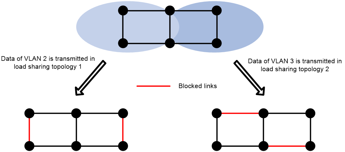
· You can implement load shaloop by configuloop multiple RRPP domains, allowing traffic from different VLANs to be passed along different paths in the loop network.
Figure 3 Schematic Diagram of RRPP & ERPS Working Mechanism
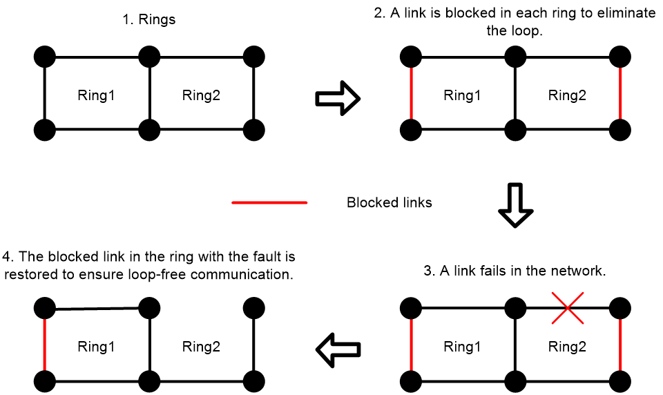
Figure 4 RRPP & ERPS Load Sharing Diagram
Introduction to ERPS
The anti-loop concept and loop avoidance mechanism of ERPS (Ethernet Loop Protection Switching) are similar to RRPP. For more information, please refer to "Section 2.3" and "RRPP Overview".
The distinction between ERPS and RRPP lies in:
· ERPS is a standard protocol defined by ITU-T that is compatible with devices from other manufacturers.
· RRPP is an H3C-proprietary protocol (CPP) and cannot be compatible with devices that do not support the RRPP protocol.
Introduction to Smart Link
Smart Link is specifically designed for implementing redundancy backup of primary and standby links in dual-upstream group networking. Smart Link has the following features:
· To achieve the rapid switchover between the main and standby link, the switchover time can be less than 1 second.
· Smart Link allows load sharing loop by enabling different VLAN traffic to be forwarded along different paths of Smart Link group through the setting of multiple Smart Link groups.
As shown in Figure 5, Device C and Device D connect to upstream devices through dual uplinks. Without using Smart Link, data is passed through the upstream ports of both Device C and Device D, creating a loop between Device C, Device B, Device A, and Device E (the same applies to Device D). After adopting Smart Link, the two upstream interfaces of Device C and Device D join the Smart Link group. Normally, only one of the two upstream ports on Device C and Device D is in a forwarding state, while the other is blocked and in standby mode, eliminating the loop.
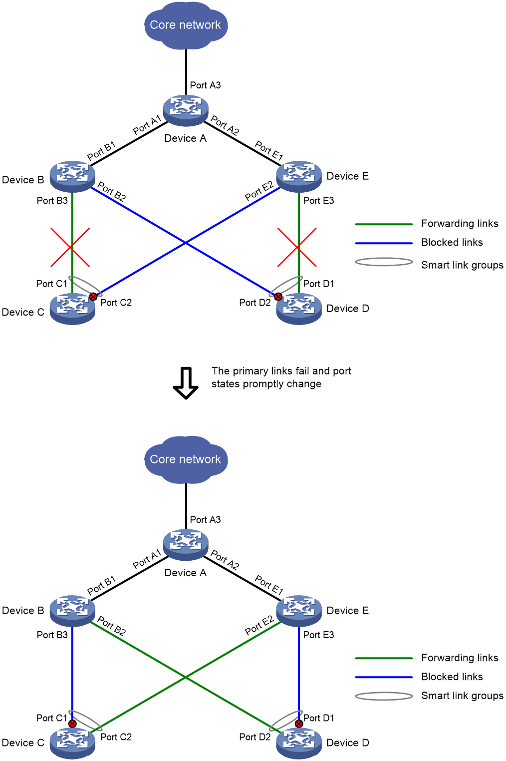
When a port in forwarding state experiences a link fault, Smart Link will quickly switchover the standby port to forwarding state, and block the port with the link fault, achieving link switchover in forwarding state, as shown in Figure 6.
Figure 5 Smart Link Network Diagram
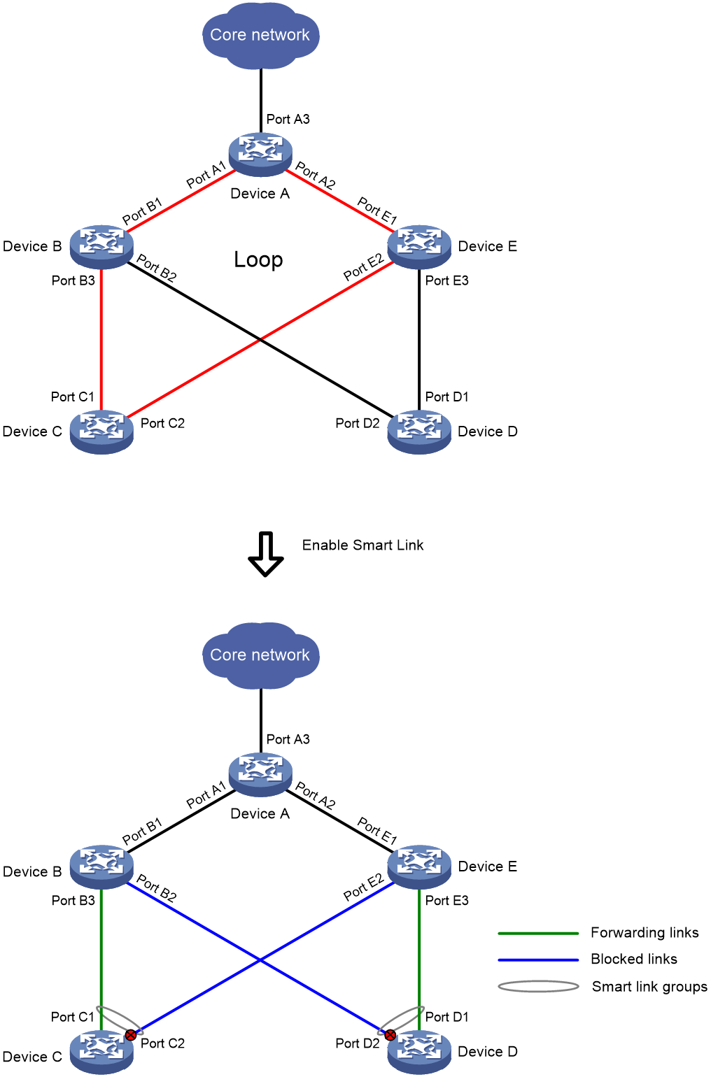
Figure 6 Smart Link link switchover schematic diagram
Summary and comparison of loop protection technologies
The technical advantages, applicable scenarios, and application limitations of the above-mentioned loop protection technology are shown in Table 1.
Table 1 Loop-Technical Summary and Classification Table
|
Protocol Type |
Technical Advantage |
Applicable scenario. |
Restrictions and guidelines |
|
Spanning tree |
· The Spanning Tree is a standard protocol of IEEE characterized by its good compatibility. · The spanning tree supports any physical topology, without the model limitations of a loop network topology. |
· In scenarios where the network radius is small and grouping networks is relatively simple. · Multi-vendor interoperability scenario. |
· After the physical topology changes, the convergence time is relatively long (measured in seconds), and the convergence time will increase as the network radius expands. · Only PVST and MSTP can achieve load shaloop, however, the configuration is relatively complex. |
|
RRPP |
· The topology converges quickly, with a convergence time of less than 50ms. · The convergence time is independent of the network diameter, making it suitable for large-scale networks. · A change in the topology of one loop will not affect the topology of other loops, ensuloop stable data transmission. |
· In industrial-level scenarios with a large network radius and high convergence performance requirements, use the preferred bilingual terms. · Purely our company's device scenario. |
· The types of network configurations supported are relatively fixed. · The configuration is rather complex. · The scalability is poor. When expanding the network, it can easily cause stream interruption or loop formation. · The compatibility is poor and it cannot communicate with devices that do not support RRPP. |
|
ERPS |
· The topology converges quickly, with a convergence time that can be less than 50ms. · Convergence time is independent of network diameter, making it applicable to large-scale networks. · A change in the topology of one loop won't affect the topology of other loops, which results in a more stable data transmission. · EPRS is a standard protocol that can communicate with devices from other manufacturers. |
· In industrial-level scenarios where the network radius is large and there is a high requirement for convergence performance. · Interoperability scenario among multiple manufacturers. |
· The types of network topology supported are relatively fixed. · The configuration is quite complex. · With poor expandability, it's easy to cause stream interruptions or loop formation when expanding the network. |
|
Smart Link |
· The switchover speed between the primary and standby links is fast, and can be less than 1 second. · The configuration is simple. · Load sharing loop is easy to implement and can fully utilize the upstream bandwidth. |
· In a scenario with redundant backup dual uplink connections, a rapid switchover between the primary and secondary links is required. |
· Can only be used for dual upstream group networking. · Without a detection mechanism, when a fault occurs in the transmission equipment or transmission link of the upstream link, it is unable to detect these faults and execute a switchover independently. It requires the cooperation of other function's detection mechanisms to complete the link switchover. |
|
Loop detection |
It supports various loop processing methods, including port blocking, link disconnection, and prohibiting MAC address learning, etc. |
· In VXLAN networking, scenarios where the site's second stratum network forms a loop with the VXLAN network, or scenarios where a loop exists within the site. · In the networking of MPLS L2VPN and VPLS, scenarios where site Layer-2 network forms a loop with MPLS L2VPN network or VPLS network, or scenarios where there exist loops within the site, occur. · A simple two-stratum loop scenario in network setup. |
· The loop detection function cannot be used simultaneously with other stratum 2 loop prevention protocols. · Enabling loop detection for multiple VLANs will increase the burden on the system. · The loop detection function needs to first detect the loop before it can eliminate it. There is a time interval in between, making rapid loop elimination impossible. |
Loop prevention technologies in data center networks
Typical application scenarios
Figure 7 shows a common Spine-Leaf data center network schema, in which users within the data center are connected via VXLAN or VLAN networks for communication. To avoid single point failures, two Border devices connecting to the external network, as well as two Spine devices within the data center, are set up and deployed along with two ED devices interconnected with other data centers using VXLAN-DCI tunnels. In this network, loop issues are highly likely to occur due to the complex local site connections of Leaf devices.
Figure 7 Data center network diagram

Introduction to loop point
Loop point one
Loop point description
CE 1 and CE 2, which connect different Leaf devices, cannot only communicate via VXLAN or VLAN network through Leaf device, but also through a directly connected Layer 2 network. The loop formed between the VXLAN or VLAN network and Layer 2 network can easily cause a broadcast storm.
Loop Prevention Technology
After enabling the loop detection function on Leaf 1 and Leaf 2:
· In the VXLAN network, Leaf 1 or Leaf 2 automatically disables MAC address learning for the AC that has a loop, and blocks it to eliminate the loop.
· In the VLAN network, either Leaf 1 or Leaf 2 can disable or block the ports detected to create a loop, or prevent the ports from MAC address learning to eliminate the loop.
Loop point two
Loop point description
Inside the site connected to Leaf 3, CE 3, CE 4, and CE 5 are interconnected in pairs within the stratum two network, forming a loop, thereby causing a broadcast storm. Risks such as out of service may occur when CE 3, CE 4, and CE 5 are interconnected.
Loop Prevention Technology
The following loop prevention technical methods can be used to eliminate loops within the Leaf 3 site:
· On CE 3, CE 4, and CE 5, the Spanning Tree Protocol (STP) is enabled, which can identify loops and automatically calculate the blocked ports. The loops are eliminated by blocking these ports.
· Start the loop detection function on either CE 3, CE 4, or CE 5 device. The function will automatically detect the ports with loops and block or shut them down to eliminate the loop.
Loop point three
Loop point description.
On Leaf 4, a packet sent from one interface to a site may be directly received from another interface, thus forming a loop. In Figure 7, this scenario is simplified as Leaf 4's two interfaces being directly connected within the site.
Loop Prevention Technology
On Leaf 4, you can enable the loop detection function. After enabling the loop detection function, it will automatically detect the ports with loops and block or close them to eliminate the loop.
Loop prevention technologies in campus network
Typical application scenarios
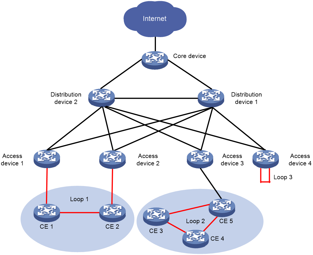
As shown in Figure 8, within the campus access network, the multi-tenant unit switch (MTU-s) and the access device are deployed using a Spine-Leaf structured VXLAN network OR VLAN network. A core device is also deployed as the campus's gateway (GW) for communication with the external network.
Figure 8 Park Networking Diagram
Loop point
Loop point one
Loop point description
The user terminals CE 1 and CE 2, connected to different access devices, can not only communicate through the VXLAN or VLAN network via the access devices, but also through the directly connected Layer 2 network. A loop is formed between the VXLAN or VLAN network and the Layer 2 network, potentially causing a broadcast storm.
Loop Protection Technical (Tech)
After enabling the loop detection function on access device one and access device two:
· In the VXLAN network, either access device one or two will automatically prevent loop AC from MAC address learning and block it to eliminate the loop.
· In the VLAN network, either access device one or access device two can shut down, block the port detecting the loop, or prohibit the port where the loop appears to learn the MAC address, in order to eliminate the loop.
Loop point two
Loop point description
Within the site connected by the access device 3, user terminals CE 3, CE 4, and CE 5 are interconnected in pairs within the second stratum network, forming a loop, thus causing a broadcast storm. Duloop their intercommunication, CE 3, CE 4, and CE 5 may face risks such as out of service.
Loop Prevention Technology
The loop within the three sites of the access device can be eliminated by using the following loop prevention technology.
· On CE 3, CE 4, and CE 5, the Spanning Tree Protocol (STP) is activated. This protocol can identify loops and automatically calculate blocked ports. By blocking ports, the STP eliminates loops.
· Turn on the loop detection function on any of the CE 3, CE 4, or CE 5 devices. The loop detection function will automatically identify the ports where a loop occurs and block or close them to eliminate the loop.
Loop point three
Loop point description
On access device four, a message sent from one interface to a site might be directly received from another interface, thereby forming a loop. This situation is simplified in Figure 8, depicting it as Leaf 4 having a direct connection between the two interfaces within the site.
Loop Protection Technology
On Leaf 4, the loop detection function can be activated. Once this function is turned on, it can automatically detect the ports where loops occur and block or close them to eliminate loops.