- Released At: 18-04-2024
- Page Views:
- Downloads:
- Table of Contents
- Related Documents
-
Intelligent Lossless Network Technology White Paper
Copyright © 2024 New H3C Technologies Co., Ltd. All rights reserved.
No part of this manual may be reproduced or transmitted in any form or by any means without prior written consent of New H3C Technologies Co., Ltd.
Except for the trademarks of New H3C Technologies Co., Ltd., any trademarks that may be mentioned in this document are the property of their respective owners.
This document provides generic technical information, some of which might not be applicable to your products.
Contents
Application requirements for RDMA
Requirement for the development of data center hardware
Triggering the PFC deadlock detection
Operating mechanism of PFC deadlock prevention
Separate scheduling of large and small flows
Technical features provided by H3C iNOF
Overview
Introduction
Intelligent Lossless Network is a network environment that provides "zero packet loss, low latency, and high throughput" for various application scenarios such as artificial intelligence (AI), distributed storage, and high performance computing (HPC). It is achieved through hardware schema, intelligent lossless algorithm, and a series of technical (Tech) network methods. This environment accelerates the efficiency of computing and storage, and facilitates the consolidation of a unified network for data centers.
Background
Application requirements for RDMA
As the global enterprise digitization accelerates, the Internet applications are increasingly integrated into production and daily life, resulting in larger storage networks that need to process more data. Data centers for headquarters and branch offices are deployed in different physical locations, making remote direct memory access (RDMA) the mainstream technology for storage networks. RDMA utilizes relevant hardware and network technology, enabling host network cards to directly read memory and achieve high bandwidth, low latency, and low resource consumption. However, RDMA was initially carried over the lossless Infinite Band (IB) network, with a dedicated closed IB network architecture that was not compatible with existing networks and had higher usage costs. As a result, RDMA over Converged Ethernet (RoCE) was developed.
RoCE uses Ethernet to carry the RDMA network protocol, and there are two versions: RoCEv1 (a link layer protocol, which cannot be used in different multicast domain (MDs)); RoCEv2 (a network layer protocol, which can implement the routing function).
Current high-performance computing (HPC), distributed storage, and artificial intelligence (AI) applications use the RoCEv2 protocol to reduce CPU processing and latency, thus enhancing performance. However, RoCEv2 is based on a connectionless UDP protocol and lacks a comprehensive packet loss protection mechanism, making it highly sensitive to network anomalies. Moreover, distributed high-performance applications utilize a many-to-one communication Incast traffic model. This can cause temporary burst congestion or even packet loss in Ethernet devices' internal queue buffers, resulting in increased latency and decreased throughput, which damages the performance of distributed applications. Therefore, to unleash the true potential of RDMA and break through the network performance bottlenecks in large-scale data center distributed systems, it is essential to establish a lossless network environment with "zero packet loss, low latency, and high throughput" for RDMA.
The Intelligent Lossless Network is a compilation of various technical methods. On one hand, it utilizes traffic control and congestion control techniques to increase the overall throughput of the network and reduce network latency. On the other hand, it implements network and application system consolidation optimization through techniques such as Intelligent Lossless Storage Network.
Requirement for the development of data center hardware
Computing, storage, and network are the three key elements of a data center, and they need to develop in coordination.
The industry has made significant advancements in computing chip power and storage read speeds. From 2016 to 2021, the computing power of GPU/AI chips increased by 90 times. SDD storage media that use the NVMe (Non-Volatile Memory Express) interface protocol offer a 10,000-fold increase in access performance compared to HDD mechanical hard disks. The latency in reading and writing to storage media primarily depends on network latency. As storage media and processors evolve, network communication latency has become the bottleneck hindering further improvements in computing and storage efficiency. Therefore, providing a "lossless network environment with no packet loss, low latency, and high throughput" is a key requirement for the future development of data centers.
Technical architecture
The Intelligent Lossless Network enhances overall network throughput and reduces network latency through traffic control and congestion control technologies. On the other hand, it achieves network and application system consolidation optimization through technologies such as Intelligent Lossless Storage Network. According to the correlation between Intelligent Lossless Network technology and the TCP/IP protocol stack, the technical architecture of the Intelligent Lossless Network is shown as Figure 1.
Figure 1 Intelligent lossless network
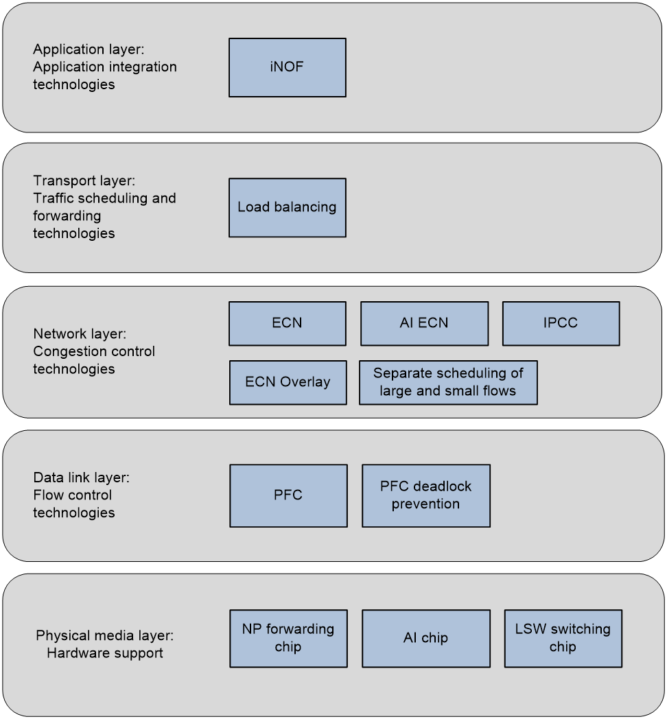
· At the physical hardware layer, a smart lossless network requires the support of AI chips that support intelligent lossless algorithms and chips for forwarding/switching.
· Deploy Priority-based Flow Control (PFC) technology at the data link layer to manage traffic and prevent PFC deadlock issues. The PFC technology, defined by IEEE 802.1Qbb, addresses frame loss due to congestion.
· At the network layer, intelligent lossless networks can apply the following congestion control techniques:
¡ Explicit Congestion Notification (ECN): ECN is an end-to-end congestion notification mechanism that allows the network to avoid discarding packets during congestion, as defined in RFC 3168.
¡ ECN Overlay: ECN is applied to VXLAN networks to enable an end-to-end congestion notification mechanism within the VXLAN network.
¡ Separate scheduling of large and small flows: Device ports use the QoS congestion management technology for queue scheduling when forwarding messages, offering various service standards. In the network, the administrator categorizes traffic into large and small flows and schedules them separately to ensure throughput for large flows and meet latency requirements for small flows.
¡ AI ECN: AI ECN incorporates an intelligent algorithm to predict current traffic models and dynamically adjust the ECN low threshold.
¡ Intelligent Proactive Congestion Control (IPCC) is an active congestion control technology centered on network equipment. It precisely controls the rate at which servers transmit RoCEv2 packets based on the congestion state of device ports.
· ECMP is used at the transport layer to achieve load sharing for network traffic.
· At the application layer, the intelligent lossless network offers the Intelligent Lossless NVMe Over Fabric (iNOF) feature, which enhances the ease of use of storage networks by quickly managing iNOF hosts and achieves the consolidation of Ethernet and storage networks.
Traffic control technology
PFC is one of the essential methods for building lossless Ethernet. It can provide hop-by-hop traffic control based on priorities.
Operating mechanism of PFC
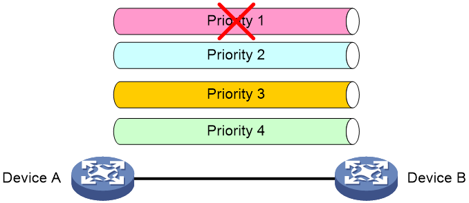
PFC enables network equipment to perform traffic control based on the privilege level of different data flows. When traffic of a specific privilege level experiences congestion, network equipment can transmit a back pressure signal (PFC PAUSE frame) to the peer device, instructing it to stop sending traffic of that privilege level to prevent buffer overflow and data loss. This individual traffic control method allows the network to remain smooth during certain congestion while preventing interference with other traffic.
As shown in the following figure, traffic of multiple priorities exists between Device A and Device B. When congestion occurs in Priority 1 traffic, Device A and Device B will stop transmitting traffic at that priority level. At the same time, traffic with other priorities between Device A and Device B can be processed normally.
Figure 2 Operating mechanism of PFC
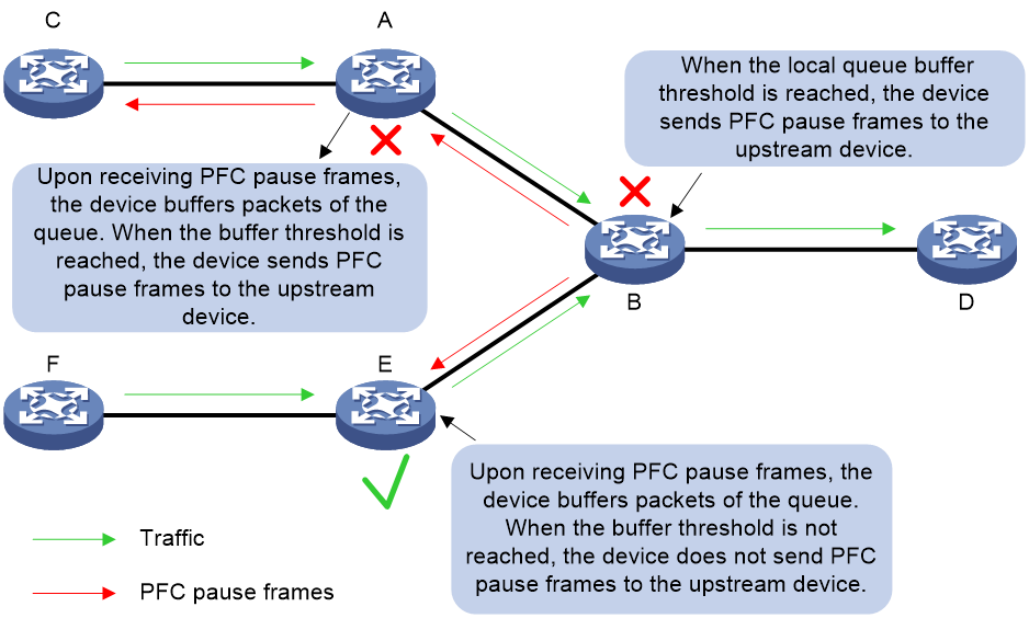
As shown in Figure 3, when a queue on Device B's egress interface experiences congestion, causing the incoming interface buffer of the corresponding traffic on this device to exceed the threshold, Device B transmits a PFC PAUSE frame to all upstream devices (the sources of the datagrams). When Device A receives a PFC PAUSE frame, it will stop transmitting messages at the corresponding priority level as indicated by the PFC PAUSE frame and store the data in the local interface's buffer space. If Device A's local interface cache consumption exceeds the threshold, it will also transmit a PFC PAUSE frame to the upstream devices. The PFC PAUSE frame will be transmitted from one level to the next until it reaches the network terminal, thereby eliminating packet loss caused by congestion at network nodes. After Device E receives a PFC PAUSE frame, it buffers messages for that queue. If the buffer threshold is not reached, it does not send a PFC PAUSE frame to upstream devices.
Figure 3 PFC PAUSE frame processing in a network with multiple device levels
PFC deadlock detection
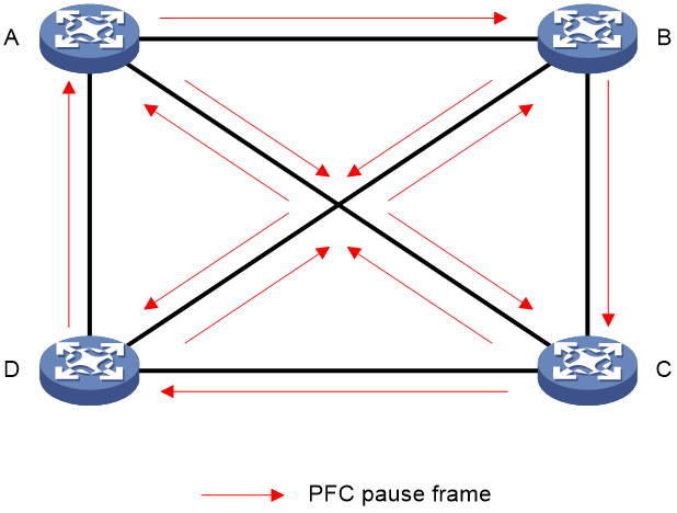
PFC deadlock occurs when multiple devices experience congestion due to loops or similar causes, with each device's port buffer usage exceeding the threshold. They all wait for others to release resources, resulting in a standstill state where the data flow on all switches is permanently blocked.
As shown in the following figure, when multiple devices experience congestion, they transmit PFC PAUSE frames to each other, causing these frames to flood the network. This flood prevents devices within the network from forwarding packets, paralyzing the entire network's operations.
Figure 4 PFC deadlock
Triggering the PFC deadlock detection
As shown in Figure 5, when Device B's Interface port receives a PFC PAUSE frame from Device A, it stops transmitting messages from the corresponding priority queue. Device B starts the PFC deadlock detection timer to monitor the priority queue for received PFC PAUSE frames during the detection period.
Figure 5 Triggering the PFC deadlock detection

PFC deadlock decision
As shown in Figure 6, if the specified priority queue of port Interface on Device B remains in the PFC XOFF state (triggered by the back pressure frame threshold) throughout the PFC deadlock detection period, the queue continuously receives PFC PAUSE frames during this period. Device B will decide that Device A has encountered a deadlock and will enter a deadlock state.
Figure 6 PFC deadlock decision

|
|
NOTE: The PFC back pressure frame threshold is the upper limit of resources used by dot1p priority messages in the buffer space. When the dot1p priority message consumes resources to the upper limit, the device will trigger the transmission of a PFC PAUSE frame. |
PFC deadlock clearance
Upon detecting a deadlock in an interface, the device will initiate an auto-clearance timer. During the automatic clearance period, the device will disable the PFC function and PFC deadlock detection function on the interface to ignore the PFC PAUSE frame received from the interface. Meanwhile, the device will execute actions of forwarding or discarding datagrams (manually configured by the administrator) to mitigate the PFC deadlock issue.
After the auto-clearance timer times out, the device will enable the PFC function and PFC deadlock detection. If the PFC deadlock continues to occur after deadlock auto-clearance, the administrator can set an upper limit for PFC deadlocks. When the number of PFC deadlocks reaches this limit, the device will forcefully disable the PFC function and PFC deadlock detection. After troubleshooting, the administrator needs to manually restore the PFC function and PFC deadlock detection.
PFC deadlock prevention
PFC deadlock prevention refers to identifying the service flows that are prone to cause PFC deadlock, and modifying the corresponding queue priority.
Background
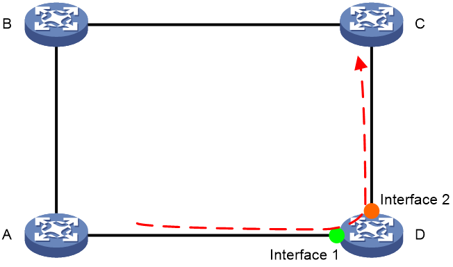
As shown in Figure 7, under normal conditions, the forwarding path for service traffic is A-B-C-D. When the network's loop prevention mechanism fails, it will cause service traffic to be forwarded from D to A. Fault traffic is forwarded between A, B, C, and D, forming a loop. If the resource utilization in the buffer space of network devices A to D reaches the PFC XOFF threshold, the devices transmit a PFC PAUSE frame upstream to control the fault traffic. Continuous transmission of PFC PAUSE frames in a ring network ultimately causes all devices to enter a PFC deadlock state, resulting in a total network flow interruption.
Figure 7 PFC deadlock in a ring network

PFC high-risk service flows
The PFC deadlock prevention feature introduces the concept of port groups, as shown in the following figure, where interface 1 and interface 2 on Device D belong to the same port group. When Device D detects the same flow entering and exiting through an interface belonging to the port group, it determines that the flow is high-risk and prone to forming a PFC PAUSE frame loop, which can lead to a PFC deadlock.
|
|
NOTE: Interfaces with the same PFC deadlock prevention configuration belong to the same port group. For more information about configuring the PFC deadlock prevention feature, see the relevant configuration manual. |
Figure 8 PFC high-risk service flows
Operating mechanism of PFC deadlock prevention
Currently, PFC deadlock prevention only takes effect on service traffic carrying DSCP values.
Currently, PFC deadlock prevention applies only to traffic with DSCP values.
When a device receives a message, it will add the message to a queue with the specified dot1p priority, based on the message's DSCP value and the device's dscp-dot1p mappings. The operating mechanism of the PFC deadlock prevention feature is:
1. Deploy port groups: Administrators should plan ahead and assign interfaces that might generate PFC PAUSE frames to the same port group. For example, assign the upstream ports of a Leaf switch to the same port group.
2. Identify high-risk service flows.
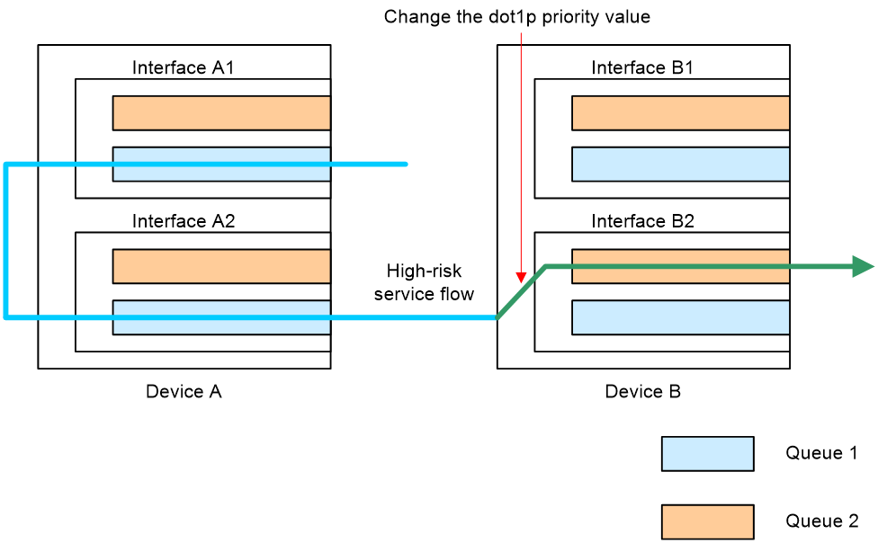
3. Modify mappings: When a device receives a message, it changes the message's DSCP value and the corresponding dot1p priority, allowing the message to be forwarded with the new DSCP value in the new dot1p priority queue.
As shown in the following figure, Device A transmits traffic with the specified DSCP value. When Device B receives the traffic, it forwards the traffic in queue 1 based on the packet's DSCP value and the dscp-dot1p mappings on the device. If Device B detects that the traffic is high-risk and likely to cause a PFC deadlock, it will change the traffic queue's privilege level, directing the traffic to queue 2 for forwarding. This mitigates the potential for PFC PAUSE frames in queue 1, preventing PFC deadlock.
Figure 9 Operating mechanism of PFC deadlock prevention
Congestion control technology
Congestion control refers to a method of controlling the total amount of data entering the network, keeping the network traffic at an acceptable level. The difference between congestion control and traffic control is:
· Traffic control is controlled by the receiving end to regulate the data transfer rate, preventing congestion and package loss caused by the transmitting end sending at too fast a rate.
· Congestion control is a collaborative process involving all devices across the network, where all hosts and forwarding devices participate in controlling the network's data traffic, striving for a network with no packet loss, low latency, and high throughput.
In the current network, traffic control and congestion control need to be combined with applications to truly solve network congestion.
In the current data center network, ECN is the most widely used congestion control method. This section introduces the operating mechanisms of ECN, ECN overlay, separate scheduling of large and small flows, AI ECN, and IPCC.
ECN
Concepts
Explicit Congestion Notification (ECN) is a congestion notification technology. The ECN function uses the DS field in the IP packet header to mark the congestion state on the transmission path. ECN-capable terminals can judge whether congestion has occurred on the transmission path through the ECN mark in the packet, thus adjusting the packet transmit method to avoid exacerbating congestion.
RFC 2481 defines the last two bits in the DS field of the IP packet header as the ECN field:
· Bit 6 is used to identify whether the sending device supports the ECN function, known as the ECN-Capable Transport (ECT) bit.
· Bit 7 is used to identify whether a packet has encountered congestion on its transmission path, known as the Congestion Experienced (CE) bit.
Figure 10 Diagram of the ECN field in the IPv4 packet header
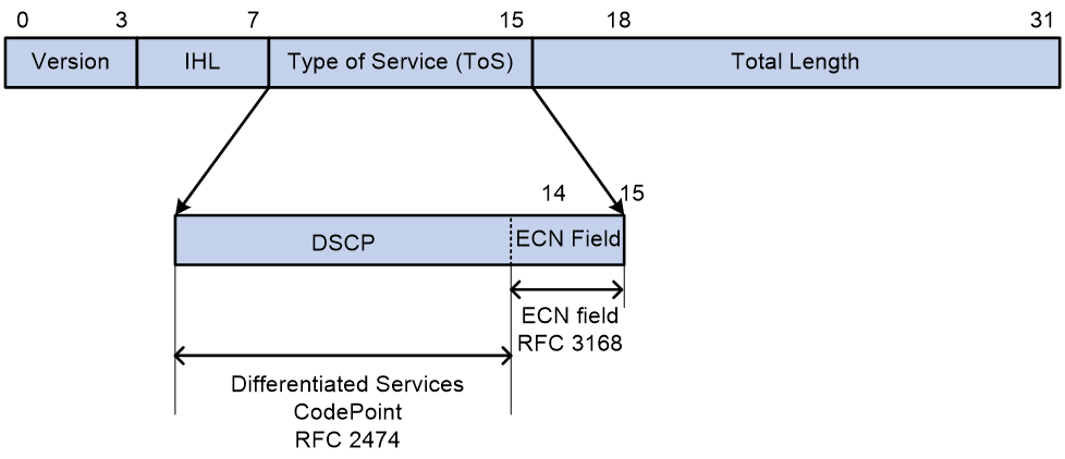
As demonstrated in Figure 10, RFC 3168 defines the values of the ECN field for an IPv4 packet as follows:
· If the value of the ECN field is 00, it indicates that the sending device does not support ECN.
· When the value of the ECN field is 01 or 10, it indicates that the sending device supports ECN, marked as ECT(0) or ECT(1), respectively.
· When the value of ECN field is 11, it indicates that congestion has occurred on the forwarding path of the packet, marked as CE.
Implementation
The ECN function needs to be applied in conjunction with the WRED policy.
As shown in Figure 11, a WRED policy without ECN enabled randomly discards messages in the queue according to a specific drop profile. The WRED policy sets an upper limit length (QL_max) and a lower limit length (QL_min) for each queue and processes the messages in the queue as follows:
· When the queue length is below the lower limit QL_min, do not discard packets.
· When the queue length exceeds the upper limit QL_max, discard all incoming messages.
· When the queue length is between the upper limit QL_max and the lower limit QL_min, start randomly discarding incoming messages. The longer the queue, the higher the probability of discarding. The queue discard probability increases linearly with queue length and does not exceed the maximum discard probability of x%.
Figure 11 WRED discard probability and queue length

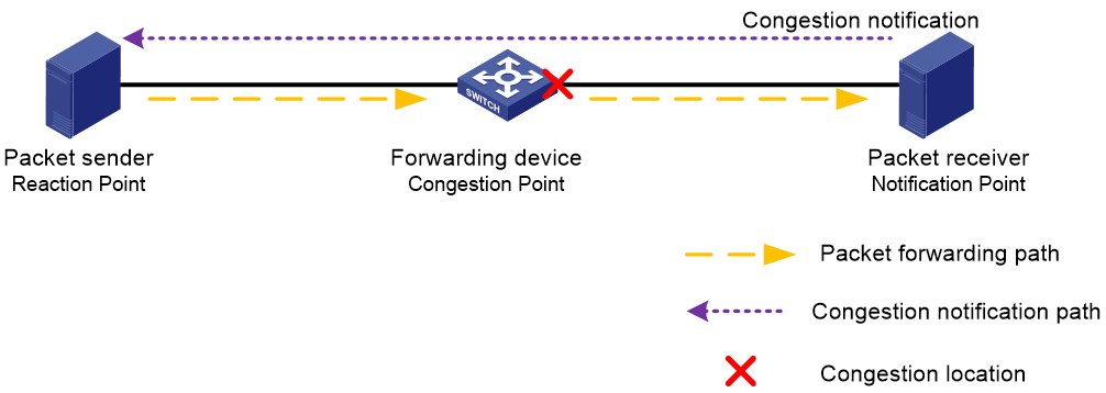
As shown in Figure 12, the network diagram for deploying the ECN feature with WRED policy includes three types of device roles.
· Forwarding device (Congestion Point): A device that packets pass through on their network path. It supports ECN functionality and can identify the values in the ECN field of packets. Packets may experience congestion at the interfaces of forwarding devices, also known as Congestion Points. Therefore, deploy the ECN feature with WRED policy on these devices.
· Packet receiver (Notification Point): The device's network card supports ECN and can identify ECN fields with values of 01, 10, or 11 in messages. The receiver also acts as the initiator of congestion notification. Upon receiving a packet with an ECN field value of 11, it sends a congestion notification to the sender every time period T1, requesting the sender to reduce the packet transmission rate.
· Packet sender (Reaction Point): The network card of the transmitting device supports ECN, and the ECN field of messages sent from this end is either 01 or 10. The sender also acts as the congestion notification response device. Upon receiving a congestion notification, it will reduce its current message transmission rate by a certain deceleration ratio and start a timer. If the timer exceeds time T2 (T2 > T1) and the sender has not received another congestion notification, it assumes there is no congestion in the network and restores the previous message transmission rate. If the sender receives another congestion notification within time T2 (T2 > T1), the sender further reduces the message transmission rate.
Figure 12 WRED policy with ECN deployed
Deployed devices with ECN-enabled WRED policy (Congestion Points) identify and process received datagrams as follows:
· When a packet enters the queuing process in the egress orientation on a forwarding device and the queue length is less than the lower limit QL_min (also known as the ECN lower threshold), the device does not process the packet and directly forwards it from the egress interface.
· When a message from a forwarding device enters the queue in the outbound orientation and the queue length is greater than the lower limit QL_min but less than the upper limit QL_max (also known as the ECN upper threshold):
¡ If a device receives a packet with an ECN field value of 00, it indicates the transmitting end does not support ECN. The forwarding device should process the packet using the WRED policy as if ECN were not enabled, which means randomly discarding the received packet.
¡ If a device receives a packet with an ECN field value of 01 or 10, indicating that the sender supports ECN, it will modify the ECN field of some incoming packets to 11 according to the linear discard probability in the WRED policy and continue to forward the packet. It will not discard any incoming packets.
¡ If a device receives a packet with an ECN field value of 11, it indicates that congestion has occurred on a previous forwarding device. In this case, the forwarding device does not process the packet but directly forwards it from the egress interface.
· When a message from a forwarding device enters the queue for outgoing orientation and the queue length exceeds the upper limit QL_max:
¡ If a device receives a packet with an ECN field value of 00, it indicates that the sending end does not support ECN. The forwarding device should process according to the WRED policy as if ECN were not enabled, which means discarding the received packet.
¡ If a device receives a message with an ECN field value of 01 or 10, this indicates that the message sender supports ECN. Change the ECN field of the incoming message to 11 and then forward the message. Do not discard any received incoming messages.
¡ If a device receives a packet with the ECN field set to 11, it means the packet has already experienced congestion in a previous forwarding device. In this case, the forwarding device does not process the packet but directly forwards it from the egress interface.
Set the ECN threshold appropriately to alleviate congestion while ensuring network latency and throughput.
The modification process of the above ECN field ID occurs when a forwarding device detects congestion in outgoing messages and alters the ECN field ID of incoming messages. During processing, devices experience some delay. To accelerate this process, forwarding devices directly modify the ECN field ID of outbound messages when congestion is detected in the outbound queue. This technique is called Fast ECN.
Compared to a WRED policy without ECN, a WRED policy with ECN offers the following advantages:
· Setting a proper lower threshold allows devices to detect congestion on the path in advance and have the receiving end notify the transmitting end to slow down the transmission rate.
· The forwarding device marks the ECN field as 11 for packets exceeding the lower threshold. This avoids the process of message discard and retransmission in the network, reducing network delay.
· When congestion occurs in the network, the sender gradually lowers the packet transmission rate within a certain time. After congestion disappears, the sender gradually increases the rate to avoid rapid changes of network throughput before and after congestion.
ECN overlay
Concepts
The ECN overlay feature refers to implementing ECN within a VXLAN network. Specifically, when congestion occurs at a device's egress interface, the ECN field of a packet can be marked as CE. The device can then transmit packets carrying the CE mark without losing the ECN field's mark information.
Implementation
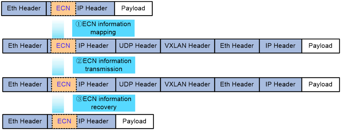
In a VXLAN network, the process for handling the ECN field in messages and the method for conveying ECN information vary slightly depending on the location of congestion. As shown in the following figure, the process for handling the ECN field of a packet and the transmission of ECN information on the egress interface of a VXLAN tunnel ingress node is as follows:
1. ECN information mapping: When congestion is detected at the start of a VXLAN tunnel, the device marks the ECN field of the original IP packet as CE. When transmitting a message, encapsulate the original IP packet with VXLAN. During this process, the device maps the CE field of the ECN domain from the original IP packet to the ECN domain of the outer IP header of the VXLAN packet.
2. ECN information transmission: Messages transmitted in a VXLAN network will carry the CE mark, and intermediate devices in the underlay will not modify it.
3. ECN information recovery: At the termination point of the VXLAN tunnel, when decapsulating VXLAN packets, execute the reverse of the first step, which is copying the information from the ECN field of the outer IP header of the VXLAN packet into the ECN field of the original IP packet.
If congestion occurs on the egress interface of an intermediate device in a VXLAN network, mark only the ECN field of the outer IP header of the VXLAN packet on the Underlay's intermediate device. At the end of the VXLAN tunnel, copy the information from the ECN field into the ECN field of the original IP packet. If congestion occurs on the egress interface of the VXLAN tunnel's egress node, simply execute the above ECN information restoration steps.
Figure 13 Operating mechanism of ECN overlay
Separate scheduling of large and small flows
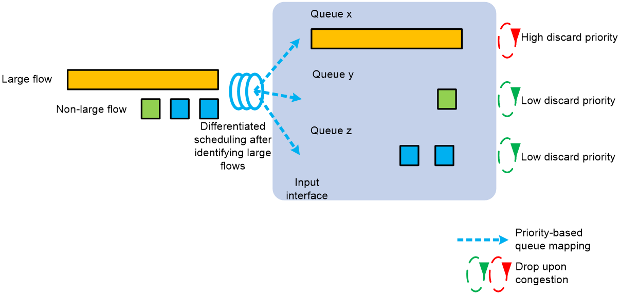
Networks are filled with various types of traffic, which we can simply categorize into large flows and small flows. Large flows account for about 10% of total network traffic but carry 85% of the total data volume. They have large sizes, consume significant bandwidth, and are relatively few in number. However, they have lower latency requirements, such as video frequency downloading traffic. A mice flow is large-sized and occupies low bandwidth, but has high requirements for the delay and needs a fast response. For example, the data query flow is a mice flow. In a lossless network, we aim to schedule small and large flows separately to meet the latency requirements of small flows and the throughput requirements of large flows.
As shown in the following figure, the scheduling mechanism for differentiating between large and small flows is as follows:
1. Use this feature to configure large flow identification parameters (rate and size), enabling the device to identify large traffic flows in the network based on these parameters.
2. Network administrators assign drop precedence, local preference, or dot1q priority to large flows. The device maps identified large flows to specific queues based on local preference or dot1q priority, scheduling them separately from other flows. When congestion occurs, the device can prioritize dropping large flow packets based on the configured drop precedence to ensure a low latency experience for small flows.
Figure 14 Separate scheduling of large and small flows
AI ECN
Background
The signature of the data flow traffic forwarded by each queue dynamically changes over time. Static ECN threshold settings by the network administrator cannot meet the needs of real-time, dynamically changing network traffic characteristics.
· If the ECN threshold is set too high, the forwarding device uses longer queues and more buffers to ensure the rate of traffic transmission, meeting the bandwidth requirements of large flows. However, during congestion in the queue, packets waiting in the buffer can cause significant queue delay, which is unacceptable for small, latency-sensitive flows.
· If the ECN threshold is set too low, the forwarding device uses shorter queues and less buffers to reduce the queuing delay in the queue, meeting the latency requirements of small flows. However, a low ECN threshold can reduce network throughput, limiting transmission of large flows.
On the other hand, if both PFC and ECN features are deployed in the network, we want the ECN threshold settings to ensure that the ECN feature is triggered first, reducing the message transmission rate to alleviate congestion, rather than triggering the PFC feature to directly instruct the sender to stop transmitting messages. Trigger the PFC feature only if congestion worsens and does not alleviate after ECN activation. In this case, notify the transmitter to stop datagram transmission until congestion eases, then inform it to resume sending datagrams. When deploying ECN and PFC together to mitigate congestion, follow the sequence of operations as shown in the diagram below:
Figure 15 ECN and PFC work together to alleviate congestion
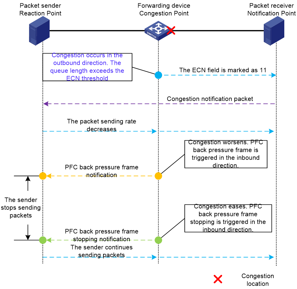
Figure 15 shows that when congestion occurs, the forwarding device sends datagrams with the ECN field marked as 11 to the source to reduce its rate. However, the source continues to transmit datagrams at the original rate during this time, further worsening network congestion. To avoid triggering PFC and affecting network throughput, set the ECN lower threshold reasonably and dynamically.
Due to the previous reasons, an intelligent real-time ECN lower-threshold control function, which is called AI ECN, is introduced.
Implementation
AI ECN dynamically optimizes ECN thresholds using the device's local AI business components, according to a specific traffic model algorithm.
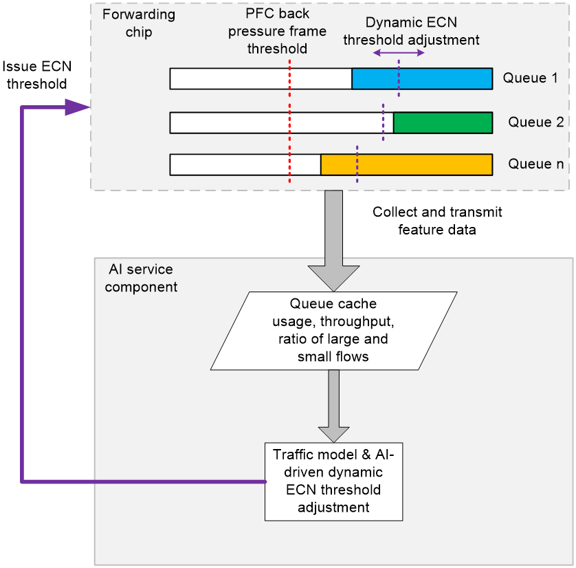
The forwarding chip within the device collects signature data of current traffic, such as queue buffer occupancy, traffic throughput, and the ratio of large and small flows. It then transmits real-time network traffic information to the AI component.
After enabling the AI ECN feature, the AI component intelligently assesses the traffic signature upon receiving the pushed traffic state information to determine if the current network traffic scenario matches a known traffic model.
· If the traffic model matches one of many known traffic models, the AI component will infer the optimal real-time ECN threshold based on the known traffic model.
· If the traffic model does not match any known models, the AI component will continuously adjust the current ECN threshold in real time, based on the live network state, to ensure high bandwidth and low latency. This process will determine the optimal ECN threshold configuration.
Finally, the AI component issues the optimal ECN threshold to the device's forwarding chip to adjust the ECN threshold.
Use AI ECN to adjust ECN thresholds in real time based on traffic signatures and changes.
· When a queue has a high proportion of small flows, the ECN triggering threshold is reduced to ensure low latency for small flows.
· When a queue has a high proportion of large flows, the ECN triggering threshold is increased to ensure high throughput for large flows.
IPCC
Concepts
IPCC is similar to ECN. It also notifies the sender to reduce the message transmission rate through congestion notification messages, thereby avoiding network congestion. IPCC is a congestion control technology initiated actively by network devices. When an interface that forwards RoCEv2 packets is enabled with IPCC, the device proactively transmits congestion notification messages based on the interface's congestion status to notify the sender to reduce the transmission rate. The device intelligently calculates the number of congestion notifications needed, based on the severity of congestion in the interface queue, to precisely adjust the control of the sender's transmission rate reduction, preventing excessive speed reduction.
The comparison between IPCC and the traditional ECN technology is shown in Table 1.
Table 1 Comparison between IPCC and traditional ECN
|
Technical comparison item |
IPCC |
Traditional ECN |
|
Devices that transmit congestion notification messages |
Network devices that forward traffic |
Message receiver |
|
Response to packet congestion |
Direct and active response. A device where congestion occurs in the network transmits a congestion notification to the message source, quickly triggering the source to reduce speed. |
Passive response. Marked packets must propagate along the entire forward path to the receiver, which then sends a congestion notification message to inform the transmitter to slow down. |
|
The effect of reducing the transmission speed |
Network devices with congestion points intelligently calculate the number of congestion notification messages to transmit based on the queue length and buffer usage on the congested interface, precisely controlling the speed reduction at the sender end. |
If the receiver continuously receives packets with an ECN field value of 11, it will send congestion notification messages to the sender at regular intervals to reduce the transmission speed. The reduction effect lags behind the actual congestion point change. |
|
Application scenario |
Applies only to RoCEv2 packets. |
Applies to TCP messages, UDP messages, and other messages. |
|
Hardware support requirements |
Requires support from hardware chips and drivers. |
Requires support from hardware chips and drivers. |
Table 1 shows that IPCC is developed on the basis of the ECN feature, enabling forwarding devices to transmit congestion notification messages. This allows more accurate and swift congestion control in the network.
Implementation
The IPCC feature only applies to RoCEv2 packets. The following briefly introduces the structure of RoCEv2 packets and their key information.
RoCEv2 and InfiniBand are the leading RDMA protocols. Unlike InfiniBand, RoCEv2 is an RDMA protocol based on Ethernet. As shown in Figure 17, RoCEv2 is encapsulated within the UDP protocol, where the destination port number for RoCEv2 packets is fixed at 4791. The main changes between RoCEv2 and InfiniBand occur at the data link layer and network layer. RoCEv2 packets at the transport layer inherit the structure and information from InfiniBand's Base Transport Header and Extended Transport Header at the transport layer.
Figure 17 Comparison between RoCEv2 versus InfiniBand message formats
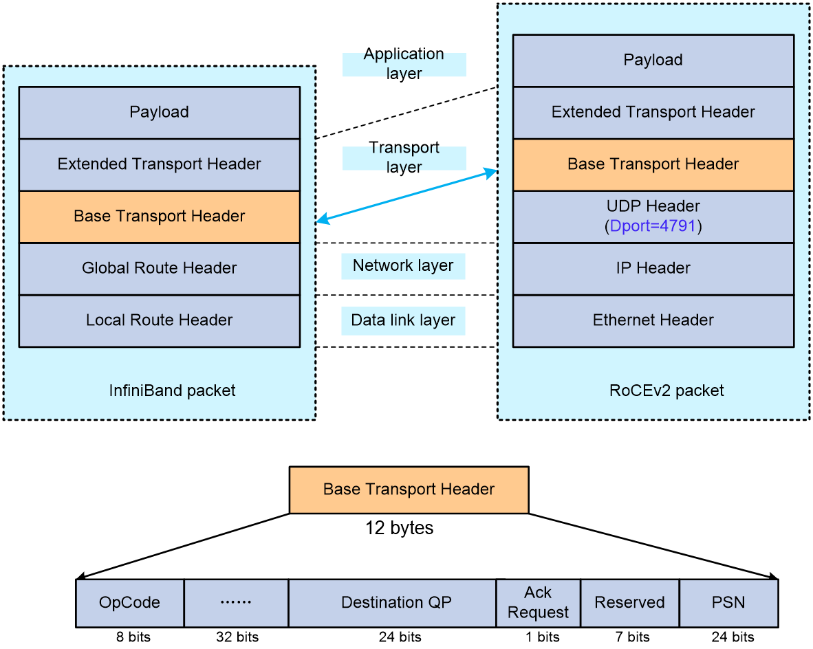
According to the definitions in the InfiniBand Architecture specification, the Base Transport Header (BTH) contains key information for RoCEv2 messages, with the meanings of some fields as follows:
· OpCode indicates the operation type for RoCEv2 and identifies the type of Extended Transport Header (ETH) that follows the BTH. The specific types include, but are not limited to:
¡ Send: The sender requests data transfer to a remote destination without specifying the address where the receiver should store the data.
¡ RDMA Write: The sender requests data writing to a remote end. The sender specifies the receiver's storage address, key, and data length in the message.
¡ RDMA Read: The sender requests data reads from a remote end by specifying the address, key, and data length in the message.
¡ ACK: Indicates an ACK message, which is a response sent by the remote end after receiving a set of RoCEv2 messages.
RoCEv2 messages with operation types Send, Write, and Read are also known as RoCEv2 datagrams.
· Destination QP (Destination Queue Pair): The queue number at the destination end, used to identify a RoCEv2 flow. Typically, when executing a Send, RDMA Write, or RDMA Read operation in a RoCEv2 datagram, both the sender and the destination create a queue, forming a Queue Pair (QP). Use the transmit queue to store messages and requests from the sender, and the receive queue to store messages or requests sent from remote ends. The Destination QP is the key information for establishing RoCEv2 flow tables.
· ACK Request: A flag indicating whether a response with an ACK is requested from the remote end.
· PSN (Packet Serial Number) indicates the sequence number of RoCEv2 messages. By checking if PSNs are consecutive, one can determine if any packets are missing. If packet loss occurs, an NAK message will be returned.
Figure 18 Conceptual Diagram of IPCC's Working Principle

The operating mechanism of the IPCC is shown in the above figure.
· Create a RoCEv2 flow table: On a forwarding device, enable the IPCC feature on the interface to replicate RoCEv2 datagrams passing through the device and send them to the CPU for processing. Create a RoCEv2 flow table based on the source IP address, destination IP address, and destination QP information of the RoCEv2 packet. The RoCEv2 flow table includes information about the ingress and egress interfaces, as well as the related egress interface queue.
When RoCEv2 traffic is present continuously, the device maintains persistence of the RoCEv2 flow table. If congestion occurs on the egress interface, you can identify the incoming and egress interfaces for the flow by referring to the RoCEv2 flow table.
· Intelligently calculate the number of congestion notification messages: Monitor queues with IPCC enabled on the forwarding interfaces, and intelligently calculate the number of congestion notification messages to transmit based on queue length and the ratio change of queue space utilization.
¡ When the queue length increases and the queue buffer utilization is low, transmit a small number of congestion notification messages to the sender to alleviate congestion without causing the sender to reduce speed excessively.
¡ When the queue length increases and the queue buffer utilization is high, transmit more congestion notification messages to the sender to quickly alleviate queue congestion and reduce forwarding latency.
¡ When the queue length decreases and the queue buffer utilization is low, do not transmit congestion notification messages to the sender to prevent throughput reduction due to decreased speed.
¡ When the queue length decreases and the queue buffer utilization is high, transmit a small number of congestion notification messages to the sender to alleviate congestion while ensuring throughput and latency performance.
The forwarding device constructs congestion notification messages based on the address information in the RoCEv2 flow table and actively transmits them to the Tx end. The number of congestion notification messages transmitted equals the message count calculated in the previous step. Upon receiving congestion notification messages, the sender alleviates network congestion by reducing the transmission rate of RoCEv2 packets.
The IPCC feature overcomes the limitations of traditional ECN by using a more refined algorithm to determine when and how to transmit congestion notification messages. This improvement method relies on real-time analysis of network status to calculate the appropriate congestion notification message transmission frequency. This mechanism ensures the swift and precise transmission of congestion notifications to alleviate network congestion promptly without causing unnecessary performance degradation. The IPCC feature enhances network efficiency and stability by dynamically adjusting notification message transmission to optimize traffic management.
iNOF
Introduction
As global enterprises accelerate their digitization transformation, Internet applications penetrate deeper into production and daily life. The scale of storage networks is expanding, and the amount of data needing processing is increasing. Data centers for headquarters and branch offices are deployed in different physical locations, making RDMA (Remote Direct Memory Access) a mainstream technology in storage networks. RDMA leverages related hardware and network technologies to enable direct memory reading between host network cards, achieving high bandwidth, low latency, and low resource consumption. However, RDMA was initially designed for lossless IB (InfiniBand) networks with a proprietary and closed schema, incompatible with existing networks and costly. Thus, RoCE (RDMA over Converged Ethernet) emerged.
RoCE employs an Ethernet-based network protocol to carry RDMA, with two versions: RoCEv1 is a link layer protocol that cannot be used across different multicast domains; RoCEv2 is a network layer protocol that enables routing capabilities.
Current applications such as high performance computing, distributed storage, and artificial intelligence all adopt the RoCEv2 protocol to reduce CPU processing and latency, thereby enhancing application performance. The RoCEv2 protocol lacks a robust packet loss protection mechanism, and storage services are highly sensitive to network packet loss anomalies. To unleash the true performance of RDMA within a large Ethernet environment and break through the network performance bottleneck of large-scale distributed systems in data centers, we have constructed a lossless network environment for RDMA that ensures "zero packet loss, low latency, and high throughput" using intelligent lossless network technology.
An intelligent lossless network is a collection of technologies that enhance overall network throughput and reduce latency through traffic control and congestion control techniques. It also achieves network and application system consolidation and optimization through technologies like intelligent lossless storage networks.
iNOF (Intelligent Lossless NVMe Over Fabric) is a technology that consolidates and optimizes Ethernet and storage networks. It enables the auto-discovery of massive storage devices, quick detection of network outages, and immediately notifies all devices within the intelligent lossless network of the storage devices' connection and disconnection. This provides foundational support for achieving a "zero packet loss, low latency, high throughput" lossless network.
iNOF networking
iNOF supports two typical networking configurations: direct iNOF networking and cross-switch iNOF networking. Each configuration uses different mechanism, suiting different scenarios.
iNOF network elements
An iNOF network includes the following elements:
· Host—iNOF-capable network servers and disk devices.
· Switch—iNOF-capable switches that provide network access to iNOF hosts.
· Zone—iNOF introduces the concept of zone to manage hosts. An iNOF zone has multiple hosts. When you add a new host into or remove a host from the zone, iNOF informs this event to other hosts in that zone. iNOF zones are divided into the following types:
¡ User-defined zone—A user-defined zone is created by users. Users must add hosts into the zone manually according to network requirements.
¡ Default zone—By default, an iNOF switch has a default iNOF zone that cannot be deleted. Users can select whether to enable automatic adding of free hosts to the default zone. A free host refers to a host that is not a member of any user-defined zones.
Directly connected network
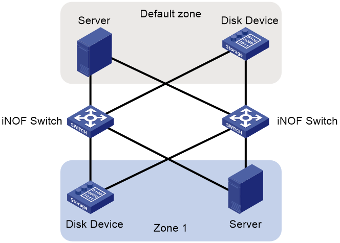
As shown in Figure 19, the hosts in an iNOF zone connect to the same iNOF switch. Each host exchanges Layer 2 packets with the switch to ensure they are aware of the state changes of connected hosts. Switches do not exchange iNOF information with each other. This iNOF network type is applicable to small networks.
Figure 19 Directly connected network
Cross-switch network
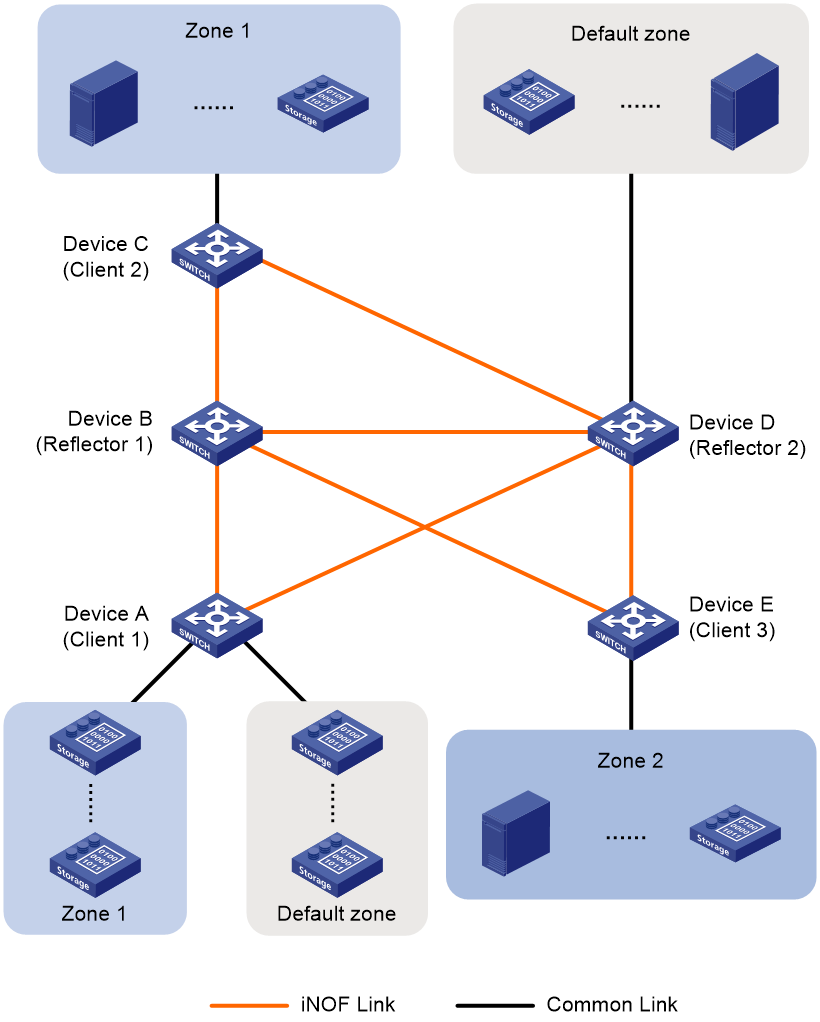
As shown in Figure 20, the hosts in the same iNOF zone can connect to different iNOF switches. These switches exchange dynamic host information. This iNOF network type is applicable to large-scale data centers with multiple hosts from different organizations or departments. The hosts in the same organization or department connect to different iNOF switches.
A cross-switch iNOF network is established as follows:
· Each host directly connects to an iNOF switch. They communicate with each other in the same way as they do on the directly connected iNOF network.
· The iNOF switches establish IBGP sessions to each other and use route reflection to simplify the network. Other switches can promptly receive the state changes of iNOF hosts connected to a switch. In BGP iNOF address family, iNOF switches exchange iNOF route information that includes dynamic iNOF host information and iNOF configuration information.
Figure 20 Cross-switch network
|
|
NOTE: · To simplify a cross-switch iNOF network, configure a minimum of one switch as the iNOF reflector and the rest of switches on that network as iNOF clients. All clients establish iNOF connection with the iNOF reflector and each host directly connects to an iNOF reflector or client. To avoid unexpected or unsolvable issues during frequent route changes, do not establish any iNOF connections between clients. · To improve network availability, you can specify multiple route reflectors for an iNOF zone. The failure of a reflector does not affect service continuity, because other reflectors still run normally. These route reflectors and their clients automatically form a cluster. The route reflectors in the cluster must have the same cluster ID to avoid routing loops. |
Benefits
iNOF has the following basic benefits:
· Plug and play
The iNOF switch can discover a new host as soon as the host accesses the iNOF network. Then, it synchronizes this change to other switches on the network and other hosts in the iNOF zone to which the new host belongs. Hosts in the same zone will automatically establish connections with the new host to ensure fast storage service expansion.
· Fast network failure detection
The iNOF switch can detect network failures promptly and forward this event to other switches on the network and the hosts connected to that switch. Hosts disconnect from the storage devices affected by network failures and use redundant paths to ensure service continuity.
Technical features provided by H3C iNOF
H3C has expanded the mature BGP technology to enable iNOF inter-switch networking, which has the following features:
· iNOF uses BGP for connection establishment of iNOF links, with the transport layer utilizing TCP protocol to provide a stable connection for transmitting iNOF information.
· iNOF leverages the extensive routing policy provided by BGP to flexibly filter and select iNOF routes.
· iNOF uses the route reflection feature to effectively reduce the number of iNOF connections in large-scale iNOF networks. This simplifies network topology and lowers maintenance costs. After the administrator configures the iNOF domain and member hosts on the reflector, iNOF can automatically synchronize these settings to the clients, simplifying the deployment and configuration of iNOF.
· iNOF utilizes BGP's Graceful Restart and Nonstop Routing features to ensure uninterrupted transmission of iNOF information during an active/standby switchover or when the BGP protocol restarts on iNOF switches.
· iNOF uses BGP connections and supports BGP-BFD collaboration, enabling iNOF to quickly detect link faults.
· iNOF uses various encryption methods for BGP sessions, such as MD5 authentication, Generalized TTL Security Mechanism (GTSM), and keychain authentication, to enhance the security of connections between iNOF switches.
Related documentation
· RFC 3168 The Addition of Explicit Congestion Notification (ECN) to IP
· Annex 17 RoCEv2
· iNOF Technology White Paper
