- Released At: 05-06-2025
- Page Views:
- Downloads:
- Table of Contents
- Related Documents
-
H3C G6 Servers HDM2 MCTP Technology White Paper
Copyright © 2025 New H3C Technologies Co., Ltd. All rights reserved.
No part of this manual may be reproduced or transmitted in any form or by any means without prior written consent of New H3C Technologies Co., Ltd.
Except for the trademarks of New H3C Technologies Co., Ltd., any trademarks that may be mentioned in this document are the property of their respective owners.
The information in this document is subject to change without notice.
Contents
MCTP control messages and control protocol
Out-of-band management of PMC RAID adapters
Out-of-band acquisition of FC HBA information
MCTP introduction
Overview
Management Component Transport Protocol (MCTP) is a physical media-independent protocol for information exchange among components in a computer system. This protocol is independent of the underlying physical bus and is a "data link layer" protocol independent of the bus.
MCTP is defined by the Distributed Management Task Force Platform Management Component Intercommunications (DMTF PMCI). This protocol provides interfaces to access the monitoring and management functions of the platform management subsystem, so that manageable functions of the platform can be accessed, transmitted, and configured through the DMTF Common Information Model (CIM).
MCTP base protocol
The basic unit of data transfer in MCTP is the MCTP packet. One or more MCTP packets are used to transfer an MCTP message. The base protocol defines the common fields for MCTP packets and how they are used. The defined fields include source and destination address fields, fields that identify which packets belong to a particular MCTP message, and fields that define what type of communication traffic is being carried in the MCTP message. The base protocol also defines the processes used for assembling MCTP messages, routing MCTP packets, and handling error conditions such as dropped or missing packets.
MCTP Endpoints and EIDs
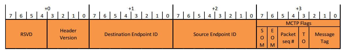
An endpoint on the MCTP link receives MCTP packets and handles MCTP control commands. MCTP uses a logical address called the endpoint ID (EID) for addressing and routing MCTP packets to and from endpoints.
An MCTP packet header contains the destination EID and source EID, as shown in Figure 1:
MCTP buses
An MCTP bus is defined as an internal connection between platform components. An MCTP bus may be made up of multiple segments. A bus segment is a portion of a bus that is separated from other segments that form the bus, but still shares a common physical address space with other segments.
MCTP bus owners and bridges
Each MCTP bus has a bus owner. Bus owners are responsible for assigning EIDs to any MCTP devices on that bus. A bus owner may also have additional specific responsibilities, such as device discovery and assignment of physical addresses.
MCTP bridges are devices that connect to two or more MCTP buses and are responsible for routing MCTP packets between those buses. A bridge is typically also the bus owner for at least one of the buses to which it connects.
MCTP allows multiple bridges, buses, and bus owners to be interconnected to form an MCTP network. Because bus owners are responsible for assigning EIDs to any devices that are on the bus that it owns, MCTP provides a mechanism that enables bus owners to be allocated a pool of endpoint IDs that can subsequently be assigned or allocated to other devices. The ultimate source of EIDs for the entire MCTP network comes from what is referred to as the "topmost bus owner."
MCTP bus owners and bridges are also responsible for providing a service that enables resolving EIDs into physical addresses so that the originator of an MCTP packet knows what destination physical address needs to be used to route a message to a given EID.
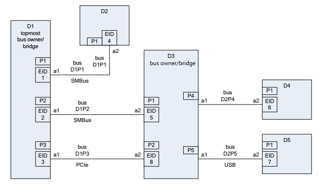
Figure 2 is an example of the MCTP network, which includes the "topmost bus owner" (D1), bus owner (D3), bridges (D1 and D3), and MCTP endpoints (D2, D4, and D5).
MCTP packet routing
MCTP packets are routed based on their EIDs. MCTP bridges maintain a set of information referred to as the "routing table" that tracks the relationship between the physical addresses and bus with which an EID is associated. When the MCTP bridge receives an incoming packet, the routing table is used to route the packet to the appropriate bus. If the source and target buses use different physical media, the bridge is also responsible for translating the physical layer format of the packet as required by the target medium.
The routing table is also used for handling requests to resolve an EID into a physical address and to support a capability to query individual bridges and bus owners for their routing information. This latter capability provides a way to obtain a snapshot of the MCTP network’s routing configuration.
The MCTP bridge simply forwards packets based on endpoint addressing information on a per packet basis. The MCTP bridge does not interpret message content, or handle message type-specific protocol behavior for routed packets. In addition, the MCTP bridge does not perform intermediate assembly or disassembly of routed packets. Message assembly and disassembly are handled solely by the destination and source endpoints, respectively.
MCTP packet routing between buses does not include a broadcast capability, but some individual buses may support broadcast as required by the particular medium to support device discovery. This eliminates the complexity of having bridges replicate and transmit packets across multiple buses.
MCTP message types
MCTP can carry packets for multiple message types across a common communications medium. The MCTP base protocol specification defines a message type for MCTP control messages and message types that support vendor-defined MCTP messages. Other message types, such as the message type that support
Platform Level Data Model (PLDM), are defined in separate specifications.
Different message types are identified by a message type field in the MCTP
message header. The value of this field is specified in the specification that
defines the message type. For definitions of values of the MCTP message type
field, see the Management Component Transport Protocol
(MCTP) IDs and Codes (DSP0239). Figure 3 shows
the format of a PLDM over MCTP packet.
Figure 3 PLDM over MCTP packet format

MCTP control messages and control protocol
The MCTP base specification includes the definition of the message type for "MCTP control messages." These messages are used by bus owners to initialize and maintain the routing table used in an MCTP network. MCTP control messages also help determine whether an endpoint delivers MCTP messages normally.
The MCTP control protocol defines the format of MCTP control messages and how they are delivered and acknowledged. Almost all control messages are delivered using a request/response mechanism, where a request message is delivered to a target or "responder" endpoint using an MCTP message transfer, and then later the responder delivers a response message back to the requester. Response messages provide a positive acknowledgment of the receipt and handling of the request and return data according to the request.
The control protocol also supports broadcasting of unacknowledged messages on the bus. This mechanism can be used for device discovery. The control protocol includes a retry mechanism to help ensure reliable delivery of requests, and to cover cases where a responder may be briefly off-line. The control protocol also defines fields that are used to identify requests and responses, and to identify whether a message is a packet or a retransmitted packet.
Characteristics
MCTP is independent of the underlying physical bus. It realizes message transmission on the bus similar to the "data link" layer, and supports data communication on the specified physical media, such as MCTP over PCIe and MCTP over SMBus/I2C. MCTP defines an extensible transport binding protocol to support other buses (such as USB and Reduced Media Independent Interface (RMII)) without affecting the MCTP base protocol specification.
In addition to the message types defined in the basic protocol specification, MCTP also supports other types of messages over MCTP, for example, PLDM over MCTP and Network Controller Sideband Interface (NCSI) over MCTP.
In summary, MCTP has the following characteristics:
· It is applicable to different computer systems, such as servers and mobile devices.
· Its simple protocol features are suitable for low-consumption microprocessors.
· It improves the management speed and reliability of system components, and enhances the performance and design flexibility of the whole system.
HDM MCTP implementation
MCTP has been implemented on the Intel platform, and its implementation principle is as follows:
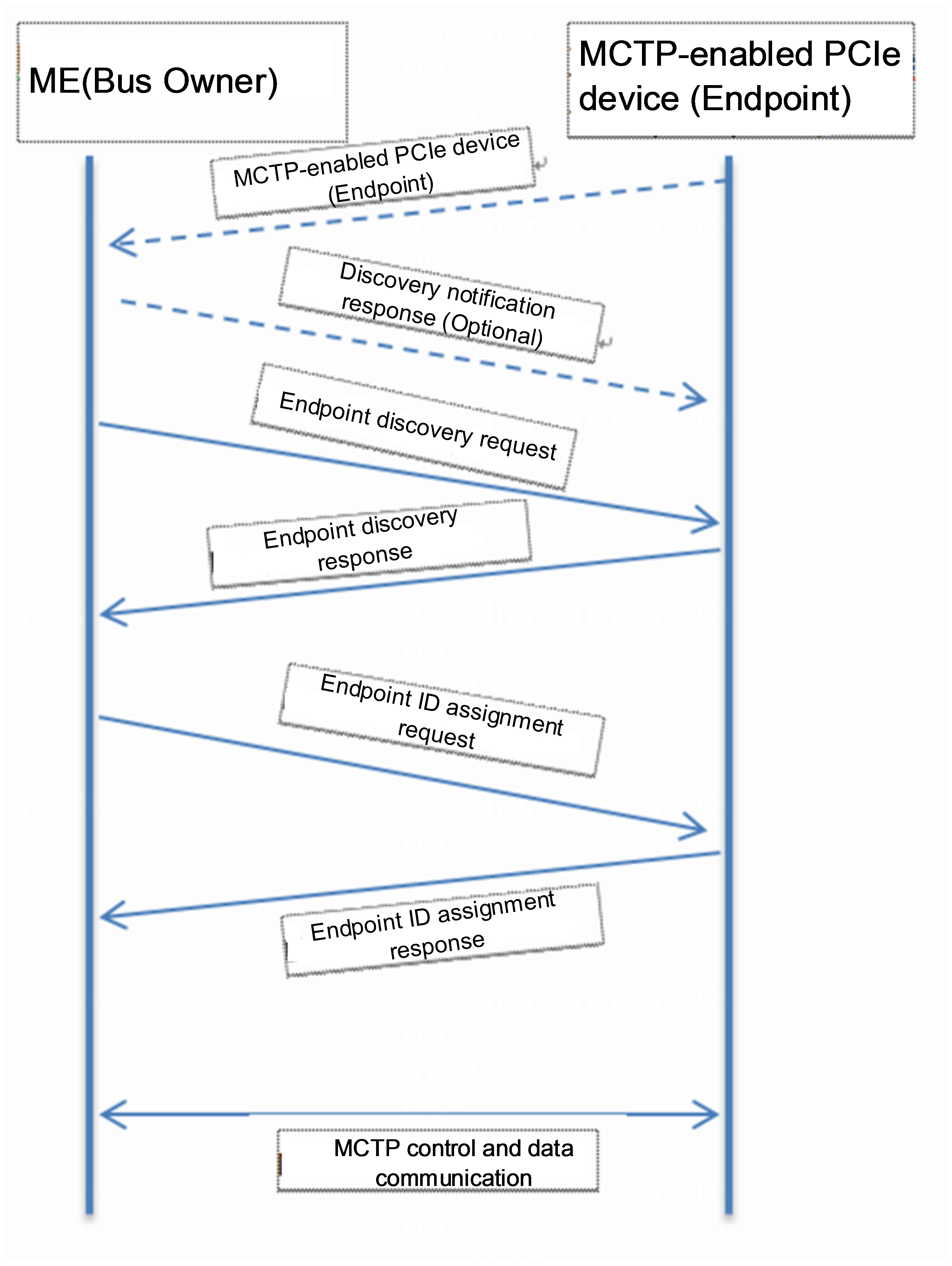
Intel Management Engine (ME) acts as the bus owner, and establishes MCTP communication with PCIe devices that support MCTP. To support the out-of-band management of MCTP, HDM needs to send a request to the ME to obtain the bus owner proxy permission. Then, HDM can establish MCTP socket communication with the host-related MCTP components, and create tasks such as message processing.
Figure 4 shows the MCTP communication process between the ME and PCIe device.
Figure 4 MCTP communication process
As from Genoa, AMD platforms support connecting external MCTP hosts (using BMC as the external host) through PCIe for managing MCTP over PCIe devices. In systems with a single PCIe segment configuration, a PCIe MCTP host directly sends and receives MCTP messages to other MCTP endpoints through a processor root port without an internal MCTP bridge. Within a single PCIe segment, the processor can route MCTP messages between up to 8 root complexes. Once the external host is enabled, BMC can act as the MCTP bus owner and send broadcast commands to each MCTP device.
HDM realizes the out-of-band management of various components over MCTP, including obtaining the network adapter related information through NCSI over MCTP, and managing the PMC RAID adapters, FC HBAs and other components through MCTP over PCIe.
Out-of-band management of PMC RAID adapters
HDM supports out-of-band management of PMC RAID adapters through MCTP over PCIe. Compared with the traditional management through PMC BMC Service Interface (PBSI), MCTP provides more comprehensive management functions. MCTP over PCIe helps HDM to quickly manage the PCIe devices in the system and improve reliability of system management. This method also features fast speed of signal bus and strong anti-interference ability.
HDM now is compatible with the following MCTP-enabled PMC adapters: UN-RAID-P460 and UN-RAID-H460.
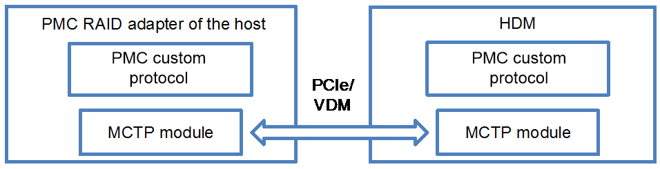
HDM uses the PMC-customized message type "Over MCTP Over PCIe" to access and manage the corresponding RAID adapters. The architecture is shown in Figure 5.
Figure 5 Accessing the RAID adapter
Out-of-band acquisition of FC HBA information
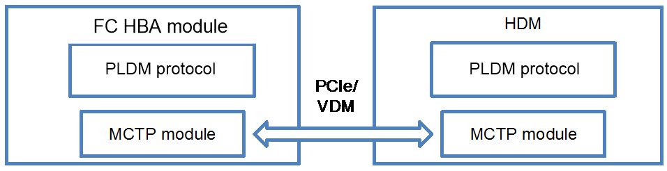
Before MCTP is supported, the FC HBA can only obtain the PCIe information of the network adapter through the BIOS. After MCTP is supported, HDM can directly obtain the network adapter information of the FC HBA, including the WWNN, WWPN, temperature, health status, connection status, and speed. Wherein, WWNN and WWPN are fixed information, and the temperature, health status, connection status, and speed need to be obtained in real time.
HDM now is compatible with the following FC HBAs:
LPe31000, LPe31002, LPe32000, and LPe32002 supplied by Emulex
QLE2690, QLE2692, QLE2740, and QLE2742 supplied by Qlogic
HDM uses "PLDM Over MCTP Over PCIe" out-of-band to obtain information about FC HBAs. The architecture is shown in Figure 6.
Figure 6 Obtaining the FC HBA information
Acronyms
|
Term |
Description |
|
MCTP |
Management Component Transport Protocol |
|
SMBUS |
Name of a multi-master, two-wire, serial bus specified by the Smart Battery Systems Implementer’s Forum |
|
I2C |
Name of a multi-master, two-wire, serial bus originally developed by Phillips Semiconductor |
|
PBSI |
PMC BMC Service Interface, which is an I2C-based management protocol |
|
PMCI |
Platform Management Component Intercommunications |
|
RMII |
Reduced Media Independent Interface |
References
H3C G6 Servers HDM2 Technology White Paper
