| Title | Size | Downloads |
|---|---|---|
| H3C UniSystem Technology White Paper-6W108-book.pdf | 3.23 MB |
- Table of Contents
- Related Documents
-
| Title | Size | Download |
|---|---|---|
| book | 3.23 MB |
H3C UniSystem Technology White Paper
Copyright © 2025 New H3C Technologies Co., Ltd. All rights reserved.
No part of this manual may be reproduced or transmitted in any form or by any means without prior written consent of New H3C Technologies Co., Ltd.
Except for the trademarks of New H3C Technologies Co., Ltd., any trademarks that may be mentioned in this document are the property of their respective owners.
This document provides generic technical information, some of which might not be applicable to your products.
The information in this document is subject to change without notice.
Fast and flexible management methods
Display infrastructure information
Display data center information
Intelligent deployment management
Automatic planning and onboarding
One-key emergency power consumption
Intelligent power consumption management for cabinets
Login security information configuration
Introduction
UniSystem, the server intelligent management software independently developed by H3C, effectively addresses these demands and provides comprehensive support throughout the entire lifecycle of server deployment, operation, diagnosis, security, and retirement.
The intelligent management software provides five dimensions of intelligence including intelligent deployment, intelligent optimization, intelligent energy-saving, intelligent diagnosis, and intelligent retirement. It enables intelligent management of data center servers, helping enterprises improve operational efficiency and reduce maintenance costs. Customers can flexibly configure and deploy servers based on service needs, creating their own customized operational environment.
UniSystem can be deployed on VMs as the server O&M software. Additionally, UniSystem can be embedded in the H3C UniServer B16000 AE modules to help users to configure and manage enclosure servers. In the AE module application scenarios, UniSystem can not only manage the local enclosure of the AE module, but also other enclosures, rack servers, and switches. UniSystem in an AE module is applicable to a hybrid IT architecture.
System architecture
System design
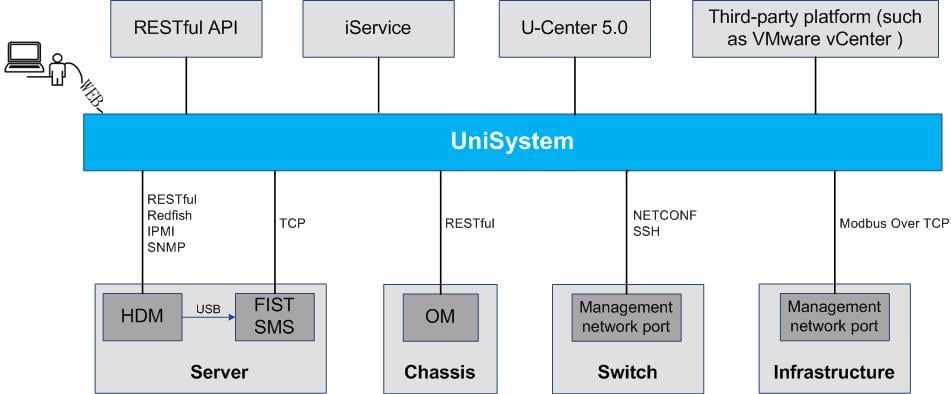
The southbound and northbound connections of UniSystem are as follows:
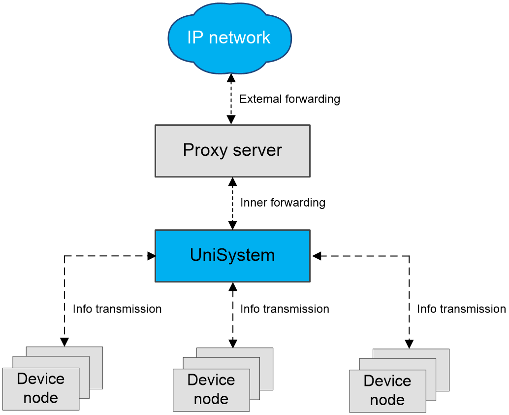
· Northbound—UniSystem adopts a browser-server (BS) architecture, allowing users to perform operations and management on related devices through a browser. It also provides open northbound RESTful API interfaces for third-party integration. Additionally, as shown in Figure 1, UniSystem can serve as a component of other platforms, enhancing their management capabilities.
¡ UniSystem supports integration with iService, acting as a central hub to connect users' servers to H3C's cloud platform.
¡ UniSystem supports integration with U-Center 5.0, functioning as a container component of U-Center 5.0.
¡ UniSystem supports integration with third-party platforms, supplementing their server management capabilities.
· Southbound—UniSystem manages physical devices in the southbound direction and uses the interfaces provided by physical devices to exchange information with devices. Here are the supported interfaces for each type of device:
¡ HDM—Supports RESTful, Redfish, SNMP, and IPMI interfaces.
¡ SMS—Supports TCP interface.
¡ OM—Supports RESTful interface.
¡ Switches—Supports NETCONF and SSH interfaces.
¡ Infrastructure devices such as CDU—Supports Modbus TCP interface.
Benefits
· Cross-platform support—UniSystem supports various deployment installation packages, including VM files, ISO images, installation-free decompressed packages, Docker images (deployed with U-Center, a data center management software developed by H3C), and upgrade files. It meets the installation needs of users in different scenarios, simplifying deployment for operations and maintenance personnel.
· Unified device asset management—UniSystem supports unified management of servers, including Hygon X86, Kunpeng and Phytium. It can simultaneously manage up to 5000 servers, 30 switches, and 128 infrastructure devices. It helps users centrally manage their devices in four dimensions: data centers, server rooms, racks, and device nodes. UniSystem supports obtaining basic device information, performing operations, and inventorying assets on the devices.
· Automated deployment—UniSystem supports various methods for adding servers, including adding a single server, template import, IP range search, automatic discovery, and bulk IP configuration. If servers are deployed, you do not need to perform additional operations as the settings are automatically configured.
· Bulk server deployment—By adopting the distributed image transmission technology based on out-of-band communication of HDM, it ensures the integrity of in-band network resources without being limited by UniSystem network bandwidth. Therefore, it increases the efficiency of operating system installation to more than 10 times that of traditional methods.
· Intelligent version management—UniSystem supports automatic synchronization of REPO firmware versions and compliance checking of firmware/driver versions, improving server version management efficiency.
· Template-based configuration—UniSystem supports HDM configuration templates, BIOS configuration templates, RAID configuration templates, address pool configuration templates, rack server configuration templates, enclosure configuration templates, network configuration templates, interconnect module configuration templates, and switch configuration templates. It can separate the server configuration from hardware, and provides stateless computing.
· Alarm mechanism—UniSystem supports unified management of alarms on servers, alarm suppression policy, alarm redefinition policy, alarm compression policy, and the alarm noise reduction policy. Alarm notifications can be implemented through SNMP, SMTP, WeCom, SMS messages, voice messages, DingTalk, Telegram, and WhatsAPP for users to obtain device alarms in time to reduce service risks.
· One-click retirement—UniSystem supports bulk data clearance for servers. This feature can efficiently reduce the risk of data leakage and ensure service data security when servers are offboarded or transferred.
· Open integration—Provides HTTPS/HTTP-based RESTful APIs, and allows the third-party vendors to integrate UniSystem into users' service processes. This helps users to establish their own maintenance system.
Software compatibility
In some scenarios, UniSystem needs to cooperate with other software products. This section describes the UniSystem compatibility with other software products:
· HDM—HDM is a remote management system (BMC software) developed by H3C to manage servers. UniSystem can cooperate with HDM to implement out-of-band server management.
· FIST SMS—FIST SMS is non-proxy management software installed in the server operating system to enhance HDM and UniSystem management functions. FIST SMS enriches the server management function through in-band communication.
· OM—OM is the software in the onboard management module of the H3C UniServer B16000 enclosure. Through the backplane, the onboard management module is connected to all the other modules in the enclosure to centrally manage and monitor each module in the enclosure. UniSystem can cooperate with OM to manage devices in enclosures.
· REPO—REPO is a component package developed by H3C and is a set of server firmware and drivers.
· iFIST—iFIST is a single-device intelligent deployment software product embedded in servers developed by H3C. In the underlayer, iFIST runs the Linux operating system. Some functions of UniSystem must use iFIST as the operation medium.
· iService—iService is an exclusive intelligent cloud-based service platform tailor-made by H3C for server products. It can assist users in conducting professional basic operation and maintenance management, intelligent risk prevention, and rapid fault handling. In order to meet the user's overall service needs, the iService cloud platform provides a brand-new intelligent delivery experience to guarantee a secure, reliable, and stable operating environment for servers.
· U-Center 5.0—U-Center 5.0 unified O&M platform is data center management software developed by H3C. It is based on an open container base and achieves one-stop management of heterogeneous global mixed resources in the "cloud, network, and edge" domains. The U-Center 5.0 platform has IT resource configuration management as its core capability, and it builds an O&M data center to extract the value of operational data, achieving efficient and unified operations and maintenance.
Features
Fast and flexible management methods
UniSystem supports unified management of H3C servers, switches, enclosure, and infrastructure within the data center.
Manage servers
UniSystem supports unified management of servers. You can add servers to UniSystem through manually adding devices one by one, template import, and IP range-based device discovery, and automatic discovery.
· Manual addition—Add a server to UniSystem through its IP address, username, and password.
· Bulk import—Upload a device information file in .txt, .xls, or .xlsx format to bulk add devices.
· IP range-based device discovery—UniSystem supports discovering servers by using IP ranges. By entering the starting IP address, ending IP address, device username and password, and the number of search cycles, UniSystem can automatically search for relevant server devices. After UniSystem discovers servers, the servers can be added automatically or manually.
· SSDP automatic discovery—UniSystem uses the source IP (link-local address) from the SSDP message to obtain the server's network configuration and automatically adds it to UniSystem for management. The priorities of the dedicated port IPv4 address, dedicated port IPv6 address, shared port IPv4 address, and shared port IPv6 address are in descending order. UniSystem must be on the same Layer 2 network with servers.
The management protocols include Redfish, RESTful, SNMP, and IPMI.
Manage enclosures
UniSystem supports unified management of enclosures. You can only manage enclosures manually. H3C UniServer B16000 servers can be managed, and the management protocol is RESTful.
Manage switches
UniSystem supports unified management of switches. You can only manage enclosures manually. The switches that can be managed include H3C S6800-54QT, H3C S6850-56HF, H3C S6850-56HF-CP, H3C S6850-56HF-IM, H3C S6800-54QF, H3C UIS M8380-C, and H3C UIS M8310. The management protocols are NETCONF and SSH.
Manage infrastructure
Coolant Distribution Unit (CDU) is a crucial device for cooling liquid-cooled servers and an essential component of liquid-cooled data centers. Its main function is to exchange heat between the liquid in the cold plate fluid pipe or immersion tank and the external liquid, thereby efficiently dissipating heat from critical components of the servers.
Build-in template
UniSystem has built-in northbound interface templates for CDU5204 (distributed), ColdPlateCDU (centralized), and ImmersionCDU (immersion), allowing users to manage the devices by entering the device IP and name.
Custom monitoring template
UniSystem supports configuring monitoring templates based on the northbound interface of the infrastructure. It allows importing/exporting templates in XLSX and XLS formats. When adding an infrastructure device, you can bind the infrastructure device to a monitoring template to identify whether the infrastructure device is correctly managed. If the infrastructure device is successfully managed, the monitoring template can be reused when you add other devices from the same vendor.
The infrastructure devices that can be managed include CDU-AAVID-377431-60KW, centralized CDU, immersion CDU, data center environmental monitoring system, rear door heat exchanger, and other devices that use Modbus TCP as the northbound interface. The management protocol is Modbus TCP.
Monitor
Display server information
UniSystem supports displaying information about the components of the managed servers, including:
· Basic information: Device model, serial number, user permissions, health status, primary and backup versions, BIOS version, BIOS boot options, BIOS boot mode, memory (total capacity/number of DIMMs), physical drives (total capacity/number of drives), CPU model, asset tag, UID LED status, power status, power capping status, OS and its version, network details, and leak handling policy (cold plate-based liquid-cooled server).
· Processor information, Total number of supported processors, number of installed processors, health status, PPIN, main frequency, number of cores, number of threads, whether 64-bit is supported, level-1 cache, level-2 cache, and level-3 cache.
· Memory information: Total number of supported DIMMs, number of installed DIMMs, total capacity of memory, health status, location, individual memory capacity, maximum frequency, operating frequency, standard, manufacturer, type, rank, ECC status, manufacturer part number, manufacturer serial number, and operating voltage.
· PCIe information: Slot number, health status, product name, vendor ID, vendor name, device ID, part number, serial number, chip model, maximum rate, negotiated rate, maximum protocol, negotiated protocol, maximum bandwidth, and negotiated bandwidth, riser card, description, and processor.
· Network adapter information: Product name, interface, device vendor, chip vendor, firmware version, health status, slot number, part number, serial number, chip model, port number, port MAC address, network adapter resource, network port resource, maximum rate, negotiated rate, interface type, and connection status.
· Storage controller information: Model, firmware version, package version, serial number, WWN, operating mode, JBOD status, interface type, interface rate, cache capacity, flash card, supercapacitor, and supported RAID levels.
· Logical drive information: Name, status, level, capacity, boot drive, stripe size, read/write policy, I/O policy, physical drive cache policy, access policy, and member drives.
· Physical drive information: Slot number, ID on the BIOS, vendor, model, firmware version, serial number, status, attributes, capacity, remaining life, UID LED status, and hot spare status.
· Power supply information: Total number of supported power supplies, number of installed power supplies, power input power, power supply operating mode, health status, slot number, vendor, model, serial number, firmware version, rated power, input voltage, output voltage, power input mode, and power supply type.
· Fan information: Total number of supported fans, number of installed fans, slot number, health status, model, rotation speed, and rotation speed ratio.
· Firmware information: HDM primary and backup versions, compiling time of HDM primary and backup versions, HDM backup version, compiling time of HDM backup version, BIOS version, ME version, system board CPLD, and iFIST version.
· Temperature sensor information: Front version, rear view, 3D view, 2D view, and temperature of key components.
· Power configuration information: Current total power, power cap value, and power capping policy.
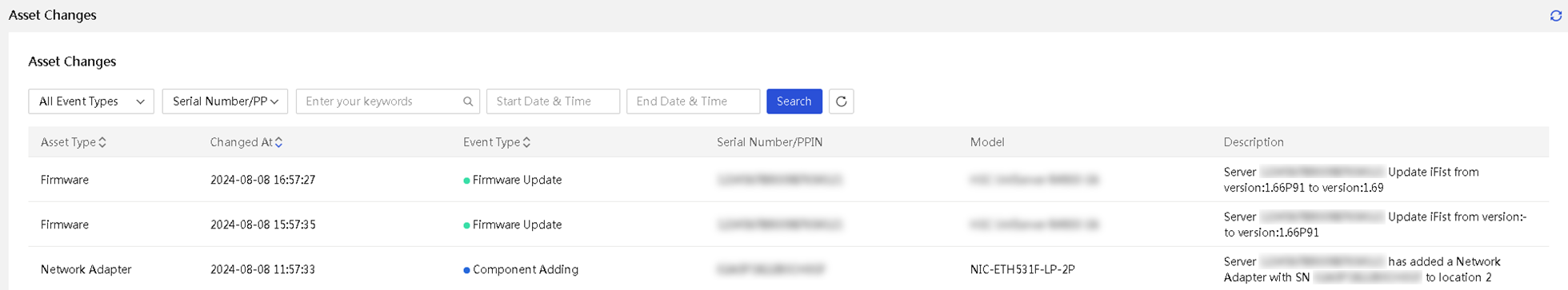
· Asset change information: Records of device deployment, component addition, component removal, and firmware update events.
Server group management
UniSystem supports server group management. Group management helps users categorize devices based on different service scenarios, helping users manage devices more effectively. Depending on the user's use case, UniSystem supports dynamic grouping and static grouping functions. The following grouping methods are supported:
· Static grouping—Allows users to create groups and add devices to these groups.
· Dynamic grouping—Allows users to configure server filtering criteria, and devices that meet the filtering criteria can dynamically join the group.
Dynamic grouping supports the following filtering criteria:
· Devices: Device model, host name, and IPv4 address.
· Processors: Processor mode, main frequency, number of cores, number of threads, and processor status.
· Drives: Drive vendor, drive model, firmware version, status, attributes, transmission rate, and capacity.
· Firmware versions: HDM primary and backup versions, BIOS version, CPLD version, and iFIST version.
Dynamic grouping also supports user-defined combination relationships for the above filtering criteria, including not equal to a certain value, less than a certain value, less than or equal to a certain value, equal to a certain value, greater than a certain value, greater than or equal to a certain value, not null, null, does not contain a certain value, contains a certain value, starts with a certain value, ends with a certain value.
Display switch information
UniSystem supports obtaining the following switch information:
· Switch summary information: Vendor and model.
· Switch card information: Slot number, CPU usage, and memory usage.
· Switch port information: Port name and traffic information.
· Switch interface information: Interface name and state information.
Through UniSystem, you can view the traffic statistics information of switch ports, including:
· Number of received or sent bytes.
· Number of received or sent unicast packets.
· Number of received or sent non-unicast packets.
· Number of received or sent dropped packets.
· Number of received or sent error packets.
· Rate of received or sent bytes.
· Number of received unsupported packets.
Display enclosure information
UniSystem supports obtaining the following enclosure information:
· Basic information: Front view and rear view of the enclosure, enclosure state, subsystem state, OM IP, location, and asset label.
· AE module: Slot number, custom name, product name, management IP, health state, UID LED state, power, air outlet temperature, serial number, manufacture name, CPU info, and memory info.
· Blade server: Slot number, custom name, product name, management IP, health state, UID LED state, power, air outlet temperature, serial number, manufacture name, CPU info, memory info, and node interconnect info.
· OM module: Health state, UID LED state, management IP, slot number, device model, manufacturer, firmware address, serial number, CPU usage, temperature, and system logs.
· Interconnect module: Slot number, health state, and UID LED state, power state, IP address, product name, and CPU usage.
· Power system: Slot number, health state, power redundancy mode, dynamic power saving mode, firmware version, output power, and rated power.
· Fan system: Slot number, health state, firmware version, and rotating speed.
· Power information: Enclosure rated power, available power, power cap, total input power, total output power, real-time power of each enclosure module, and history power trend.
Display infrastructure information
Distributed CDU template
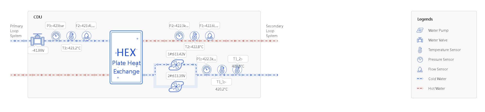
You can obtain information about distributed CDU-template (CDU5204) devices from UniSystem, including:
· Basic information: Device name, health status, device model, device manufacturer, device IP, cooling power, CDU status, description, data center, and equipment room.
· Environmental parameters: Temperature, dew point temperature, relative humidity, dew point upper and lower limits.
· Primary side parameters: FWS inlet pressure (P3), FWS inlet temperature (T3), FWS inlet flow rate (F2), and valve control voltage.
· Secondary side parameters: TCS outlet temperature T1-1, TCS outlet temperature T1-2, TCS inlet temperature (T2), TCS flow rate (F1), TCS outlet pressure (P1), TCS inlet pressure (P2), 1# pump control voltage, and 2# pump control voltage.
· Other parameters: Pump mode, flow rate setpoint, pressure differential setpoint, and temperature setpoint.
· Alarm statistics: Alarm name, status, description, solution, and trigger time.
· Rack management: Associated rack name, location, data center, room, rack size, rack height, and rated power.
Figure 2 CDU5204 summary
Centralized CDU template
You can obtain information about centralized CDU-template (ColdPlateCDU) devices from UniSystem, including:
· Basic information: Device name, health status, device model, device manufacturer, device IP, monitoring template, description, data center, and equipment room.
· Environmental parameters: Electrical conductivity (ED), ambient temperature, ambient humidity, and dew point temperature.
· Primary side parameters: Primary supply water temperature (T1), primary return water temperature (T2), primary supply water pressure (P1), primary return water pressure (P2), primary side outlet flow rate (F1), primary side control valve feedback, and primary control valve opening setting.
· Secondary side parameters: Secondary supply water temperature (T3), secondary outlet water temperature (T4), secondary supply water pressure (P3), secondary return water pressure (P4), secondary side circulating pump inlet pressure (P5), secondary side circulating pump outlet pressure (P6), secondary side filter inlet pressure (P7), secondary side filter outlet pressure (P8), secondary side outlet flow rate (F2), secondary side control valve feedback, secondary supply temperature setting, secondary return temperature setting, secondary supply-return hydraulic differential pressure setting, secondary filter inlet-outlet pressure differential, and secondary control valve opening setting.
· Other parameters: Circulating pump #1 local/remote, circulating pump #1 operating status, circulating pump #1 VFD fault reset, makeup water pump local/remote, makeup water pump running status, unit running indication, unit fault summary, makeup water pump standby, primary control valve manual/auto, secondary control valve manual/auto, circulating pump #1 manual/auto, circulating pump #1 manual start, circulating pump #1 manual stop, makeup water pump manual/auto, makeup water pump manual start, makeup water pump manual stop, CDU primary/backup information, current start/stop status, one-key start, one-key stop, remote reset, makeup water tank liquid level, circulating pump #1 frequency feedback, makeup water pump fixed pressure start/stop deadband, makeup water pump fixed pressure setting, circulating pump #1 frequency setting, unit cooling power, circulating pump #1 continuous running time, circulating pump #1 start time, circulating pump #2 continuous running time, circulating pump #2 start time, CDU rotation cycle, power-on time, CDU rotation cycle setting, Modbus point table version, firmware version, manufacturer, and model.
· Alarm statistics: Sensor name, status, description, solution, and trigger time.
· Rack management: Associated rack name, location, data center, equipment room, rack size, rack height, and rated power.
Immersion CDU template
You can obtain information about immersion CDU-template (ImmersionCDU) devices from UniSystem, including:
· Basic information: Device name, health status, device model, device manufacturer, device IP, monitoring template, description, data center, and equipment room.
· Environmental parameters: Electrical conductivity (ED), ambient temperature, ambient humidity, dew point temperature, Tank-TA liquid level, Tank flow.
· Primary side parameters: Primary supply water temperature (T1), primary return water temperature (T2), primary supply water pressure (P1), primary return water pressure (P2), primary side outlet flow rate (F1), primary control valve opening setting, 1#tank return water temperature, 1#tank supply water temperature.
· Secondary side parameters: Secondary supply water temperature (T3), secondary outlet water temperature (T4), secondary supply water pressure (P3), secondary return water pressure (P4), secondary side outlet flow rate (F2), secondary supply-return pressure differential setting, secondary supply temperature setting, secondary return temperature setting, secondary control valve opening setting.
· Other parameters: Circulating pump #1 local/remote, circulating pump #1 operating status, circulating pump #1 VFD fault reset, primary control valve manual/auto, secondary control valve manual/auto, circulating pump #1 manual/auto, circulating pump #1 manual start, circulating pump #1 manual stop, unit running indication, current start/stop status, one-key start, one-key stop, CDU primary/backup information, circulating pump inlet pressure (P5), circulating pump outlet pressure (P6), filter inlet pressure (P7), filter outlet pressure (P8), circulating pump #1 frequency feedback, circulating pump #1 frequency setting, unit cooling power, circulating pump continuous running time, circulating pump start time, CDU rotation cycle, unfiltered time, filtered duration, power-on time, Modbus point table version, firmware version, manufacturer, and model.
· Alarm statistics: Sensor name, status, description, solution, and trigger time.
· Rack management: Associated rack name, location, data center, equipment room, rack size, rack height, and rated power.
Data center environmental monitoring system
You can obtain information about the data center environmental monitoring system device, including:
· Basic information: Device name, health status, device model, device manufacturer, device IP, monitoring template, description, data center, and equipment room.
· Leak handling policy: Leak alarm location and solenoid valve policy.
· Intelligent temperature control policy: intelligent temperature control status, solenoid valve opening setting.
· Alarm statistics: Sensor name, status, description, solution, and trigger time.
Display data center information
UniSystem supports data center management, allowing you to monitor power supply and device distribution within the data center.
Data center
UniSystem supports manually adding data centers and viewing details, including data center name, number of rooms, number of racks, number of devices, and details of affiliated rooms.
Equipment room
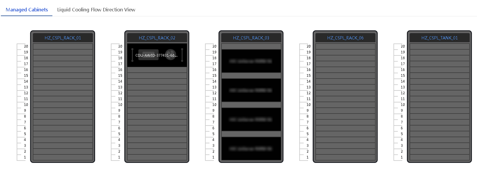
UniSystem supports adding rooms within data centers and viewing room details, including room name, affiliated data center, room size, rack orientation, number of racks, number of devices, affiliated racks, and liquid cooling flow direction view.
The affiliated racks display the distribution of devices within the room and allow for checking the health and temperature status of the devices.
Figure 3 Racks in the equipment room
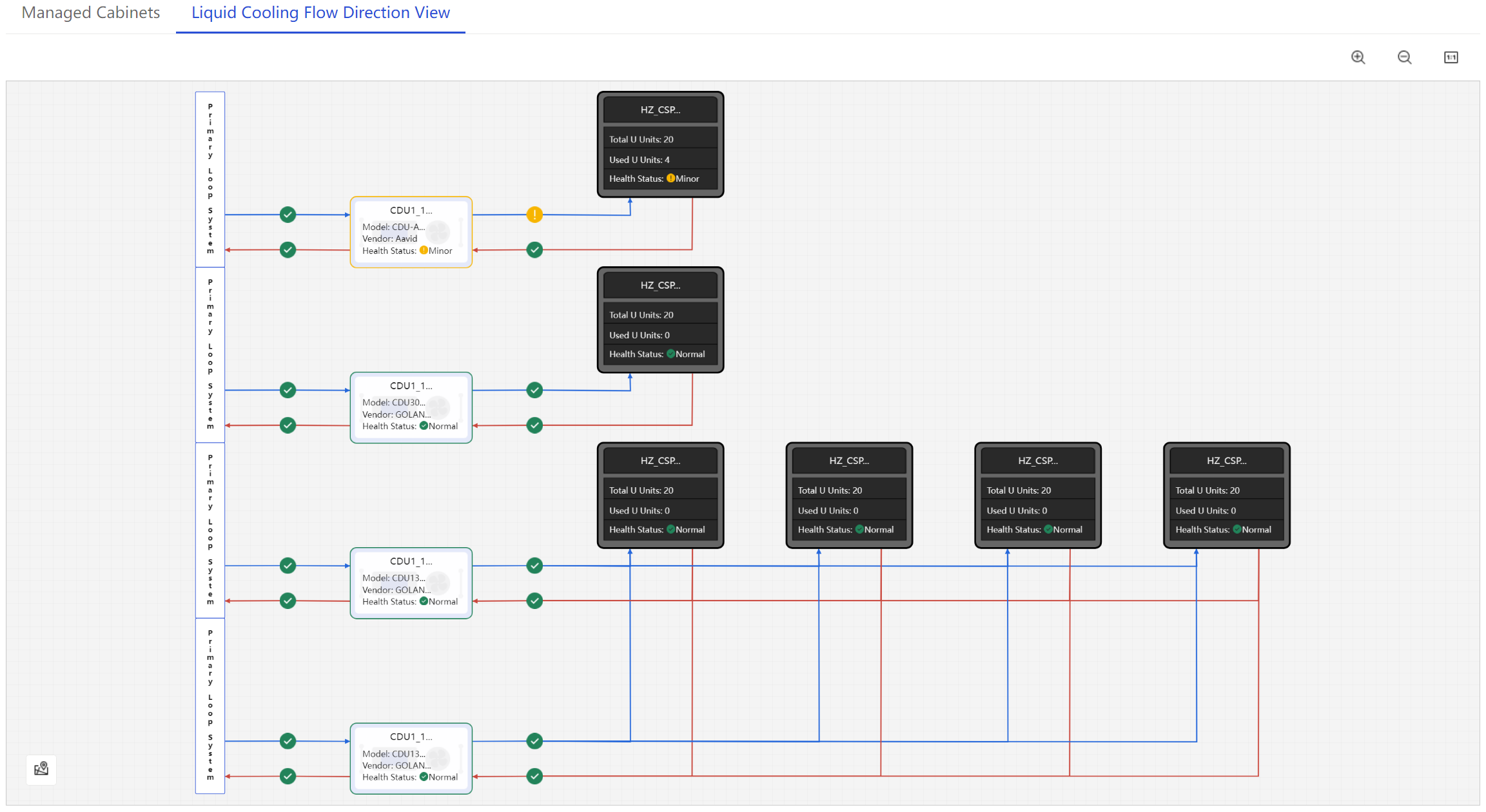
The liquid cooling flow direction view displays the liquid flow path between the infrastructure and racks/TANK, providing access to the following information:
· Infrastructure summary.
· Rack/TANK summary.
· Sensor information and alarms for primary and secondary side inlet and return water pipelines.
Figure 4 Liquid cooling flow direction view
Rack
UniSystem supports adding common racks and immersion racks (TANK) within rooms, and viewing rack details, including rack name, type, location, equipment room, data center, size, height, rated power, description, rack details, and associated infrastructure list.
Table 1 Rack types
|
Rack type |
Managed device type |
Bindable CDU type |
|
Common rack |
Server, switch, distributed CDU, data center environmental monitoring system, and custom device |
Distributed CDU and centralized CDU |
|
Immersion rack (TANK) |
Immersion server, immersion switch, and custom device |
Immersion CDU |
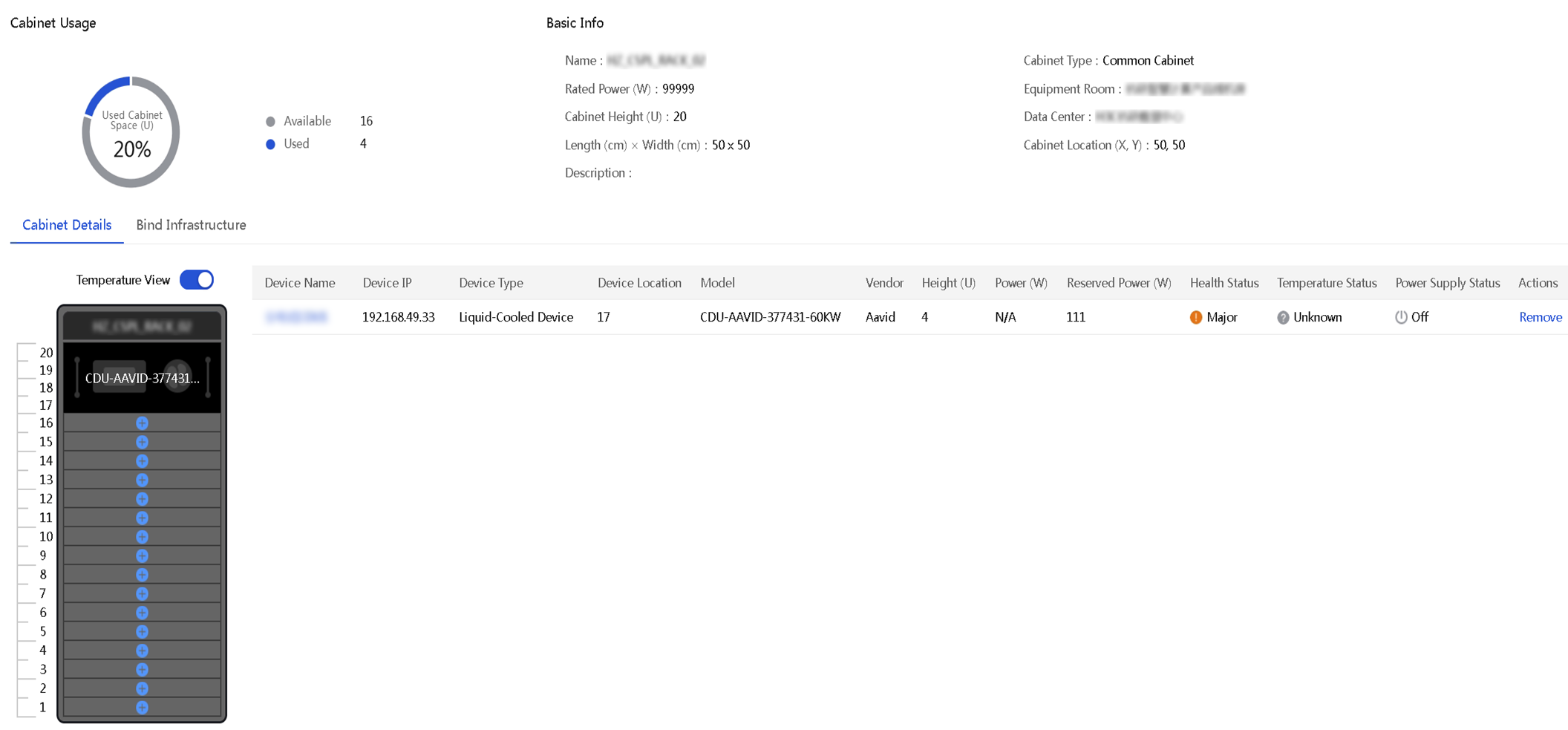
You can obtain rack physical view and temperature view in the rack details, enabling multi-dimensional real-time monitoring of the rack status.
Figure 5 Rack physical view
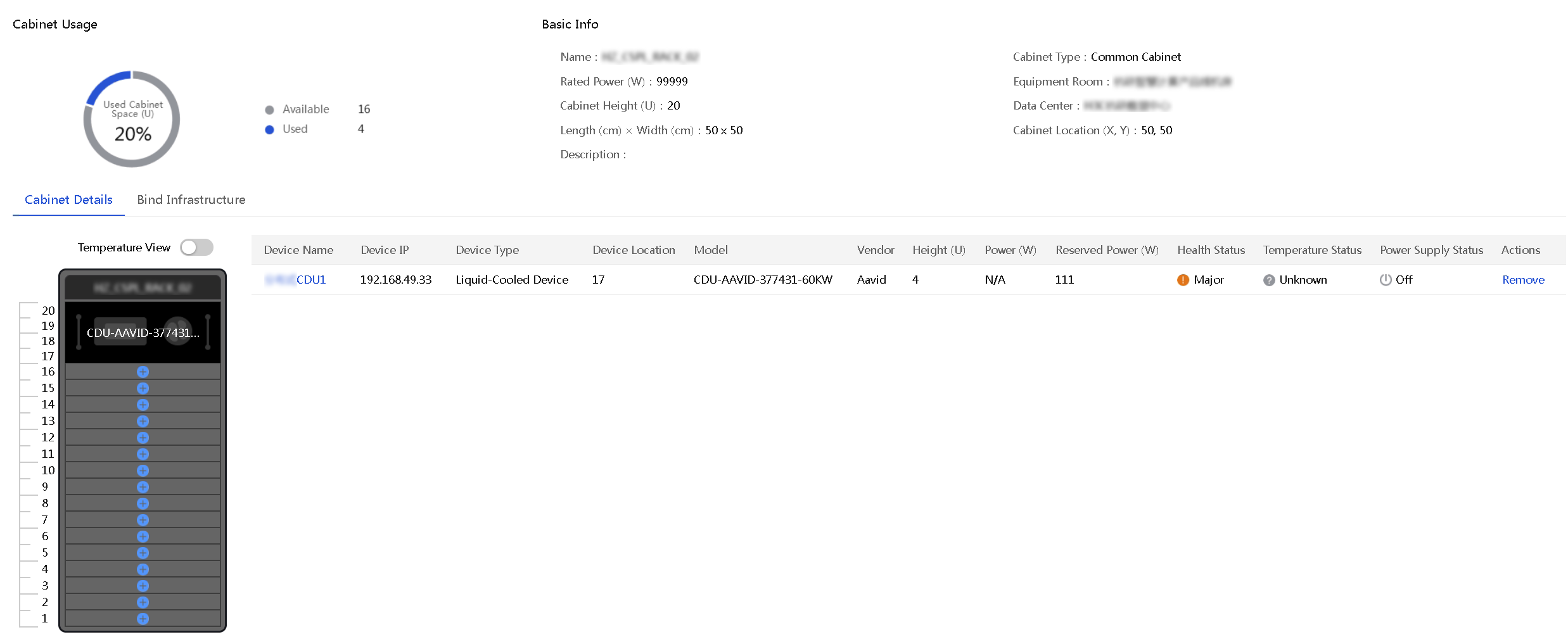
Figure 6 Rack temperature view
Alarm management
Device alarm management
UniSystem supports centralized display, query, suppression, compression, noise reduction, redefinition policies of device alarms. Alarm notifications can be delivered through email, SMS messages, voice messages, WeCom, DingTalk, Telegram, WhatsApp, and SNMP policies, enabling centralized management and prompt response to alarms.
Table 2 Alarm functions
|
Alarm functions |
Description |
|
Alarm display |
Monitor device status in real time through the alarm panel and alarm list. |
|
Alarm suppression |
Suppress the non-critical alarms for specific events through custom rules to reduce interference. |
|
Alarm compression |
Aggregate all alarms of the same type from managed servers into a single alarm to reduce redundant alarms. |
|
Alarm noise reduction |
Forward an alarm message only when the number of triggers reaches the noise reduction threshold to minimize irrelevant or redundant alarms. |
|
Alarm redefinition |
Redefine the alarm severity to achieve flexible change between alarms and events. |
|
Alarm notification |
Support real-time notification of alarm messages to O&M personnel via email, WeCom, DingTalk, Telegram, WhatsAPP, SMS, and voice, according to customized content templates. |
|
Alarm forwarding |
Support reporting server faults to a user-specified SNMP server via SNMP trap, with support for protocols including v1, v2c, and v3. |
|
Alarm voice |
Trigger an alarm voice when it receives an alarm of the specified severity level. |
Audit logs
UniSystem supports unified management of system logs and event logs. This comprehensive log management method provides effective assistance for daily operation and maintenance and log audit.
Table 3 Audit logs
|
Function type |
Description |
|
Log configuration |
Configure the Syslog server address to upload the server event logs in real-time to a third-party log management server. |
|
Log query |
Quickly filter out the target logs based on the source, severity and time. |
|
Log export |
Download all operation logs and running logs to the device to make it convenient for users to generate reports and conduct analysis. |
Performance monitoring
UniSystem monitors key components of servers such as CPU, GPU, memory, drive, network adapter, sensor, and power supply, providing real-time and historical performance analysis and visualization. In addition, UniSystem has integrated the Holt-Winters time series forecasting algorithm to help analyze and predict service resource bottlenecks, effectively evaluating resource usage, and optimizing device performance.
|
|
NOTE: FIST SMS is required for all types of statistics except temperature statistics and power statistics. |
Table 4 Performance monitoring statistics
|
Statistics type |
Description |
|
CPU |
CPU usage, CPU usage prediction |
|
GPU |
GPU usage |
|
Memory |
Memory usage, cache memory size, memory usage prediction, cache memory size prediction |
|
Disk |
Disk usage, disk I/O, disk throughput, disk read/write ratio, disk queue depth, disk I/O latency, slow disk detection |
|
Network |
Transmit rate, receive rate. |
|
NFS |
NFS client read/write rate, NFS server read/write rate |
|
System load |
System load within one minute, five minutes, and 15 minutes. |
|
Temperature |
Air inlet temperature |
|
Power |
Current power of the server |
Intelligent deployment management
Server configuration template
The server configuration template separates configuration of the server from server hardware to logically virtualize physical servers. The template includes HDM, BIOS, connection, RAID, system, and firmware baseline configurations. It also supports bulk application and can be imported to other devices. This enables flexible changes to server configurations and increases the efficiency of faulty device repairing and server hardware expansion.
UniSystem supports server configuration template management functions, including: creating, importing, exporting, applying, editing, copying, and deleting functions.
Table 5 Server configuration template functions
|
Function |
Description |
|
Creating |
Supports creating configuration templates for different device models, including template name, description, HDM settings, BIOS settings, connection settings, RAID settings, system settings, firmware repository settings |
|
Importing |
Support manual import of HDM, BIOS, and RAID configuration templates |
|
Exporting |
Support export of HDM, BIOS, and RAID settings |
|
Applying |
Support bulk applying a server configuration template to servers. Both immediate, scheduled and cyclic application is available |
|
Editing |
Support editing settings in a server configuration template |
|
Copying |
Support copying a server configuration template, allowing for renaming of template name and description. Online modifications can be made based on this configuration template |
|
Deleting |
Support deleting server configuration templates |
HDM settings
Server configuration templates support HDM settings. You can configure HDM settings in the following methods:
· Selecting a template: You can import an HDM configuration template or export HDM configuration templates from other servers.
· Online configuration: You can configure HDM settings online including user management, NTP, SNMP, SMTP, SNMP trap, and syslog settings.
BIOS configuration
Server configuration templates support BIOS settings. You can configure BIOS settings in the following methods:
· Selecting a template: You can import a BIOS configuration template or export BIOS configuration templates from other servers.
· Online configuration: You can configure BIOS settings online including Main, Main, Advanced, Server, Security, and Boot settings.
RAID configuration
The server configuration template supports RAID settings. When a storage controller supports out-of-band RAID configuration, UniSystem uses the HDM API for RAID configuration. If a storage controller card does not support out-of-band RAID configuration, UniSystem controls the server to boot from iFIST and sends RAID configuration information to iFIST.
RAID configuration functions include the following:
· Bulk completion of RAID creation and configuration for the same hardware.
· Support for deletion, retention of original RAID, and other scenario requirements.
· Support for one-click creation of RAID 0.
Table 6 Supported storage controllers
|
Vendor |
Storage controller model |
|
LSI |
RAID-LSI-9460-16i(4G) |
|
RAID-LSI-9460-8i(2/4G) |
|
|
RAID-P5408-Mf-8i-4G |
|
|
RAID-P5408-MA-8i-4G |
|
|
RAID-L460-M4 |
|
|
HBA-LSI-9440-8i |
|
|
HBA-H5408-Mf-8i |
|
|
RAID-LSI-9361-8i(1/2G)-A1-X |
|
|
HBA-LSI-9400-16i |
|
|
HBA-LSI-9400-8i |
|
|
RAID-LSI-9560-LP-16i-8GB |
|
|
RAID-LSI-9560-LP-8i-4GB |
|
|
HBA-LSI-9500-LP-8i |
|
|
HBA-LSI-9500-LP-16i |
|
|
HBA-LSI-9500-16e |
|
|
HBA-LSI-9540-LP-8i |
|
|
HBA-LSI-9311-8i-A1-X |
|
|
HBA-LSI-9300-8i-A1-X |
|
|
PMC |
RAID-P430-M1/2 |
|
HBA-1000-M2-1 |
|
|
RAID-P2404-Mf-4i-2GB |
|
|
RAID-P4408-Mf/Ma-8i-2GB |
|
|
HBA-H460-M1 |
|
|
HBA-H460-B1 |
|
|
RAID-P460-M2 |
|
|
RAID-P460-B2 |
|
|
RAID-P460-M4 |
|
|
RAID-P460-B4 |
|
|
RAID-P460-B/M4 |
|
|
HBA-H460-B/M1 |
Connection settings
The server configuration template supports connection settings. It allows the creation of network transmission pathways from a rack server's system application to the switch's downstream ports, as well as from a blade server's system application to the interconnect module's upstream ports, and enables rapid service switching.
Table 7 Connection settings
|
Server type |
Description |
|
Rack server |
Configure the switch port VLAN. |
|
Blade server |
Configure the network mode, port speed, VLAN ID, and other parameters for the downstream and upstream ports of the mezzanine card and interconnect module. |
System settings
The server configuration template supports system settings, and allows operating system installation through image or cloning. The automatic installation of images is achieved by customizing the operating system's auto-installation script, such as by customizing the ks.cfg file for Linux and the Unattend.xml file for Windows.
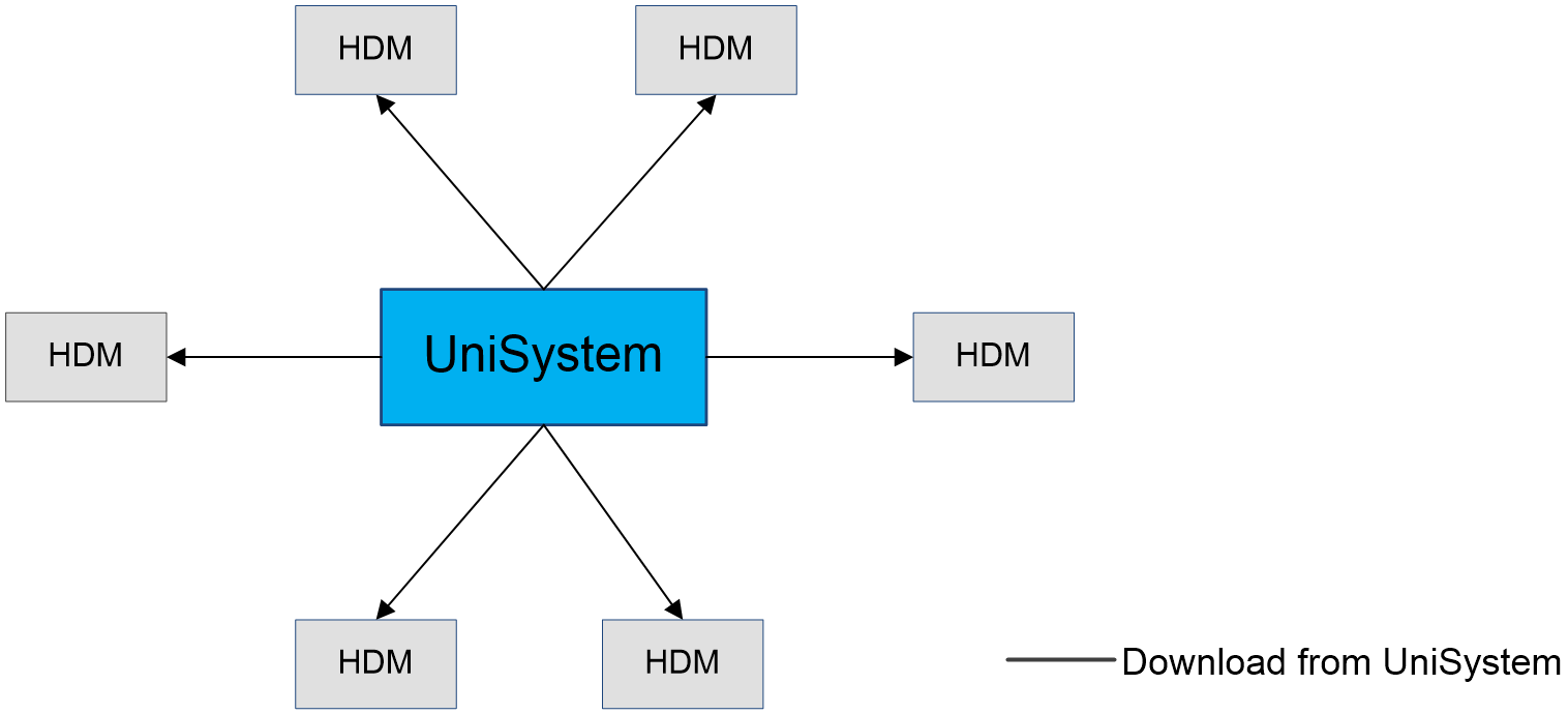
· OS installation with universal image: UniSystem mounts the operating system image onto servers via KVM, with UniSystem acting as the image information source. At this time, UniSystem's network bandwidth becomes the bottleneck for the operating system installation. When the bandwidth is high, the transmission is fast, and thus the installation is quick. Otherwise, the installation is slow.
Figure 7 OS installation with universal image
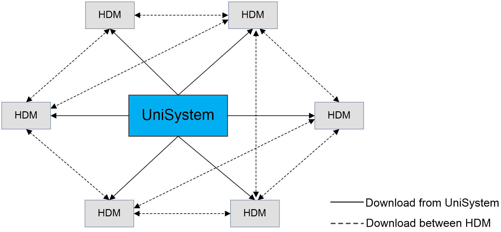
· Distributed bulk OS installation: With out-of-band distributed image transmission of HDM, both UniSystem and the target server's HDM can be used as image sources. When one HDM has a fragment of the image, other HDMs can obtain this image fragment not only from UniSystem but also from that HDM. Therefore, the network bandwidth of UniSystem will not become a bottleneck, making it especially suitable for scenarios involving mass server operating system installations.
Figure 8 Distributed bulk OS installation
· Cloned OS installation: Use UniSystem to control the target server to enter iFIST, use iFIST to partition the target disk, and then copy the boot and operating system files to the corresponding partitions. Cloning installation can save users time from reinstalling applications and drivers.
· To ensure the security of service data, UniSystem allows customers to select the target disk during OS parameter configuration, including logical or physical disks, to prevent data loss from installing the OS on a data disk. UniSystem does not require users to configure the boot disk in advance in the RAID configuration, reducing the complexity of operations and the possibility of errors for customers.
|
|
NOTE: · Image installation and cloning allow specifying the operating system's installation disk to prevent the system from being installed on the user's data disk, thus avoiding loss of user data. · The ks.cfg file is for the automatic installation of Linux systems, where you can configure parameters such as username and password. The ks.cfg file follows a detailed set of syntax specifications. For more information, see the documentation provided by the operating system manufacturer. · The Unattend.xml file is used for the automatic installation of Windows systems, functioning similarly to ks.cfg. · Clone installation requires an in-band network and interoperability of UniSystem and iFIST IP addresses. |
Firmware baseline configuration
The server configuration template allows the selection of a firmware baseline configuration, which refers to the REPO LiveCD image. Servers applied with this template use the firmware from this image as a baseline. If a server's firmware version is lower than the version in the image file, this feature can help customers quickly update their firmware to the version in the REPO baseline.
Driver installation
The server configuration template supports driver installation, which means users can opt to install certain drivers after the operating system installation via image, saving time on driver updates post-deployment.
|
|
NOTE: Driver installation requires cooperation with the operating system installation and is only supported when the user opts for a fresh installation through an operating system image. |
Image management
Image management supports the management of the following images: operating system images, diskless boot volumes, and cloned installation image packages. The images managed by UniSystem, combined with server configuration templates, can implement the operating system installation function for servers.
Operating system image
UniSystem supports the upload, deletion, categorization, download, and display of image names, image versions, image types, and image sizes.
Table 8 Supports image types
|
Image type |
Image version number |
|
RHEL |
RHEL 6U*, RHEL 7U*, RHEL 8U*, RHEL 9U* |
|
VMware |
ESXi 6.5, ESXi 6.7, ESXi 7.0, ESXi 8.0 |
|
SLES |
SLES 11SP4, SLES 12*, SLES 15* |
|
Centos |
CentOS 6U10, CentOS 7U*, CentOS 8U* |
|
Windows |
Windows 2012_R2, Windows 2016, Windows 2019, Windows 2022 |
|
Ubuntu |
Ubuntu 17.10*, Ubuntu 18.04*, Ubuntu 20.04.*, Ubuntu 22.04.* |
|
Kylin |
KylinLinux V10-SP* |
|
CAS |
CAS-E0513, CAS-E0526, CAS-E0782 |
|
Oracle Linux |
Oracle Linux 8*, Oracle Linux 9.* |
|
Rocky Linux |
Rocky Linux 8.*, Rocky Linux 9.* |
|
OpenEuler |
OpenEuler 20.03 LTS-*, OpenEuler 22.03 LTS-* |
|
NingOS |
NingOS V3.1.0.* |
Diskless boot volume
Diskless boot refers to a server having its operating system installed remotely, and retrieving system files from a remote location during startup. A volume refers to an image file stored under the AE. Blade servers install the operating system onto the AE's built-in drive via the iSCSI protocol and support booting from this volume file through the iSCSI protocol.
UniSystem supports creating, deleting, copying, displaying names, displaying sizes, showing connection status, showing description information, and showing authentication information.
Image package for clone installation
Clone installation refers to the technology of directly cloning an operating system from one server to another, supporting the cloning of not only the operating system but also applications and drivers. UniSystem sends commands to operate the server booting from iFIST, and once iFIST starts, running the related scripts to export the operating system files. The exported operating system files are packaged into an image archive and saved on the UniSystem server through Samba software.
UniSystem supports exporting, deleting, and viewing information such as image names, image types, and image sizes.
Table 9 Image types that support cloning
|
Image type |
Image version number |
|
RHEL |
RHEL 7U*, RHEL 8U* |
|
VMware |
ESXi 6.5, ESXi 6.7, ESXi 7.0 |
|
CentOS |
CentOS 7U4, CentOS 7U5, CentOS 7U6 |
Automatic planning and onboarding
UniSystem supports switch port association with server configuration templates. When a server's dedicated port connects to a switch port, it automatically incorporates the server into UniSystem and applies the configuration template, achieving stateless configuration of the rack server.
REPO baseline
Add a baseline
UniSystem supports adding baselines from UNC path, HTTP server path, and local path. HTTP server path communicates via the HTTP protocol, while UNC path uses the SMB protocol.
Inventory baselines
UniSystem supports inventory of added baselines, including component name, description, version, update method (HDM or FIST SMS), and whether a restart is required for it to take effect.
Custom baseline repository
UniSystem supports the creation of custom baselines. To create a custom baseline, users must first add a standard baseline repository, then select filtering criteria to choose the required components. UniSystem will automatically package the selected components into a custom baseline repository. Custom baselines are smaller and easier to transfer, enhancing the flexibility and accuracy of operational maintenance work.
In addition to the UniSystem software supporting customization of the baseline repository, users can also customize baselines within the REPO remote system.
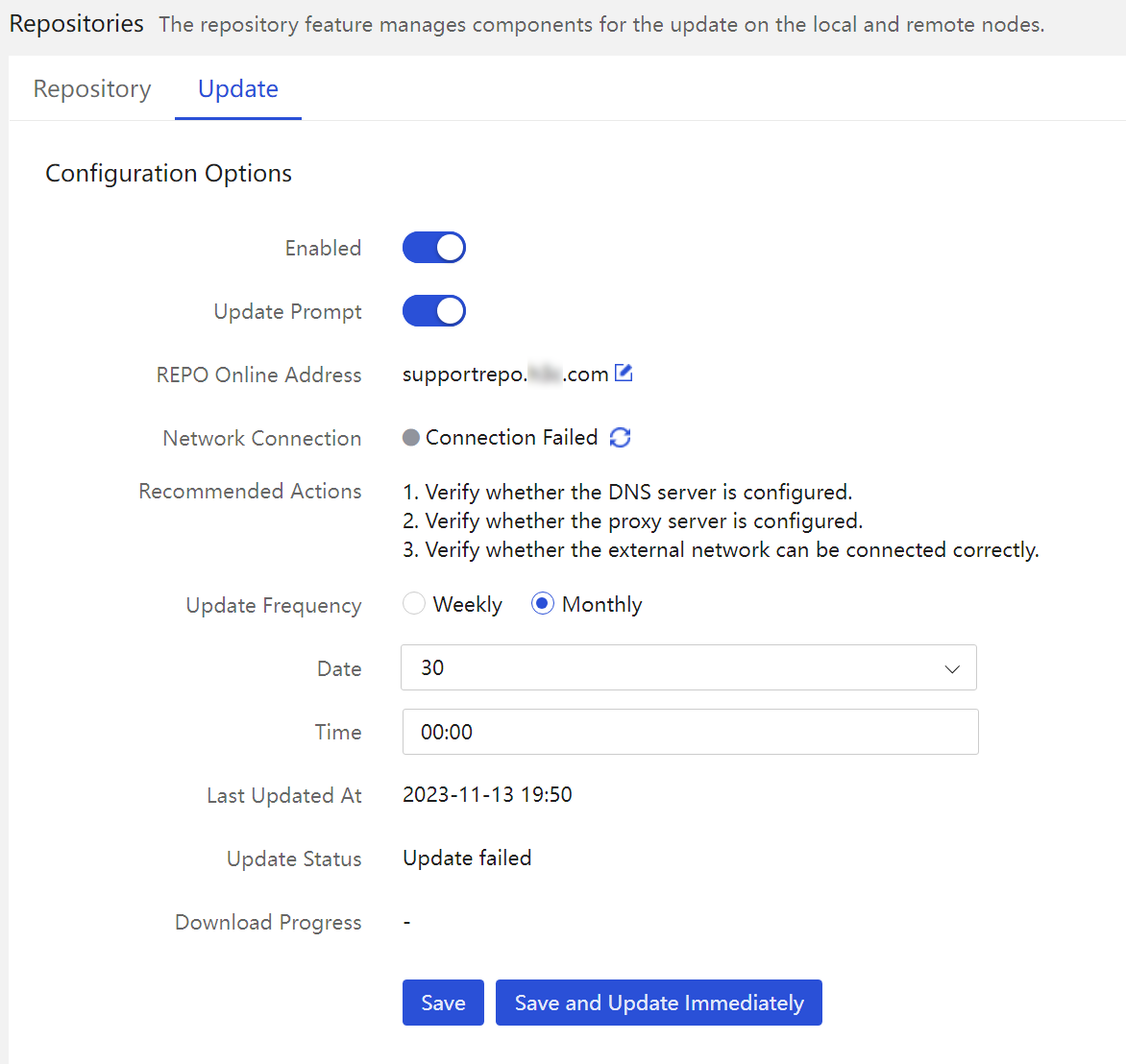
Baseline update
UniSystem supports the online synchronization feature with baseline timing. When connected to the remote REPO system, UniSystem actively synchronizes the firmware and drivers, alerting the user to version updates. The server configuration template in UniSystem allows for automatic firmware updates at scheduled times. This feature protects servers for worry-free operation, effectively improving data center management efficiency and reducing labor costs.
Figure 9 Baseline update configuration
Component update
Components refer to the collective term for hardware drivers and firmware on a server. The component update feature is used to update the versions of related firmware and drivers on the server, supporting the following functions:
· Supported component types include: HDM, BIOS, CPLD, Option card firmware and drivers, and drive firmware.
· The system automatically compares the component versions in the baseline package with those installed on the server and recommends installation when the baseline package version is higher.
· It supports downgrading, updating the same version, and upgrading.
The advantages of component updates are as follows:
· FIST SMS enables updating the drivers and firmware of server operating systems.
· Customizing the existing baseline repository is possible, such as creating customized baselines to enhance operational flexibility and accuracy.
· Batch updates improve operational efficiency and reduce maintenance costs.
· It covers a variety of use cases, essentially meeting all user needs.
Table 10 Application scenarios
|
Scenario |
Description |
|
Single package upgrade |
Support the use of each individual driver or firmware package for upgrades (drive firmware relies on repository tools). |
|
Out-of-band firmware update |
Support firmware updates for servers via HDM out-of-band. |
|
REPO LiveCD |
Support updating the firmware of the server after booting the built-in subsystem. |
|
Driver update |
Support updating system drivers through FIST SMS and synchronizing driver updates during operating system deployment. |
UniSystem supports updating firmware/drivers for one or multiple servers simultaneously, with various methods such as component update, HDM out-of-band firmware update, offline firmware update, and automatic driver installation. These features facilitate bulk repair of patch vulnerabilities or upgrading HDM, BIOS, CPLD, option cards, and drive firmware/drivers.
· Component update: Includes both out-of-band and in-band methods.
¡ Out-of-band method: UniSystem updates firmware by calling HDM's RESTful or Redfish interfaces. This method supports firmware updates for HDM, BIOS, CPLD, and option cards, and allows setting the effective time for deployment and whether to retain configuration during the upgrade.
¡ In-band method: UniSystem sends the component package to the server operating system via the TCP protocol, where FIST SMS performs the component update operation. This method supports updates for HDM, BIOS, CPLD, Option card firmware and drivers, and drive firmware.
· Out-of-band firmware update for HDM: Suitable for scenarios where the server cannot be immediately restarted and only an out-of-band network is available. UniSystem uploads the REPO image to HDM for storage. Upon the next server reboot, it will automatically enter iFIST, which will then perform firmware updates for the server, supporting updates for Option cards and drive firmware.
· Offline firmware update: Suitable for servers without an operating system installed or when out-of-band firmware update capabilities cannot fully cover the firmware that needs upgrading. UniSystem mounts the Live CD image of REPO onto the server that needs upgrading through KVM, then controls the server to boot from this image and automatically invokes the upgrade script to complete the firmware update. The method supports updates for HDM, BIOS, CPLD, Option card firmware, and drive firmware.
· Automatic driver installation refers to the installation of selected drivers concurrently with the operating system installation through UniSystem, requiring the concurrent use of iFIST and REPO with UniSystem. For more information about automatic driver installation, see "Driver installation."
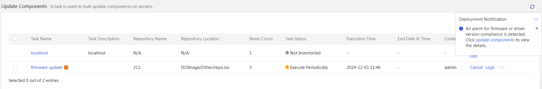
Compliance check
UniSystem supports compliance monitoring of firmware/drivers, and baseline offset reminders. UniSystem monitors differences in firmware/driver versions of devices and the baseline library by creating periodic tasks. It generates alarms or initiates automatic upgrades to higher versions for the tasks with deviations.
Figure 10 Firmware compliance alarms
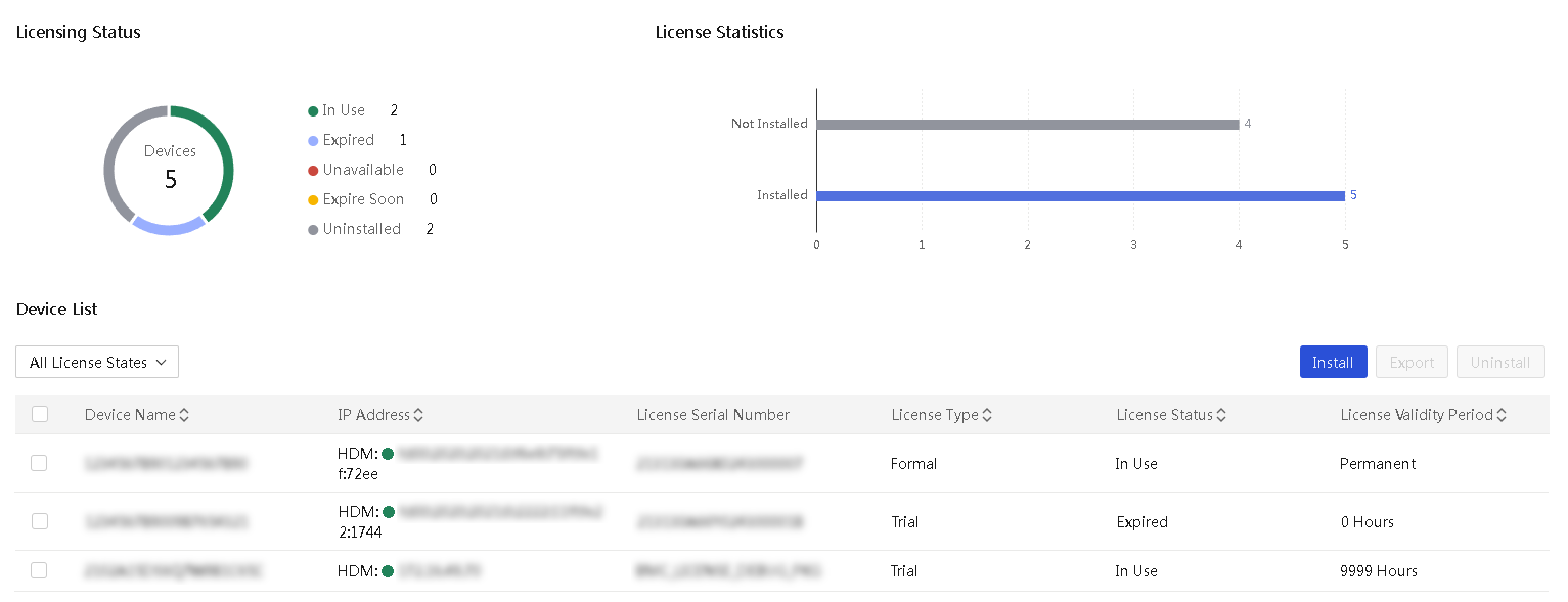
Software license management
UniSystem supports batch management of HDM licenses, enabling users to view, export, install, and uninstall licenses.
Figure 11 Software license management
Intelligent optimization
Batch IP configuration
UniSystem supports uploading IP configuration templates to batch modify server IPs, effectively saving server rack time.
Batch modification of IP supports the following modes:
· Through the original IP address: This mode is suitable for IP migration scenarios and supports batch migration of a server cluster's original IP range to a new IP segment.
· Change the MAC address through the network port: This mode is suitable for IP migration scenarios and new server deployment scenarios. Users need to input the MAC address of the server's network port, and UniSystem can calculate the corresponding Link-Local address based on the network port's MAC address.
· Modify through the SN number: This mode is suitable for newly deployed servers, where the user must enter the server's SN number.
¡ UniSystem continuously probes the device at 192.168.1.2 in the layer 2 network to retrieve the device's SN number and Link-Local address. If the device's SN is in the uploaded configuration template, UniSystem will distribute the user's network configuration to the corresponding server through the Link-Local address.
¡ The server initiates the SSDP service, which periodically sends SSDP messages within the Layer 2 network, and these messages contain the device's SN number and source IP. If the device's serial number is in the uploaded configuration template, UniSystem will distribute the user's network configuration to the corresponding server through the source address of the SSDP packet.
|
|
NOTE: The server's network port must be within the same Layer 2 network as the UniSystem, and the IPv6 of the network port must be enabled. |
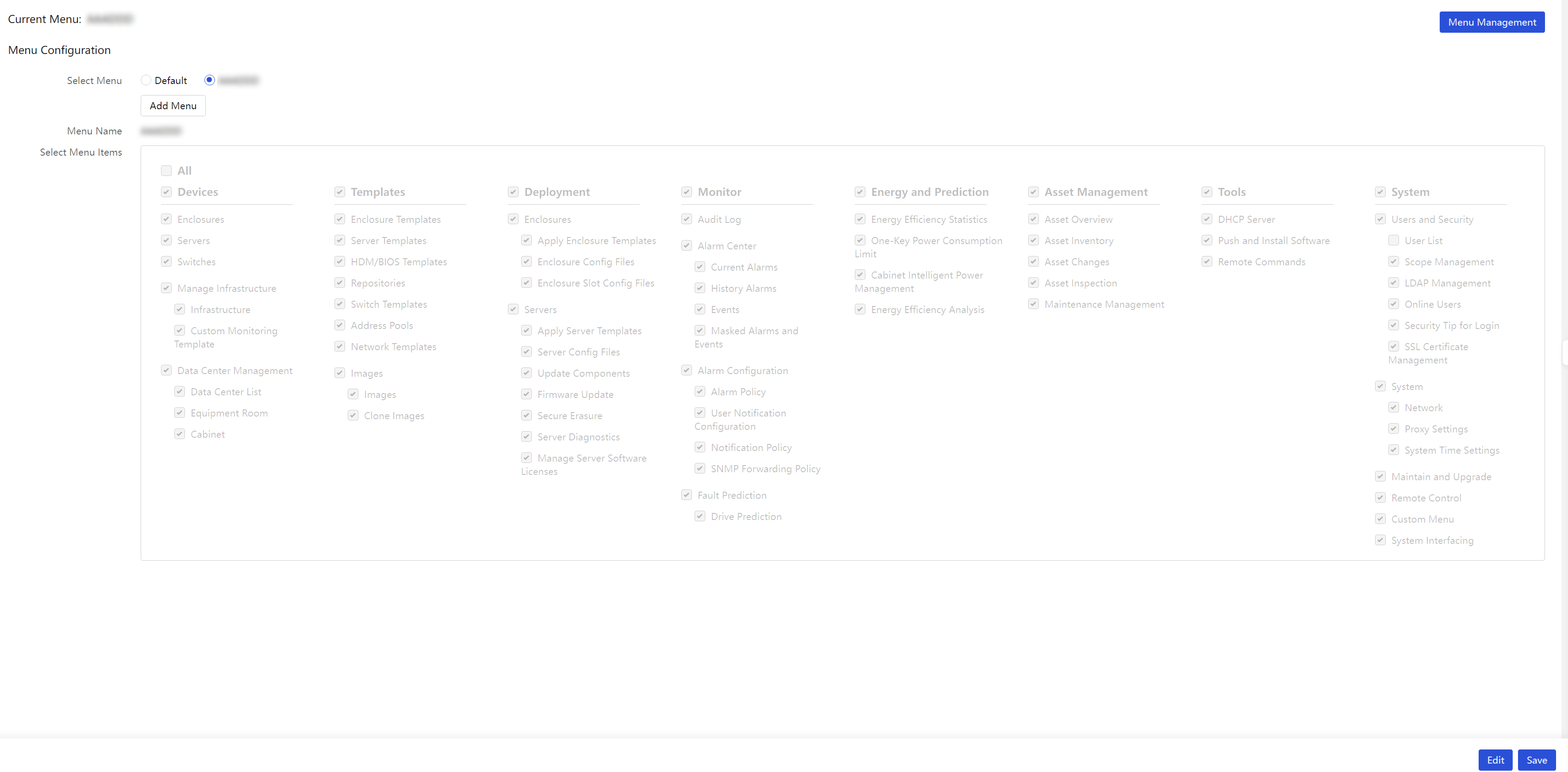
Create a custom menu
UniSystem supports building custom menu schemes that ensure the top menu bar display matches the user-selected menu items by deploying these schemes.
Figure 12 Custom menu page
Intelligent energy-saving
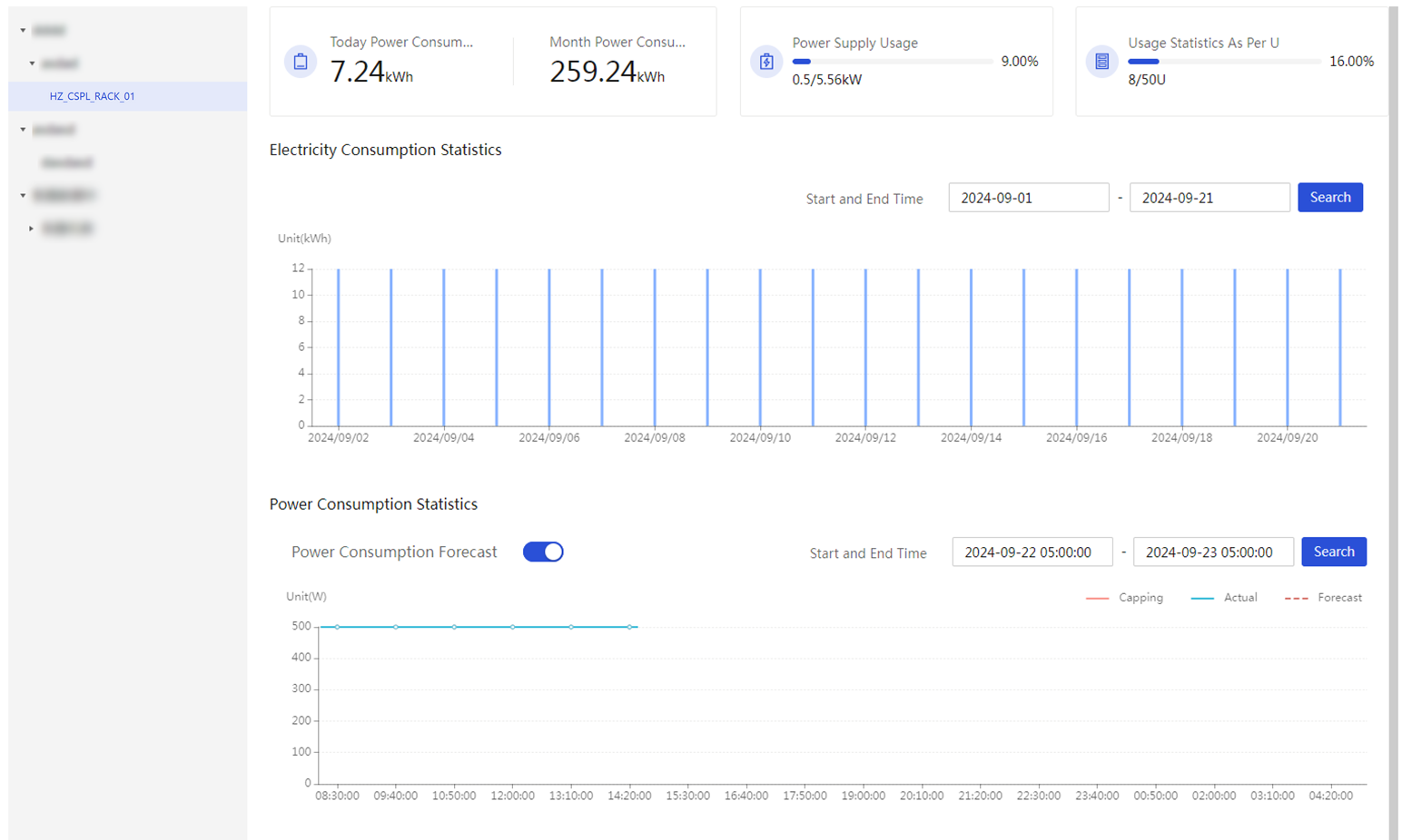
Energy efficiency statistics
Energy efficiency statistics gather data on daily and monthly power consumptions, power usage rates, U-space utilization rates, electricity usage statistics, power consumption statistics, top 5 power-consuming devices, and Top 5 U-space occupancy rates from the perspectives of data centers, computer rooms, and racks. It also uses AI power prediction algorithms to forecast power consumption across various dimensions.
Figure 13 Energy efficiency statistics
One-key emergency power consumption
The one-key emergency power consumption feature is mainly used when there is a failure in the power supply system of a server room, and the emergency power source either kicks in or is about to. The main purpose of this feature is to extend the usage time of services.
UniSystem supports the following one-key emergency power consumption policies:
· Enabled: The policy is enabled or disabled.
· Emergency power consumption strategy: The policy supports three strategies, including shutdown, minimum power consumption, and customization.
¡ Shutdown: When users issue this strategy, these servers will undergo a shutdown process.
¡ Minimum power consumption: When users issue this strategy, these servers will cap power according to the lowest power consumption of the last day.
¡ Customization: When users issue issue this strategy, these servers will cap power based on customized values Users can also set the effective time for the strategy and configure whether to shut down the server when its power exceeds the limit.
· Restrictions: This feature is applicable to G6 and later servers in the cabinet.
Intelligent power consumption management for cabinets
UniSystem supports dynamic power capping for cabinets, which includes:
· Power capping policy: The current power capping policy includes dynamic and off options.
· Power cap: Power limit for the entire cabinet. UniSystem integrates an AI power prediction algorithm to dynamically allocate server cap power.
· Effective time: The power cap setting takes effect at different times, including immediate, delayed, cyclical, and time period options.
· Restrictions: This feature is applicable to G6 servers in the cabinet.
Energy efficiency analysis
Energy efficiency analysis primarily examines the environment, power supply, rack U-space, and server usage in data centers, helping users enhance equipment usage and thus improve data center energy efficiency.
Advanced settings
Advanced settings are for configuring energy efficiency analysis parameters and include:
· Air inlet temperature analysis: Air inlet temperature status, temperature range, overtemperature count threshold, low-temperature count threshold, and duration.
· Cabinet space analysis: Cabinet space analysis status, and cabinet usage range.
· Power supply analysis: Power supply analysis status, power supply ratio range, high power supply count threshold, low power supply count threshold, and duration.
· Server usage analysis: Server usage analysis status, CPU usage range, GPU usage range, memory usage range, and duration.
Air inlet temperature analysis
Inlet temperature analysis involves examining the server inlet temperatures within a data center, displaying pie charts of server temperature status distribution, lists of servers with abnormal temperatures, and the number of high and low temperature alarms generated during an analysis period. Users can choose from various temperature specifications according to their usage scenarios, including:
Figure 14 Air inlet temperature analysis
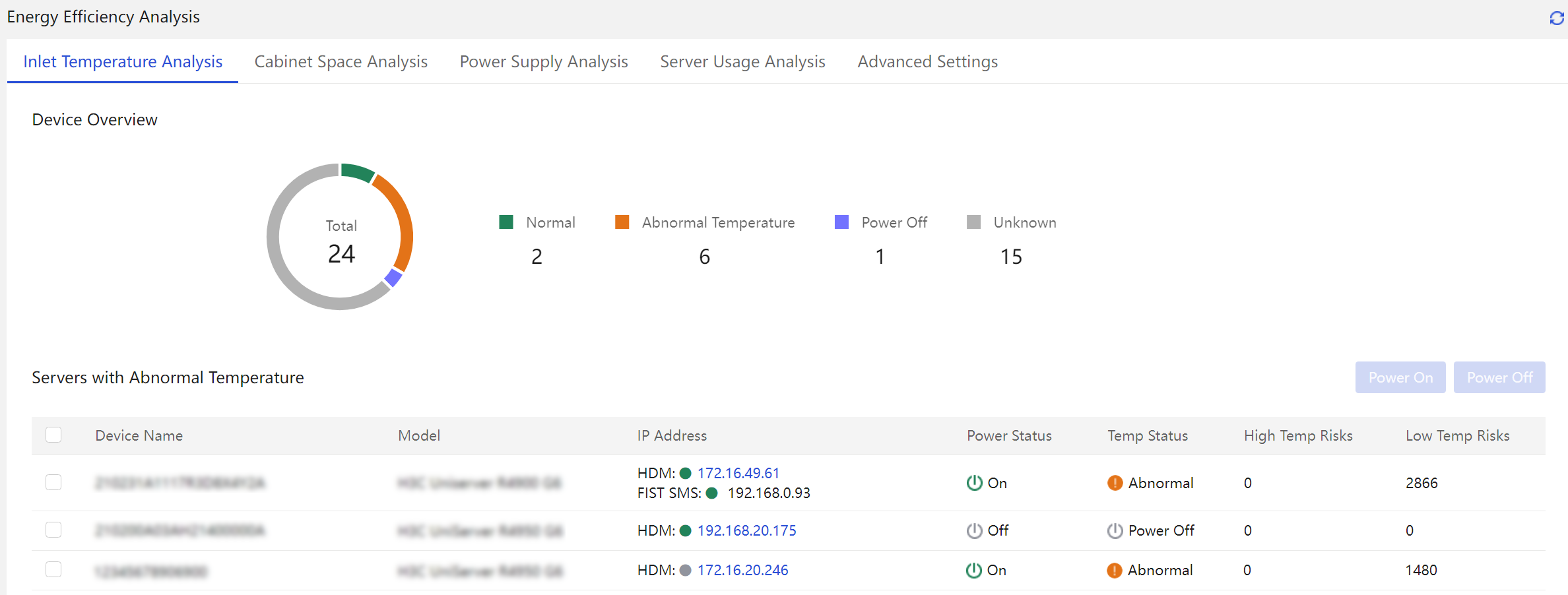
· ASHRAE Type A1: 15°C to 32°C (59°F to 89.6°F)
· ASHRAE A2 type: 10°C to 35°C (50°F to 95°F)
· ASHRAE A3 type: 5°C to 40°C (41°F to 104°F)
· ASHRAE Type A4: 5°C to 45°C (41°F to 113°F)
· Customize temperature range.
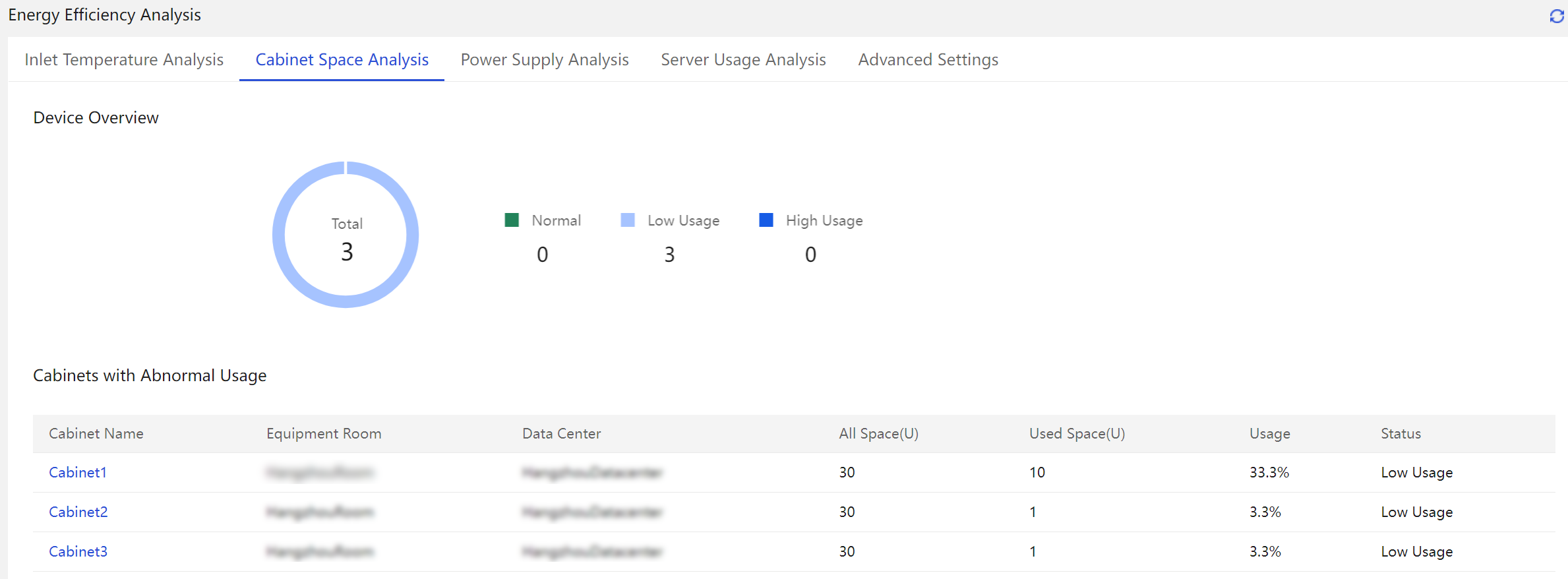
Cabinet space analysis
Cabinet space analysis involves analyzing the cabinet space in a data center, displaying pie charts of cabinet usage distribution, cabinets with abnormal space usage, total cabinet space, used cabinet space, and cabinet usage.
Figure 15 Cabinet space analysis
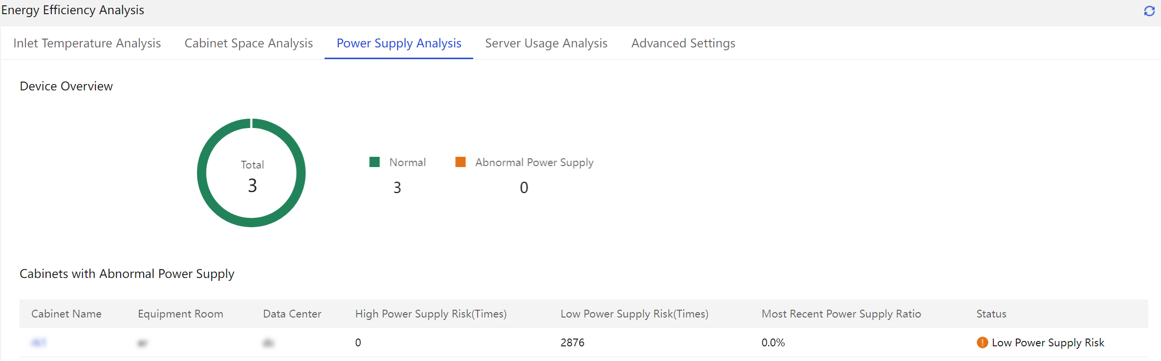
Power supply analysis
Power supply analysis involves analyzing the power supply to the cabinets within the data center, displaying pie charts of cabinet power status distribution, cabinets with abnormal power supply ratios, cabinets with high power supply occurrences, cabinets with low power supply occurrences, and the most recent power supply ratio.
Figure 16 Power supply analysis
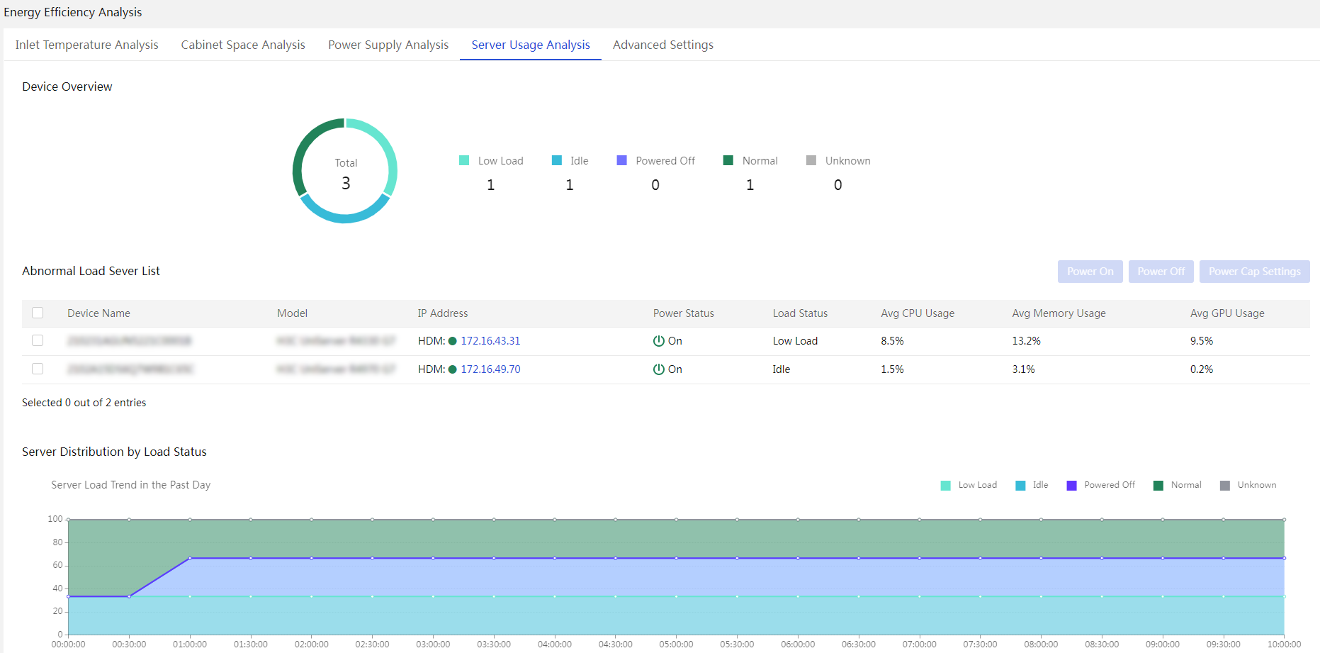
Server usage analysis
Server usage analysis assesses the usage of server CPU, GPU, and memory to identify low-load and idle devices, showing pie charts of server load distribution, lists of servers with abnormal usage, average CPU usage, average memory usage, average GPU usage, and charts of server load ratios.
Figure 17 Server usage analysis
Carbon emission management
UniSystem supports full life cycle management for data center carbon emissions. Users can effectively monitor and optimize carbon emissions through intelligent monitoring, precise calculation, and visualized analysis.
Carbon assets
Users can flexibly add the carbon asset information based on actual business conditions. To achieve efficient management of carbon assets, users can view the overall distribution and usage status of carbon assets through a visualized panoramic view.
Figure 18 Carbon assets

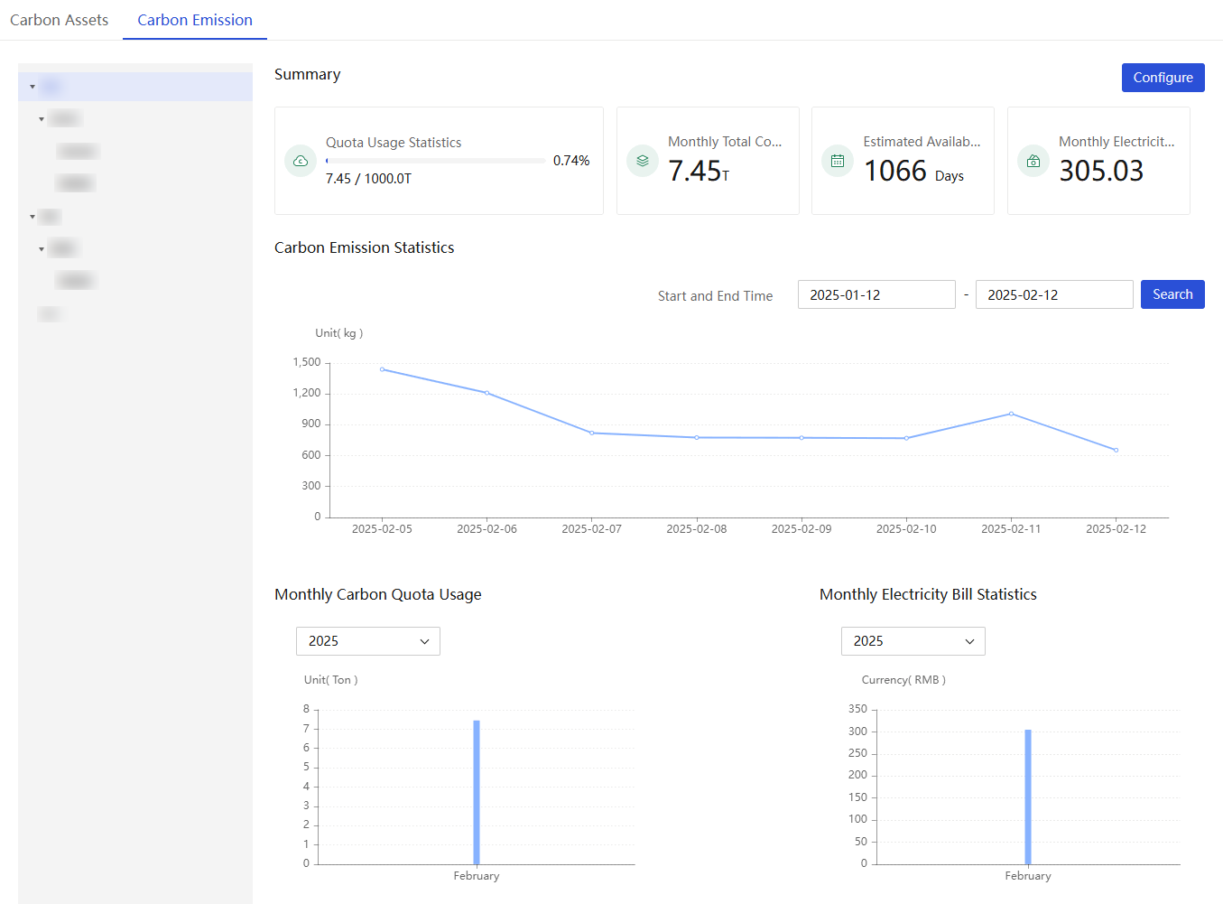
Carbon emission
UniSystem achieves digital management of data center carbon emissions through the configuration of carbon emission quotas, emission factors, power usage effectiveness, and electricity pricing. The system supports real-time monitoring and intelligent analysis of carbon emissions from three dimensions, including cabinets, rooms, and data centers. UniSystem provides real-time carbon emission monitoring, intelligent quota utilization analytics, dynamic quota availability prediction, and automated electricity cost accounting. These features enable enterprises to precisely manage their carbon footprint and optimize operations sustainably.
Figure 19 Carbon emission
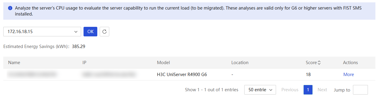
Load migration
UniSystem provides intelligent load migration evaluation and management capabilities. The system analyzes server resource usage to identify low-load servers or servers requiring load migration, and then selects target servers to optimize resource utilization and balance loads efficiently.
Figure 20 Load migration
Smart diagnosis
Automatic reporting of faults
iService Intelligent Care Service is a proactive smart service tailored for the x86 series IT products, designed to help customers with professional log analysis, hardware and software potential issue diagnosis, security vulnerability scanning, and firmware risk assessment, offering users a novel intelligent experience along with detailed analysis reports.
Repair configuration
UniSystem supports integration with the iService Smart Care cloud platform, automatically uploading SDS logs to the cloud and creating tickets when server alarms occur.
Table 11 Repair configuration
|
Configuration item |
Description |
|
Function switch |
Control the enabling status of the remote maintenance function. |
|
Connection settings |
Offer docking configuration for iService, including: iService IP/domain name, iService username, and iService password. |
|
Node configuration |
Support site configuration, including site name and site detailed address. |
|
Repair method |
Support manual and automatic fault reporting methods. |
|
Warranty card |
Support for service card configuration, including customer name, contact person's name, contact person's phone number, and contract number. |
Repair status
UniSystem supports viewing the details of manual and automatic repair tasks, including:
· Task: Name, type, operator, start time, end time, status.
· Server: Device name, IP address, repair health status, repair status, start time, end time, and remarks.
|
|
NOTE: · The iService Smart Care service requires account registration, which is currently only available in certain regions. For more information, contact Technical Support. · Customers who require the automatic ticket creation feature will also need to purchase the enhanced service of iService Smart Care. |
Server diagnostics
After prolonged operation, certain server hardware might fail due to physical wear, causing issues such as system crashes. UniSystem server diagnostics can send rapid diagnostic and stress test commands to iFIST. After startup, iFIST automatically performs diagnostics and generates reports. It also provides suggestions for resolving certain faults, helping users quickly identify and fix issues.
· Rapid diagnostics: Conduct brief and efficient diagnostic tests on the server’s operational and health status.
· Stress test: Conduct prolonged stress tests on server.
Table 12 Contents of rapid diagnostics
|
Diagnostic item |
Content |
|
System |
Perform a comprehensive health status test and a serial number validity test. |
|
BIOS |
Validate the version of BIOS firmware information. |
|
Processor |
Identify the number of CPUs and verify available memory for each CPU. Perform a brief CPU link test and a floating-point operations test and check for any MCA CPU errors. |
|
Memory |
Perform read and write tests on memory using a few algorithm models and check for any MCA memory errors. |
|
Storage |
Inspect storage modules for bandwidth, speed, health status, and capacity status of the storage controller card. Access the bandwidth and speed of NVMe SSD or PCIe SSD. Conduct self-tests on physical drives and sequential read tests on logical drives. |
|
Network adapter |
Check if the network adapter's bandwidth and speed are below the thresholds, detect MAC address mismatches, and conduct self-tests on network ports. |
|
GPU |
Check if the GPU's bandwidth and speed are below the thresholds. |
|
PCle |
Check if the PCIe device's bandwidth and speed are below the thresholds. |
|
Power supply |
Check the operational status of power supply modules. |
|
Fan |
Check the health status of fans. |
|
Temperature |
Check if the temperature sensor status of components such as memory, CPU, power supply, storage, and PCIe slots is normal. |
Table 13 Contents of stress test
|
Test item |
Content |
|
Processor |
Perform a prolonged CPU link test and a floating-point operations test and check for any MCA CPU errors. |
|
Memory |
Perform read and write tests on memory using multiple algorithm models and check for any MCA memory errors. |
|
Storage |
Conduct prolonged sequential and random read tests on physical and logical drives. |
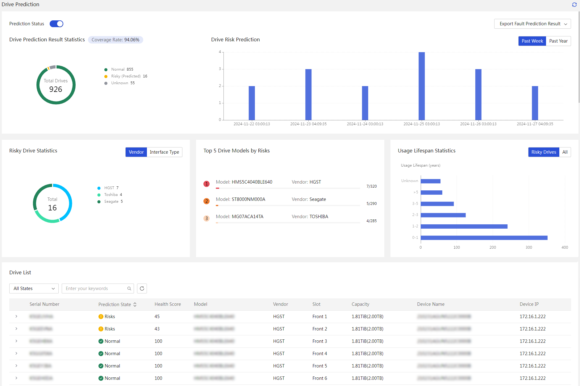
Drive failure prediction
UniSystem supports the prediction of SATA-HDD drive failures, and the overall process is shown in.
Figure 21 Full process of drive failure prediction
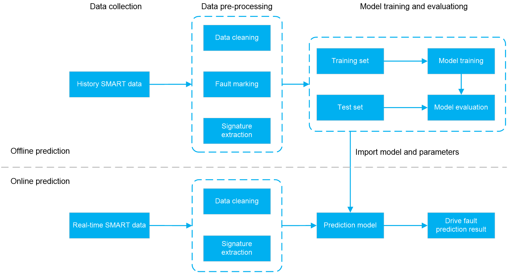
1. Drive SMART Collection
S.M.A.R.T., or Self-Monitoring Analysis and Reporting Technology, is an automated drive status detection system. It tracks the performance of components such as the read/write heads, platters, spindle motor, and electronic circuitry, utilizing embedded diagnostic commands and data is compared to predefined safety thresholds set by the vendor. If the monitored conditions approach or exceed these safety values, the system can automatically issue warnings to the user and perform minor repairs through monitoring hardware or software on the host, ensuring the safety of data in advance. Most modern drives are equipped with this technology, except for a few early models.
In drive failure prediction of UniSystem, the data flow follows the sequence: Disk -> RAID -> HDM -> UniSystem. The use of an out-of-band channel for collecting S.M.A.R.T. data ensures that user operations and in-band network bandwidth remain unaffected. The monitoring data is stored in HDM for a period of time, allowing UniSystem to access this information through the out-of-band channel even if an OS crash causes data loss.
2. Data preprocessing and model training
After acquiring the S.M.A.R.T. data from drive, targeted preprocessing is conducted to enhance the model training effectiveness. For example, data cleansing involves using scoring rules and analyzing indicator trends to remove drives that are unpredictable failures. Drive failure labeling is used for subsequent training and testing datasets. Feature extraction is performed to derive drive characteristic data using predefined engineering techniques.
UniSystem builds the optimal drive failure prediction model using the LightGBM algorithm, drawing on hundreds of thousands of open-source data points, S.M.A.R.T. data collected from live network, extensive testing and validation and also expert analysis.
3. Prediction results
For devices that are online and have an HDM interface capable of collecting drive S.M.A.R.T. data, data is collected at regular intervals. The prediction model is performed to forecast drive failures, and results are generated accordingly. Currently, UniSystem predicts HDD SATA potential failure risks 30 days in advance, achieving a detection rate of over 80% with a false positive rate below 0.18%.
Figure 22 Drive failure prediction
Memory failure prediction
On H3C G6 servers with Intel EGS processors, HDM utilizes Intel MRT-based intelligent memory repair technology to reduce unexpected downtime from memory hardware failures by over 40%. The alarm processing mechanism is as follows:
1. Memory failure collection
HDM uses the PECI channel to capture minor anomalies in real-time, such as early indicators of correctable errors (CEs), specific error locations, error types, and error frequency. The MRT model predicts the memory's risk level and isolates high-risk memory rows and cells accordingly.
2. Intelligent failure prediction
Intelligent failure prediction targets traceable and predictable failures, utilizing multi-dimensional models and various algorithms. You can use this feature to predict potential memory failures. However, predictive results might vary due to differences in system software, hardware, or configurations. The prediction results do not necessarily indicate an existing memory problem.
3. Failure self-healing repair
HDM identifies high-risk memory rows and cells and provides this information to the operating system for isolation. The OS then performs a Page Offline operation on the allocated memory to ensure the risks are isolated at the OS level. During isolation, the OS migrates data from applications on the affected memory page frames to new, secure, and available frames. These isolated page frames will not be reused for the duration of the lifecycle.
UniSystem obtains isolation repair records and memory risk alarms through HDM for statistical analysis.
Figure 23 Memory failure prediction

Intelligent retirement
Bulk erasure
When a server stops running due to the end of its lifecycle or other reasons, to prevent user data from leaking, UniSystem supports batch secure erasure of servers without the need for manual intervention.
Secure erasure depends on the HDM licensing status. To obtain licenses, see H3C Servers HDM Licensing Guide.
Table 14 Impact of secure erasure
|
Item |
Impact |
|
HDM |
· Restore HDM to factory settings. · Erase all data in the flash card. |
|
BIOS |
· Restore the default BIOS configuration. · The Administrator and User passwords on the BIOS side are erased. Users with erased passwords can enter the BIOS Setup directly without entering a password on the server's next restart. · The power-on password on the BIOS side is erased. |
|
Storage Controller |
· All logical drives under RSTe and VROC will be deleted. · All logical drives under the following LSI storage controller will be deleted. If the LSI storage controller is in RAID mode before deletion, the JBOD property of RAID mode will change to ON after deletion. ¡ RAID-LSI-9361-8i(1G)-A1-X ¡ RAID-LSI-9361-8i(2G)-1-X ¡ HBA-LSI-9560-LP-8i(4G) ¡ HBA-LSI-9560-LP-16i(8G) ¡ HBA-LSI-9500-LP-8i ¡ HBA-LSI-9500-LP-16e ¡ HBA-LSI-9500-LP-16i ¡ HBA-LSI-9540-LP-8i ¡ HBA-LSI-9311-8i · All logical drives under the following PMC storage controllers will be deleted: ¡ HBA-H460-M1 ¡ HBA-H460-B1 ¡ RAID-P460-M2 ¡ RAID-P460-B2 ¡ RAID-P460-M4 ¡ RAID-P460-B4 ¡ RAID-P4408-Mf-8i ¡ RAID-P2404-Mf-4i · The logical drives under the following MARVELL storage controllers will be deleted: ¡ RAID-MARVELL-SANTACRUZ-2i |
|
Drive |
Erase all data on the drives. |
|
SD card |
Erase all data in the SD cards. |
|
|
NOTE: · Use the secure erase feature with caution. Make sure the data to be erased is unnecessary and can be safely deleted before using this function. Otherwise, back up your data in advance to prevent the loss of important information. · Before beginning the data erasure, make sure all external storage devices connected to the server, including but not limited to portable drives, have been removed to avoid accidental data deletion. · During the data erasing process, the server will automatically reboot into iFIST to perform the erasure. After completion, the server will reboot again into the system boot item that was set before the erasure. · Before beginning data erasure, make sure the target server's iFIST software version is not lower than iFIST-1.58 and the HDM software version is not lower than HDM2-1.57 to guarantee successful data deletion. · After the HDM data is erased, the HDM management IP address will revert to the default, which may prevent users from performing further operations on the server through UniSystem. |
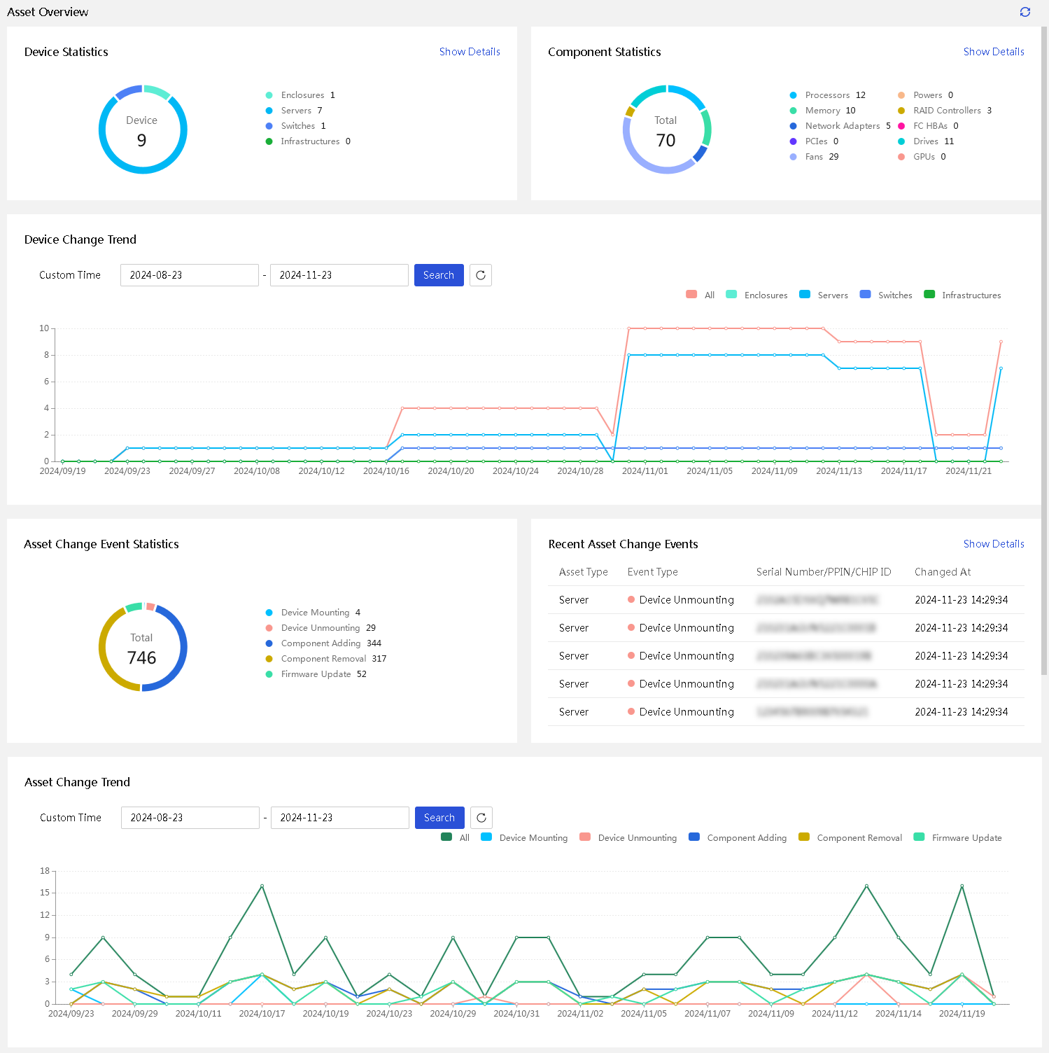
Intelligent asset management
Asset overview
UniSystem supports asset statistics and trend analysis for devices and components, such as device deployment, device removal, component addition, component removal, and firmware update.
Figure 24 Asset summary
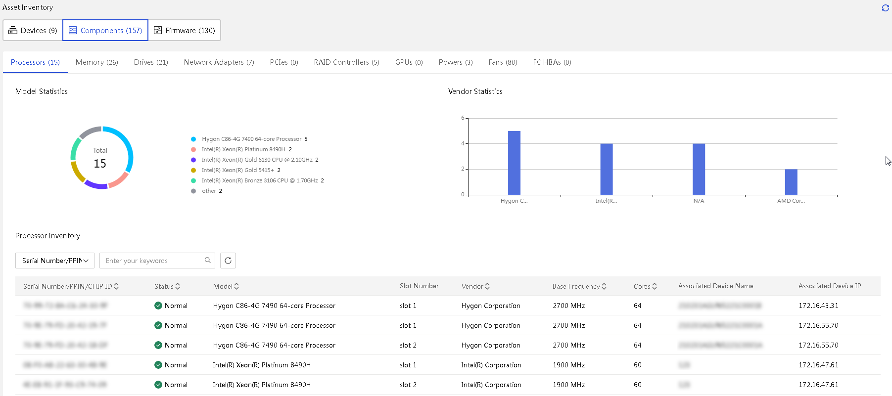
Asset inventory
UniSystem supports displaying detailed statistics for devices and components, including:
· Support categorizing and displaying device model and health status statistics for servers, enclosures, switches, and infrastructure.
· Support displaying device serial numbers, names, IP addresses, and models.
· Support displaying server asset change details, including device deployment, device removal, component addition, component removal, and firmware update.
· Support displaying statistics on server components such as processors, memory, drives, and network adapter, along with their models and vendors.
· Support displaying detailed information for components including serial numbers, models, slot number, and associated devices.
Figure 25 Device inventory
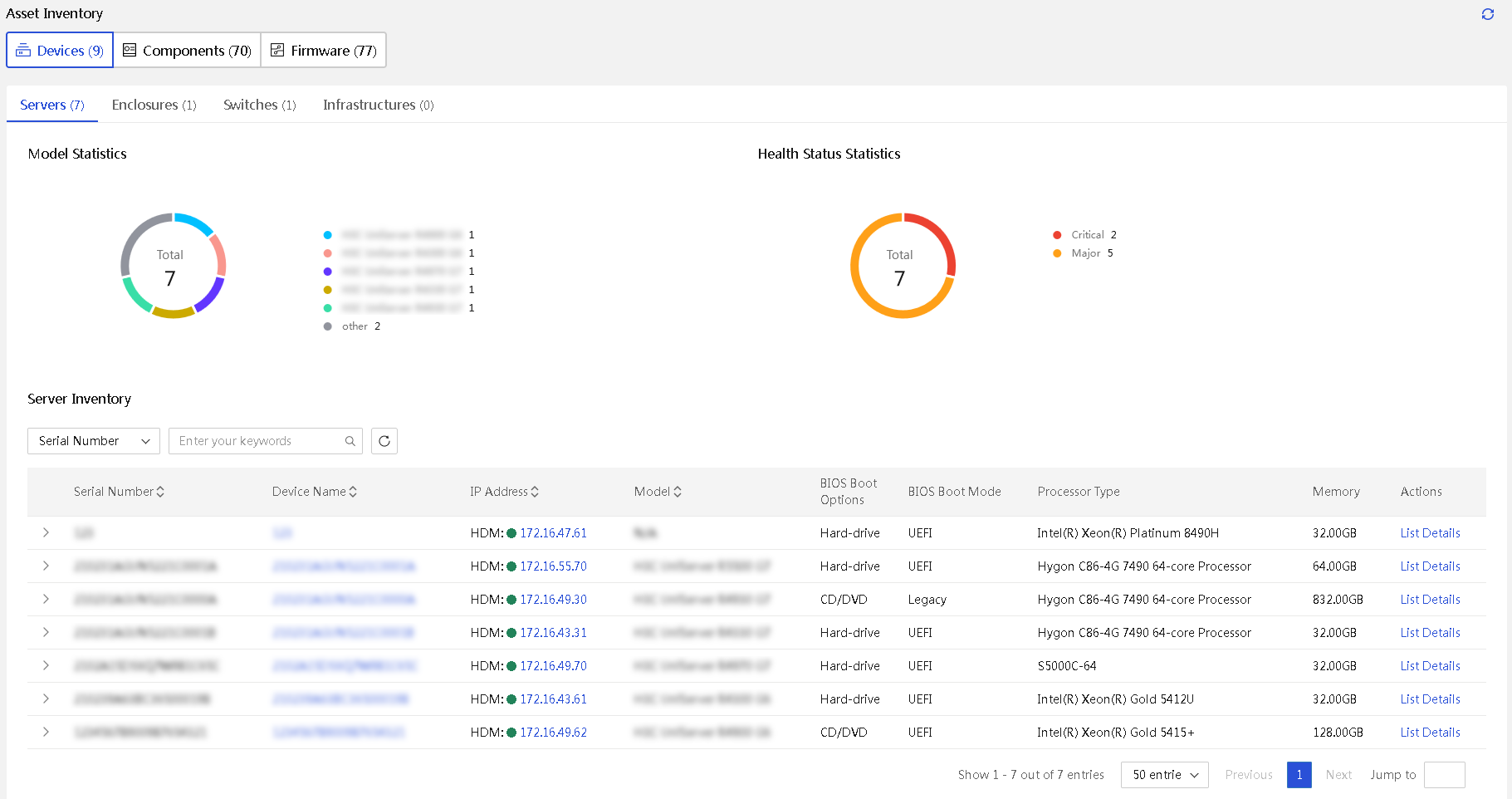
Figure 26 Component list
Asset changes
UniSystem supports recording detailed change events for devices and components, including device deployment, device removal, component addition, component removal, and firmware update. This allows for analyzing device change trends and identifying potential risks in devices and components through asset change records.
Figure 27 Asset change
Asset inspection
UniSystem enables users to inspect devices and components, automatically emailing reports. It supports immediate, scheduled, and periodic inspections and offers reports in PDF and XLSX formats. PDF reports include recommendations for devices with abnormal health status and allow for inspector information configuration.
The server report supports customized inspection checklists, including:
· Component details: Allows filtering of components such as processors, memory, network adapters, PCIe, RAID controllers, FC HBA cards, power supplies, fans, drives, GPUs, BIOS and SNMP trap configuration.
The server inspection report includes:
· Statistics: Health status, number of processor cores, memory size, product name, HDM version, BIOS version, UID LED status, power capping status, and power status.
· Details: Information on overview, CPU, memory, PCIe, network adapters, storage controllers, power supplies, fans, logical drives, drives, NVMe, and SNMP trap configuration.
The enclosure inspection report includes:
· Statistics: Health status and device model.
· Details: Information on the enclosure, blade servers, AE modules, interconnect modules, OM modules, fan modules, and power supplies.
The switch inspection report includes:
· Statistics: Health status and device model.
· Details: Information on the device, overview, modules, ports, and interfaces.
The infrastructure inspection report includes:
· Statistics: Health status, vendor, and device model.
· Details: Information on the device, sensor, modules, and latest alarm statistics.
Asset maintenance management
UniSystem supports automatic retrieval of maintenance information for managed devices from iService, enabling visual management of maintenance.
The page displays devices under maintenance and their types, supporting manual iService synchronization, as well as import and export of maintenance information.
Maintenance status includes Expired, Expiring Soon, Normal and Unknown.
Figure 28 Asset maintenance management

System management
Network configuration
UniSystem supports configuring user access IP, subnet mask, and gateway. At the same time, to facilitate UniSystem's access to external networks, it also supports interfacing with DNS and proxy servers.
Table 15 Deployment mode
|
Deployment mode |
Description |
|
No installation required |
Use the network configuration of the running environment. The Web page does not offer network setting functions. |
|
Import VMs |
· The VM console supports setting IPv4 and IPv6 network parameters. · The web page supports setting the host name, IPv4 & IPv6 network parameters, DNS server settings, and other functions. |
|
AE node |
· The display screen or KVM of the node supports setting IPv4 & IPv6 network parameters. · The web page supports setting the host name, IPv4 & IPv6 network parameters, and DNS server configurations. |
|
U-Center integration |
The network configuration using the U-Center operating environment does not support the configuration of network parameters independently. |
Supported configuration parameters include:
· Support viewing/setting the UniSystem system host name.
· Support viewing network port names, MAC addresses, network adapter speeds, network adapter status, network modes (DHCP or static), and IP addresses. Support configuring network modes, and adding/deleting IP addresses. Support both IPv4 and IPv6.
· Support the display of IPv4 and IPv6 routing tables.
· Support connectivity testing for the destination address, which supports IPv4, IPv6, and domain name addresses.
· Support the configuration of DNS servers, including setting up preferred and alternative IPv4 and IPv6 DNS servers.
Time settings
In a data center equipment management environment, ensuring time consistency across all devices is very important. Consider the following scenarios:
· When the server generates an SNMP TRAP alarm, if the timestamps of the server and UniSystem do not match, it is unclear which system's timestamp should be considered authoritative for the TRAP alarm.
· After the server malfunctioned, the timestamp in the downloaded log system was incorrect, making it impossible to ascertain the operations before and after the incident.
· In the AE version, UniSystem supports dual-machine master-standby cluster systems. If the timestamps of the master and standby do not synchronize, the entire system will be in disarray, reducing its availability and performance.
To ensure the time consistency of the management device's alarm system, log system, and cluster system, UniSystem supports user configuration of their own environment's NTP server and batch setting of the server's NTP server, while also supporting manual system time setting.
Table 16 Time setting feature
|
Setup method. |
Supported parameters |
|
NTP setup |
· Display the current system time · Set whether to sync automatically · Primary NTP server configuration · Secondary NTP server configuration |
|
Manual setup |
· Display the current system time · Set the current time |
Proxy server settings
To ensure the security of their internal network, enterprises commonly isolate it from external networks. Proxy servers can achieve network isolation. By setting up a proxy server as an intermediary node in the network, internal and external networks can be effectively isolated to protect the security of the internal network, which is why it is widely used by enterprises. UniSystem features such as remote REPO download and automatic repair require interaction with external networks. If a company's network architecture employs a proxy server for Internet isolation, users must configure the relevant proxy server parameters in UniSystem.
Figure 29 Proxy agent
Supported parameters include:
· Whether to enable the proxy server.
· Proxy server username and password.
· Data sent to the exception address will not go through the proxy.
· HTTP proxy server address and port.
· HTTPS proxy server address and port.
Backup server configuration
UniSystem supports regular or cycle-based automatic system data backups to remote servers, and it supports data transfer through protocols such as SFTP, SCP, CIFS, and NFS. The current system supports adding up to 10 backup servers.
Supported backup data includes:
· Asset inspection reports
· Alarm center:
¡ Current alarms
¡ History alarms alarms
¡ Events
¡ Suppressed alarms and events
· UniSystem data
Essential security management
The UniSystem security management encompasses two dimensions: data security and usage security. Data security includes secure transmission channels and encryption of sensitive information. Software usage safety comprises user management, allowlist management, UniSystem software backup and recovery, cluster management, and configuration of login security features.
Data security
UniSystem supports access through both HTTP and HTTPS channels. For scenarios requiring higher security for data transmission, use the HTTPS data access channel as a best practice. UniSystem encrypts sensitive information regardless of the access channel used.
· When users log in, UniSystem encrypts the entered password with RSA 2048 before sending it to the backend for verification, preventing password leaks due to intercepted data transmissions.
· Users' passwords must be stored in the UniSystem database. To prevent leaks from database breaches, UniSystem encrypts the plaintext passwords using the MD5+Salt algorithm.
· UniSystem supports alarm forwarding for servers, ensuring the security of information transmission through various encryption methods.
Table 17 Alarm forwarding encryption method
|
Alarm forwarding method |
Encryption method |
|
SNMP forwarding |
· Use MD5 and SHA authentication protocols · Use DES and AES128 privacy protocols |
|
SMTP forwarding |
Use STARTTLS and SSL/TLS encryption protocols. |
|
WeCom forwarding |
Transmit via HTTPS |
|
SMS forwarding |
Use AES encryption for transmission |
|
Voice forwarding |
Use AES encryption for transmission |
User management
Local users
By default, UniSystem has a user named admin as the administrator. You can add 100 common users. The permissions of users are determined by their roles. Different roles are assigned module permissions that match their features, enabling them to operate corresponding UniSystem modules.
The system predefines several roles, among which the Administrator has full operational and query permissions for all modules, while the ReadOnly role is limited to query permissions across modules. This role-based access control mechanism achieves detailed permission management. Users can only access functions within the authorized scope. This mechanism effectively balances system security with operational convenience. Different roles and permission modules involve typical features as shown in Table 18.
Table 18 Roles and permission modules
|
Roles |
Permission module |
Description |
|
N/A |
User configuration |
User management, LDAP user management, online users, SSL certificate management, and menus (adding shortcuts) |
|
System administrator |
System management |
Network settings, proxy settings, time settings, maintenance and update, and login security information configuration, remote support, cluster management, custom menus, system connection, and backup server configuration |
|
Device administrator |
Device management |
Chassis list chassis topology, server list, switch list, infrastructure list, custom monitoring templates, data center management, equipment room list, rack list, information reporting, asset management, drive failure prediction, and memory failure prediction |
|
Power administrator |
Power management |
Power management on all managed devices |
|
Deployment administrator |
Deployment management |
Enclosure template, enclosure template application, server template, server template application, firmware template, switch template, enclosure configuration file, enclosure slot configuration file, server configuration file, address pool, network template, clone image, driveless startup, DHCP server, software push installation, PXE, image management (except REPO synchronization), software license management, and server diagnostics |
|
Component administrator |
Component update |
REPO baseline, component update, firmware update, and image management |
|
Energy administrator |
Energy efficiency management |
Energy efficiency statistics, one-key emergency power consumption, rack smart power management, energy efficiency analysis, carbon emission management, and load migration |
|
Data erasure administrator |
Data erasure |
Secure erasure |
|
Scope administrator |
Scope |
Scope |
|
ReadOnly |
Information query |
All information query menus and features, operation log, custom menus (creation and switch features), and password modification |
Figure 30 User role management
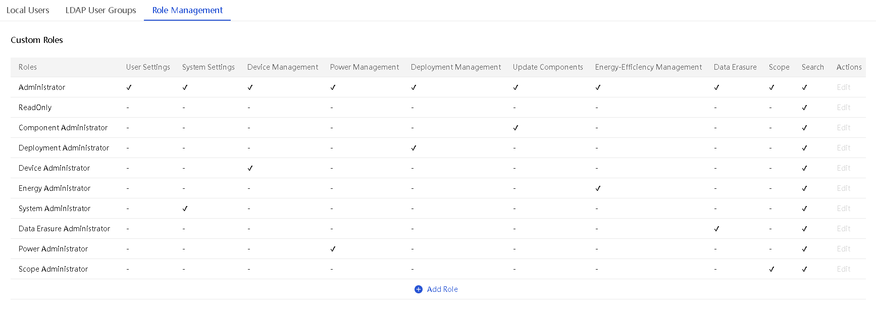
To achieve fine-grained management and security isolation of roles, UniSystem facilitates role-based scope management by associating specific scopes with user roles. The system effectively divides resources into different scopes, ensuring users only access and manage resources within their authorized boundaries.
· Supports viewing, adding, deleting, and modifying scopes.
· Resources include: servers, enclosures, switches, infrastructure, data centers, server configuration templates, enclosures configuration templates, and switch configuration templates.
LDAP user groups
Lightweight Directory Access Protocol (LDAP) enables you to efficiently access and maintain distributed directory information services over an IP network. By utilizing the existing authentication and authorization modes in LDAP for direct access to UniSystem, repetitive user configuration tasks are avoided.
UniSystem supports integration with up to five LDAP servers, with each server supporting a maximum of 100 user groups.
Account security
Account security includes password complexity check, maximum password validity, disabling history passwords, account lockout threshold, and account lockout duration as follows:
· Complexity check: If this feature is enabled, passwords must meet the following complexity requirements:
¡ 8 to 20 characters in length. Case sensitive. Valid characters are letters, digits, spaces, and the following special characters `~!@#$%^&*()_+-=[]\{}|;’:”,./<>?
¡ Must contain characters from at least two of the following categories: uppercase letters, lowercase letters, and digits.
¡ Must contain at least one space or special character.
¡ Cannot be identical to the username or the reverse of the username.
¡ Must meet the requirement set by the password history count parameter.
· Maximum password validity: Maximum number of days that a password can be used. When a password is about to expire, HDM prompts the user to change the password.
· Password history count: Number of unique passwords that a user must create before an old password can be reused.
· Account lockout threshold: Number of consecutive login failures that will cause a user account to be locked.
· Account lockout duration: Amount of time before a locked account can be used again.
SSL certificate management
UniSystem supports the HTTPS secure access mode and HTTPS SSL certificate management. SSL certificates are used in HTTPS connections to verify the identity of the Web server. Certificate management involves various operations such as viewing current certificate information (basic information, issuer, and validity), generating CSR files, and importing signed certificates generated from the CSR.
Figure 31 SSL certificate management
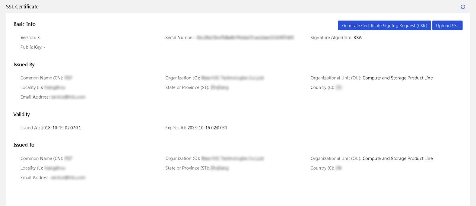
Allowlist management
UniSystem supports setting up a login allowlist and can configure up to 10 login rules. Users can log in as long as they match one rule. The supported configuration rules include permissible login time periods and allowed IP address ranges.
Maintenance and update
Backup and maintenance
UniSystem supports backup and restoration of software, allowing users to manually back up configurations from UniSystem to a local site for a restoration point periodically. When users need to migrate UniSystem software, they can restore it to a restore point by importing backup files.
· Supported data for backup and recovery: Device information, task information within component updates, configuration template/file information, address pool information, and user information.
· Data not supported for backup and recovery: REPO baseline, images uploaded on the image management page, cloned images, diskless boot storage volumes, monitoring settings, and UniSystem auto-upgrade version update files.
Restoring the backup data will overwrite the current UniSystem data.
Version update
UniSystem supports self-version management, allowing users to check the current UniSystem version information and update time, as well as upload upgrade packs and update the UniSystem version through the interface.
Figure 32 Version update
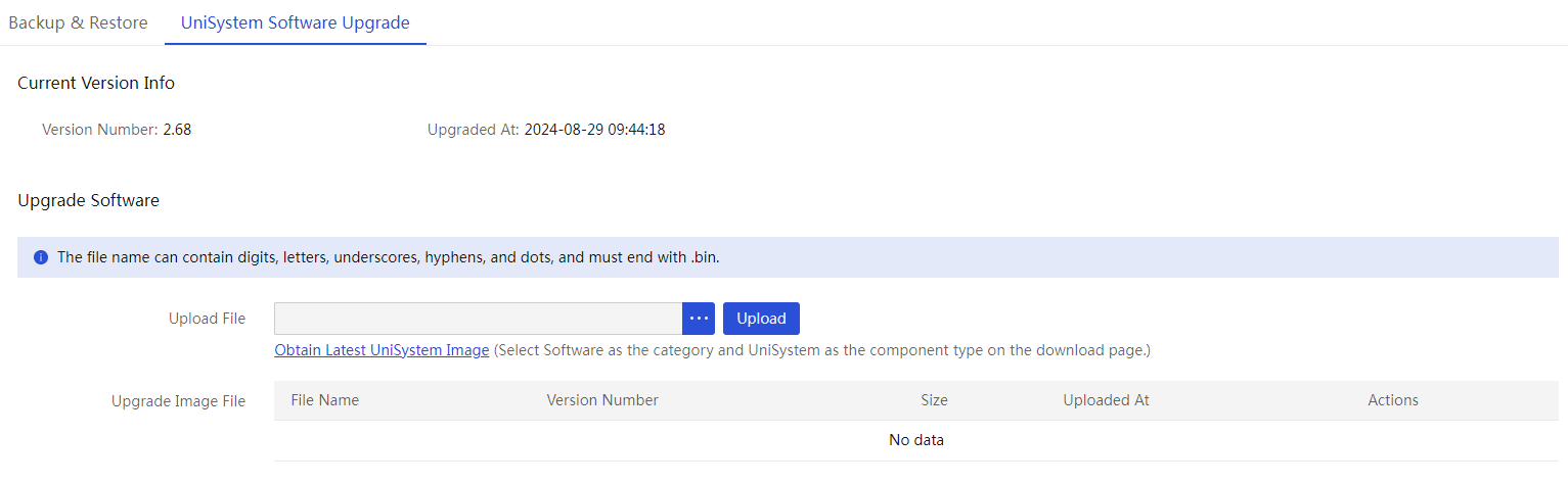
The service will be interrupted during the update, and after the update is completed, UniSystem will automatically restart and return to the login page. The overall update time is about 15 minutes.
Cluster management
UniSystem supports the creation of a 1+1 master-standby cluster, currently only for AE usage scenarios. After the cluster is successfully created, UniSystem can automatically monitor the master node's operational status, and in case of failure, it can seamlessly switch to the standby node to reduce service issues caused by AE failures.
Login security information configuration
UniSystem supports multi-user management, allowing multiple users to operate the same device. Users can use this feature to customize a prompt message on the UniSystem login page, reducing the risk of incorrect operations.
Tools
DHCP server
UniSystem supports automatic assignment of HDM IP addresses or system IP addresses to clients within the same local area network. Users can configure the DHCP server to allocate IP addresses to clients dynamically or statically.
· Dynamic method: When a client requests an IP address from a DHCP server, the server randomly assigns an IP address to the client from a pool of addresses.
· Static method: The DHCP server binds IP addresses to MAC addresses, and when a client requests an IP address, the DHCP server checks if the client's MAC address is allowed allocation. If allowed, it assigns the bound IP address to the client.
· It supports downloading the DHCP assigned address list for user convenience in verification and inspection.
PXE server
Pre-boot Execution Environment (PXE) provides a mechanism to boot servers using a network interface. UniSystem integrates the PXE server-side service, allowing users to batch install operating systems for servers using this feature. UniSystem's PXE server supports multiple BootLoader configurations, including PXELINUX, GRUB2, and iPXE. At the same time, it supports customizing installation parameters when installing Red Hat Linux Enterprise and CentOS images.
Restrictions: PXE server is supported only when UniSystem runs on the AE module.
Software push installation
To meet user needs for quick, bulk installation or deployment of system environments, UniSystem supports the function of pushing software or installation scripts to the server's operating system in batches without the need for an agent. UniSystem transfers software to the operating system and executes corresponding system commands using WinRM technology on Windows and SSH technology on Linux/VMware ESXi. At the same time, the software push installation can support batch installation of FIST SMS.
Users can customize the software installation and scripts to be executed according to the script template format, enabling batch retrieval and execution of server system information on the UniSystem page, such as device information and system logs.
Remote Commands
During routine operations and maintenance, when personnel identify offline devices or encounter network-related alerts, they typically assess the network connectivity of the affected devices. UniSystem offers three commands—Ping, IPMI, and Redfish—that facilitate batch operations via the system interface, enabling efficient device connectivity testing and basic information querying to enhance operational efficiency and user experience.
· Ping: Supports network connectivity testing for IPv4/IPv6 addresses.
· IPMI: Supports executing IPMI commands in batches on multiple devices.
· Redfish: Supports executing Redfish commands in batches on multiple devices.
Network connection method
The network diagram of UniSystem includes UniSystem client, UniSystem server, and managed devices.
· UniSystem client: PCs or servers accessing UniSystem through a browser.
· UniSystem server: PCs, servers, or AE modules installed with UniSystem (the AE modules come with UniSystem software pre-installed).
· Managed device: Devices managed by UniSystem, including chassis, switches, servers, and infrastructure.
Figure 33 UniSystem network diagram
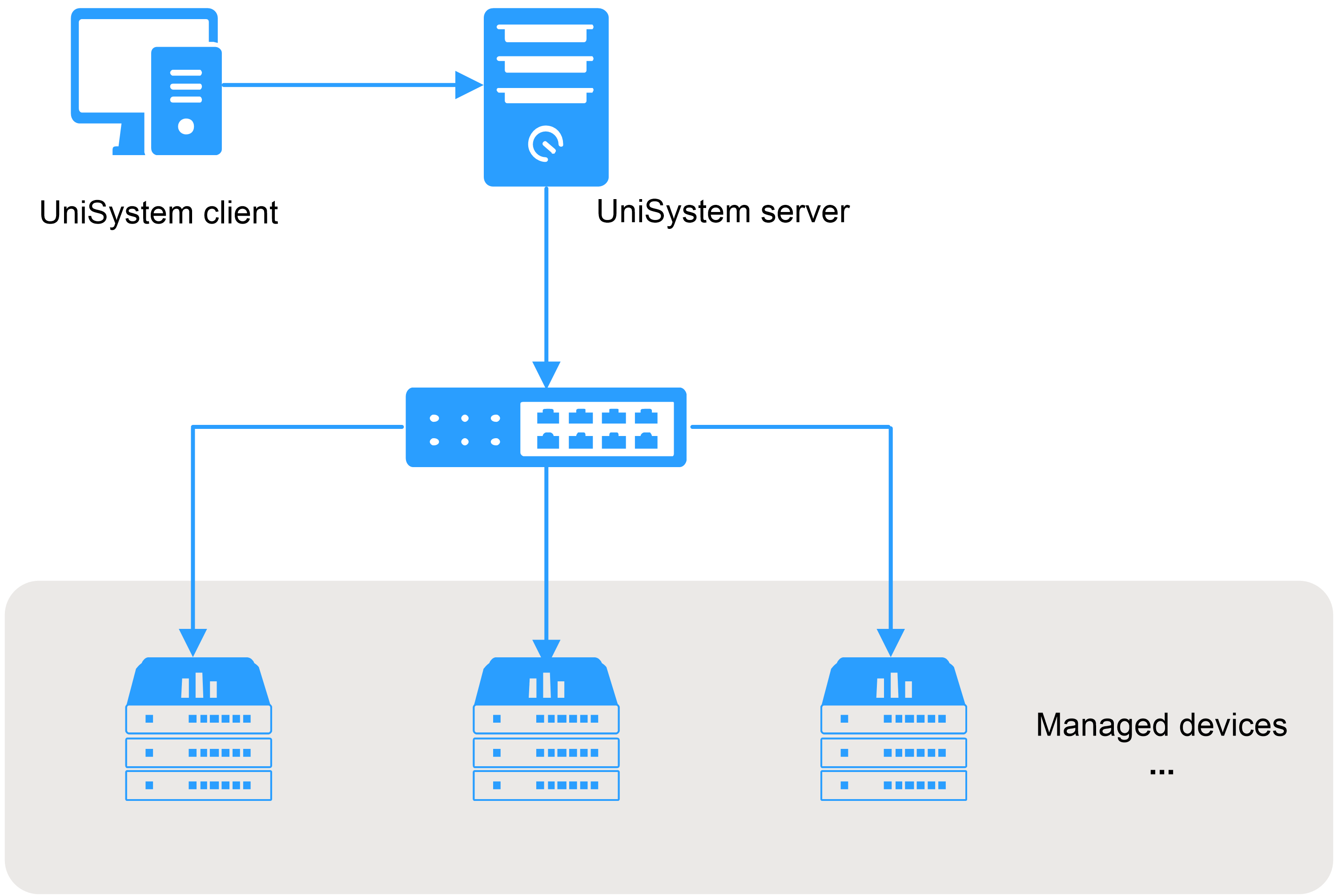
Configuration requirements
UniSystem can be installed on either a virtual or physical machine. The server configuration requirements are shown in Table 19.
Table 19 UniSystem server configuration instructions
|
Deployment method |
CPU architecture |
CPU |
Memory |
Drive |
Network adapter |
|
No installation required |
X86 |
Quad-core and above |
8GB and above |
100GB and above |
One or more |
|
VM OVA |
N/A |
8 cores or more |
32GB or above |
500GB and above |
One or more |
The software configuration requirements for the UniSystem server are shown in Table 20.
Table 20 Software configuration requirements
|
Software configuration requirements |
Remarks |
||
|
Operating System |
Kylin |
Kylin ServerV10 SP3 |
· Only supports 64-bit operating systems. · Only supports the portable version. |
|
Linux |
Rocky Linux 9.2 |
||
|
Red Hat Enterprise Linux 7.3 |
|||
|
Red Hat Enterprise Linux 7.9 |
|||
|
Red Hat Enterprise Linux 8.6 |
|||
|
CentOS 7.4 |
Only supports 64-bit operating systems. |
||
|
CentOS 7.5 |
|||
|
Windows |
Microsoft Windows 7 |
||
|
Microsoft Windows 10 |
|||
|
Microsoft Windows 11 |
|||
|
Microsoft Windows 2012 R2 |
|||
|
Microsoft Windows 2016 |
|||
|
Microsoft Windows 2019 |
|||
|
Kylin |
Kylin ServerV10 SP3 |
||
|
VMware ESXi |
VMware ESXi 6.5/6.7 |
Only supports .ova installation. |
|
|
Software |
OpenJDK 1.8 (64 bit) |
- |
|
The browser types and versions supported by UniSystem are shown in Table 21.
Table 21 Client configuration requirements
|
Browser version |
Resolution |
|
|
· Google Chrome 66.0 and above · Mozilla Firefox 60.0 or above |
1600*900 or higher |
|
Glossary and acronyms
|
Terms |
Description |
|
UniSystem |
H3C intelligent management center software |
|
AE |
APP Engine, a special node on the chassis. UniSystem runs on the node. |
|
BMC |
Baseboard Management Controller, an out-of-band management system for servers. |
|
BIOS |
Basic Input Output System |
|
CPLD |
Complex Programmable Logic Device |
|
CPU |
Central Processing Unit |
|
DHCP |
Dynamic Host Configuration Protocol, used to dynamically assign IP addresses and other network configuration parameters to network devices. |
|
FIST SMS |
FIST System Management Service, server in-band management software used with UniSystem. |
|
GUI |
Graphical User Interface |
|
HDM |
Hardware Device Management, also known as BMC (software developed by H3C) |
|
iFIST |
Integrated Fast Intelligent Scalable Toolkit |
|
IPMI |
Intelligent Platform Management Interface, a standard hardware management interface to facilitate out-of-band management through HDM |
|
OM |
Onboard Manager, the management module of the chassis |
|
OS |
Operating system |
|
PXE |
Preboot Execution Environment |
|
RAID |
Redundant Arrays of Independent Disks |
|
winRM |
Windows Remote Management |
|
DNS |
Domain name resolution |
|
NTP |
Network Time Protocol |
|
LDAP |
Lightweight Directory Access Protocol |
|
SN |
Serial number, the serial number of the server |
|
REPO |
Repository, a collection of server firmware and drivers |
|
SDS |
Smart Diagnose System, an intelligent diagnostic system for the entire lifecycle of server equipment |
|
SSDP |
Simple Service Discovery Protocol |
|
HBA |
Host Bus Adapter |
|
PPIN |
Protected Processor Identification Number |
|
SNMP |
Simple Network Management Protocol |
|
SMTP |
Simple Mail Transfer Protocol |
