- Released At: 18-04-2024
- Page Views:
- Downloads:
- Table of Contents
- Related Documents
-
EPON Technology White Paper
Copyright © 2024 New H3C Technologies Co., Ltd. All rights reserved.
No part of this manual may be reproduced or transmitted in any form or by any means without prior written consent of New H3C Technologies Co., Ltd.
Except for the trademarks of New H3C Technologies Co., Ltd., any trademarks that may be mentioned in this document are the property of their respective owners.
The content in this text comprises generic technical information, some of which might not be applicable to the product you purchased.
Contents
EPON interface types and numbering
Managing ONU devices through OLT
ONU registration and onboarding
Residential area video surveillance
PON overview
Background
With the emergence of high-bandwidth services such as online gaming and IPTV, traditional access methods such as ADSL are no longer able to meet user bandwidth requirements. PON (Passive Optical Network), as an access network technology, can implement fiber optic to the home, satisfying the high-bandwidth requirement of the "last kilometer" in the access layer network.
The PON technology includes:
· Ethernet PON (EPON), a passive optical network based on Ethernet, is based on the IEEE 802.3ah/802.3av standards.
· Gigabit PON (GPON): Mainly based on the ITU-T G.984 series standard.
This document mainly describes EPON technology.
Technical benefits of PON
The PON technology has the following benefits:
· High bandwidth
The 10G PON OLT can provide a maximum bandwidth of 10Gbps downstream and 10Gbps upstream for the ONU.
· Long distance access
It can support a transmission distance up to 20km.
· Simultaneous access to multiple services such as broadband internet, IPTV, and VoIP (Internet telephony).
· In a passive Optical Distribution Network (ODN), there is no need for maintenance of active devices, which saves operation expenditure (OPEX).Fiber optics and passive splitters are less affected by electromagnetic interference (EMI) and lightning, resulting in fewer fault points.
· Point-to-Multipoint (P2MP) network structure supports flexibility in expansion.
PON network model
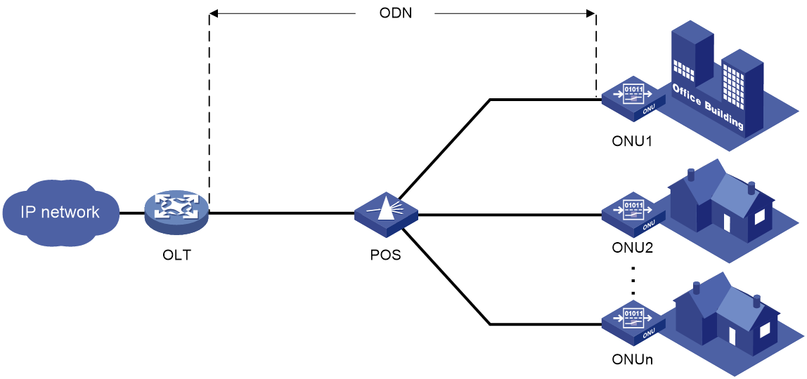
As shown in Figure 1, PON is a single-fiber bidirectional optical access network with a point-to-multipoint structure. Its typical network is composed of the following parts:
· The Optical Line Terminal (OLT) is the core device of the PON system, usually placed in the central machine room. It is used for the unified management of the ONU and converges and transfers access services to the IP network.
· A Passive Optical Splitter (POS) is used to distribute downstream data from the OLT to each ONU, and to gather upstream data from each ONU to the OLT.
The splitting ratio of POS can reach up to 1:128, which means each OLT optical module interface can connect to a maximum of 128 ONUs.
· Optical Distribution Network (ODN): Composed of fiber optics and one to several POS, among other passive optical components, it provides a light signal transmission channel between OLT and ONU.
· Optical network unit (ONU): Customer-side device in an PON system. An ONU connects to user PCs, set-top boxes, and switches, and is typically deployed at a user home, corridor, or road side. An ONU responds to the management command sent by an OLT, and forwards user data to the OLT.
EPON implementation
EPON OAMPDU format
Ethernet OAM (Operation, Administration and Maintenance) is a tool for monitoring network outages. It operates at the data link layer (DDL), using periodic exchanges of OAM protocol data units (OAMPDUs) between devices to report the state of the network, enabling network administrators to manage the management network (MGT) more effectively.
ONU and OLT achieve extended OAM discovery (including capability notification, additional information exchange, and OAM message version validation) by attaching extra expansion TLVs (Organization Specific Information TLV) in the standard OAMPDU. Through the extended OAMPDU, the connection request and response between OLT and ONU devices can be completed, enabling remote operation, maintenance, and management of ONU devices by OLT. This specifically includes ONU basic information and capability notification, user port configuration, VLAN configuration, ONU upgrade/restart operations, and configuration of multicast, QoS, VoIP functions.
The basic format of the expanded OAMPDU message is shown in Figure 2, and the value of each byte is as shown in Table 1.
Figure 2 Expanded OAM message format for expansion of OAMPDU messages
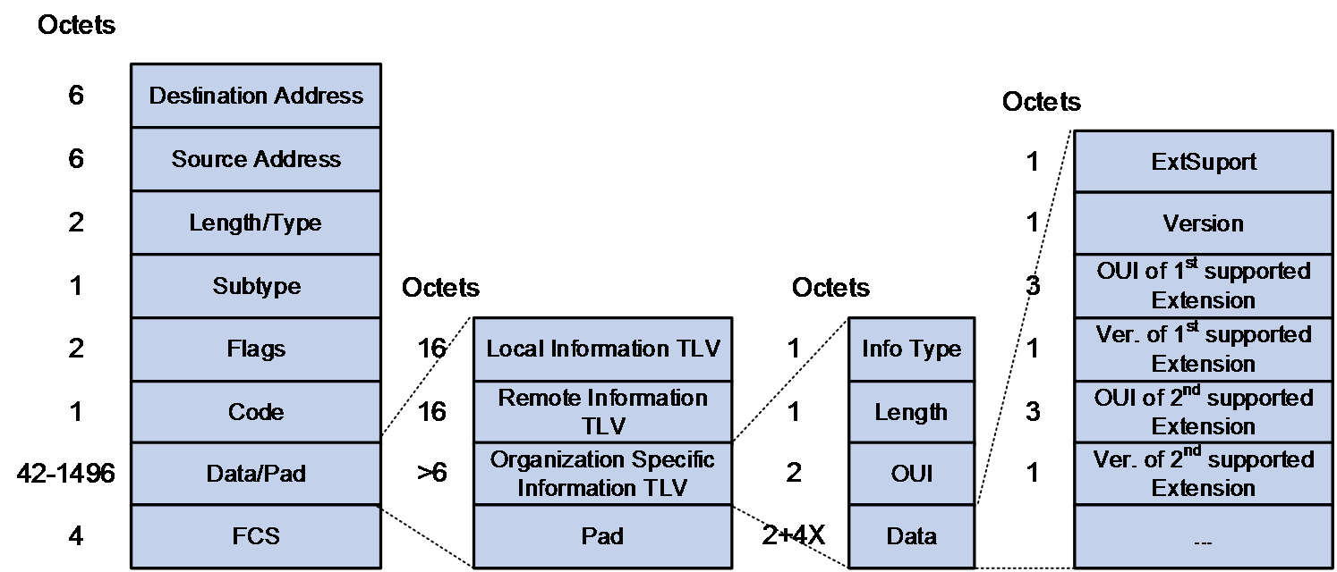
Table 1 Expanded OAMPDU message fields
|
Field |
Description |
|
Destination Address |
The Slow_Protocols_Multicast address as defined by IEEE 802.3. |
|
Source Address |
The MAC address of the port that transmits the OAMPDU. |
|
Length/Type |
The type value of Slow Protocols (Slow_Protocols_Type) in Ethernet is 0x8809. |
|
Subtype |
The subtype of the slow protocol, the OAM protocol, corresponds to the subtype value of 0x03. |
|
Flags |
State marker, see specific regulations in IEEE 802.3 Clause 57. |
|
Code |
Indicate different OAMPDU messages as specified in IEEE 802.3 Clause 57. |
|
Data/Pad |
The effective payload of the OAMPDU |
|
FCS |
Frame Check Sequence |
|
Local Information TLV Remote Information TLV |
Standard Information TLV (Local Information TLV and Remote Information TLV) During the keep-alive process in OAM connection, the transmitting end (OLT or ONU) only needs to fill in the standard Information TLV in the OAMPDU used for keeping the connection alive. |
|
Organization Specific Information TLV |
The expanded Information TLV includes the following fields: · Info Type: The value is fixed at 0xFE, indicating that the data type of this TLV is Organization Specific Information TLV. · Length: indicates the length of this TLV. · OUI: a unique identification for an institution. For example, the provisional OUI for China Telecom is set as 0x111111. · Data: The data carried by this TLV, includes: ¡ ExtSupport: Indicates whether the OAM expansion of this OUI is supported (1 means yes, 0 means no). ¡ Version: OAM version number ¡ The OUI-Version list indicates that the device supports the expansion of OAM and its version number, released by the organization corresponding to the OUI. |
|
Pad |
The remaining fields in the OAM frame are filled with "0x00" for padding. |
EPON working mechanism
Overview
The working process of the EPON system includes:
1. ONU Registration: Incorporates a new connection or non-online ONU into the OLT, where the OLT allocates a unique identity mark, LLID (Logical Link ID), for each ONU.
2. Expanded OAM Connection: After the completion of the expanded OAM connection establishment, the OLT can transmit data to the ONU and remotely configure and manage the ONU.
3. Dynamic Bandwidth Allocation: The data transmission time slots (upstream bandwidth) required for each ONU to transmit data are uniformly allocated by the OLT according to the Dynamic Bandwidth Allocation (DBA) algorithm. This can prevent upstream data conflicts.
4. Data transmission occurs between OLT and ONU.
ONU registration
The Multipoint Control Protocol (MPCP) defines the MAC control mechanism for point-to-multipoint optical networks. During the ONU registration process to the OLT, the following types of MPCP messages need to be used:
· Authorization (GATE) message
¡ Detected GATE message: Broadcasted by OLT, used for ONU discovery.
¡ Standard GATE messages: Sent by the OLT to the ONU in a unicast method for the purpose of bandwidth allocation.
· Registration request (REGISTER_REQ) message
· Register message
· Registration Validation (REGISTER_ACK) Message.
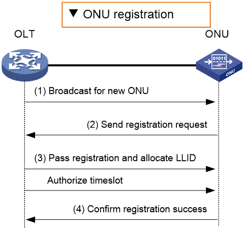
As shown in Figure 3, the ONU registration process is as follows:
1. At time T0, the OLT broadcasts a discovery GATE message to all ONUs, with the time label value in the message set to T0.
2. Upon receiving the message, the unregistered ONU adjusts its local time to the 'label value' T0 found in the GATE, waits for a random 'section' of time, and transmits a REGISTER_REQ message to the OLT at the T1 moment. The 'label value' in this 'message' is T1.
3. At time T2, OLT receives the REGISTER_REQ message from ONU, obtains the ONU's MAC address, and calculates the round-trip time (RTT) value.
|
|
NOTE: The formula RTT = (T2-T0) - (T1-T0) = T2-T1 is primarily used for time synchronization between ONU and OLT. |
The OLT unicasts a REGISTER message and a standard GATE message to the MAC address of the ONU in the REGISTER_REQ message.
¡ The REGISTER message includes the LLID allocated by the OLT for the ONU.
¡ The GATE message includes the time slot in which the OLT gives authorization to the ONU to transmit messages.
4. Upon receiving the REGISTER and ordinary GATE messages, the ONU transmits a REGISTER_ACK message to the OLT during the time slot authorized by the regular GATE message, thereby completing the registration.
Figure 3 ONU registration
Expanding OAM connection
The process of establishing an expansion OAM connection is as follows:
1. The ONU and OLT have established a standard OAM connection.
2. The ONU reports its supported OUI (Organizationally Unique Identifier) and the expanded OAM version number to the OLT.
3. The OLT validates whether the OUI and expansion OAM version number reported by this ONU are in the local list of supported OUI and expansion OAM version numbers. If it exists, then the expansion OAM connection establishment for this ONU is successful.
Dynamic bandwidth allocation
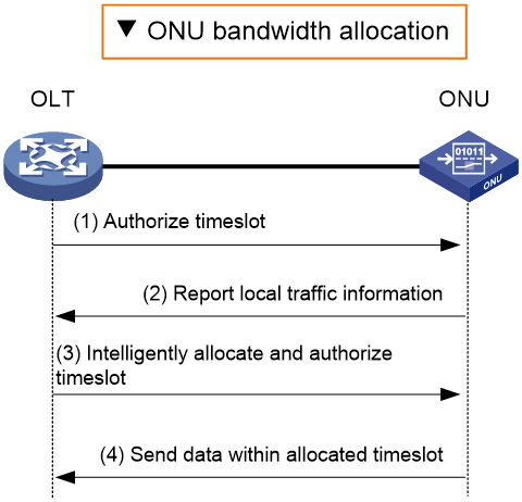
As shown in Figure 4, the process of OLT allocating upstream bandwidth to ONU is as follows:
1. The OLT transmits a regular GATE message to inform the ONU of the time slot for sending REPORT messages.
2. The ONU transmits a REPORT message within the allocated time slot to inform the OLT of its local status (such as buffer usage) to help the OLT intelligently allocate time slots.
3. Upon receiving the REPORT message from the ONU, the OLT allocates data transmission time slots (bandwidth) to the ONU based on the current bandwidth status.
4. Upon receiving the authorization GATE message, the ONU transmits data within the transmission time slot allocated by the OLT.
Figure 4 EPON Bandwidth Allocation
Data transmission
Data transmission process is divided into downstream data transmission and upstream data transmission.
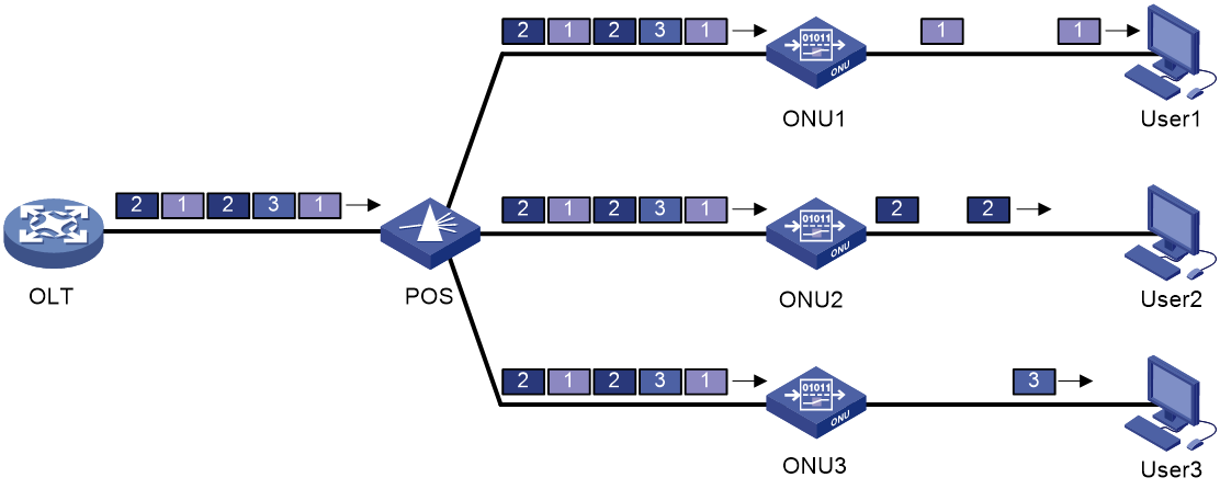
· Downlink data transmission: As shown in Figure 5, the OLT broadcasts the downlink data to all ONUs after data encryption. Each ONU receives its own data based on the LLID of the downlink data and discards the data of other users. Each LLID has an independent cryptographic key and each ONU can only decipher its own data.
Figure 5 Downstream data transmission in EPON system
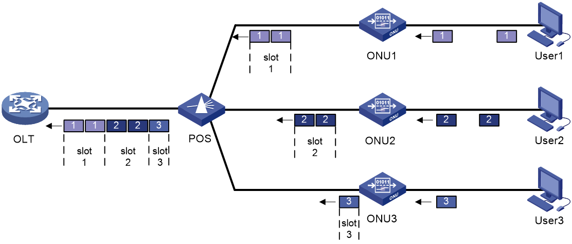
· Upstream data transmission: Each ONU stores the data frames received from the customer site, waiting for the transmit time slot that the OLT allocates for itself. Once the allocated time slot arrives, it transmits all the stored data frames at full line rate. As shown in Figure 6, slots 1, 2, and 3 respectively represent the time slots allocated by the OLT to ONU 1, 2, and 3.
In the upstream direction, data is collected using TDMA (Time Division Multiple Access) technology, ensuring that multiple ONU-to-OLT data signals can be transmitted over a single fiber optic line between OLT and POS without interference between signals.
Figure 6 EPON system upstream data transmission
EPON interface types and numbering
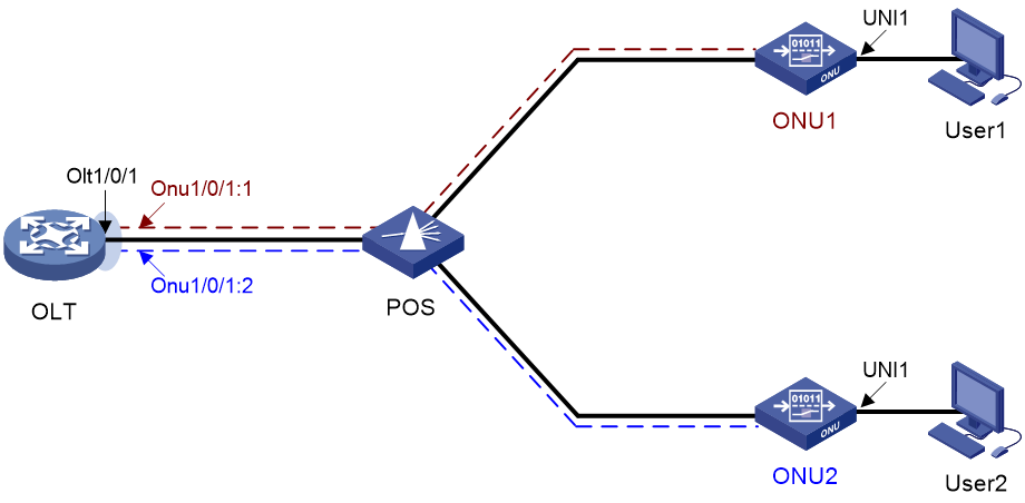
As shown in Figure 7, the EPON system mainly has the following types of interfaces:
· OLT Port: Located on the OLT device, each OLT port can connect to one EPON network.
The OLT port adopts a three-dimensional numbering method: the slot number of the board/ the number of the subcard/ the port number, for example, Olt1/0/1. (Distributed device - Standalone mode) (Distributed device - IRF mode)
The OLT port uses a three-dimensional numbering method: device member number/subcard number/port number, for example, Olt1/0/1. (Centralized IRF device)
· ONU Interface: A logical interface used on the OLT port to establish a connection with the ONU device.
The numbering method for the ONU interface is: OLT port number:ONU interface number, for example, Onu1/0/1:1.
The configuration under the ONU interface is for the ONU devices that connect to the OLT. The ONU interface only has practical significance when the ONU device is bound to a specified ONU interface.
· User Network Interface (UNI): It is the port on the ONU device used for user connection.
Figure 7 Interface numbering in EPON System
OLT redundant backup
In order to meet the high availability (HA) business forwarding requirements, EPON supports redundancy backup for optical links on the OLT side. You can choose one configuration from the following functions:
· EPON redundancy interface: Supports redundancy backup of two OLT ports on the same device or the same IRF.
· OLT fiber optic backup group: Supports cross-device fiber optic backup, that is, when a fault occurs in one of the two OLT devices, traffic can quickly switchover to the standby OLT port of the other device, ensuring the normal run of the insured traffic.
To ensure normal operation after the primary-secondary switchover, the configuration of two OLT ports and all ONUs under them in the fiber optic backup group needs to be identical. However, the EPON redundancy interface avoids this duplicate configuration. After adding two OLT ports to the virtual OLT redundancy interface, you only need to configure this OLT redundancy interface and the ONU redundancy interfaces under it.
EPON redundant interface
Redundant interface numbering rules
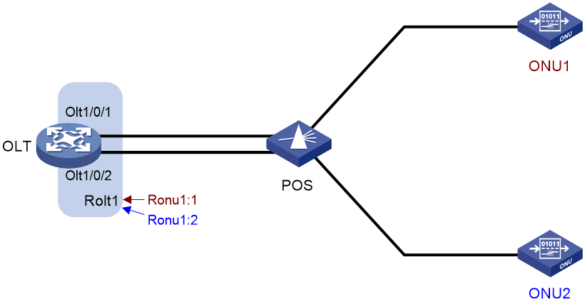
As shown in Figure 8, there are two types of redundancy interfaces in EPON:
· Redundant OLT (ROLT) refers to the Layer 2 logical interface on the OLT device, which is created by bundling two OLT ports together. An ROLT interface number has only one tier, for example, ROLT 1.
· RONU: Redundant ONU interface, which is a Layer 2 logical interface created on an ROLT interface to connect an ONU. The numbering method for the redundancy interface of ONU is "OLT redundancy interface number: ONU redundancy interface number", for example, Ronu1:1.
Once the ONU device is bound to the ONU redundancy interface, it actually communicates data with the activated member port inside the OLT redundancy interface to which it belongs. Therefore, there must be a member port within the OLT redundancy interface, so that the ONU device bound to its ONU redundancy interface can register to that OLT.
Figure 8 EPON Redundancy Interface Diagram
Member port state
Member ports in an ROLT interface can be in one of the following states:
· Active state: Able to send and receive messages. A member port in this state is called an active port.
· Inactive: A port in this state cannot send or receive packets.
Determining the member port state
At any time, only one member port in an ROLT interface can be in active state.
· When the physical states of two member ports are both up, the member port with a higher privilege level is in an active state, while the member port with a lower privilege level is in an inactive state. The privilege level can be configured through the command line.
· When the active port goes down physically, the inactive port will be automatically activated and take over to implement backup between ports.
OLT fiber backup group
A fiber optic backup group includes two OLT ports, under normal circumstances, only the main port is in the forwarding state. When the system experiences an anomaly (such as an open circuit in the main fiber optic or the main OLT port breaks down), the two OLT ports within the backup group will automatically perform an active/standby switchover.
The fiber optic backup groups are divided into ordinary fiber optic backup groups and cross-device fiber optic backup groups.
· The general fiber optic backup group only supports the active/standby switchover of OLT ports on local OLT devices.
· The fiber optic backup group across devices supports active/standby switchover of OLT ports between two devices, providing device-level redundancy protection.
Common fiber backup group
As shown in Figure 9, the two OLT ports that serve as mutual backups belong to the same OLT device.
In a common fiber backup group, you can manually perform primary/secondary switchover between the two member ports.
Figure 9 Common fiber backup group

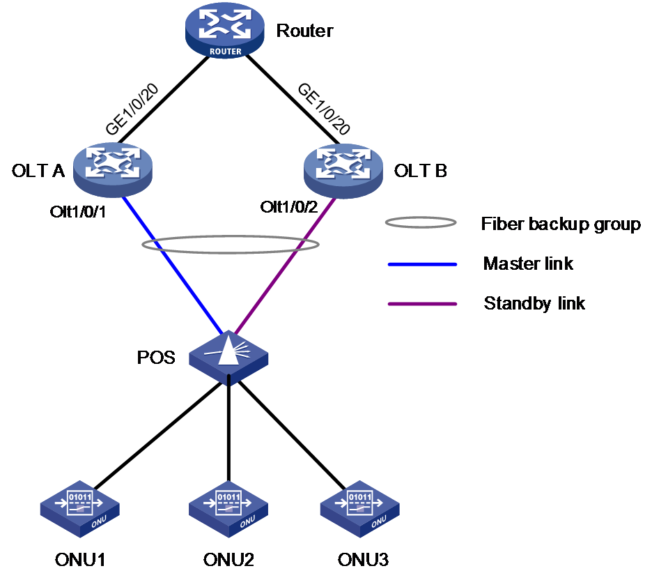
Multidevice fiber backup group
As shown in Figure 10, the fiber optic backup group spanning across devices segregates two OLT ports that mutually backup each other and, subsequently, deploys them onto two different OLT devices. One of the OLT ports on a device is designated as the primary port (corresponding to the Master link in the figure), while the port on the other device is designated as the secondary port (corresponding to the Standby link in the figure).
Two OLT devices synchronize data (including primary/backup port information, ONU online state information, etc.) through a TCP connection. When the primary port is down, the backup port on another OLT device within the backup group will switchover to become the primary port.
Figure 10 Multidevice fiber backup group
Managing ONU devices through OLT
This section introduces the basic technical aspects of remote management of ONU via OLT.
ONU registration and onboarding
Only when the ONU is bound to the ONU interface/redundancy interface of OLT can the ONU pass the legality verification, thereby completing the registration online. The corresponding ONU interface/redundancy interface on the OLT will then become 'up' (referred to as the ONU being "online").
ONU can be bound to the ONU interface or ONU redundancy interface through the following ways:
· Manual binding of ONU to ONU interface/ONU redundancy interface is suitable for use when the number of ONU is small.
· Batch bind ONU: Enable the device to automatically bind unregistered ONU devices to the ONU interface/ONU redundancy interface, but no binding will occur for newly added ONU devices afterwards.
The bulk binding method is suitable when it's confirmed that all ONUs are legit in the initial setup of the network environment, saving a lot of tedious binding operations.
· Automatic ONU binding: This feature allows the device to automatically bind the currently unregistered ONU devices to the ONU/redundancy interface, and also to automatically bind any new ONU devices that are added later.
The automatic binding method is suitable for situations where there is complete trust in the ONU devices connected to the OLT.
When batch binding ONU or auto-binding ONU, if there are OLT redundancy interfaces on the device, priority is given to using ONU redundancy interfaces to bind ONU devices. When the number of ONU interfaces/ONU redundancy interfaces is insufficient, the device will automatically create these logical interfaces to bind ONU devices.
Upgrading ONU
In the EPON system, there are various types of ONU devices in numerous amounts. As different types of ONU require different upgrade files, the task of upgrading ONU devices is quite significant. In order to enhance the efficiency of ONU upgrading and reduce the utilization of the system resources by each command line issued to ONU, besides supporting the function of upgrading single ONU devices, the system also offers the functionality of mass upgrading ONU based on type and OLT port. Currently, the system supports three types of upgrade methods as follows:
· Upgrade all ONU by type: Upgrade all ONUs of the specified type under the switch (the upgrade file can be configured multiple times by type, enabling simultaneous upgrading of different types of ONUs).
After configuring the upgrade for a specified class of ONU under the switch, if the newly created ONU interface or redundancy ONU interface conforms to the specified class and goes online, the switch will automatically upgrade it.
· Upgrade a single ONU: Issue an ONU upgrade command to an individual ONU.
· Upgrade all ONUs under the OLT port: Issue the ONU upgrade command for all created ONUs under the specified OLT port.
Considering the high efficiency and simplicity of maintaining the same type of ONU version across the whole network, it is recommended that users prioritize selecting "Upgrade all ONU by type".
Long light detection of ONU
The OLT supports the detection of ONU Long-Light phenomena (referring to the ONU emitting light not within its allocated time slot, occupying the upstream communication time slots of other ONUs, also known as "Rogue ONU"). It can generate alarms and shut down the light-emitting power of the ONU's PON port.
EPON multicast service
The multicast technology of EPON is primarily used for scenarios such as network television and real-time audio conferences. Its advantages are as follows:
· Data release through point-to-multipoint reduces bandwidth consumption and eases the load on the information source servers and network equipment.
· The user access control supports multicast services.
The OLT supports two types of remote configuration for ONU multicast function: IGMP Snooping (Internet Group Management Protocol Snooping) mode and controlled multicast mode.
IGMP snooping mode
In IGMP Snooping mode, the OLT can allocate the UNI port on the ONU to a specified multicast VLAN. This allows users under the UNI port to only use the multicast IP address corresponding to that multicast VLAN, enabling basic user multicast control permissions.
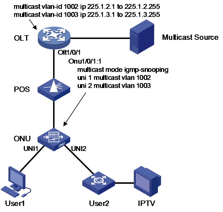
Taking the IPTV networking shown in Figure 11 as an example, by configuring the following functions on the OLT, it is possible to achieve authorization for User1 to stream channels between 225.1.2.1 and 225.1.2.255, and for User2 to stream channels between 225.1.3.1 and 225.1.3.255.
· Configure multicast VLANs 1002 and 1003, and establish mappings between them and the multicast IP addresses.
When the OLT receives an IGMP Join message from the ONU, if the multicast IP address included in the message is not in the mappings, the OLT will directly discard the message.
· The IGMP Snooping function is configured globally and within VLAN 1002 and 1003 in the OLT.
· The OLT configures the ONU device's multicast mode to IGMP Snooping remotely through the ONU interface and adds its UNI 1 and UNI 2 ports to the multicast VLAN 1002 and 1003, respectively.
The multicast service streams distributed to ONU by an OLT all carry a multicast VLAN Tag. UNI ports belonging to a specific multicast VLAN can choose to delete this VLAN Tag or apply a VLAN ID translation upon receiving its matching multicast service stream. For example, if User2 uses a separate home gateway to connect to the UNI port of an ONU to start an IPTV service, and the home gateway needs the multicast stream to have a multicast VLAN Tag, the ONU should translate the VLAN ID of the downstream multicast stream to this user's IPTV VLAN.
Figure 11 Network Diagram for IGMP Snooping Mode
In IGMP Snooping mode, the OLT and ONU primarily achieve dynamic addition/exit of multicast group members through IGMP Join/Leave and Query messages. The suppression function of IGMP membership report message (IGMP Join/Leave message) can reduce the number of these protocol messages, thus reducing bandwidth consumption. The principle is as follows:
1. When the ONU receives a membership report message (IGMP Join/Leave message) from a member of a multicast group, it forwards the message to the OLT.
2. When there are multiple members belonging to a multicast group on the ONU, the OLT will receive the same IGMP membership report messages transmitted by these members.
3. After enabling the IGMP {membership report message} suppression {function}, within a {query} interval, the ONU will only forward the first IGMP {membership report message} from a specific {multicast group} to the OLT, instead of forwarding additional IGMP {membership report messages} from the same {multicast group}. This can help reduce the number of messages in the {network}.
Controllable multicast mode
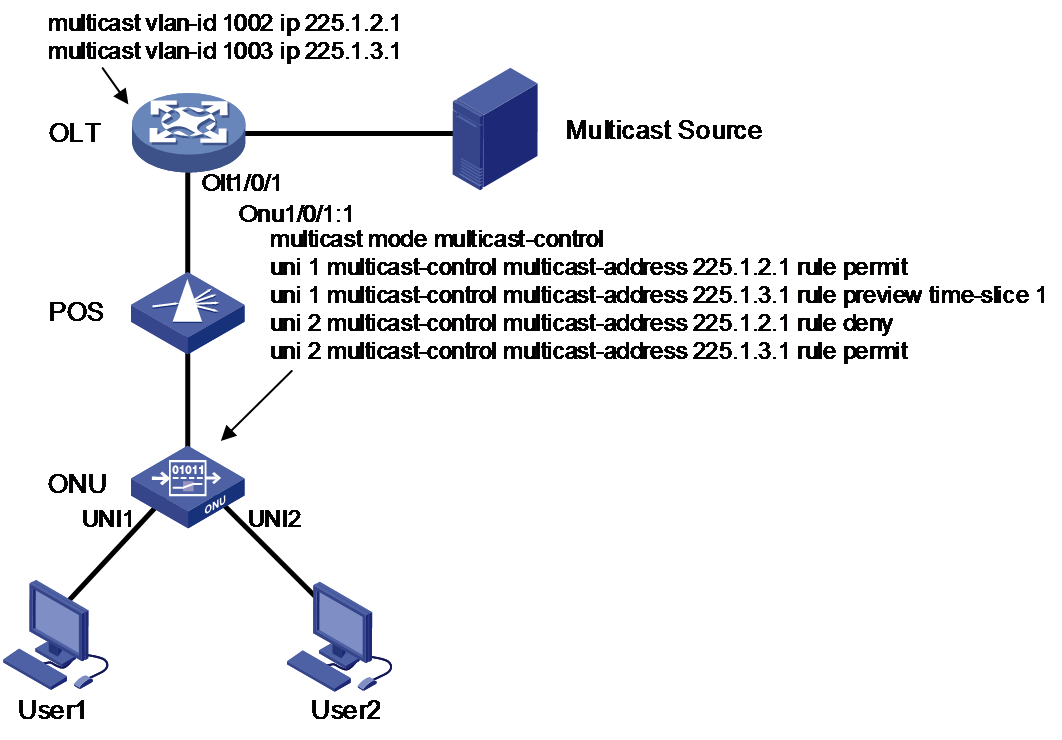
The controllable multicast mode is used for fine control of user multicast permissions. Taking the IPTV networking shown in Figure 12 as an example, by configuring the following functions on the OLT, different access permissions to channels 2 and 3 (corresponding to multicast IP addresses 225.1.2.1 and 225.1.3.1, respectively) can be granted to User1 and User2.
· Configure the multicast VLAN 1002 and 1003 with the mappings between the multicast IP address, then enable the IGMP Snooping function globally and within VLAN 1002 and 1003.
· The OLT remotely configures the multicast mode of the ONU equipment through the ONU interface to be controllable multicast, and configures the business access permissions of the two multicast channels for the UNI 1 and UNI 2 ports as follows:
¡ UNI 1 users are allowed to view channel 2 and have only 1 minute of preview time for channel 3.
¡ UNI 2 users are not allowed to view channel 2 but are allowed to view channel 3.
Figure 12 Controllable multicast mode network diagram
In the controllable multicast mode, the OLT and ONU are responsible for the following functions:
· OLT centrally manages users' multicast business access permissions.
¡ The OLT uses the user's LLID and the VLAN Tag carried by the upstream IGMP Join message (consistent with the UNI port number) for user identification and determines whether the user has access permission for the requested multicast business and its parameters based on the multicast permission control table.
¡ The
OLT distributes the user's access permissions for the multicast channel to the
ONU through extended multicast control OAM messages. The ONU then performs
forwarding or discarding operations for the user's multicast business flow.
Multicast permission control is centrally managed by the OLT, with the OLT
being the main agent for multicast permission management and the ONU being the
executor of multicast permission management.
· The ONU only handles the current multicast business flow control within the ONU.
The ONU adds a VLAN Tag identifying the user's identity (consistent with the UNI port number) to the received IGMP Join/Leave messages without VLAN Tag and forwards them to the OLT. It then adds or deletes local group address filtering and multicast forwarding entries based on the multicast control OAM messages issued by the OLT (which contains a series of multicast control table entries), and finally performs the corresponding forwarding or discarding operations for the multicast business flow.
EPON PoE
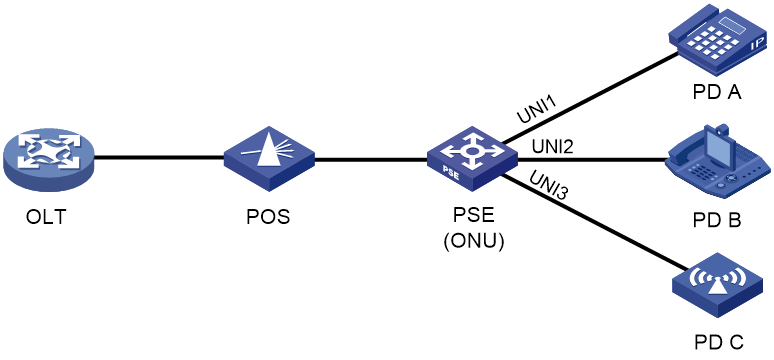
The OLT can remotely configure the PoE (Power over Ethernet) function of the ONU device, which specifically includes enabling/disabling the PoE function of the UNI port, setting the power supply privilege level, and the maximum power supply.
The PoE model of the EPON system is shown in Figure 13, which includes:
· The Power Sourcing Equipment (PSE) is an ONU device that provides power to the PD through the UNI port.
· PD (Powered Device): A device that receives power from the PSE (Power Sourcing Equipment), such as an IP phone, wireless Access Point (AP), etc.
EPON applications
Residential area video surveillance
As shown in Figure 14, cameras can be deployed in residential areas using the ONU access method, and the OLT can centrally manage the ONUs.
The point-to-multipoint optical network structure of EPON can cover a wide range of monitoring points, while providing high bandwidth, transparently transmitting video frequency (VF) data to the monitoring center within the IP network.

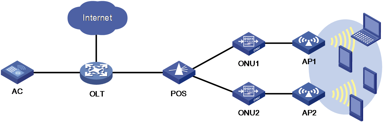
Campus wireless network
As shown in Figure 15, multiple APs (Access Point) are deployed in the campus to provide wireless internet services. The AC (Access Controller) can manage APs via the EPON optical network.
This type of network has the following advantages:
· Unified traffic load and centralized AP management, resulting in reduced operational costs.
· Using passive optical devices instead of active equipment can greatly reduce the failure rate.
· Point-to-multipoint network structure supports flexible expansion.
EPON technology parameters
The OLT device supports the following two types of EPON boards:
· 1G-EPON board: only supports connecting to 1G ONUs.
· 10G-EPON board: besides connecting to 1G ONUs, it also supports connecting to the following two types of ONUs:
¡ 10G/1G ONU: known as "asymmetric ONU".
¡ 10G/10G ONU: known as "symmetric ONU", requiring the installation of symmetric optical modules on the corresponding OLT port.
The bandwidth and wavelength of EPON are related to the type of ONU connected to the EPON board, as shown in Table 2. Here, 1G-EPON refers to the scenario where a 1G-EPON board or 10G-EPON board connects to a 1G ONU.
Table 2 EPON bandwidth and wavelength
|
Direction of rate/wavelength |
1G-EPON |
10G-EPON |
|
Uplink Bandwidth |
1Gbit/s |
· Asymmetric ONU: 1Gbit/s · Symmetric ONU: 10Gbit/s |
|
Downlink Bandwidth |
1Gbit/s |
10Gbit/s |
|
Upstream wavelength |
1310nm |
· Asymmetric ONU: 1310nm · Symmetric ONU: 1270nm |
|
Downstream wavelength |
1490nm |
1577nm |
