- Released At: 14-01-2025
- Page Views:
- Downloads:
- Table of Contents
- Related Documents
-
H3C Electronic Shelf Label Solution Deployment Guide
Copyright © 2025 New H3C Technologies Co., Ltd. All rights reserved.
No part of this manual may be reproduced or transmitted in any form or by any means without prior written consent of Hangzhou H3C Technologies Co., Ltd.
Except for the trademarks of New H3C Technologies Co., Ltd., any trademarks that may be mentioned in this document are the property of their respective owners.
This document provides generic technical information, some of which might not be applicable to your products.
Contents
Software and hardware compatibility
Configuration example (AC+fit AP networking)
Configuring network interconnection between the AC, switches, and the AP
Configuring WLAN service settings
Configuring network interconnection between ESL controllers and the ESL management system
Configuration example (cloud networking)
Configuring network interconnection between the Cloudnet platform, the switch, and the AP
Registering and onboarding the AP on the Cloudnet platform
Configuring WLAN service settings
Configuring network interconnection between ESL controllers and the ESL management system
Introduction
Background
In modern supermarket retail scenarios, many businesses still rely on paper shelf labels to display product prices. However, this traditional method has several significant drawbacks, making it increasingly unsuitable for efficient and precise management needs:
· High labor maintenance costs: Paper shelf labels require regular replacement and adjustment, a process that is both time-consuming and labor-intensive, increasing operation expenditure (OPEX).
· Inefficient maintenance: Employees need to replace shelf labels for each product individually, resulting in low efficiency and high consumption of human resources.
· Prone to error and customer experience issues: Manual operations are prone to error, and inaccurate price displays can lead to customer complaints, impacting the shopping experience and potentially damaging the business's reputation.
To address these issues, H3C has introduced an advanced smart retail IoT solution—the electronic shelf label (ESL) solution, which replaces traditional paper shelf labels with electronic ones. By adopting ESLs, stores can significantly enhance operational efficiency and accuracy, optimize the customer shopping experience, and establish a more modern brand image.
Solution benefits
Adopting an electronic shelf label solution offers merchants numerous significant advantages:
· Cost savings and profit enhancement: By reducing the frequency of manual maintenance and paper replacement, it significantly lowers operation expenditure (OPEX), thereby increasing the profit margin for merchants.
· Automated management for increased efficiency: ESLs enable automated management, greatly enhancing the efficiency of label updates and management, allowing staff to focus more on other important aspects of store operation.
· Reduced errors and enhanced customer satisfaction: The automated system decreases the likelihood of human errors, reducing customer complaints and enhancing customer satisfaction rate (CSR) and trust level.
· Flexible and efficient price adjustments: Labels feature a rapid and accurate price change function, aiding stores in easily adjusting prices during promotions. The ESL platform supports integration with customer pricing systems, further enhancing the accuracy and efficiency of price updates. A single click can synchronize the price display of all products, avoiding discrepancies that could lead to disputes.
· Diverse display options: Provides clear, customizable label display templates, offering more valuable product information to customers besides price information.
· Simplified network infrastructure: ESLs utilize existing WLAN networks for multiplexing, achieving network integration. This consolidation not only reduces the cost of network deployment and maintenance but also facilitates unified management by administrators.
By using the ESL technology, merchants can achieve efficient internal operations and significantly improve the customer shopping experience, establishing a more competitive and forward-thinking brand image.
Network architecture
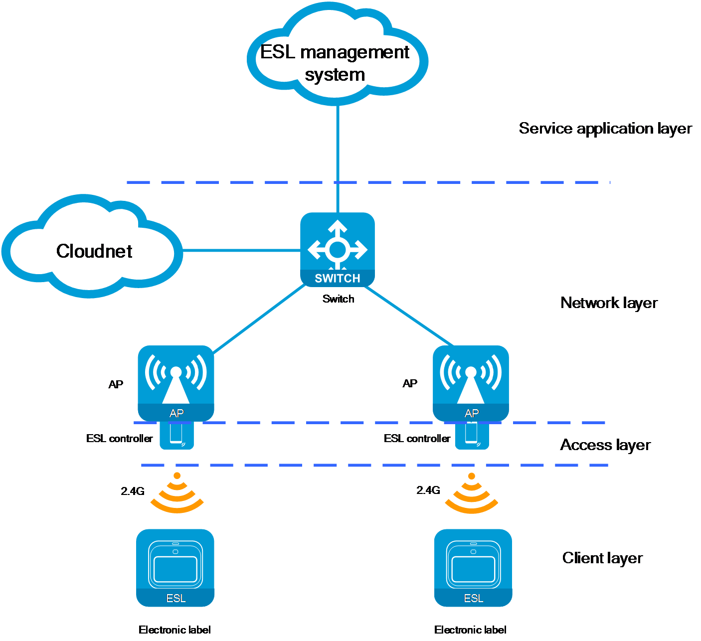
As shown in Figure 1 and Figure 2, the networking architecture of the ESL solution can be divided into the following key layers: client layer, access layer, network layer, and service application layer. Each layer performs a unique function, and all the layers collectively support the efficient operation of the ESL system.
|
|
NOTE: H3C only provides the equipment for the network layer. The devices for the other layers are supplied by third-party partner vendors. |
Figure 1 ESL network architecture (AC+fit AP)
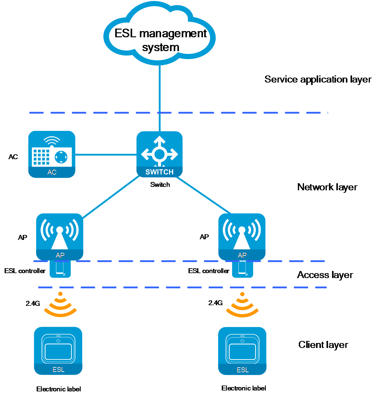
Figure 2 ESL network architecture (cloud)
· Client layer
¡ Components: ESLs installed on the shelves.
¡ Functionality: The screens of these labels are used to display key product information, such as price, name, and promotional details. The ESLs contain RF modules that automatically receive information from the ESL controller through wireless signals and update the display content, ensuring real-time accuracy of the displayed information.
|
|
NOTE: Currently, the communication between ESLs and ESL controllers uses the proprietary communication protocol High-density Low Power Cellular Network (HiLPC) of Hanshow, operating on the 2.4GHz band. This is a new wireless communication protocol released by Hanshow Technology, designed to enhance the communication speed and efficiency of ESLs. The HiLPC protocol is widely used in industries such as retail, industrial manufacturing, and logistics. Through this protocol, ESLs can update promotional information in real-time, adjust pricing dynamically, and synchronize pricing both online and offline, further promoting digital transformation and innovation in these industries. |
· Access layer
¡ Components: ESL controllers.
¡ Functionality: As a crucial component of the ESL solution, the ESL controller facilitates data interaction between the ESL management system and the ESLs.
· Network layer
¡ Components: Network devices such as APs, ACs, switches, and the Cloudnet platform. The composition might vary depending on the network architecture.
¡ Functionality: The responsibility of the network layer is to forward data packets for ESLs, ensuring smooth data communication between the ESL controllers and the ESL management system. The network layer devices do not parse or process the ESL packets. They only ensure the stability of information transmission and the reliability of connections. The AP devices in the network layer provide interfaces (such as USB interfaces) for the ESL controller to connect.
· Service application layer
¡ Components: ESL management system.
¡ Functionality: The ESL management system is responsible for issuing information update tasks to the ESL controller and provides management functions for both the ESL controller and the ESLs.
Through effective collaboration across all layers, the ESL solution not only enhances operational efficiency in the retail industry but also modernizes information management. Accurate and timely transmission of product information offers customers a better shopping experience, while simplifying the maintenance processes for merchants.
Using this document
This document focuses on the configuration details related to network layer equipment. For the configuration of ESLs, ESL controllers, and the ESL management system, contact the respective product manufacturers. This document will not describe specific configuration steps.
Software and hardware compatibility
|
|
NOTE: The product models supported by the ESL solution might change with updates to software and hardware versions. |
The following table shows the requirements of the ESL solution on produce models and software versions:
Table 1 ESL hardware and software compatibility
|
Hardware series |
Model |
Compatible software versions |
|
WA5300 series |
WA538-WW WA538-JP |
R2462 and later |
|
WA6500A series |
WA6526 WA6126 WA6526E WA6120H WA6520H WA6126-JP WA6520H-JP |
R2601 and later |
Restrictions and guidelines
· The USB interface on an AP is disabled by default. Before connecting the ESL controller to an AP, make sure the USB interface is enabled on the AP.
¡ The enabled USB interface can take effect only when the AP input power level is middle or high.
¡ When the input power level is middle, the maximum capacity of the MIMO mode degrades to 2x2 after you enable the USB interface. After you disable the USB interface, the maximum capacity restores to 4x4.
· After you connect the ESL controller to an AP, the system automatically generates a Layer 2 Ethernet interface. You can configure the interface to achieve network interconnection between the ESL controller and the ESL management system.
· After the AP restarts, you must reconfigure the dynamic Layer 2 Ethernet interface corresponding to the ESL controller.
· The ESL controller operates on the 2.4 GHz band. As a best practice to avoid affecting the update speed of ESLs, disable 2.4 GHz radios on APs.
· In service planning, specify a separate VLAN for ESLs which is different from the VLAN for WLAN services to help better management and maintenance.
Configuration example (AC+fit AP networking)
Network configuration
A supermarket plans to deploy a network system that can provide a wireless Internet environment and support IoT applications. To efficiently display and manage pricing for in-store products, the network system also needs to integrate ESL functionality.
· The out-of-path Layer 2 networking method is used to achieve high-efficiency connection and management of network devices.
· Configure the switch to act as the DHCP server to assign IP addresses to the AP, clients, and the ESL controller.
· Use the local forwarding method for the AP to forward data traffic of clients.

Analysis
The configuration process is as follows:
1. Configure network settings for the AC, the switch, and the AP to reach each other.
2. Configure the AP to come online.
3. Configure WLAN service settings.
4. Configure the ESL controller and the ESL management system to reach each other and configure ESL-related services.
Network planning
Table 2 Network planning example
|
Configuration item |
Planning data |
|
AP management VLAN |
VLAN 100 |
|
Wireless service VLAN |
VLAN 200 |
|
VLAN for ESL controller and ESL management system interconnection |
VLAN 300 |
|
DHCP server |
Switch acts as the DHCP server to assign IP addresses to clients, the AP, and ESL controllers |
|
IP address pool for AP |
192.168.1.3 to 192.168.1.254/24 |
|
IP address pool for clients |
192.168.2.2 to 192.168.2.254/24 |
|
IP address pool for ESL controllers |
192.168.3.3 to 192.168.3.254/24 |
|
IP address of the AC |
Vlan-interface 100: 192.168.1.2/24 |
|
IP address of the switch |
Vlan-interface 100: 192.168.1.1/24 Vlan-interface 200: 192.168.2.1/24 Vlan-interface 300: 192.168.3.1/24 |
|
IP address of the ESL management system |
192.168.3.2/24 |
Procedures
|
|
NOTE: This configuration example describes only the steps related to the network interconnection between ESL controller and ESL management system. |
Configuring network interconnection between the AC, switches, and the AP
Details not shown. For more information, see H3C Access Controllers Configuration Examples.
Configuring AP settings
Details not shown. For more information, see H3C Access Controllers Configuration Examples.
Configuring WLAN service settings
Details not shown. For more information, see H3C Access Controllers Configuration Examples.
Configuring network interconnection between ESL controllers and the ESL management system
1. Configure the switch interfaces:
# Create VLAN 300 and VLAN-interface 300, and assign an IP address to the interface. VLAN 300 will be used for network interconnection between ESL controllers and the ESL management system.
<Switch> system-view
[Switch] vlan 300
[Switch-vlan300] quit
[Switch] interface vlan-interface 300
[Switch-Vlan-interface300] ip address 192.168.3.1 24
[Switch-Vlan-interface300] quit
# Specify GigabitEthernet 1/0/2 that connects the switch to the AP as a trunk port, assign the port to all VLANs, and set the PVID to 100.
[Switch] interface GigabitEthernet 1/0/2
[Switch-GigabitEthernet1/0/2] port link-type trunk
[Switch-GigabitEthernet1/0/2] port trunk permit vlan all
[Switch-GigabitEthernet1/0/2] port trunk pvid vlan 100
# Enable PoE on GigabitEthernet 1/0/2.
[Switch-GigabitEthernet1/0/2] poe enable
[Switch-GigabitEthernet1/0/2] quit
# Specify GigabitEthernet 1/0/3 that connects the switch to the ESL management system as an access port, and assign the port to VLAN 300.
[Switch] interface gigabitethernet 1/0/3
[Switch-GigabitEthernet1/0/3] port link-type access
[Switch-GigabitEthernet1/0/3] port access vlan 300
[Switch-GigabitEthernet1/0/3] quit
2. Configure the DHCP service:
# Enable the DHCP feature.
[Switch] dhcp enable
# Create a DHCP address pool named vlan300 for assigning IP addresses to ESL controllers, and specify subnet 192.168.3.0/24 for dynamic address allocation. Specify the gateway address as 192.168.3.1, and specify the DNS address. In this example, the DNS address is the same as the gateway address.
[Switch] dhcp server ip-pool vlan300
[Switch-dhcp-pool-vlan300] network 192.168.3.0 mask 255.255.255.0
[Switch-dhcp-pool-vlan300] gateway-list 192.168.3.1
[Switch-dhcp-pool-vlan300] dns-list 192.168.3.1
[Switch-dhcp-pool-vlan300] forbidden-ip 192.168.3.1 192.168.3.2
[Switch-dhcp-pool-vlan300] quit
3. Configure the USB interface on the AP and specify the default input power level:
|
|
NOTE: As a best practice, configure wireless settings based on AP groups for large-scale networks. |
# Enable the USB interface on the AP and set the default input power level to high.
<AC> system-view
[AC] wlan ap-group group1
[AC-wlan-ap-group-group1] ap-model WA6526
[AC-wlan-ap-group-group1-ap-model-WA6526] usb enable
[AC-wlan-ap-group-group1-ap-model-WA6526] power-level default high
[AC-wlan-ap-group-group1-ap-model-WA6526] quit
[AC-wlan-ap-group-group1] quit
4. View the number of the Layer 2 Ethernet interface generated dynamically:
a. Before connecting an ESL controller to an AP, use the display wlan ap { all | name ap-name } interface command on the AC to view the Ethernet interface information for online APs.
b. After connecting an ESL controller to an AP, execute the display wlan ap { all | name ap-name } interface command again to view the Layer 2 Ethernet interface generated dynamically.
5. Use a map file to issue the configuration:
|
|
NOTE: · Edit the apcfg.txt configuration file in the command configuration order and upload the file to the AC. After the AP comes online from the AC, execute the map-configuration command to issue the configuration to the AP. · Configure the interface that connects the AP to the ESL controller as an access port, assign the port to VLAN 300, and disable port isolation. This section uses SGE1/0/2 as an example. |
# The content of the apcfg.txt configuration file is as follows:
system-view
vlan 200
quit
vlan 300
quit
interface GigabitEthernet 1/0/1
undo port-isolate enable
port link-type trunk
port trunk permit vlan all
quit
interface Smartrate-Ethernet 1/0/2
undo port-isolate enable
port access vlan 300
quit
# Specify the AP configuration file as apcfg.txt in the AP group's AP model view.
[AC] wlan ap-group group1
[AC-wlan-ap-group-group1] ap-model WA6526
[AC-wlan-ap-group-group1-ap-model-WA6526] map-configuration apcfg.txt
6. View the IP address of the ESL controller obtained from the DHCP server.
On the switch (DHCP server), you can use the display dhcp server ip-in-use command to view the IP address assigned to the ESL controller. Users can log in to the local Web interface of the ESL controller using this IP address to perform viewing and management operations. For more information, contact the product manufacturer to obtain detailed guidance documentation.
Configuring ESL functions
Register ESLs, associate ESL IDs with product codes, and configure ESL services.
For more information, contact the product manufacturer to obtain detailed guidance documentation.
Configuration example (cloud networking)
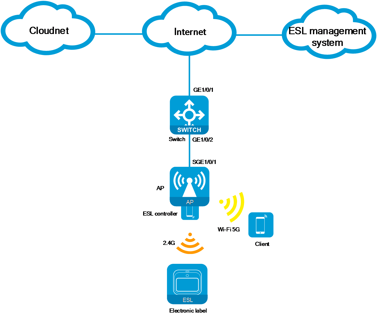
Network configuration
A supermarket plans to deploy a network system that can provide a wireless Internet environment and support IoT applications. To efficiently display and manage pricing for in-store products, the network system also needs to integrate ESL functionality.
· The AP operates in cloud mode and registers on the Cloudnet platform through the switch. You can manage the AP through the Cloudnet platform.
· Configure the switch to act as the DHCP server to assign IP addresses to the AP, clients, and ESL controllers.
Figure 4 Network diagram
Analysis
The configuration process is as follows:
1. Configure network interconnection between the Cloudnet platform, the switch, and the AP.
2. Configure WLAN service settings.
3. Configure the ESL controller and the ESL management system to reach each other and configure ESL-related services.
Network planning
Table 3 Network planning example
|
Configuration item |
Planning data |
|
AP management VLAN |
VLAN 100 |
|
Wireless service VLAN |
VLAN 200 |
|
VLAN for ESL controller and ESL management system interconnection |
VLAN 300 |
|
DHCP server |
Switch acts as the DHCP server to assign IP addresses to clients, the AP, and ESL controllers |
|
IP address pool for AP |
192.168.1.2 to 192.168.1.254/24 |
|
IP address pool for clients |
192.168.2.2 to 192.168.2.254/24 |
|
IP address pool for ESL controllers |
192.168.3.2 to 192.168.3.254/24 |
|
IP address of the switch |
Vlan-interface 100: 192.168.1.1/24 Vlan-interface 200: 192.168.2.1/24 Vlan-interface 300: 192.168.3.1/24 |
Procedures
|
|
NOTE: This configuration example describes only the steps related to the network interconnection between ESL controller and ESL management system. |
Configuring network interconnection between the Cloudnet platform, the switch, and the AP
Details not shown. For more information, see H3C Access Point Configuration Examples.
Registering and onboarding the AP on the Cloudnet platform
Details not shown. For more information, see H3C Cloudnet Feature Guide.
Configuring WLAN service settings
Details not shown. For more information, see H3C Access Point Configuration Examples.
Configuring network interconnection between ESL controllers and the ESL management system
1. Configure the switch interfaces:
# Create VLAN 300 and VLAN-interface 300, and assign an IP address to the interface. VLAN 300 will be used for network interconnection between ESL controllers and the ESL management system.
<Switch> system-view
[Switch] vlan 300
[Switch-vlan300] quit
[Switch] interface vlan-interface 300
[Switch-Vlan-interface300] ip address 192.168.3.1 24
[Switch-Vlan-interface300] quit
# Specify GigabitEthernet 1/0/2 that connects the switch to the AP as a trunk port, assign the port to all VLANs, and set the PVID to 100.
[Switch] interface GigabitEthernet 1/0/2
[Switch-GigabitEthernet1/0/2] port link-type trunk
[Switch-GigabitEthernet1/0/2] port trunk permit vlan all
[Switch-GigabitEthernet1/0/2] port trunk pvid vlan 100
# Enable PoE on GigabitEthernet 1/0/2.
[Switch-GigabitEthernet1/0/2] poe enable
[Switch-GigabitEthernet1/0/2] quit
# Configure VLAN-interface 1 as the egress interface to the Internet and configure default routes. (Details not shown.)
2. Configure the DHCP service:
# Enable the DHCP service.
[Switch] dhcp enable
# Create a DHCP address pool named vlan300 for assigning IP addresses to ESL controllers, and specify subnet 192.168.3.0/24 for dynamic address allocation. Specify the gateway address as 192.168.3.1, and specify the DNS address. In this example, the DNS address is the same as the gateway address.
[Switch] dhcp server ip-pool vlan300
[Switch-dhcp-pool-vlan300] network 192.168.3.0 mask 255.255.255.0
[Switch-dhcp-pool-vlan300] gateway-list 192.168.3.1
[Switch-dhcp-pool-vlan300] dns-list 192.168.3.1
[Switch-dhcp-pool-vlan300] forbidden-ip 192.168.3.1
[Switch-dhcp-pool-vlan300] quit
3. Configure the USB interface on the AP and specify the default input power level.
a. Log into the Cloudnet platform, and click Network on the top navigation bar. Select a branch and a site, and navigate to Settings > Cloud APs > CLI.
Figure 5 CLI page
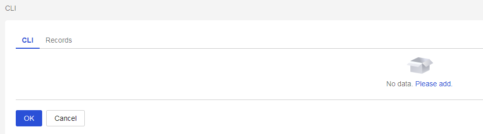
b. Click Add. Select the target AP model, and then click OK.
Figure 6 Selecting the target AP model

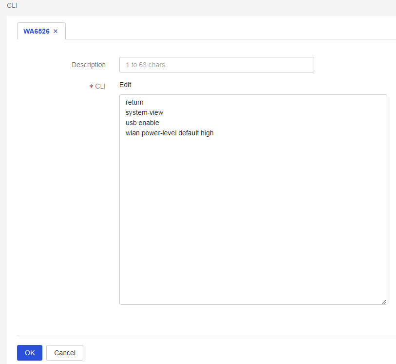
c. Enable the USB interface on the AP and set the default input power level to high. Click OK to issue the configuration.
Figure 7 Command line configuration
d. Click the Records tab and verify if the configuration is issued successfully.
Figure 8 Verifying the result

4. Configure the VLAN for the ESL controller.
a. Navigate to Settings > Cloud APs > VLAN Settings.
Figure 9 VLAN settings
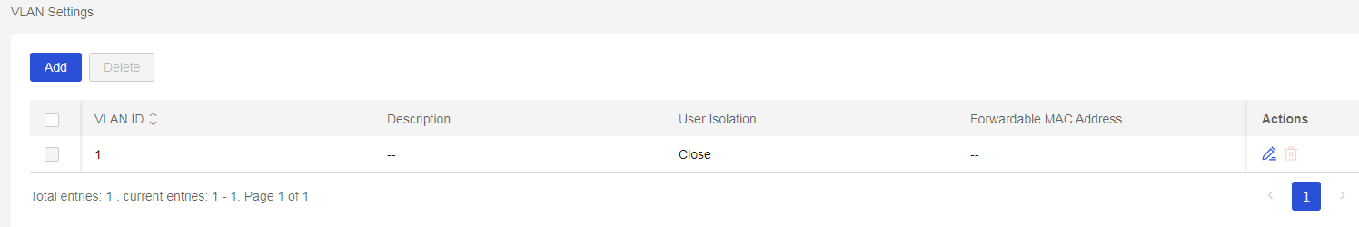
b. Click Add. Create VLAN 300. VLAN 300 will be used for network interconnection between the ESL controller and the ESL management system. Click OK.
Figure 10 Adding a VLAN instance

5. Configure the interface that connects the AP to the ESL controller.
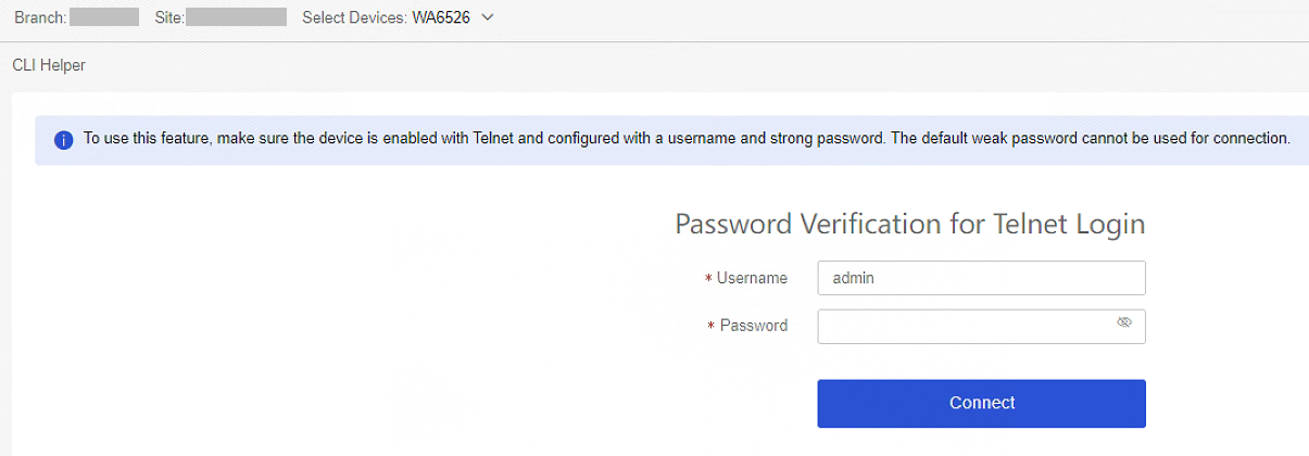
a. Navigate to Maintain > CLI Helper. Select the target site and device at the upper left corner of the workpane. Log into the AP through Telnet and configure the AP downstream Ethernet interface connecting to the ESL controller.
Figure 11 CLI helper
b. View Ethernet interface information on the AP. Before and after connecting the ESL controller to the AP, use the display interface brief command on the AP to view Ethernet interface information. The newly added Ethernet interface is the Layer 2 Ethernet interface dynamically generated.
Figure 12 Viewing the dynamically generated Layer 2 Ethernet interface
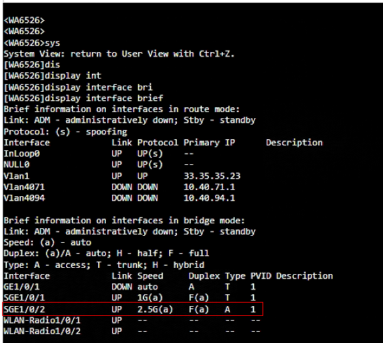
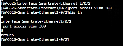
c. Configure the AP interface (SGE1/0/2 in this example) connecting the ESL controller as an access port, and set the PVID to 300.
Figure 13 Configuring the access port
6. View the IP address of the ESL controller obtained from the DHCP server.
On the switch (DHCP server), you can use the display dhcp server ip-in-use command to view the IP address assigned to the ESL controller. Users can log in to the local Web interface of the ESL controller using this IP address to perform viewing and management operations. For more information, contact the product manufacturer to obtain detailed guidance documentation.
Configure ESL functions
Register ESLs, associate ESL IDs with product codes, and configure ESL services.
For more information, contact the product manufacturer to obtain detailed guidance documentation.
Related documentation
· H3C Access Controller Configuration Examples
· H3C Cloudnet Feature Guide
· H3C Access Point Configuration Examples
